

Page 1
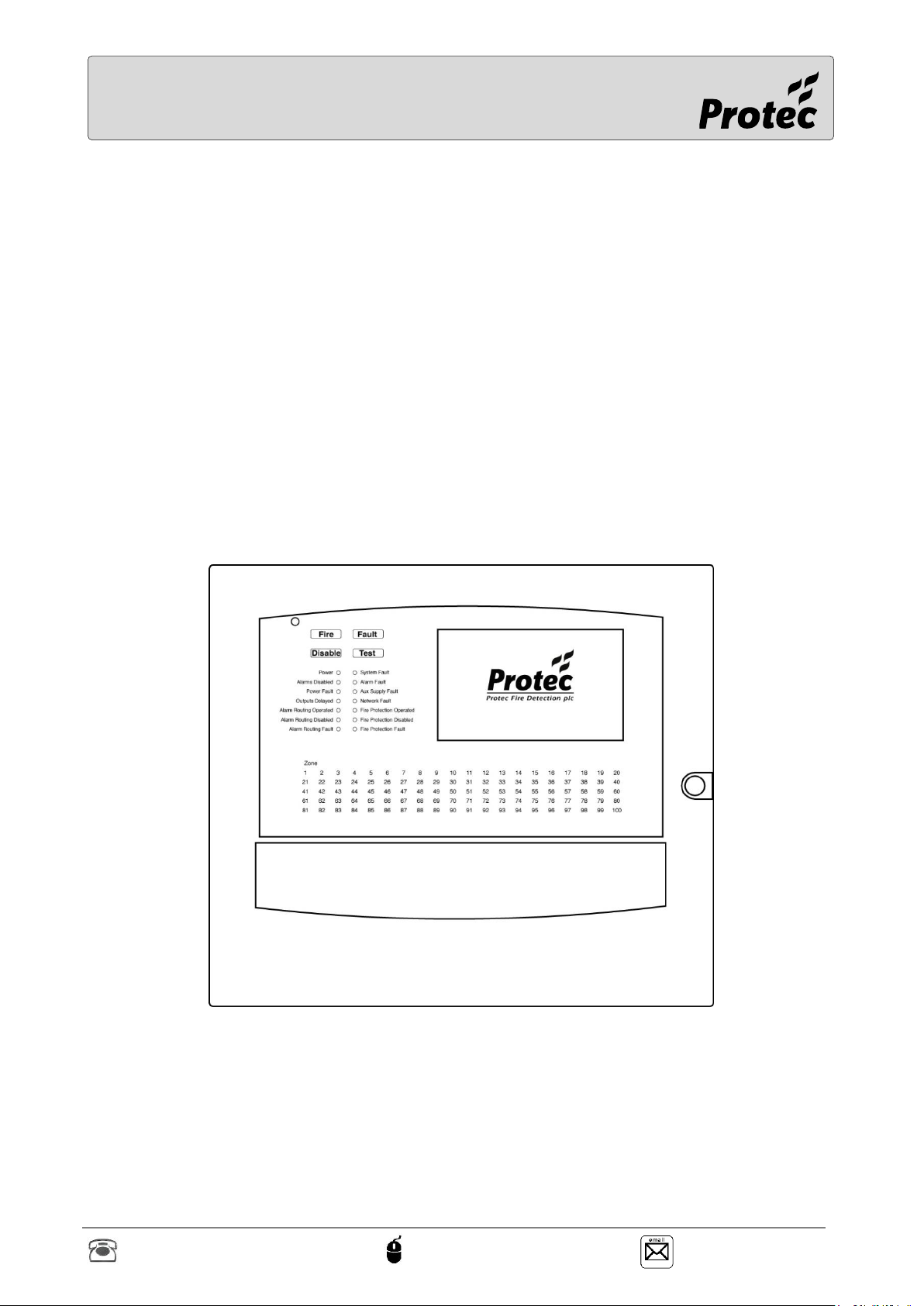
Algo-Tec™ 6500/6600
INTERACTIVE DIGITAL
ADDRESSABLE FIRE CONTROL
SYSTEM (1-4 LOOPS)
COMMISSIONING MANUAL
Protec Fire Detection plc, Protec House, Churchill Way, Nelson, Lancashire, BB9 6RT, ENGLAND
+44 (0) 1282 717171 www.protec.co.uk [email protected]
Page 2

Issue
Modification Detail
Author
Date
2.8
Updated DLP Card addresses
Updated loop Initialisation Fault
Updated device type fault
Added Device Zone Trans Fault
PD
12/12/2018
2.9
Added description of the Promoted master
Updated the description of the MIMIC Device
Missing fault
Added description of Deluge Drive Limit Fault
Updated the description of the Unknown
Active Device Fault
Added damper control module faults
PD
02/05/2019
2.10
Added description of the Loop Disablement
CRC Fault.
Added description of the Loop DLP Queue
fault.
Updated licence fault descriptions.
Added description of the WODU Interface
Board Missing fault.
Updated the description of the Unknown
Active Device Fault.
Renamed Circuit Fault as Supply Out Fault
and updated the description.
Renamed Set Point Position fault as Position
Fault and updated the description.
PD
01/07/2019
3
Minor changes
PD
19/07/2019
Document Revision Details
Notice
This manual may be revised as a result of enhancements to the system software or hardware. Check
for revisions to this manual, and download them, from the website www.protec.co.uk
RDM0002/3 Page 2 of 57 © 2015 - 2019 Protec Fire Detection plc
Page 3

Table of Contents
DOCUMENT REVISION DETAILS ................................................................................................................2
INTRODUCTION .........................................................................................................................................5
IMPORTANT INFORMATION FOR 19” RACK SYSTEMS ..................... ERROR! BOOKMARK NOT DEFINED.
1.0 COMMISSIONING MENUS ...............................................................................................................6
1.1 Login ...................................................................................................................................................... 6
1.2 Entering the Menu System ................................................................................................................. 7
1.3 Tools Menu ........................................................................................................................................... 8
1.4 Loop Tools ............................................................................................................................................. 9
1.5 Loop logging ....................................................................................................................................... 10
1.6 Allocate Addresses ............................................................................................................................. 11
1.7 Printer Menu ....................................................................................................................................... 13
1.8 Print current events ........................................................................................................................... 14
1.9 Print Historic Events .......................................................................................................................... 15
1.10 Diagnostic Tools ............................................................................................................................. 16
1.11 Networking ..................................................................................................................................... 17
1.12 Mapping Info .................................................................................................................................. 18
1.13 Quality .............................................................................................................................................. 22
1.14 Loop Info ......................................................................................................................................... 23
1.15 Clear All Disablements .................................................................................................................. 25
1.16 Rebuild ............................................................................................................................................. 25
1.17 Test menu ........................................................................................................................................ 26
1.18 Test options..................................................................................................................................... 27
1.19 Service Info...................................................................................................................................... 28
1.20 Upgrade ........................................................................................................................................... 29
2.0 FAULT EVENTS ................................................................................................................................ 30
2.1 Panel faults (Non-latching) ............................................................................................................... 30
2.2 Panel faults (Latching) ....................................................................................................................... 32
2.3 Network Faults ................................................................................................................................... 35
2.4 Loop faults .......................................................................................................................................... 37
2.5 Loop Device faults .............................................................................................................................. 39
2.6 6000 Digital Device Fault Information ............................................................................................ 41
2.7 IO faults ............................................................................................................................................... 46
2.8 Alarm events ....................................................................................................................................... 47
2.9 DLP Card Identification ..................................................................................................................... 47
3.0 CARD HARDWARE INDICATIONS .................................................................................................. 48
3.1 System Controller Card ..................................................................................................................... 48
3.2 Network Card ..................................................................................................................................... 49
3.3 I/O Card ............................................................................................................................................... 50
3.4 Loop Card ............................................................................................................................................ 51
3.5 Display Card ........................................................................................................................................ 52
4.0 TOUCH SCREEN CALIBRATION ..................................................................................................... 53
5.0 6500 TECHNICAL SPECIFICATION ................................................................................................. 54
RDM0002/3 Page 3 of 57 © 2015 - 2019 Protec Fire Detection plc
Page 4

6.0 6600 TECHNICAL SPECIFICATION ................................................................................................. 55
7.0 STANDARDS, DIRECTIVES AND REGULATIONS INFORMATION ................................................. 56
RDM0002/3 Page 4 of 57 © 2015 - 2019 Protec Fire Detection plc
Page 5
Introduction
This manual applies to the Protec 6500 and 6600 fire alarm control panels however for convenience;
reference will be made only to the ‘6500’. Everything in this manual applies to the 6500 and 6600
unless stated otherwise.
The Protec 6500 Fire Alarm Control Panel has been designed and manufactured in the United
Kingdom and complies fully with current standards dictating fire alarm system design practice ( EN54
parts 2 and 4 ).
This equipment and its associated connections must be installed, commissioned and
maintained by a suitably trained skilled and competent person.
This equipment is not guaranteed unless installed and commissioned in accordance with
current national standards
There are no user serviceable parts inside the 6500. The equipment and its associated
connections must be installed, commissioned and maintained by a suitably trained,
skilled and competent person. A separate 6500 Installation Manual is available.
It is assumed that the commissioning engineer has read the 6500 User Manual and is
therefore familiar with the basic operation of a 6500 fire panel.
For information on programming the panel and communicating via the PC using the
commissioning software, refer to the Commissioning Software User Manual
RDM0002/3 Page 5 of 57 © 2015 - 2019 Protec Fire Detection plc
Page 6
1.0 Commissioning Menus
1.1 Login
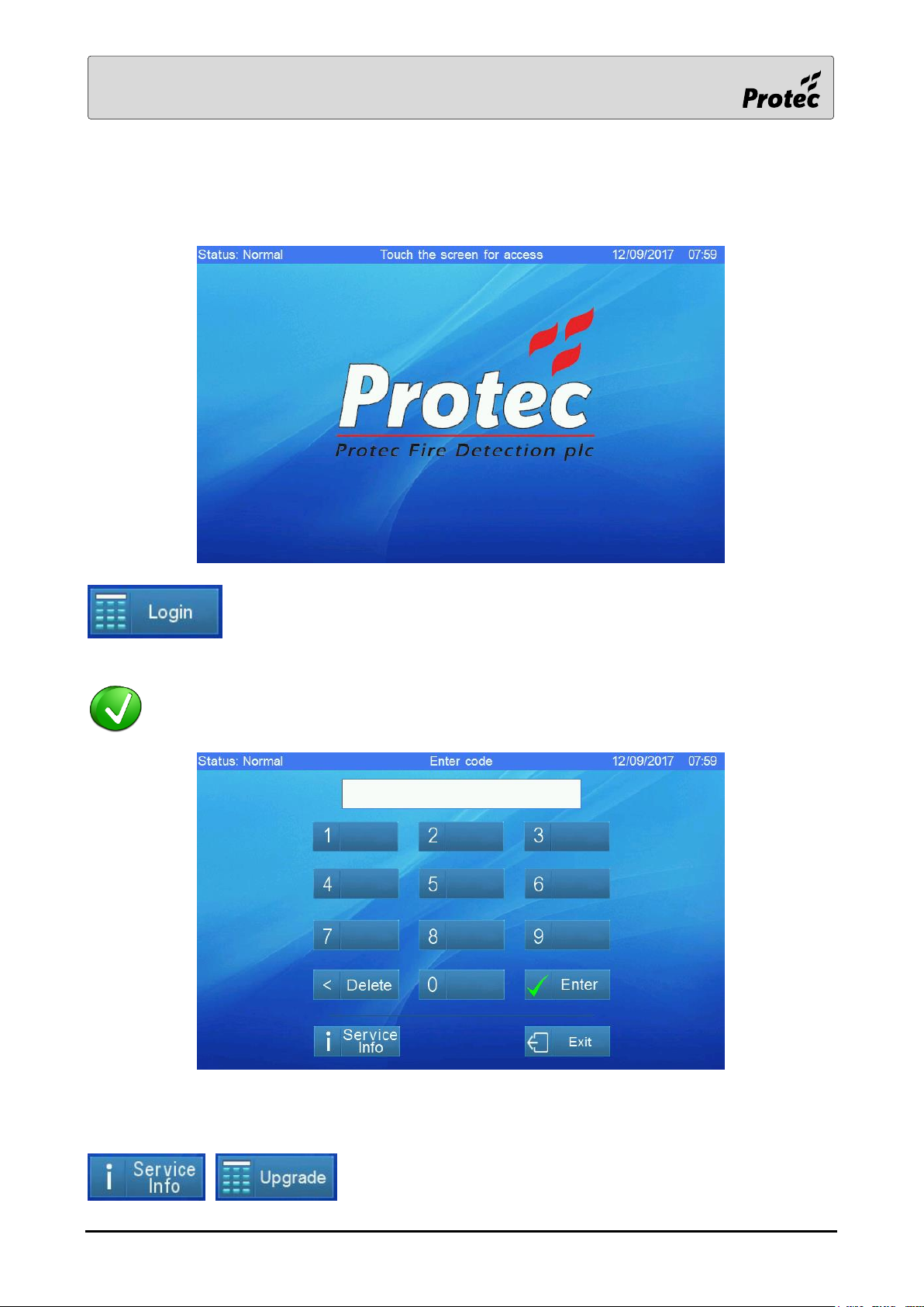
Access to the features of the 6500 is achieved by logging in. If it is displayed, Press
Login and the display will show the code entry screen
If the Login button is not displayed, touch the middle of the screen to bring up the code
entry key pad
Enter the engineer code by touching the relevant number buttons then touch Enter. If the code is
correct then the display will show the main menu screen
For information on the Service Info screen and the Upgrade screen
refer to the relevant sections.
RDM0002/3 Page 6 of 57 © 2015 - 2019 Protec Fire Detection plc
Page 7
1.2 Entering the Menu System
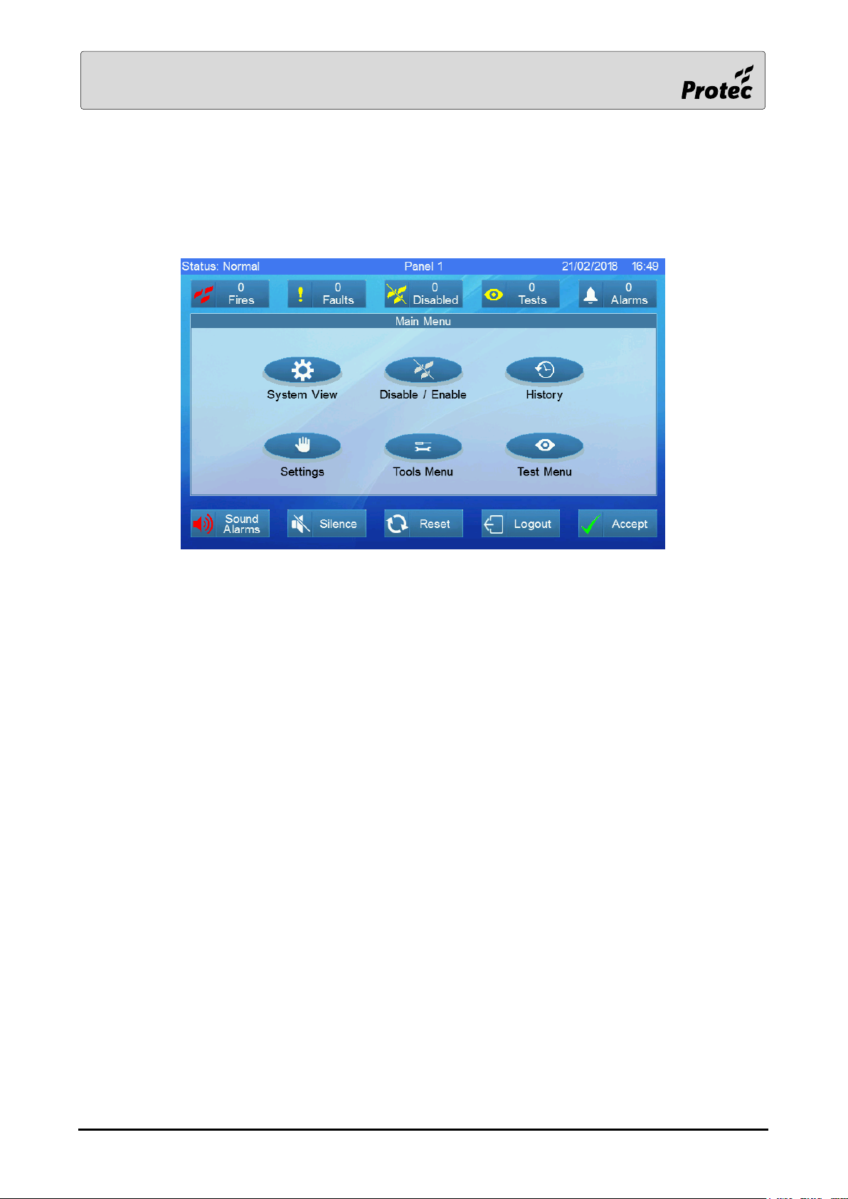
When the engineer code is entered, the ‘Main Menu’ screen will be displayed.
Touch a menu option to select it.
Tools Menu - refer to section 1.3
Test Menu - refer to section 1.17
System View - refer to the user manual
Disable / Enable - refer to the user manual
History - refer to the user manual
Settings - refer to the user manual
RDM0002/3 Page 7 of 57 © 2015 - 2019 Protec Fire Detection plc
Page 8
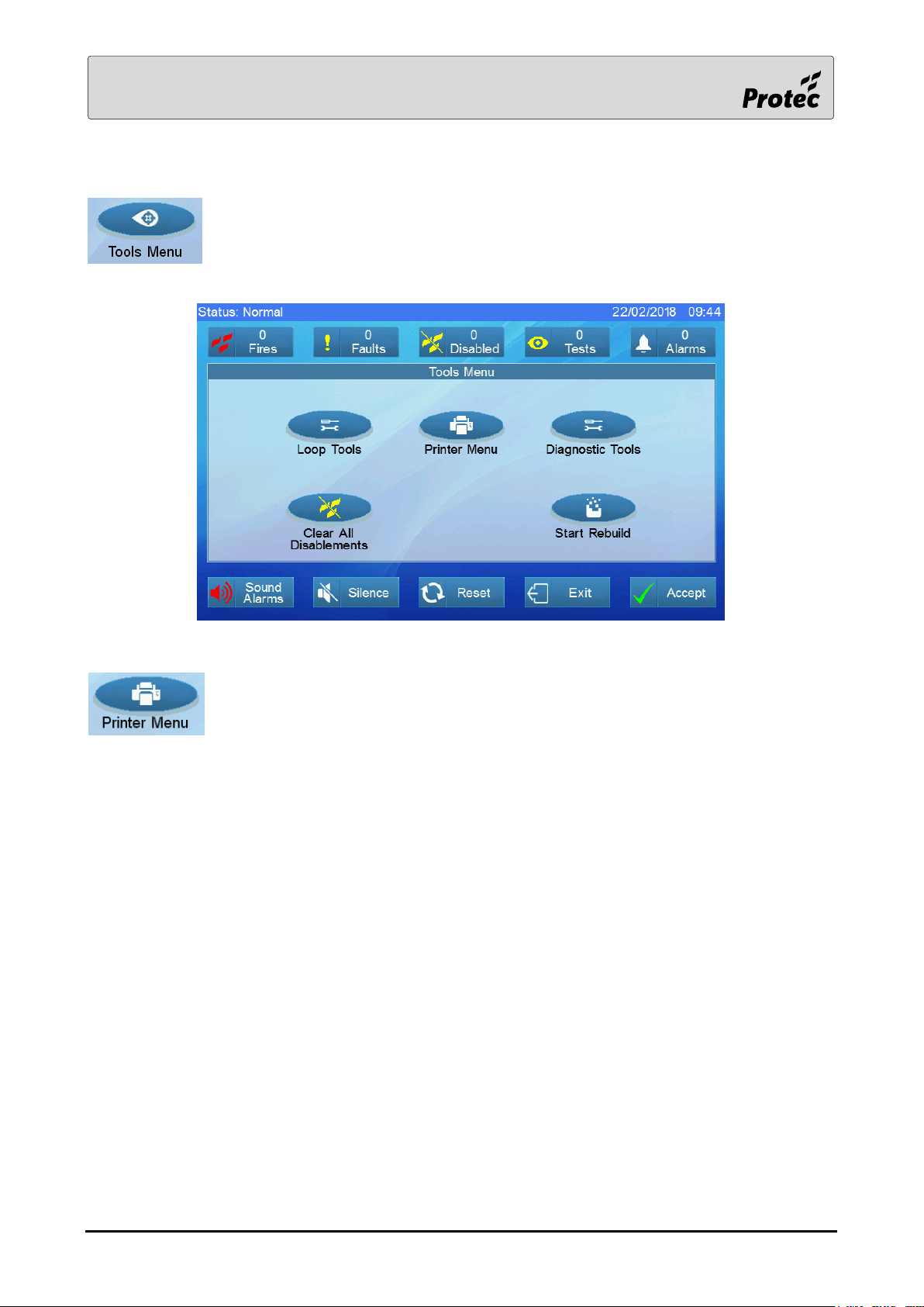
1.3 Tools Menu
Touching Tools Menu displays options to show the commissioning tools
The printer menu is displayed if the configuration file downloaded to the panel
included the printer fitted option.
RDM0002/3 Page 8 of 57 © 2015 - 2019 Protec Fire Detection plc
Page 9
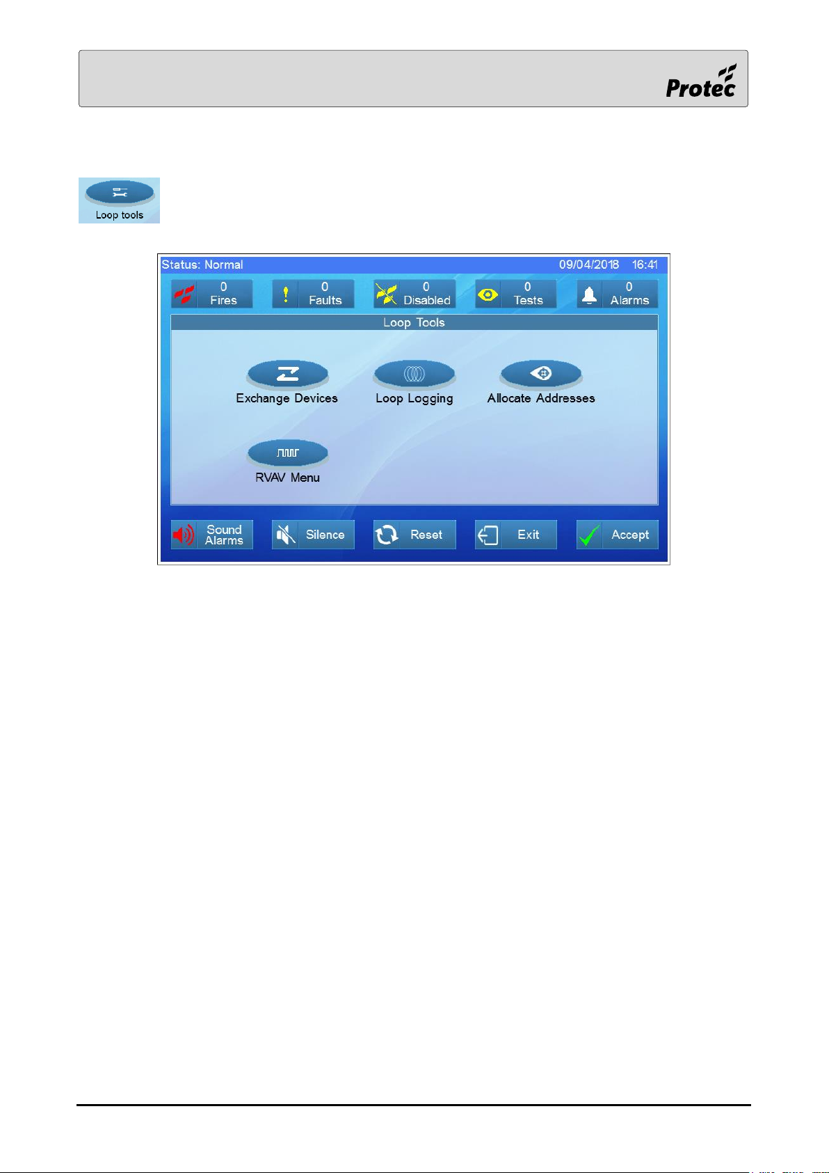
1.4 Loop Tools
Touching Loop tools displays the different loop options.
RDM0002/3 Page 9 of 57 © 2015 - 2019 Protec Fire Detection plc
Page 10
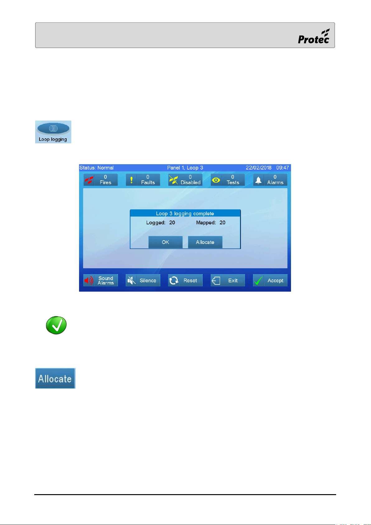
1.5 Loop logging
Each loop must be logged and allocated. Logging finds all the connected devices, their type, software
version and their physical order whilst Allocating allows the engineer to assign an address to each
device. Until a device is allocated an address on the loop, the panel cannot communicate with it.
To log a loop, touch Loop logging to select the panel, then loop card, and then select the
loop.
Loop logging is a two stage process, first it logs how many devices are connected to
the loop then it maps them to find their physical position on the loop. Knowing their
physical position makes fault finding easier. Loop logging can take several minutes; its
progress is indicated on the display.
Touch Allocate to move direct to the allocation menu (see next section) else touch OK
to exit the logging screen.
RDM0002/3 Page 10 of 57 © 2015 - 2019 Protec Fire Detection plc
Page 11
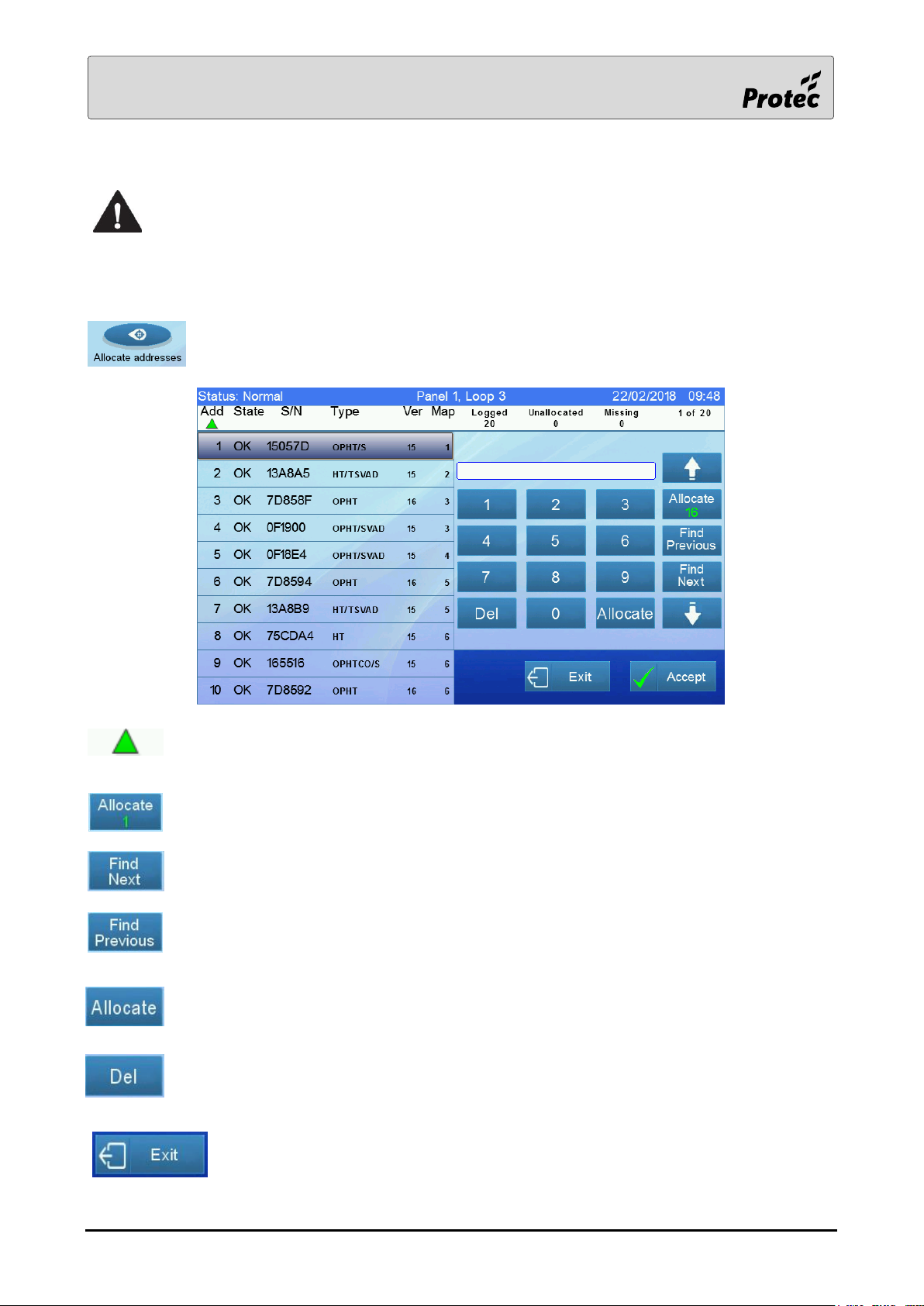
1.6 Allocate Addresses
A loop must be logged before it can be allocated
Each Protec ‘6000’ loop device has a unique serial number. This serial number has to be linked to a
unique address. The process of linking the serial number to an address is known as address allocation.
To begin allocating the device addresses, touch Allocate addresses to select the panel,
then loop card, and then select the loop.
Indicates the column used for sorting the data. Touch one of the other column headers to
change the method of sorting.
This button provides a quick way to allocate the selected device to the lowest unused
address, in this case the address is ‘1’.
This button finds the next device in the list to the one selected that has not yet been
allocated an address.
This button finds the previous device in the list prior to the one selected that has not yet
been allocated an address.
This button allocates the selected device the address that has been entered. The address
range is ‘0’ to ‘200’. Each device must have a unique address between ‘1’ and ‘200’. ‘0’ or a
blank address is used to de-allocate a device.
This button deletes the latest digit that has been entered.
On completion of the address allocation, touch Exit.
RDM0002/3 Page 11 of 57 © 2015 - 2019 Protec Fire Detection plc
Page 12
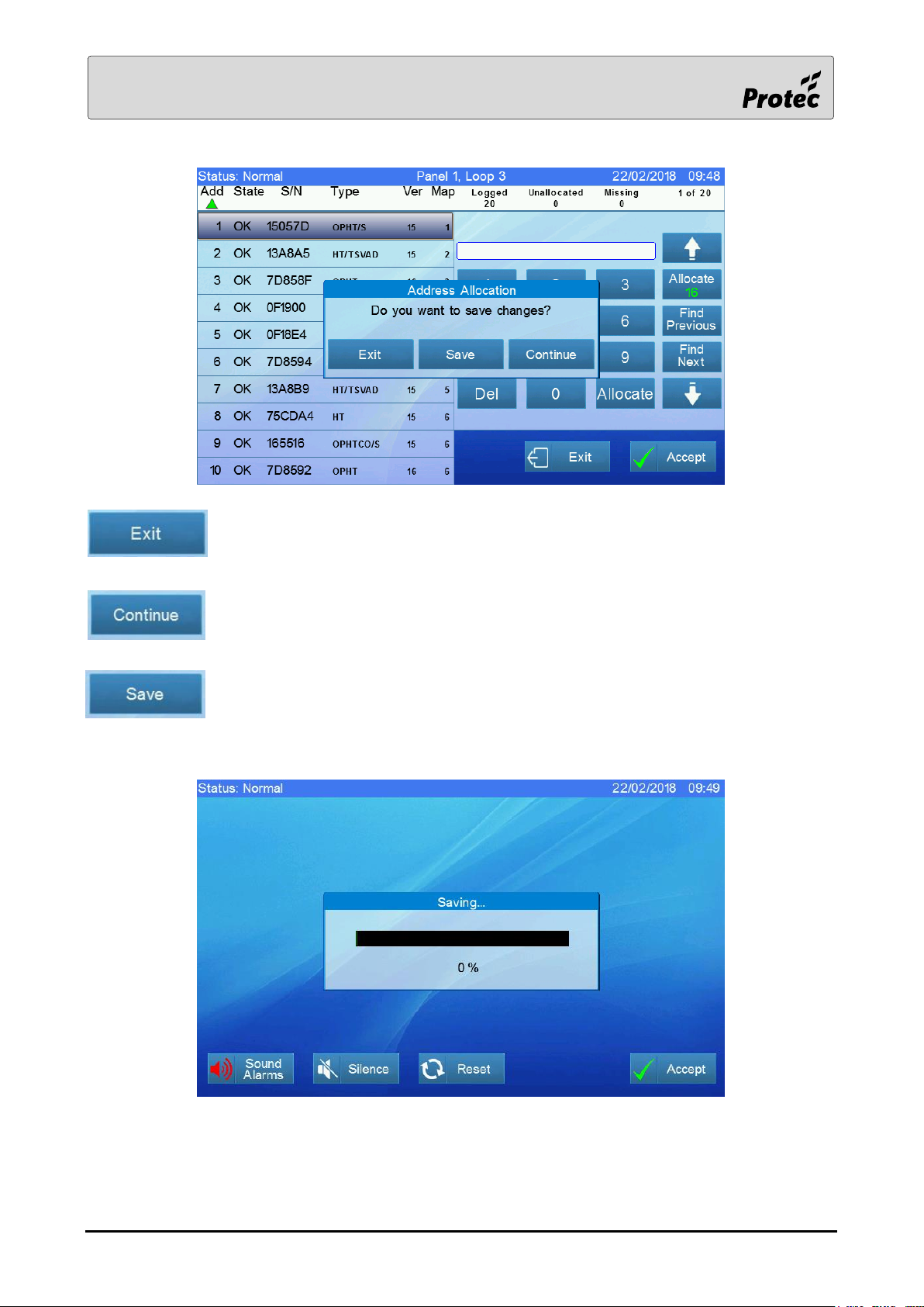
Touch Exit to leave the allocation menu without saving any changes.
Touch Continue to return to the allocation screen.
Touch Save to store the newly allocated data. A progress bar is displayed as shown
below.
RDM0002/3 Page 12 of 57 © 2015 - 2019 Protec Fire Detection plc
Page 13
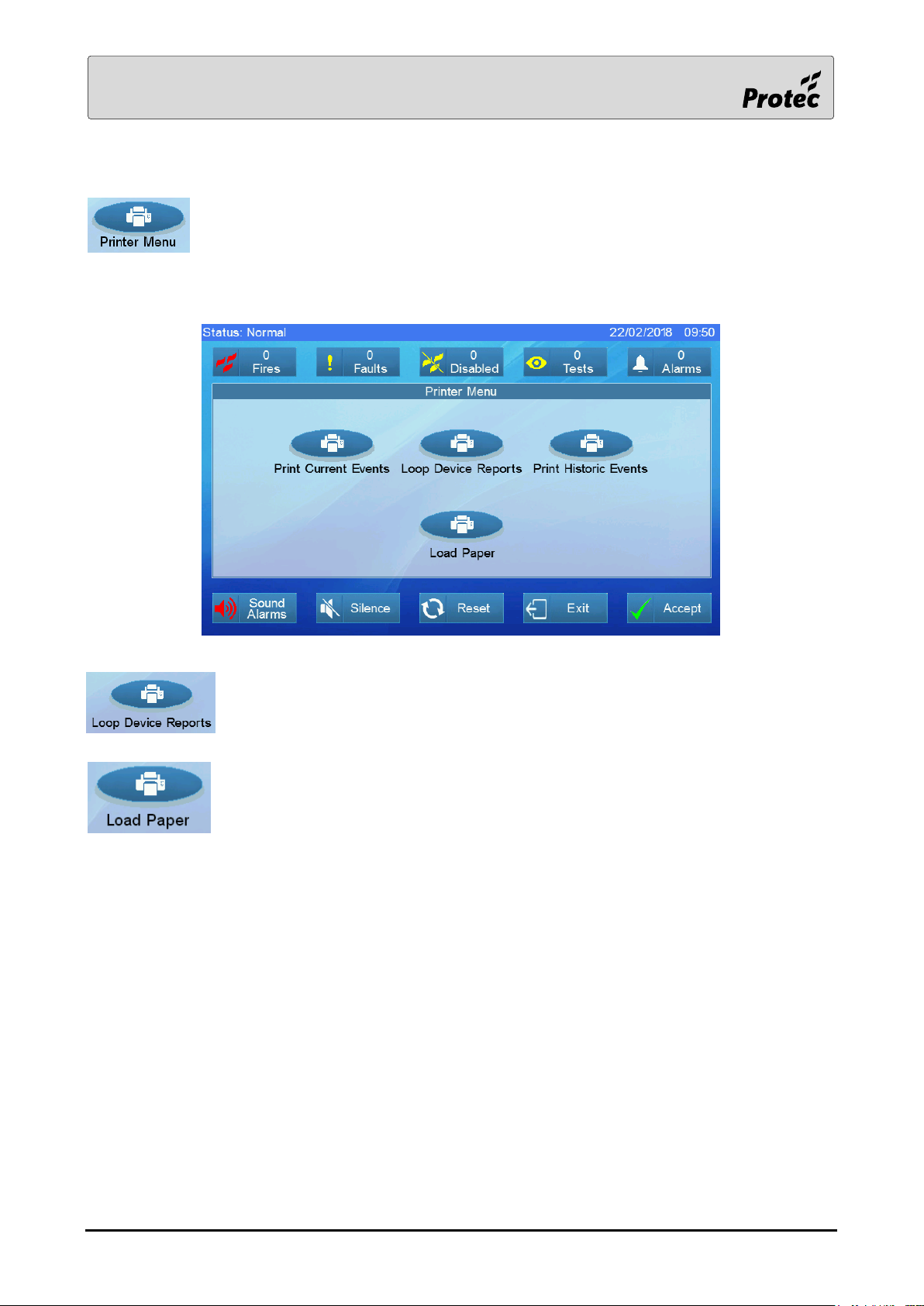
1.7 Printer Menu
Touching Printer Menu displays the printer options.
Note: - The printer menu option is only available on panels configured to have a printer.
Prints Loop Device serial numbers and analogue values after selecting the panel,
the loop card then the loop.
Powers up the printer for a period of time to allow feeding of a new roll of paper.
RDM0002/3 Page 13 of 57 © 2015 - 2019 Protec Fire Detection plc
Page 14
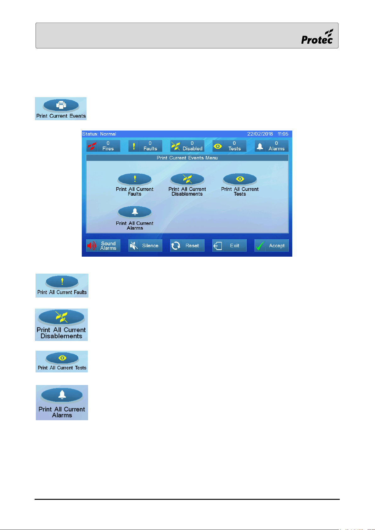
1.8 Print current events
Touching Print Current Events displays the printer options.
Prints the current faults.
Prints the current disablements.
Prints the current tests.
Prints the current alarms.
RDM0002/3 Page 14 of 57 © 2015 - 2019 Protec Fire Detection plc
Page 15
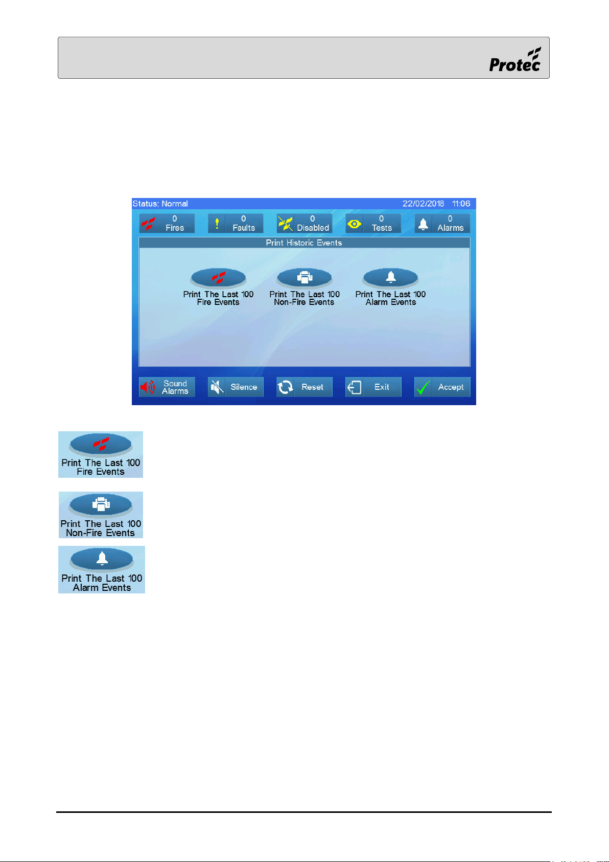
1.9 Print Historic Events
Touching Print Historic Events displays the printer options.
Prints the last 100 Fire events from the historic log.
Prints the last 100 Non- Fire events from the historic log.
Prints the last 100 Alarm events from the historic log.
RDM0002/3 Page 15 of 57 © 2015 - 2019 Protec Fire Detection plc
Page 16
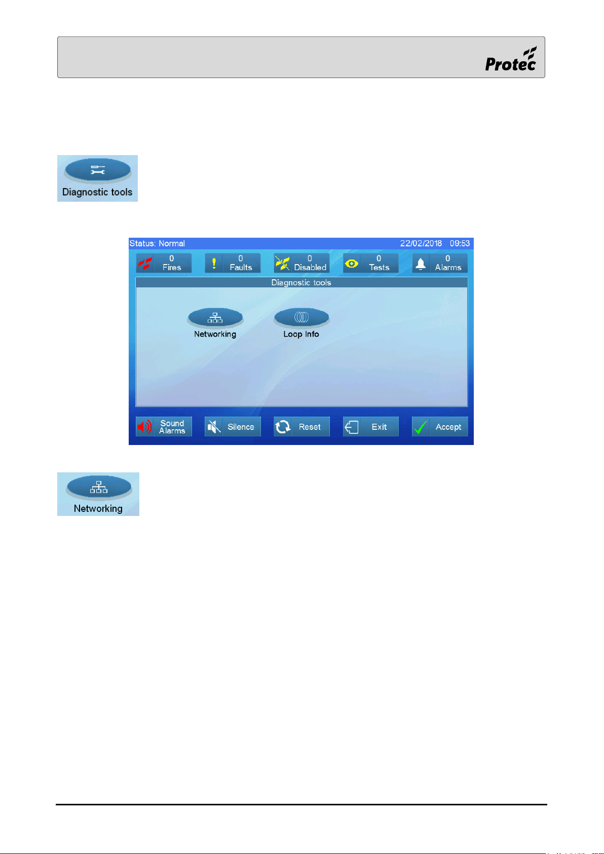
1.10 Diagnostic Tools
Touching Diagnostic tools displays options to show the available tools.
The Networking button is not available on a single panel system.
RDM0002/3 Page 16 of 57 © 2015 - 2019 Protec Fire Detection plc
Page 17
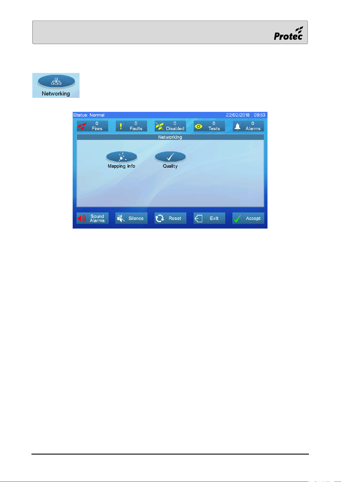
1.11 Networking
Touching Networking displays options to show the network diagnostic tools.
RDM0002/3 Page 17 of 57 © 2015 - 2019 Protec Fire Detection plc
Page 18
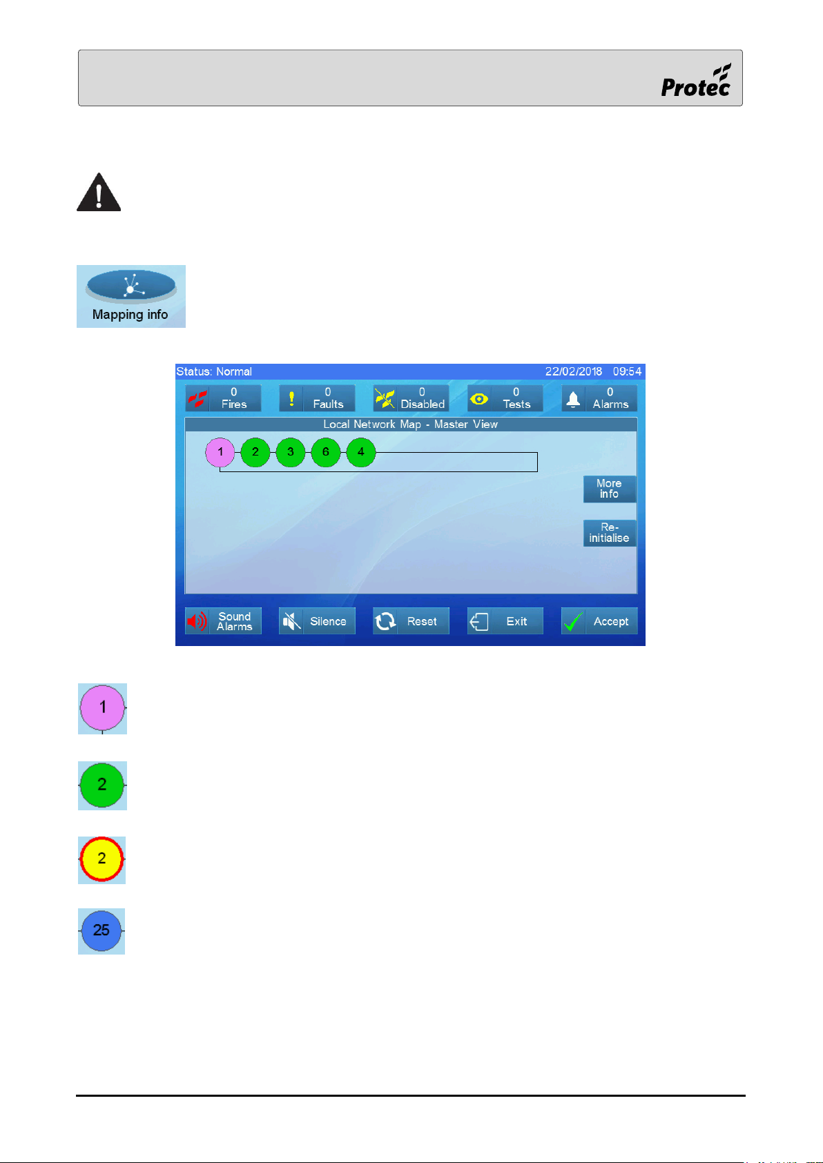
1.12 Mapping Info
To access all the network information, this must be performed on the master panel.
Slave panels are limited to displaying the network map.
Touch Mapping info then select the Network card. This displays a map of the panels
connected to the network and a summary of the number of panels mapped and
missing.
Pink indicates the master panel with no faults
Green indicates a slave panel with no faults
Yellow indicates that the panel has a fault. A red border to the yellow circle indicates that the
panel is one side of a network break.
Blue indicates a slave panel that is acting as the master.
RDM0002/3 Page 18 of 57 © 2015 - 2019 Protec Fire Detection plc
Page 19
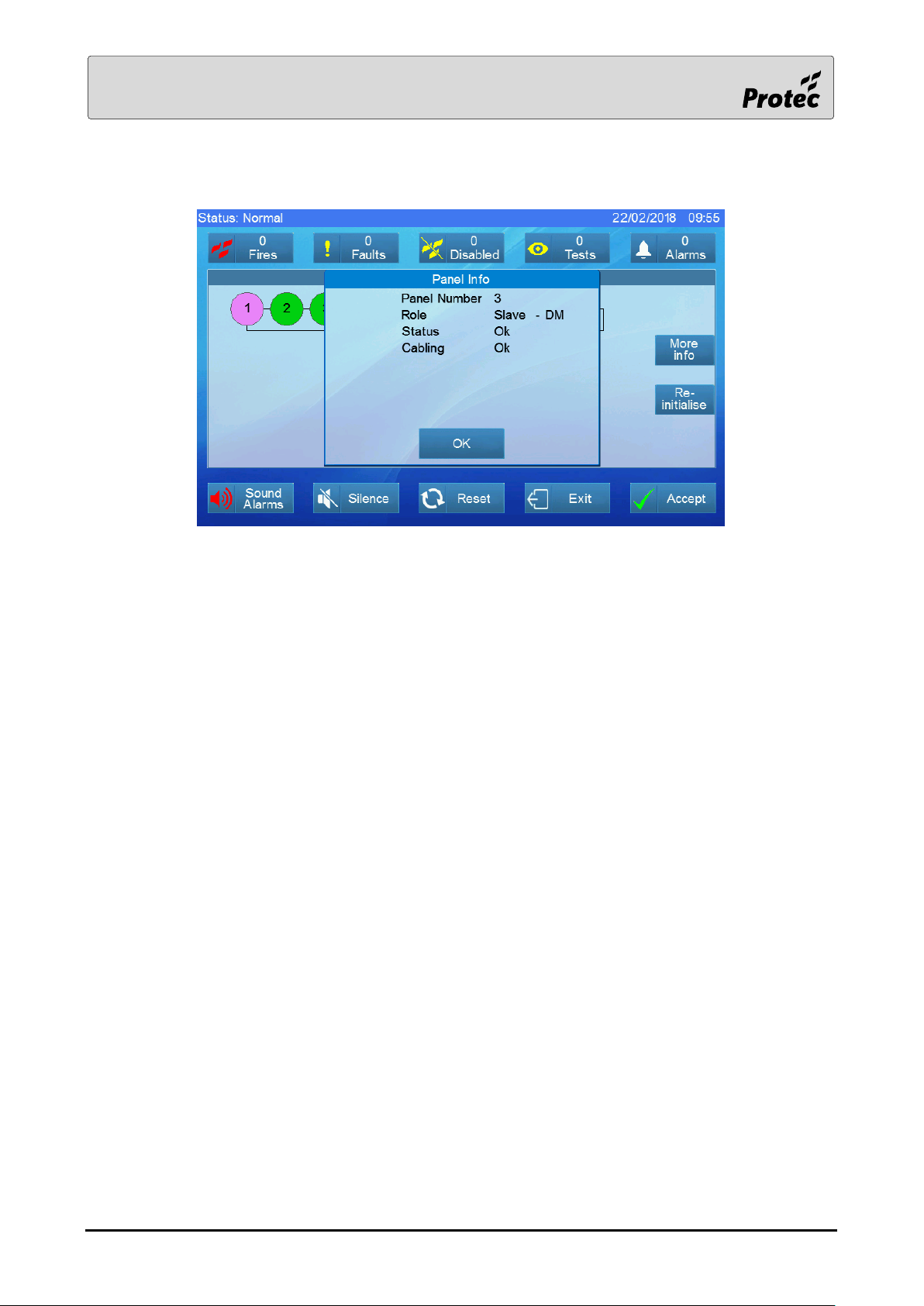
Touch a panel icon to display its details as shown below.
A panel can have one of three roles:
Master – The master manages all network functions
Slave DM – The deputy master assumes control when the master is offline e.g. whilst being
programmed
Slave – A standard remote network panel
Promoted Master – A slave panel that is acting as the master panel
The master panel may display additional fault information to that shown above:-
Fault map error
The panel sequence found does not match the sequence downloaded to the master panel.
Fault network failed
There are too many network problems for the network to function.
Fault duplicate master
When the system was programmed, two panels have been set up as the master panel. Download the
corrected configuration to both panels.
Fault too many nodes
The master panel discovered too many nodes when it initialised the network.
RDM0002/3 Page 19 of 57 © 2015 - 2019 Protec Fire Detection plc
Page 20

The cabling information reports cable break information such as:-
Break, a panel is reporting a cable break
When using a fibre optics unit cabling information reports cable break information such as:-
Break-CH1, a panel is reporting a cable break on network Channel 1
Break-CH2, a panel is reporting a cable break on network Channel 2
The status information reports issues such as:-
Missing, a panel that should be on the network is currently missing
Duplicate, two panels have the same panel number
Unknown, an unknown panel is on the network
Reverse, a panel has its channel 1 & 2 wiring reversed
RDM0002/3 Page 20 of 57 © 2015 - 2019 Protec Fire Detection plc
Page 21
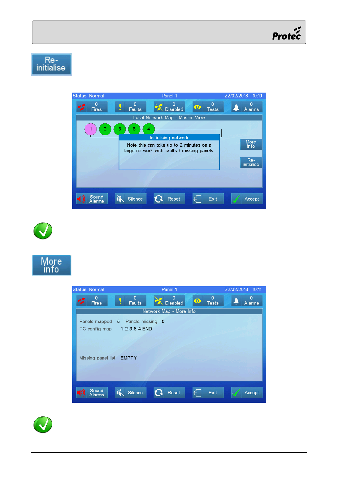
Re-initialise instructs the master panel to re-map the network.
Re-initialise is required when the network is first commissioned or when changes are made.
There should be no further need to re-initialise the network.
More info displays the panel sequence downloaded to the panel.
The panel sequence downloaded to the panel can be compared with the sequence found to
assist fault finding.
RDM0002/3 Page 21 of 57 © 2015 - 2019 Protec Fire Detection plc
Page 22
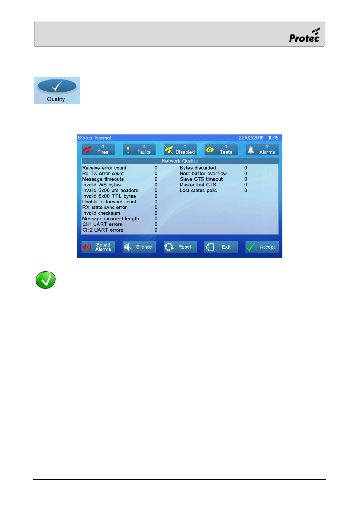
1.13 Quality
Touch Quality then select the network card to display data that the panel has
collected on the operation of the network.
Note: - The quality data can only be cleared by re-initialising the network.
This data is automatically refreshed.
Note: - This data can be used to check for network problems. Leaving the panel for one hour then rechecking
should show no additional CH1 or CH2 UART errors.
RDM0002/3 Page 22 of 57 © 2015 - 2019 Protec Fire Detection plc
Page 23
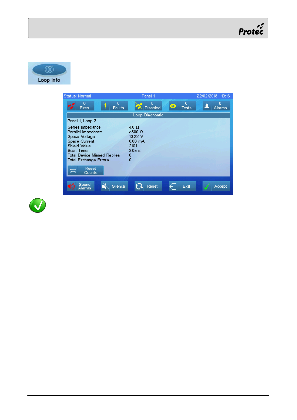
1.14 Loop Info
Touch Loop Info to display the diagnostic information after selecting the loop card
then the loop
This data is automatically refreshed every 30 seconds.
Series Impedance Denotes the total resistance of both the loop positive and negative
conductors. A value greater than 32Ω is considered high. The maximum
permitted resistance is loop specific because it depends upon both the
loop length and current drawn.
Parallel Impedance Denotes the resistance between the loop positive conductor and the
loop negative conductor. This figure would normally be >500Ω.
Space Voltage Denotes the low voltage level of the loop signalling. This voltage will be
around 10V
Space Current Denotes the current drawn during the low voltage level of the loop
signalling. This figure should be almost zero
Shield Value The shield resistance is not measured on a 6500 panel so ignore this
value
Scan Time Denotes the time taken to communicate with every loop device. This
time period varies between 2.5 and 8 seconds
RDM0002/3 Page 23 of 57 © 2015 - 2019 Protec Fire Detection plc
Page 24

Total Device Missed Replies Indicates the number of times that a loop device has failed to reply to
the loop card since the counter was last reset. This figure is an
indication of the quality of the loop signalling. It is recommended that
the counts are reset then the data is checked again an hour later. There
should be no missed replies.
Total Exchange Errors Indicates the number of times that the loop card has failed to
communicate with the loop driver processor. This figure should always
be zero.
Touch Reset Counts to clear the Total Device Missed Replies and the Total
Exchange Errors to zero
RDM0002/3 Page 24 of 57 © 2015 - 2019 Protec Fire Detection plc
Page 25
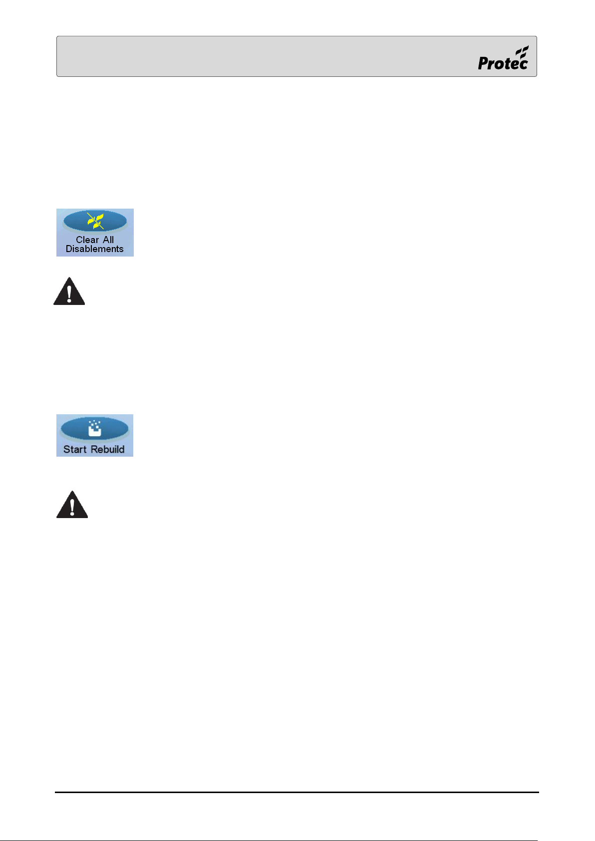
1.15 Clear All Disablements
Each panel stores all of the system disablements. The panels regularly monitor the disablements in
order to ensure that all the panels remain in sync. If a disablement is applied or removed whilst a
panel has been taken offline for reprogramming then when the panel re-joins the network, a
disablement fault will occur. The only way to clear a disablement fault is to ‘Clear All Disablements’ and
then ‘Clear system fault’.
Touching Clear All Disablements will blank all disablements on the system. See note
below regarding key-switch disablements.
If a key-switch, used to generate a disablement, is currently active then, switch it off,
clear all disablements then activate it again.
1.16 Rebuild
Each panel stores all of the faults. Occasionally the panels on a network can disagree about the
number of faults. This can occur if one panel was temporarily isolated from the network.
Touching Start Rebuild will cause each panel to remove all faults except their own.
Each panel will then transmit its own faults on the network. On completion of the
rebuild, all panels will have the same record of all faults.
Unlike the previous Protec 6400 panel, during a rebuild each panel does not regenerate
its own faults. Each panel simply retransmits its own events that already exist in its
database.
RDM0002/3 Page 25 of 57 © 2015 - 2019 Protec Fire Detection plc
Page 26
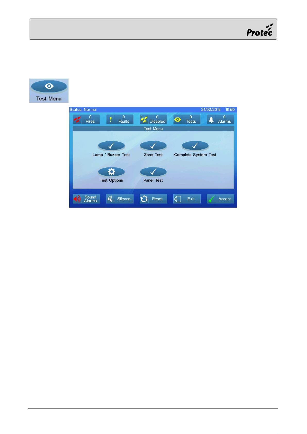
1.17 Test menu
Touch Test Menu to display the different test types
Touch a menu option to select it.
Test Options - refer to section 1.18
Lamp / Buzzer Test - refer to the user manual
Zone Test - refer to the user manual
Complete System Test - refer to the user manual
Panel Test - refer to the user manual
RDM0002/3 Page 26 of 57 © 2015 - 2019 Protec Fire Detection plc
Page 27
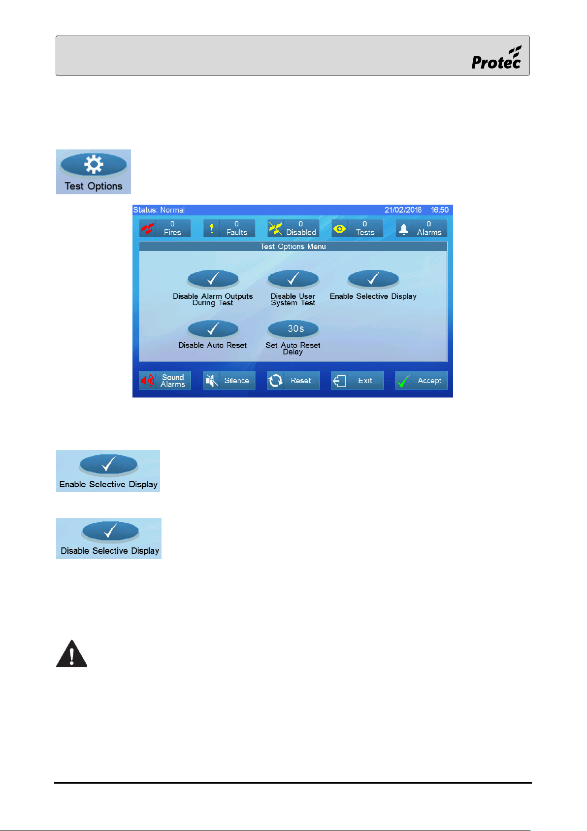
1.18 Test options
Touch Test options to display the test settings available
Note: - Only a single panel on the network may function as a selective display at any time.
Touch to enable the selective display on the current local panel
Touch to disable the selective display anywhere on the network
Enabling the selective display will cause test events to be displayed on only the selective display and
local panel instead of across the entire network.
If the user wishes to use the selective display then the selective display option must be
set before any test events are created.
RDM0002/3 Page 27 of 57 © 2015 - 2019 Protec Fire Detection plc
Page 28
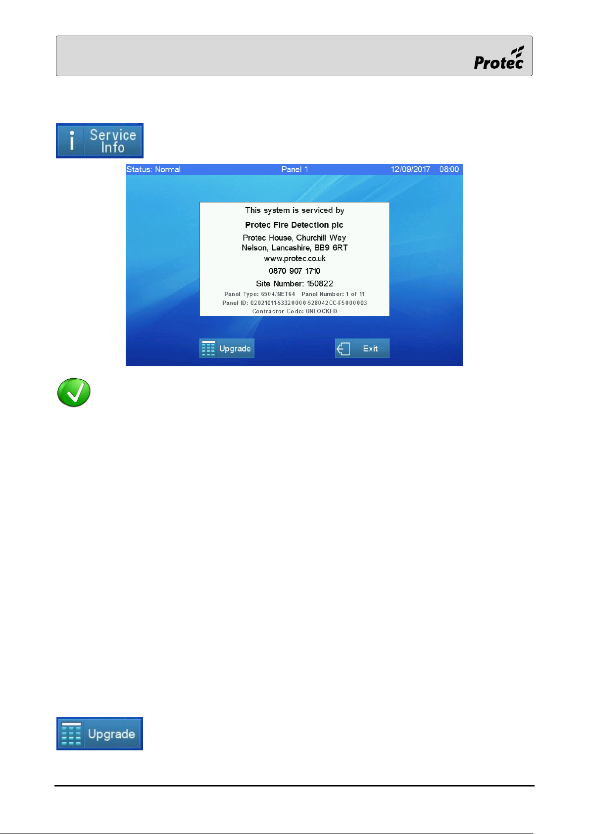
1.19 Service Info
Touch Service Info to display the details of the servicing company and the panel
details
To change the details of the service company displayed here, use the X600 Commissioning
software
Panel Type 65 indicates that this is a 6500 panel
00 indicates that this panel cannot support loops because it is a repeater
01 indicates that this panel can support one loop
02 indicates that this panel can support two loops
04 indicates that this panel can support four loops
NET6 indicates that the network card is suitable to connect to a local network
with up to 6 panels.
NET32 indicates that the network card is suitable to connect to a local network
with up to 32 panels.
NET64 indicates that the network card is suitable to connect to a local network
with up to 64 panels.
Panel Number The panel number provides a quick way to find out which panel number this is
and also how many panels are on the system.
Panel ID The panel ID is the serial number of the controller card in this panel
Contractor Code Unlocked indicates that this panel is Open Protocol
A five digit number indicates the contractor code of the servicing company
It is possible to upgrade a panel to support more loops or to connect to more
network panels. Contact Protec for further details. It is recommended that a
picture of the Service Info screen is emailed to Protec.
RDM0002/3 Page 28 of 57 © 2015 - 2019 Protec Fire Detection plc
Page 29
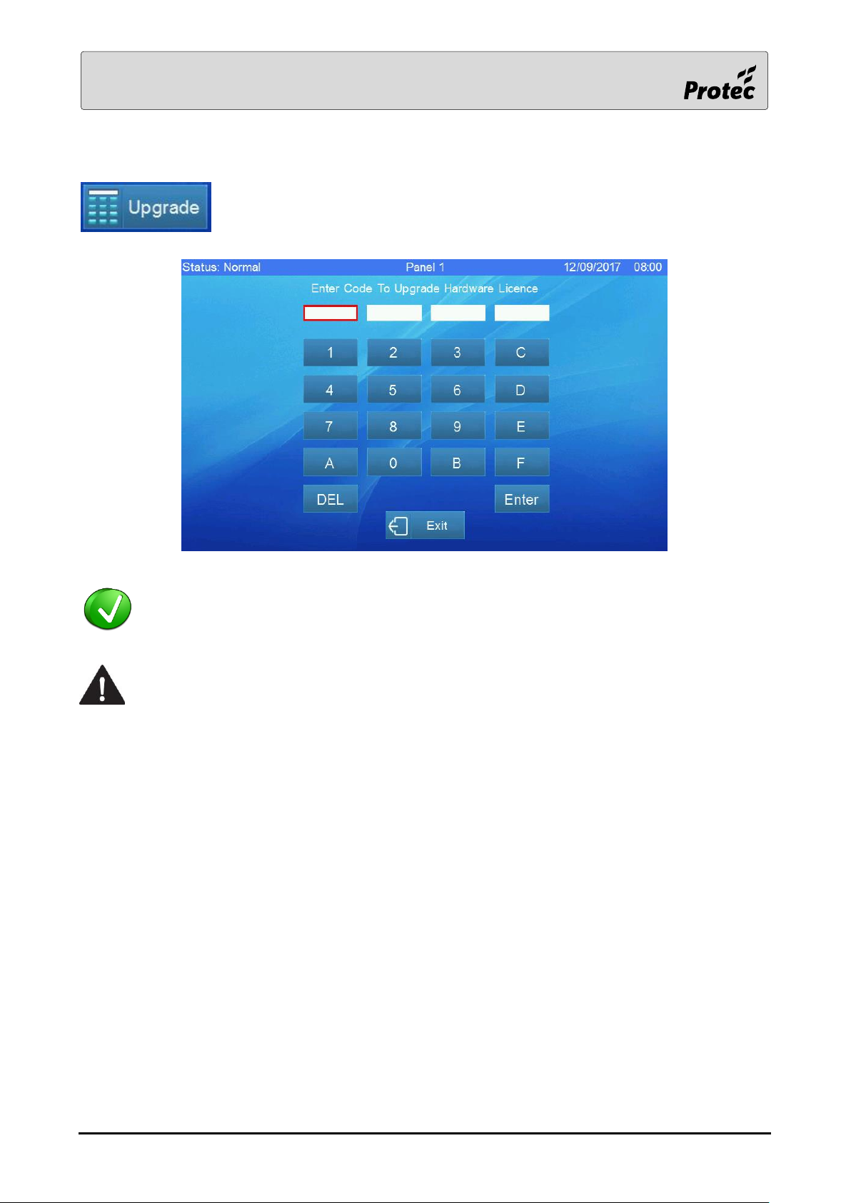
1.20 Upgrade
Touch Upgrade to enter the upgrade code supplied by Protec
Once the upgrade code has been entered, return to the Service Info screen and confirm that
the Panel Type is correct
The upgrade code is valid for a specific date; ensure that you use it on the correct date
and that the panel date and time is correct before you enter the code.
RDM0002/3 Page 29 of 57 © 2015 - 2019 Protec Fire Detection plc
Page 30
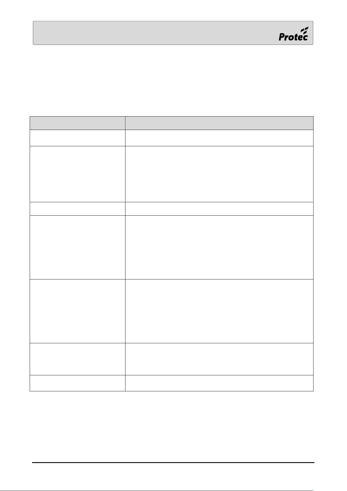
LCD Text
Description
Buzzer Isolated
The buzzer mute switch on the rear of the Display card is in the
wrong state
DLP Card Missing
One of the cards within the panel is not communicating to the
controller card.
1. Check that the cards have been fitted in their correct slots.
2. Review the configuration file
If a mimic controller (Wefa 521) is not communicating.
3. check that the red LED is be On and the green LED is
flashing.
DLP Card Offline
The card has been taken offline probably to be reprogrammed
Power Supply Fault
The panel has a power supply fault.
1. Check that the configuration option ‘Internal PSU fitted’
has been set correctly and downloaded to the panel
2. Use a meter to check the voltage on the ‘SF’ connection.
This should be approximately 12V
3. If the panel has an external PSU, check that both 24V
supplies are connected
4. Check that the temperature lead is fitted to the PSU
RS232 Comms Fault
The RS232 events transmitted by the panel are not being
acknowledged. Check that
1. There is not a break in the cable
2. The baud rate in the configuration file is correct
3. The PC program (or whatever is receiving the data) is
running
If there is no requirement for the RS232 interface, remove it from
the panel’s configuration file
Tamper Fault
Applies to NZ panels only. Indicates that the panel door is closed
and one or both of the following is true :-
1. The SGD is isolated or in test
2. The alarm outputs are disabled
Loop Disablement CRC Fault
There is a conflict between the disablement information held by
the controller card and that held by the loop card
2.0 Fault Events
2.1 Panel faults (Non-latching)
All panel faults include a panel number, some include a card number. If required, refer to the separate
section on DLP card identification.
RDM0002/3 Page 30 of 57 © 2015 - 2019 Protec Fire Detection plc
Page 31
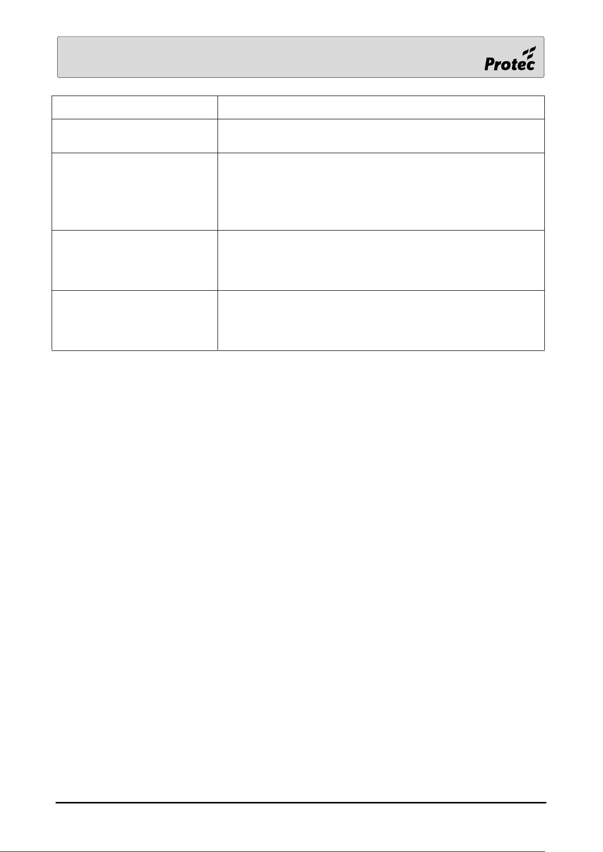
LCD Text
Description
Silence Switch Fault
Applies to NZ panels only. Indicates that the fireman’s silence
keyswitch is active
MIMIC Device Missing
The mimic LED controller bus can support 64 devices. One of
these devices e.g. an MEI board is missing. The reported address
is the device DIL switch address plus one.
In order for a mimic switch device (Wefa 522) to function 5V and
Comms must be connected, the green device LED must be lit.
Deluge Drive Limit Fault
An attempt was made to exceed the number of permitted active
deluge outputs. The panel has restricted the number of active
deluge outputs.
WODU Interface Board Missing
Applies to prison WODU panels only. The WODU interface board
(Wefa 562) that is connected to the display card via the Printer
Data port is not communicating. Check that the green led on the
interface board is flashing.
RDM0002/3 Page 31 of 57 © 2015 - 2019 Protec Fire Detection plc
Page 32
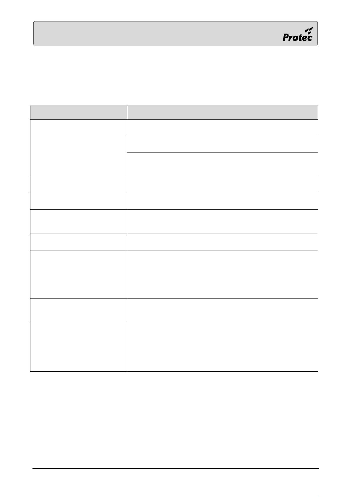
LCD Text
Description
Configuration Error
There was an error in the configuration file when it was
downloaded to the panel
One or more loops has been logged and allocated but the data
has not been uploaded from the panel to the PC
This fault latches and can only be removed by fixing the
configuration error in the Commissioning software and
downloading the corrected configuration to the panel.
DLP Card CRC Error
A card is reporting a corruption in its memory. This card should be
replaced
DLP Card Incorrect Version
One of the cards has out of date firmware and needs to be
updated
Invalid Event
There was a problem transmitting this event on the network.
Refer to the panel number to find the actual event. Report the
problem to Protec
Panel Offline
The panel has been disconnected from the network probably to
be programmed.
Printer Fault
The panel cannot communicate with its printer. Check that 1. the
two printer cables are in place
2. there is sufficient paper
3. there is no paper jam
If there is no printer fitted, remove it from the panel’s
configuration file
System Fault
Faults that are deemed to be system faults will generate a
separate System fault event.
Fix the cause of the problem then press ‘Clear System Fault’.
Network Comms Fault
Every few minutes, the master panel transmits a message to one
of the panels on the system. If this panel fails to reply then a
network comms fault is generated.
Press Reset to clear this fault. If the problem persists then the
fault will be regenerated however the time taken to regenerate
this fault depends upon the number of panels on the network.
2.2 Panel faults (Latching)
All latching panel faults include a panel number, some include a card number. If required, refer to the
separate section on DLP card identification. These faults latch and can only be removed by pressing
reset except where stated.
RDM0002/3 Page 32 of 57 © 2015 - 2019 Protec Fire Detection plc
Page 33
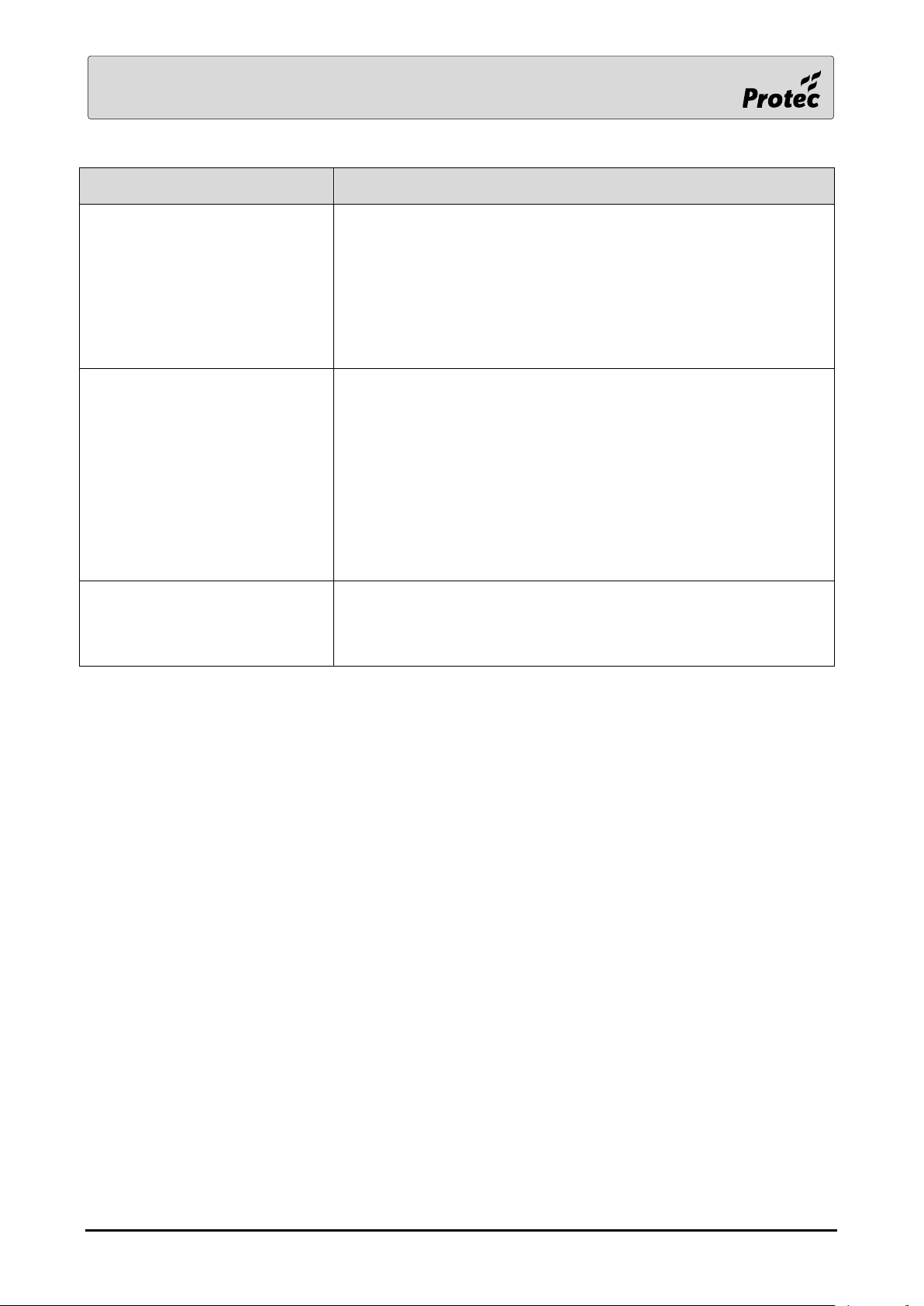
LCD Text
Description
Disablement Fault
Every few minutes, the master panel transmits the disablement
information to the other panels on the system. If one of those
other panels discovers that the received information does not
match its own information then this fault is reported.
To remove this fault :-
1. From the Tools menu, press ‘Clear All Disablements’
2. Press Reset
3. From the Settings menu, press ‘Clear System Fault’
Internal Error – System DB
Indicates that the system database is filling up.
Contact Technical @ Protec
a) Upload the fire & non-fire databases from each panel that
is reporting the fault using a PC program supplied by
Technical. Note that the historic log is not to be confused
with the database
b) The fault can only be cleared by taking the panel offline
and back online
c) Once the database is full, the panel cannot function
correctly
Internal Error – DLP Queue
Indicates that the system failed to send information to a loop card
a) The fault can only be cleared by taking the panel offline
and back online
If the fault persists, contact Technical @ Protec
RDM0002/3 Page 33 of 57 © 2015 - 2019 Protec Fire Detection plc
Page 34

LCD Text
Description
Licence Fault 0x0001
There is a serial number mismatch between the display card and
the controller card. This indicates that one of the cards has been
swapped for a replacement.
To remove the fault :-
a) Replace the original card and if necessary cycle the power
off and back on
b) If a new card has been purchased then contact the
supplier for an upgrade code.
c) Enter the upgrade code
Only one licence fault can be generated by a panel at a time.
Other licence faults may be present.
Licence Fault 0x0002
There is a network configuration issue. This indicates that more
than six panels are in the network configuration file and the panel
generating this fault is only licensed for a six panel network.
To remove the fault :-
a) If more than six panels have been included in the
configuration in error then remove the incorrect panel,
rebuild the configuration file and download it.
b) Contact the panel supplier for details of how to upgrade a
panel.
Only one licence fault can be generated by a panel at a time.
Other licence faults may be present.
Licence Fault 0x0003
There is a network map issue. This indicates that more than six
panels are in the network map received from the network card
and the panel generating this fault is only licenced for a six panel
network.
To remove the fault :-
a) If more than six panels have been connected in error then
remove the extra panel and if necessary cycle the power
off and back on
b) Contact the panel supplier for details of how to upgrade a
panel.
Only one licence fault can be generated by a panel at a time.
Other licence faults may be present.
RDM0002/3 Page 34 of 57 © 2015 - 2019 Protec Fire Detection plc
Page 35
LCD Text
Description
Network Comms Fault
See section 2.2 for details
Network – Break
Panel X – Panel Y
There is a break in the network between Panel X and Panel Y
where X and Y are the panel numbers
Network Card Flash Checksum
Fault
There is a memory corruption in the network card, replace the
card
Network Card Isolated
The network card is not communicating with the network, check
that switch 1 is off
Network - CH2 PSU Fault
There is a fault in the network card’s isolated power supply,
replace the card
Network - Configuration Fault
The configuration data received by the network card is corrupt
Network - Duplicate Master
Two master panels have been detected on the network. There are
two possible causes:
1. Two panels have been assigned as the master in their
configuration data. This needs correcting using the PC
commissioning software
2. During a double break of the network wiring, two panels have
to perform the job of master. On restoration of the network,
one of these has failed to relinquish control of the network. Reinitialise the network at the original master panel
Network - Duplicate Panel(s)
The network has initialised with two panels that have the same
number. This needs correcting using the PC commissioning
software. Note that neither panel is allowed to transmit an event
so each will eventually display a Slave CTS fault
Network - Failed
The network is not operational because there are too many faults
Network Fault - Network Master
Elected
The network has unexpectedly lost the master panel so another
panel has automatically been assigned as the master until the
problem is fixed
Network – Map Fault
The physical order of the panels does not match the order
downloaded to the master panel
Network – Missing Panel
One or more panels in the master panel’s network configuration
data is missing.
Network - Reverse Wiring Fault
One or more panels has its network CH1 and CH2 wiring reversed
Network - Slave CTS Fault
The panel has an event to transmit but the network master panel
is not permitting it to transmit. This fault will be reported by
duplicate panels.
Network - Too Many Panels
The network has initialised with too many panels. The network
supports a maximum of 64 panels
Network - Unknown Panel(s)
The network has initialised with a panel that is not in the master
panel’s network configuration data
2.3 Network Faults
All network faults include a panel number
Network faults latch and can only be removed by pressing Reset
RDM0002/3 Page 35 of 57 © 2015 - 2019 Protec Fire Detection plc
Page 36
LCD Text
Description
Network - CH1 Shutdown Fault
A network fault has occurred causing the panel to ignore data
from network CH1
Network - CH2 Shutdown Fault
A network fault has occurred causing the panel to ignore data
from network CH2
Network - I2C Link Fault
The communications link between the local network card and
the core network card is faulty
Network - RS485 CH1+ Partial O/C
There is a high resistance in the CH1+ cable
Network - RS485 CH1- Partial O/C
There is a high resistance in the CH1- cable
Network - Running On Processor B
Processor ‘B’ is the backup processor and is only used when
processor ‘A’ has failed
Network - Short A Leg To B Leg
There is a short circuit fault in the network between CH1+ and
CH1-
Network - Short A Leg To Screen
There is a short circuit fault in the network between CH1+ and
the screen
Network - Short B Leg To Screen
There is a short circuit fault in the network between CH1- and
the screen
The following network faults are not available in some panel options.
RDM0002/3 Page 36 of 57 © 2015 - 2019 Protec Fire Detection plc
Page 37
LCD Text
Description
Loop Drive Open Circuit
The loop has a break in its wiring. The fault threshold is currently set
to 100Ω
Loop Drive Overload Fault
The loop cannot be driven due to an overload condition.
Loop Drive Parallel Fault
There is a low resistance between loop ‘+’ and loop ‘-‘. The fault
threshold is currently set to 200Ω (Issue E) or 120Ω (Issue F). This
fault will also occur if more than ten loop device repeater LEDs are
turned on at the same time
Loop Drive Series Fault
There is a high resistance in the loop wiring. The fault threshold is
currently set to 80Ω (Issue E) or 50Ω (Issue F) however any value
greater than 32 is considered high. The loop current calculator in
the commissioning software must be used to determine if the
system has been designed correctly.
For export customers who use loops for detection devices only,
there is an option to ignore this fault. Users of the option take
responsibility for checking that the loop devices function correctly.
This checking includes correct operation at low battery voltage
levels or when there is a loop open circuit.
Loop Drive Short Circuit
The loop has a short in its wiring. This fault is probably :-
1. in the wiring between loop side ‘A’ and the first device with
an isolator
2. in the wiring between loop side ‘B’ and the last device with
an isolator
Loop Drive Processor Fault
The loop driver processor has reported a fault.
1. The panel reporting the fault must be taken offline then
back online to clear this fault
2. Report this fault to Technical @ Protec
2.4 Loop faults
All loop faults include a panel and loop number.
All Loop faults latch and can only be removed by pressing Reset.
RDM0002/3 Page 37 of 57 © 2015 - 2019 Protec Fire Detection plc
Page 38
LCD Text
Description
Loop Card Processor Fault –
0xabcd
The loop card processor has reported a fault.
1. The panel reporting the fault must be taken offline then
back online to clear this fault
2. Report this fault to Technical @ Protec along with the
number ‘abcd’
Unknown Active Device
This fault normally occurs during commissioning and indicates that
a device that hasn’t been allocated onto the loop has an active input.
Only MCPs and interface devices eg MICCO, MIP, ZAI, 16 Way boards
etc can cause this fault.
Detectors and sounders cannot cause this fault.
If this fault occurs on a live site that has already been commissioned
then :-
1. Check the loop diagnostic data for problems including
missed replies.
2. Put the loop into exchange device mode then press Reset.
This would reveal an added device if one was present.
This fault could increase the time taken for an MCP or other loop
device to generate a fire signal.
This fault was previously displayed as ‘Loop Drive VPI Fault’
Loop Initialisation Fault
The loop has failed to initialise correctly. None of the devices on the
loop may function correctly.
This fault can be caused by the loop being disabled because the
panel is not licensed to run the loop. If this is the case then there will
be no voltage on the loop. Use the Service Info screen to check the
panel type and confirm the number of licensed loops.
LCD Text
Description
Loop Drive Shield Fault
There is a cable break in the loop shield. This fault can only occur
on a 6600 panel
The following loop faults are not available in some panel options
RDM0002/3 Page 38 of 57 © 2015 - 2019 Protec Fire Detection plc
Page 39
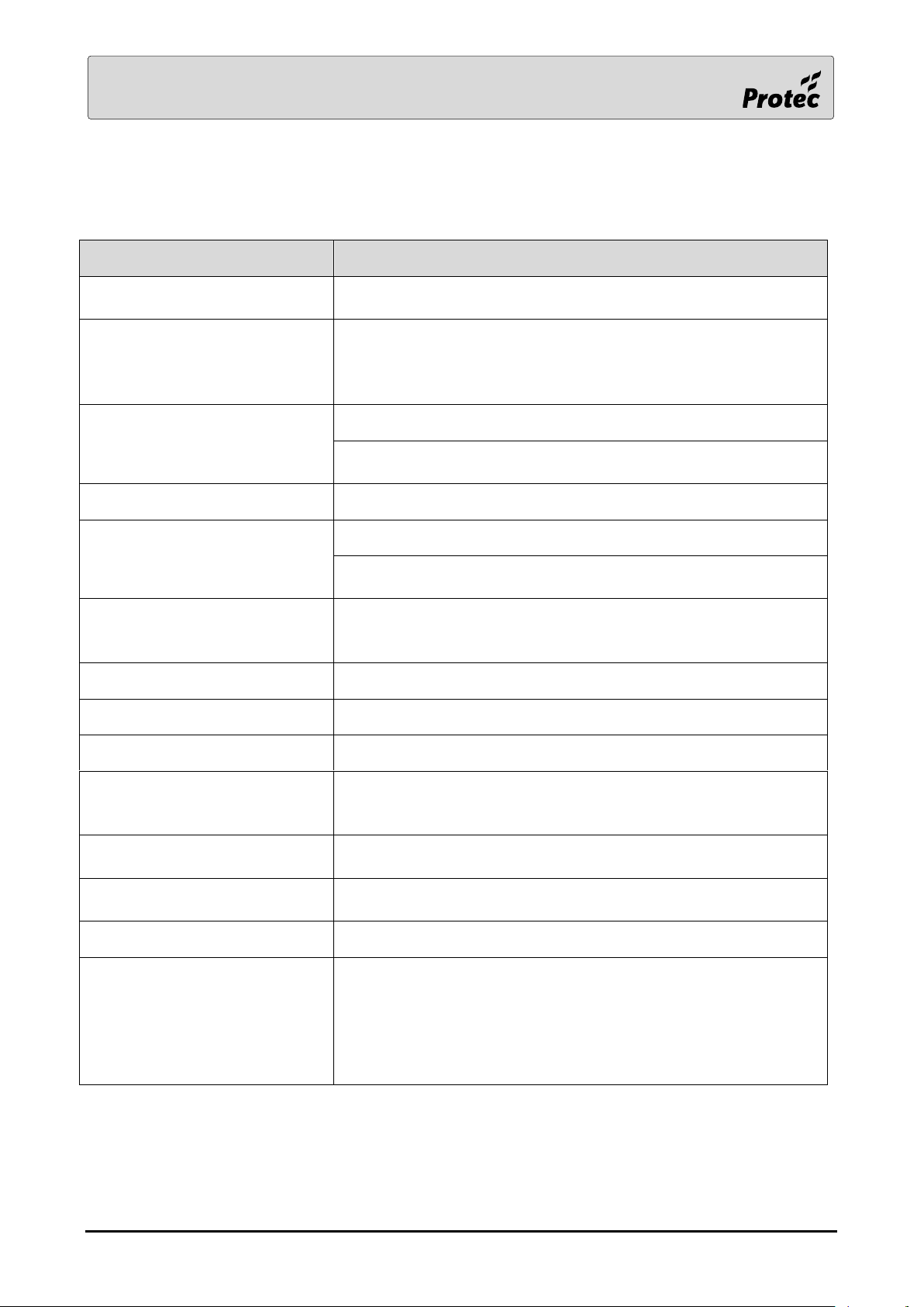
LCD Text
Description
Alarm Fault
A device with a relay or sounder output has reported a fault e.g.
16Way
Device Added Fault
An unallocated device is on the loop. The panel will report the
device type and serial number. Up to eight devices per loop can
be reported as added. This fault is latching until the panel is
reset.
Device Fault
A loop device has reported a fault
A 16 Way board has a local supply monitor fault. This can only be
reported by the first address of the 16 Way board
Device CO Sensor Fault
The CO sensor in the device has a fault
Device Failed Setup
The device did not initialise correctly.
To remove the fault and re-initialise the device, remove the
device for 60 seconds then replace it
Device Invalid Sensitivity
The sensitivity, or alternate sensitivity, programmed for this
device is incorrect. Review the settings for this device in the
commissioning software
Device Open Circuit
The device is reporting an open circuit at its input e.g. 16Way
Device Pre-Alarm Fault
The loop device has reached a pre-alarm condition
Device Short Circuit
The device is reporting a short circuit at its input e.g. 16Way
Device Type Fault
The panel reports that the device is the wrong type. This fault is
rare and is more likely caused by poor loop communications. Use
the diagnostic tools to check the loop info for missed replies.
Input Open Circuit
The device e.g. MIP has a break in its monitored input circuit.
Typically the end of line resistor is missing
Input Short Circuit
The device e.g. MIP has detected a short in its monitored input
circuit.
Loop Device missing
The loop device is not replying to the loop card
Output Group Fault
There has been a problem programming the device output
group. To remove the fault :-
1. Press Reset or
2. Remove the device, wait till the panel reports it missing
then replace it.
If the problem persists, replace the device
2.5 Loop Device faults
All loop device faults include a panel, loop, address and zone number along with the device type
RDM0002/3 Page 39 of 57 © 2015 - 2019 Protec Fire Detection plc
Page 40
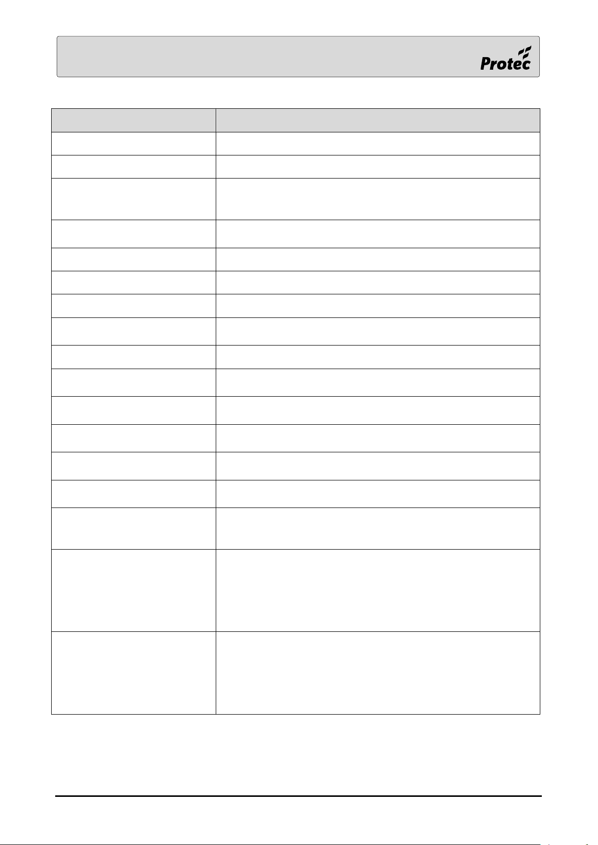
LCD Text
Description
Zone O/C + Alarm Fault
The device, typically a ZAI, has two faults
Zone S/C + Alarm Fault
The device, typically a ZAI, has two faults
Zone Trans Fault
1. A ZAI device is reporting the loss of zone communications
probably caused by the auxiliary 24V supply missing.
2. An LCM device is reporting a tamper fault.
Device Battery Fault
A wireless device is reporting that either its main battery is low or
its standby battery is low
Device Tamper Fault
A wireless device is reporting a tamper fault
Device Pipe Fault
Reported by a Cirrus or Propoint device
Device General Fault
Reported by a Cirrus or Propoint device
Damper Fault
The damper interface unit (DIU) is reporting a damper monitoring
fault or a combination of faults. Refer to PID 243
Damper Supply Fault
The damper interface unit (DIU) is reporting a supply fault
Damper Switch Fault
The damper interface unit (DIU) is reporting a problem with its
limit switch monitoring. Refer to PID 243
Closed Switch Fault
The damper control module (DCM) is reporting a problem with its
closed switch monitoring eg missing EOL resistor
Open Switch Fault
The damper control module (DCM) is reporting a problem with its
open switch monitoring eg missing EOL resistor
Open Switch Position Fault
The damper control module (DCM) is reporting that its actuator
should be in the open position but it isn’t.
Closed Switch Position Fault
The damper control module (DCM) is reporting that its actuator
should be in the closed position but it isn’t.
Supply Out Fault
The damper control module (DCM) is reporting a problem with its
outgoing supply. This is probably caused by a blown fuse in the
DCM.
Position Fault
For a three position damper, the damper control module (DCM) is
reporting that its actuator should be in the set point position but
it isn’t.
For a two position damper, the damper control module (DCM) is
reporting that its actuator is in the opposite position to its
intended position.
DCM Supply Fault
The damper control module (DCM) is reporting a problem with its
incoming supply. This is caused by one of the following :-
The power supply is missing (24V dc or 230V ac)
An open circuit at the Fault Input terminals
This is not a DCM fault and the cause of the missing power supply
should be investigated.
RDM0002/3 Page 40 of 57 © 2015 - 2019 Protec Fire Detection plc
Page 41
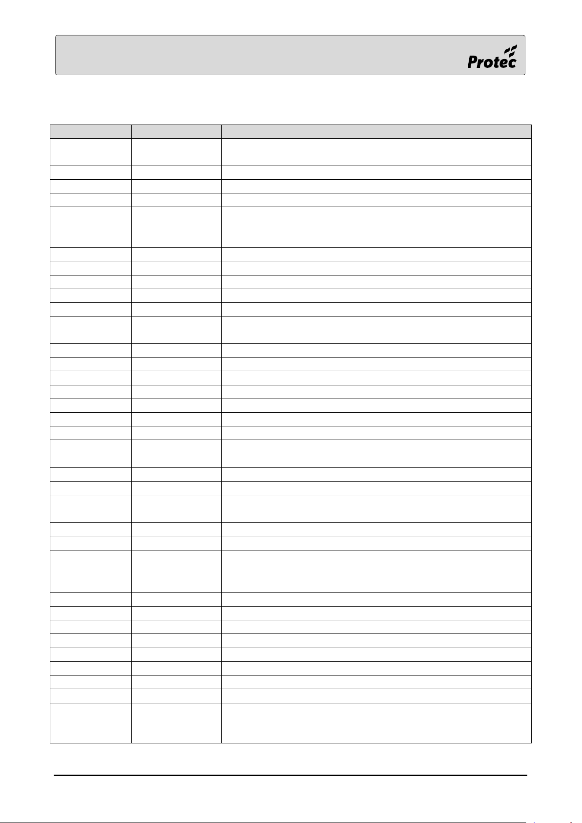
Type
Analogue Value
Notes
MICCO &
4 Way MICCO
17
Short circuit on the input
18
Open circuit on the input (cannot see 47K EOL)
85
Normal
220
Alarm ( 330R ) – Device LED switched ON
MIP &
4 Way
MIPCCO
10
Tamper fault on the Magnetic Interface (Anti-ligature detector) Special
17
Short circuit on the input
18
Open circuit on the input (cannot see 47K EOL)
85
Normal
200
Pre-alarm ( 22K )
220
Alarm ( 1K ) – Device LED switched ON
16 Way 16 PAI
& 16 FRI
10
Supply voltage below 13V
11
O/C Zone, Alarm fault and local supply fault
12
S/C Zone, Alarm fault and Local supply fault
14
O/C Zone and Local supply fault
15
S/C Zone and local supply fault
16
Local supply fault (only applies to first address)
17
S/C Zone fault
18
O/C Zone fault
19
Alarm fault (cannot see 47K EOL)
20
Alarm fault and S/C Zone fault
21
Alarm fault and O/C Zone fault
85
Normal
218
Zone fire, Alarm fault and local supply fault – Device LED
switched ON
219
Zone fire and Alarm fault – Device LED switched ON
220
Zone fire – Device LED switched ON
ZAI, LP ZAI
4 Way ZAI
& 4W LP ZAI
16
Replace the device
17
Zone short circuit
18
Zone open circuit (cannot see 8K2 or capacitive EOL)
19
Alarm fault (cannot see 10K EOL)
20
Zone short circuit and alarm fault
21
Zone open circuit and alarm fault
22
Loss of zone comms eg aux 24V
85
Normal
219
Fire and alarm fault – Device LED switched ON
220
Fire – Device LED switched ON
2.6 6000 Digital Device Fault Information
RDM0002/3 Page 41 of 57 © 2015 - 2019 Protec Fire Detection plc
Page 42
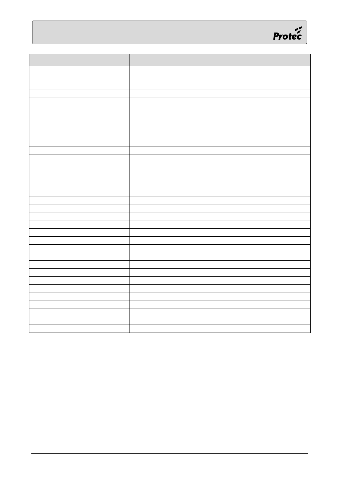
Type
Analogue Value
Notes
LCM (Mutable
ZAI)
PCB WEFA 429
192
Normal ie not isolated and not muted
- 128
Isolated ie user has pressed mute button but LCM is not in alarm
- 64
Muted ie user has pressed mute button whilst LCM is in alarm
+ 32
Automatic Device Fire
+ 16
MCP Fire
+ 8
Zone O/C
+ 4
Zone S/C
+ 2
Alarm fault (cannot see 10K EOL)
+ 1
Tamper fault
Evac Mimic
PCBs
WEFA 320
+ WEFA 319
Reply byte 1
CH1
Use ‘Device Data’ in Engineer menu to obtain the analogue value
Link ENB to 0V for the inputs to be used
5
Normal (PSU+4 = +5 = 0V, Evac Groups 49 – 64)
21
Normal (PSU+3 = 0V, Evac Groups 65 – 80)
37
Normal (PSU+3 = +5 = 0V, Evac Groups 81 – 96)
53
Normal (PSU+3 = +4 = 0V, Evac Groups 97 – 112)
69
Normal (PSU+3 = +4 = +5 = 0V, Evac Groups 113 – 128)
81
Normal (PSU+6 = 0V, Display Groups 129 – 192)
83
Normal (PSU+6 = +7 = 0V, Display Groups 193 – 255) LED 256 is lit
!
84
PSU Fault (or PSU link to 0V missing)
85
Normal (Evac Groups 1 – 16, Display Groups 1 – 64)
87
Normal (PSU+7 = 0V, Display Groups 65 – 128)
93
Isolate Input Active
101
Normal (PSU+5 = 0V, Evac Groups 17 – 32)
117
Normal (PSU+4 = 0V, Evac Groups 33 – 48)
Reply byte 2
CH2
Use ‘Device Data’ in Engineer menu to obtain the analogue value
128
Normal
RDM0002/3 Page 42 of 57 © 2015 - 2019 Protec Fire Detection plc
Page 43
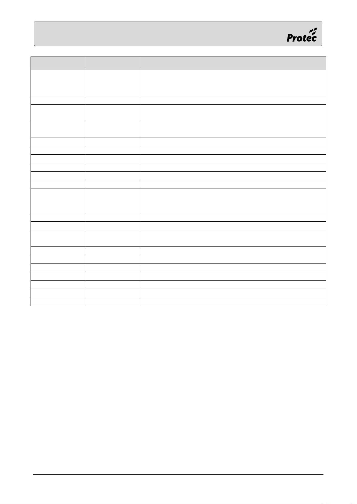
Type
Analogue Value
Notes
CPRO I/F
aka MUX I/F
PCB WEFA 329
Reply byte 1
CH1
Use ‘Device Data’ in Engineer menu to obtain the analogue
value
Particle level
Typically less than 10
ALWAYS CHECK THE CIRRUS UNIT TO CONFIRM THE ACTUAL
UNIT STATUS
Reply byte 2
CH2
Use ‘Device Data’ in Engineer menu to obtain the analogue
value
0
Normal
4
Fault or external (K/S) Disable
5
Airflow fault
6
External (K/S) Isolate
12
System fault
16
Pre-alarm
32
Fire level 1
A single fire signal is generated irrespective of which of the
three fire levels is signalled by the CPRO (standard software)
64
Fire level 2
128
Fire level 3
Reply byte 3
CH3
Use ‘Device Data’ in Engineer menu to obtain the analogue
value
Sum the bits to equal the analogue value
0
None of the faults below are present
2
Water fill fault or no water
16
Expansion board fault
32
LED fault
64
PSU or battery fault
128
Vacuum, sample, purge or chamber seal fault
RDM0002/3 Page 43 of 57 © 2015 - 2019 Protec Fire Detection plc
Page 44
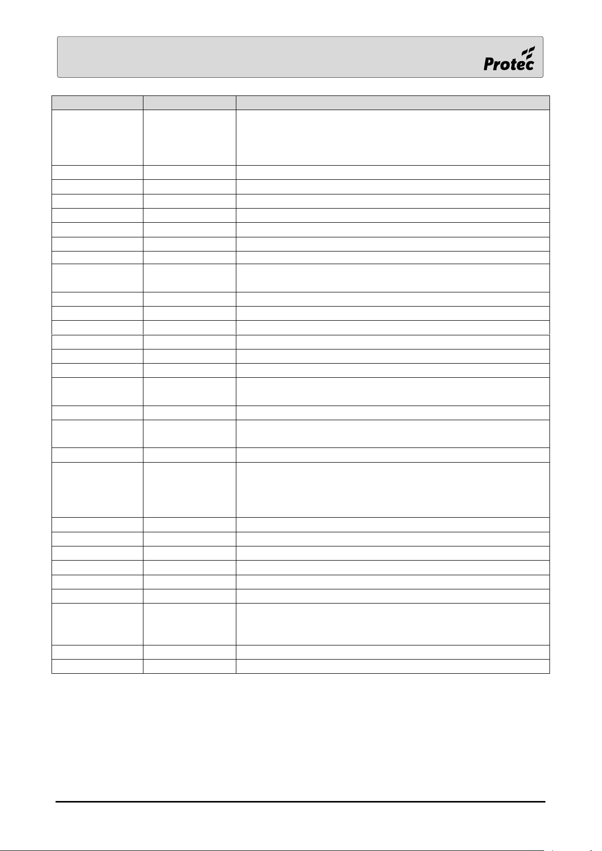
Type
Analogue Value
Notes
Cirrus Hybrid
Type 0x33
& Propoint Plus
Type 0xCE
Reply byte 1
CH1
Use ‘Device Data’ in Engineer menu to obtain the analogue
value
Fire level
85
Normal
86
Pre-alarm
87
Fire level 1
88
Fire level 2
89
Fire level 3
ALWAYS CHECK THE UNIT TO CONFIRM THE ACTUAL UNIT STATUS
Reply byte 2
CH2
Use ‘Device Data’ in Engineer menu to obtain the analogue
value
Bit 0
System fault
Bit 1
Pipe fault
Bit 2
Pipe disabled
Bit 3
Pipe initialising
Bit 4
Pipe airflow fault
Bit 5
Unit Supply fault (indicated for all pipes)
Bit 6
Pipe isolated (indicated for all pipes because the unit is
isolated)
Bit 7
No water (indicated for all pipes)
Reply byte 3
CH3
Use ‘Device Data’ in Engineer menu to obtain the analogue
value
Analogue Value
Sprinkler
Panel
PCB
WEFA 300
81
Input 6 shorted – Disable Fire Link
84
Input 4 shorted – Disable Alarm Outputs
85
Normal reply
87
Input 5 shorted – Disable Control Outputs
93
Input 3 shorted – Disable All (Not used by the 6400)
100
Input 1 shorted – Reset
No change
Input 2 shorted – Lamp Test
Propoint
PCB
WEFA 414
4
Air flow fault device 1
8
Air flow fault device 2
85
Normal
RDM0002/3 Page 44 of 57 © 2015 - 2019 Protec Fire Detection plc
Page 45
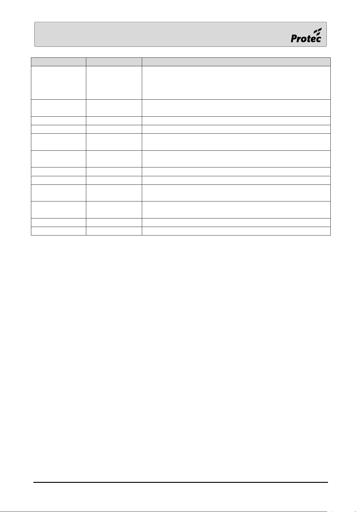
Type
Analogue Value
Notes
Damper I/F
(DIU)
PCB
WEFA 361
Reply byte 1
CH1
Use ‘Device Data’ in Engineer menu to obtain the analogue
value
128
Normal (or damper has failed to operate after its output group
is activated)
+ 1
External supply missing
+ 2
Damper circuit fault eg damper not connected
+ 4
Upper limit switch in wrong state (or open and there is a
monitoring fault)
+ 8
Lower limit switch in wrong state (or open and there is a
monitoring fault)
+ 16
lower limit switch monitoring fault
+ 32
Upper limit switch monitoring fault
+ 64
Damper operated (its output group may not have been
activated)
Reply byte 2
CH2
Use ‘Device Data’ in Engineer menu to view the analogue value
(decimal)
8 Way DIL Switch Value – ‘H’ is the msb, ‘A’ is the lsb
Refer to PID 243 for the 24V dampers
RDM0002/3 Page 45 of 57 © 2015 - 2019 Protec Fire Detection plc
Page 46
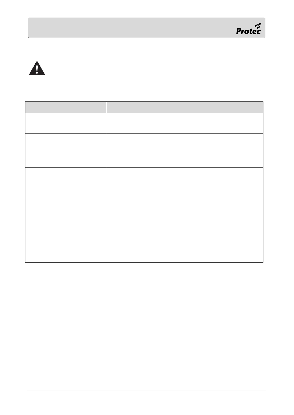
LCD Text
Description
Alarm Routing Fault
There is a fault in the Fire Link output. The 4k7 end of line
resistor is probably missing. The voltage should be
approximately minus 3V in normal operation
Fire Protection Fault
There is a fault in the sounder output designated as the Fire
Protection output. The end of line resistor is probably missing
IO Card Over Current Fault –
Sounder Output n
There is an overload fault in one of the sounder outputs on the
terminal board. ‘n’ indicates the output number. This fault occurs
when the sounder circuit is active.
IO Card Open Circuit Fault –
Sounder Output n
There is an open circuit fault in one of the Alarm Outputs on the
terminal board. The 10k end of line resistor is probably missing.
‘n’ indicates the alarm output number
IO Card Open Circuit Fault –
Fault Link Output
There is an open circuit in the fault link output on the terminal
board. Check that either a 1K end of line resistor or the WEFA 490
EOL pcb is fitted. If the output is not used then it can be disabled
in the commissioning software.
The 6600 terminal board has a dedicated Fault Link Output. The
6500 Terminal board has to designate one of the sounder output
circuits if this feature is required.
IO Card Short Circuit Fault – Aux
24V Output n
There is a short circuit fault in one of the Aux 24V outputs on the
terminal board. ‘n’ indicates the output number
IO Card Short Circuit Fault –
Sounder Output n
There is a short circuit fault in one of the sounder outputs on the
terminal board. ‘n’ indicates the output number
2.7 IO faults
On a new commission, check that the correct panel type has been selected before
attempting to fix IO faults.
All IO faults include a panel number.
RDM0002/3 Page 46 of 57 © 2015 - 2019 Protec Fire Detection plc
Page 47
LCD Text
Description
General Alarm
A general alarm type event has been activated
Technical Alarm
A technical alarm type event has been activated
Tamper Alarm
A tamper alarm type event has been activated
DLP Card address number
Description
2
Core network card
3
IO card
4
Loop card 1&2
5
Loop card 3&4
6
Local Network card
7
Display card
16 - 20
Mimic LED Controller 1 - 5
21 - 28
Zone Expansion 1 - 8
2.8 Alarm events
All alarm events include a panel, loop number and address. A reset is required to remove these
events.
2.9 DLP Card Identification
RDM0002/3 Page 47 of 57 © 2015 - 2019 Protec Fire Detection plc
Page 48
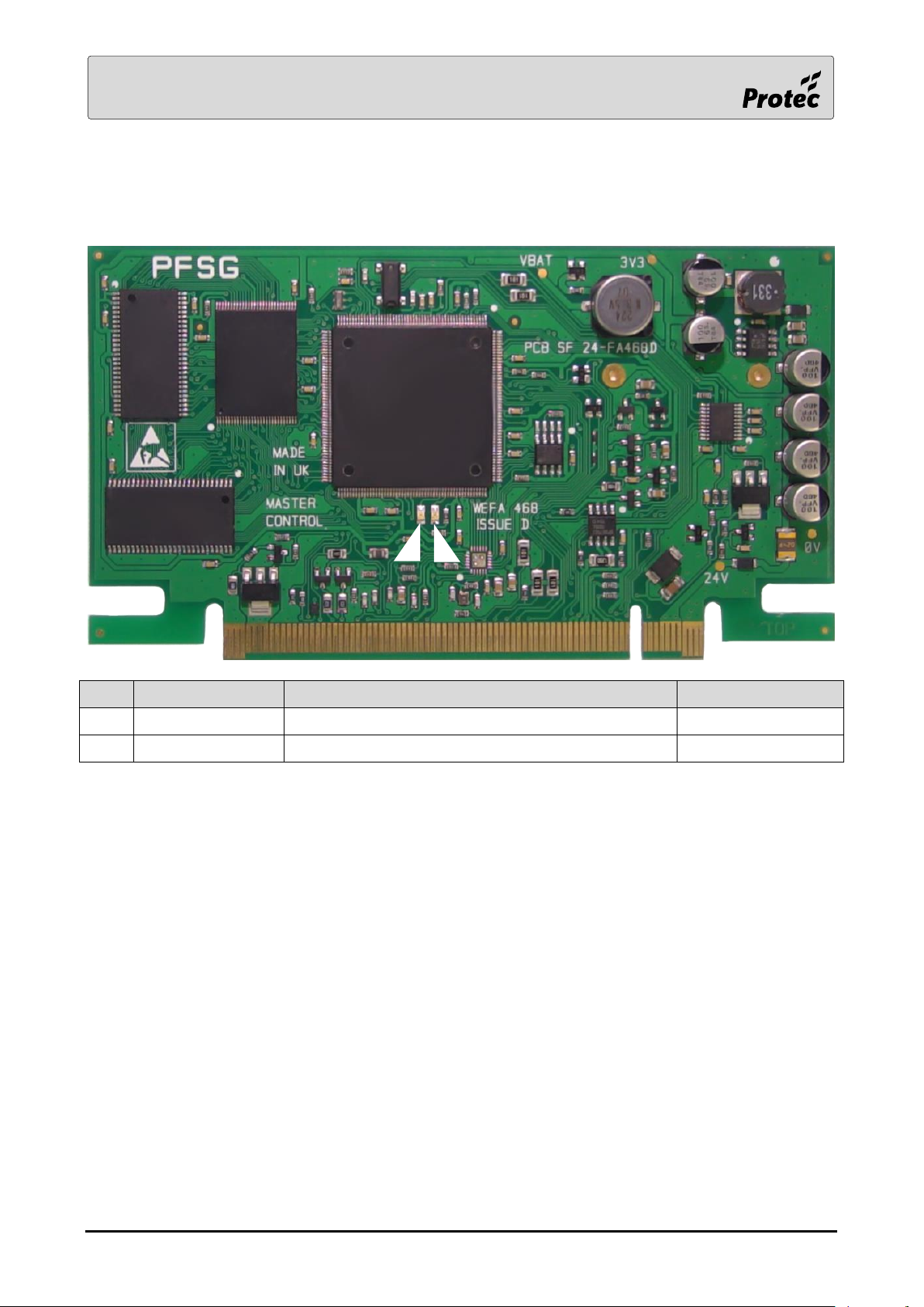
Item
Function
Description
Normal Operation
1
Power LED
Indication to show the card is powered
Solid Red
2
Run LED
Indication to show the card is communicating
Flashing Green
1
2
3.0 Card Hardware Indications
3.1 System Controller Card
RDM0002/3 Page 48 of 57 © 2015 - 2019 Protec Fire Detection plc
Page 49
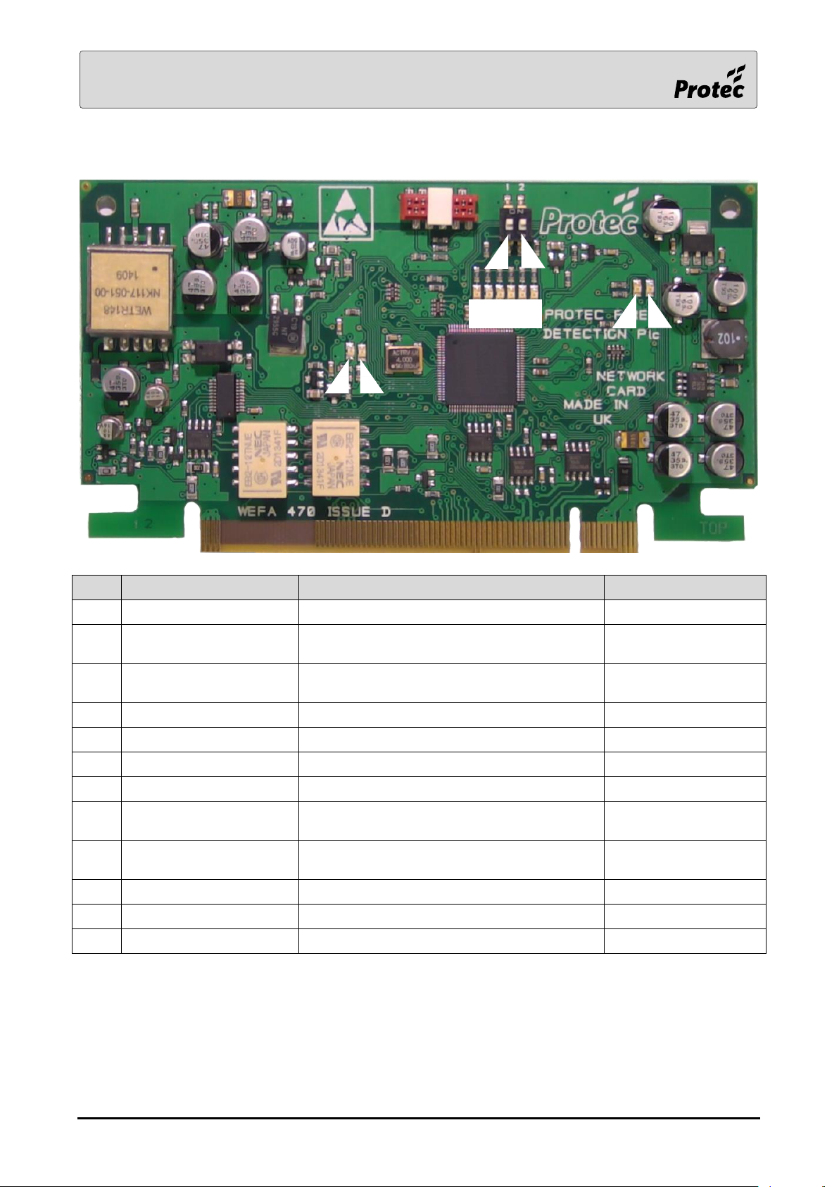
Item
Function
Description
Normal Operation
1
TX Channel 1
Flash every transmission on network CH1
Rapid Flashing Red
2
TX Channel 2
Flash every transmission on network CH2
Occasional Flashing
Green
3
RX Channel 1
Flash every reception on network CH1
Occasional Flashing
Yellow
4
RX Channel 2
Flash every reception on network CH2
Rapid Flashing Yellow
5
Processor A
Network is controlled by processor A
Solid Green
6
Processor B
Network is controlled by processor B
Off
7
Processor B Power LED
Indication to show the card is powered
Solid Red
1
8
Processor B Run LED
Indication to show the card is
communicating
Off
1
9
Processor A Run LED
Indication to show the card is
communicating
Flashing Green
A
Processor A Power LED
Indication to show the card is powered
Solid Red
B
Network Isolate Switch
Isolates panel from the network
Off
C
Unused
Unused
Don’t Care
7
8
9
A
B
C
1 2 3 4 5 6
3.2 Network Card
1
Processor B functionality is not currently implemented.
RDM0002/3 Page 49 of 57 © 2015 - 2019 Protec Fire Detection plc
Page 50
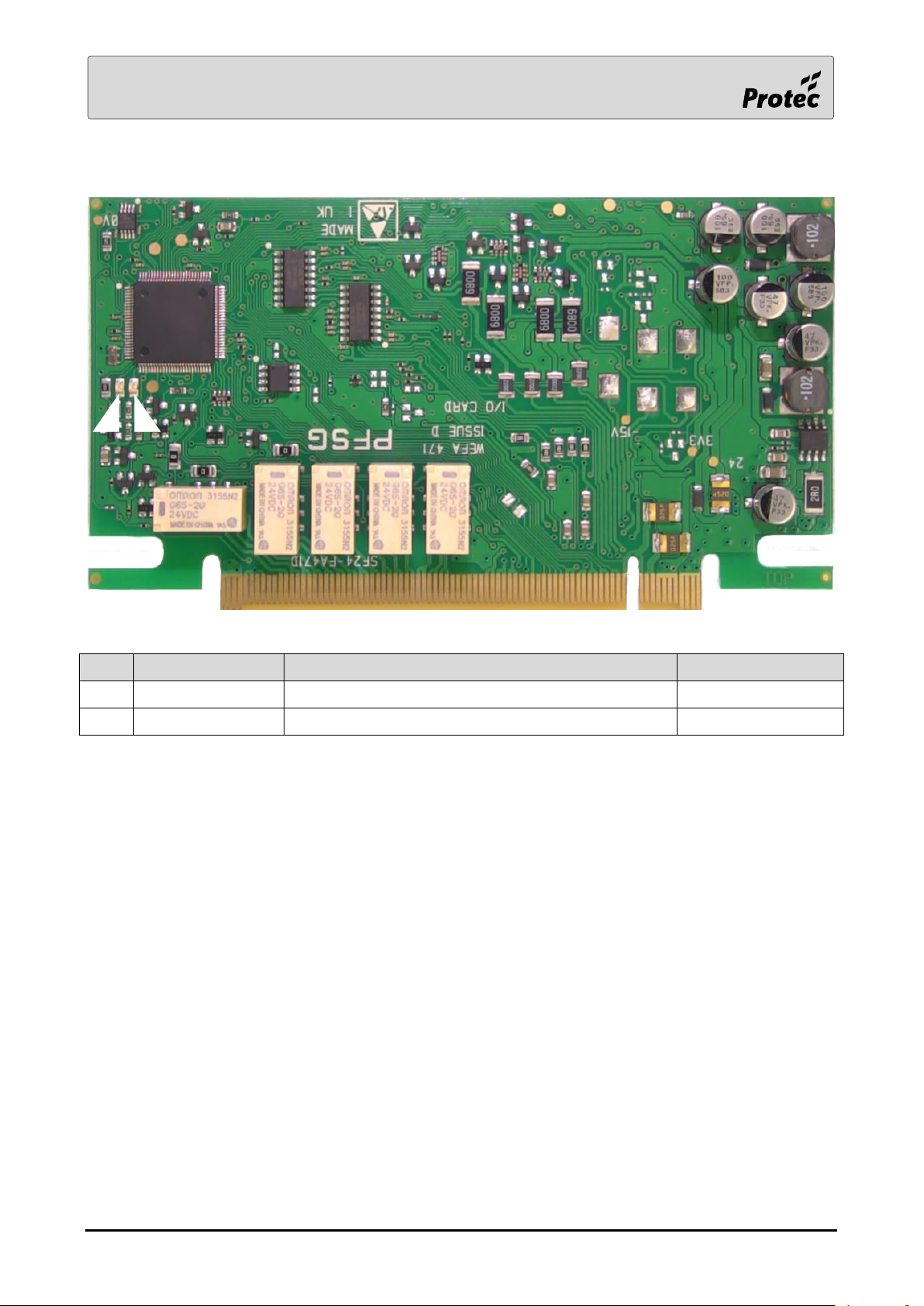
Item
Function
Description
Normal Operation
1
Run LED
Indication to show the card is communicating
Flashing Green
2
Power LED
Indication to show the card is powered
Solid Red
1
2
3.3 I/O Card
RDM0002/3 Page 50 of 57 © 2015 - 2019 Protec Fire Detection plc
Page 51
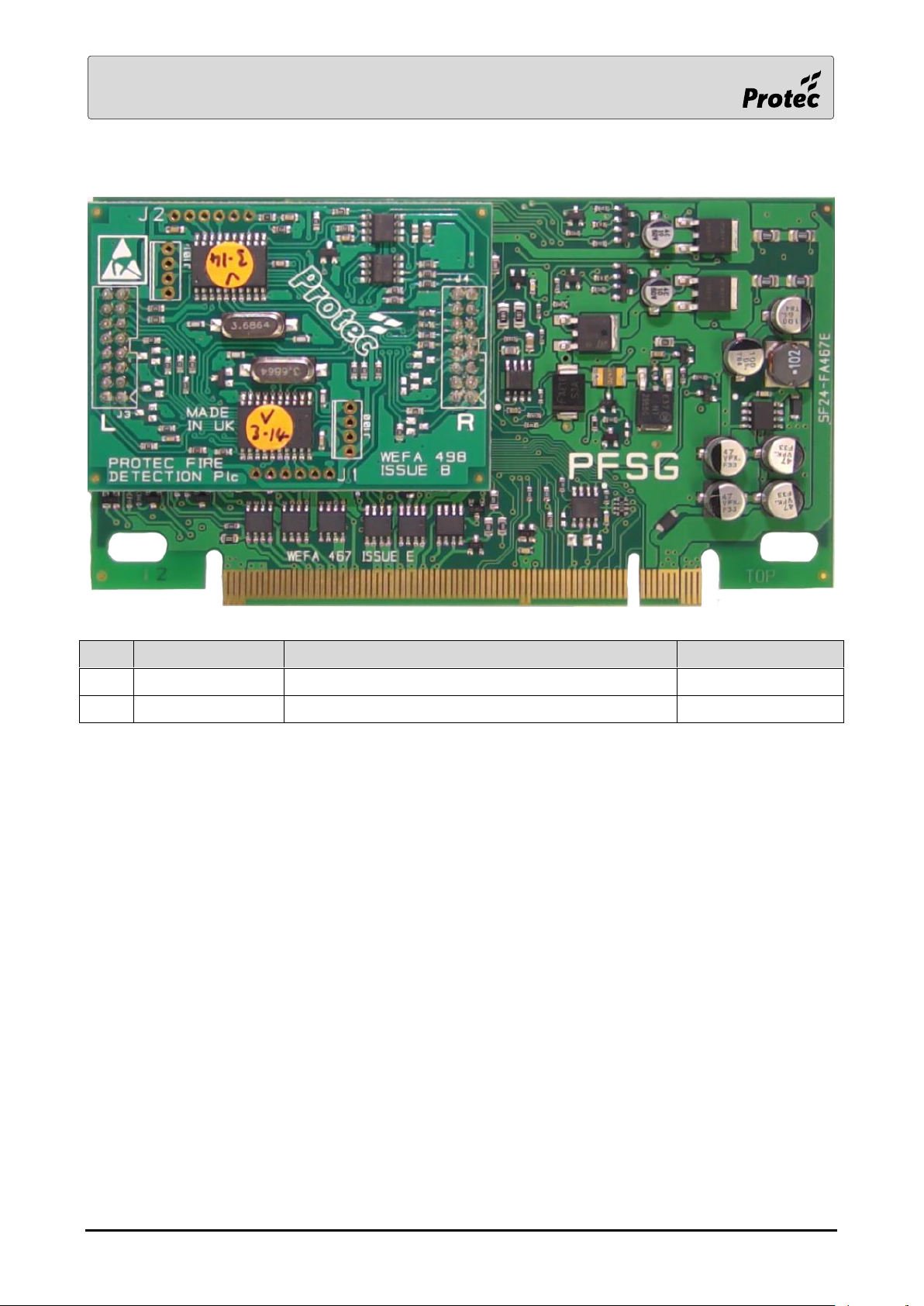
Item
Function
Description
Normal Operation
Run LED
Indication to show the card is communicating
Flashing Green
Power LED
Indication to show the card is powered
Solid Red
3.4 Loop Card
The LEDs are partially obscured by the daughter board. The operation of the LEDs can be checked by
viewing the card from the top-edge.
RDM0002/3 Page 51 of 57 © 2015 - 2019 Protec Fire Detection plc
Page 52
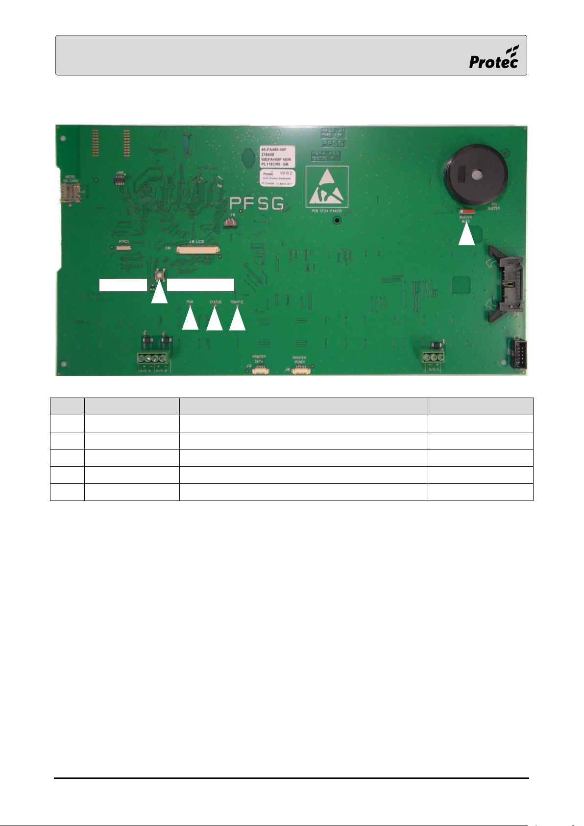
Item
Function
Description
Normal Operation
1
SW1
See Section 4.0
N/A
2
PGM
PGM
Off
3
Status
Status
Solid Red
4
Traffic
Indication to show the card is communicating
Flashing Red
5
Mute Buzzer
Slide left to mute buzzer
As shown
2
3
4 1 5
3.5 Display Card
RDM0002/3 Page 52 of 57 © 2015 - 2019 Protec Fire Detection plc
Page 53
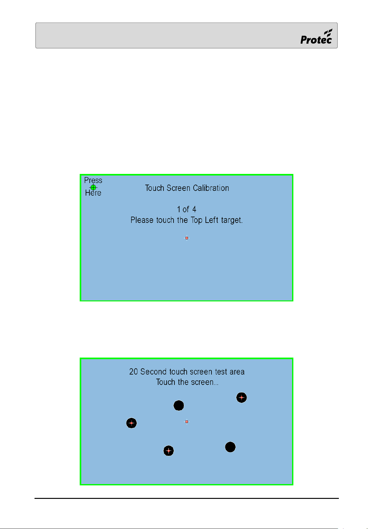
4.0 Touch screen Calibration
Note: - Capacitive touchscreens do not need to be calibrated
The resistive touchscreen will have been calibrated when the panel was tested after manufacture. If
the calibration has drifted and the touchscreen needs to be recalibrated then open the panel door and
locate SW1. Press and hold switch SW1 until the calibration screen is displayed; this will take
approximately 12 seconds.
The location of SW1 is shown in section 3.5.
The touchscreen calibration screen is shown below:-
Touch the target in the top left hand corner and the display will move the target to the bottom right
hand corner. Touch that target and it will move again until all four corners have been done. Finally a
test screen is displayed for 20 seconds so that the calibration can be tested.
Touch the screen and check that a marker appears where you have touched.
RDM0002/3 Page 53 of 57 © 2015 - 2019 Protec Fire Detection plc
Page 54
Standards
EN54 part 2 : 1997+A1:2006 , EN54 part 4 : 1997, A1:2002 + A2:2006
Approvals
LPCB CPR : 0832-CPR-F0179 Certificates : 201ag
Models
6501
6502
6504
Number of digital addressable loops
1 2 4
Standby current
150mA
150mA
180mA
Loop output current per loop
1A average, 2A peak, per loop
Max number of addressable devices
per loop
200
Display
Full colour, 7” touch screen graphical display
Zonal LED Indication
40/100 as standard, can be expanded to a maximum of 10,000
Number of conventional Alarm Circuits
3 - monitored for open and short circuits
Alarm Load
Maximum 1A per alarm circuit
Number of Key-switch Inputs
6
Auxiliary 24V Output
150mA maximum (monitored).
Auxiliary Fire Outputs
2 - Volt free changeover contacts rated at a maximum of 1A 24V dc
Auxiliary Fault Outputs
1 - Volt free changeover contacts rated at a maximum of 1A 24V dc
Fire Routing Equipment
1 - monitored for open and short circuit faults
Fire Protection Equipment Output
11
Fault routing equipment output
11
Class Change Facility
Yes, fully programmable
Communication Ports
RS232, USB (slave)
System Networking (optional)
Up to 64 panels can be connected on a fully redundant network,
monitored for open and short circuit. Maximum of 1km distance
between panels.
Standby Duration
Dependant on loop loading and battery configuration
Optional Integral Charger / Batteries
24 Vdc 3A Switch mode, 2 x 12V,12Ah
Mains input voltage for integral
230V ac +10%/ -15% 50Hz-60Hz
Optional Integral Printer
40 characters per line low noise compact thermal printer
Ambient Temperature Range
-10°C to +55°C
Humidity Limit
5 % to 95% RH ( no condensation, or icing )
IP Rating (Ingress Protection)
IP30
Dimensions
440mm (W) x 385mm (H) x 144mm (D)
Construction
Back Box- Mild steel , front door - PC/ABS to BSEN60950
Colour
Storm grey
Mounting position
Wall mounted
Mounting method
3 points surface mount or flush ( bezel required when flush mounting )
Weight (excluding batteries &
8kg
Weight (including 2 x 12V,12Ah
16kg
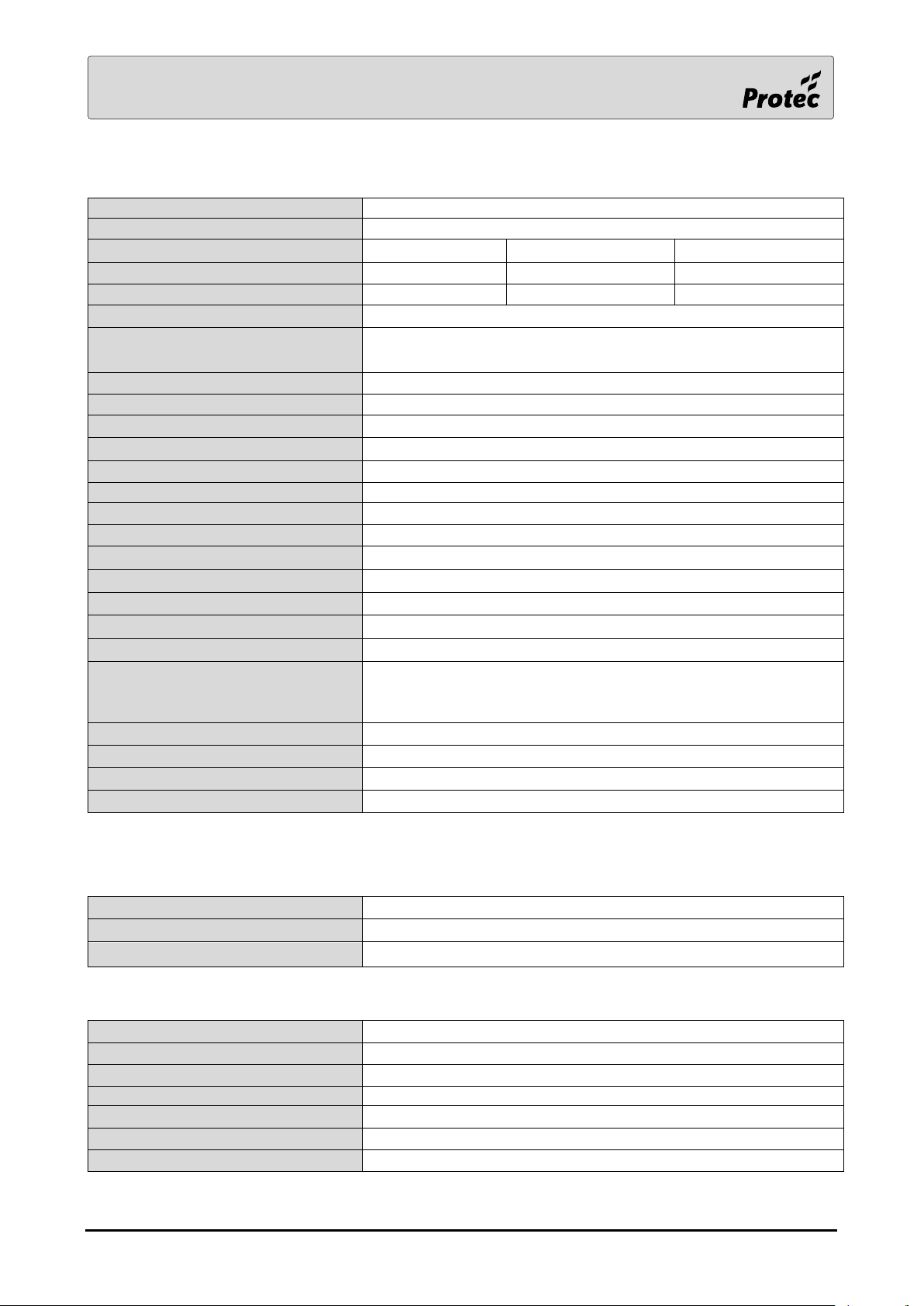
5.0 6500 Technical specification
1
If this output function is performed on the terminal board then it replaces one of the conventional alarm circuits
Environment specification
Mechanical specification
RDM0002/3 Page 54 of 57 © 2015 - 2019 Protec Fire Detection plc
Page 55
Standards
EN54 part 2 : 1997+A1:2006 , EN54 part 4 : 1997, A1:2002 + A2:2006
Approvals
LPCB CPR : 0832-CPR-F0179 Certificates : 201ag
Models
6601
6602
6604
Number of digital addressable loops
1 2 4
Standby current
150mA
150mA
180mA
Loop output current per loop
1A average, 2A peak, per loop
Max number of addressable devices per
loop
200
Display
Full colour, 7” touch screen graphical display
Zonal LED Indication
100 as standard, can be expanded as required to a maximum of 10,000
Number of conventional Alarm circuits
3 - monitored for open and short circuits
Alarm Load
Maximum 1A per alarm circuit
Clean contact outputs
3 - Volt free changeover contacts rated at a maximum of 1A 24V dc
Number of Key-switch Inputs
5
Auxiliary 24V Output
2 x 150mA maximum (monitored)
Auxiliary Fire Outputs
2 - Volt free changeover contacts rated at a maximum of 1A 24V dc
Auxiliary Fault Outputs
1 - Volt free changeover contacts rated at a maximum of 1A 24V dc
Fire Routing Equipment
3 - monitored for open and short circuit faults
Fire Protection Equipment Output
11
Fault routing equipment output
1 - monitored for open and short circuit fault
Class Change Facility
Yes, fully programmable
Communication Ports
RS232, USB (slave)
System Networking (optional)
Up to 160 panels can be connected on a fully redundant network,
monitored for open and short circuit. A maximum of 64 panels per
local network with up to 5 local networks connected via a core
network. Maximum of 1km distance between panels.
Standby Duration
Dependant on loop loading and battery configuration
Optional Integral Charger / Batteries
24 Vdc 8A Switch mode, 2 x 12V,18Ah
Mains input voltage for integral charger
230V ac +10%/ -15% 50Hz-60Hz
Optional Integral Printer
40 characters per line low noise compact thermal printer
Ambient Temperature Range
-10°C to +55°C
Humidity Limit
5 % to 95% RH ( no condensation, or icing )
IP Rating (Ingress Protection)
IP30
Dimensions
440mm (W) x 385mm (H) x 144mm (D), 580mm (H) for internal charger / batteries
Construction
Back Box- Mild steel , front door - PC/ABS to BSEN60950
Colour
Storm grey
Mounting position
Wall mounted
Mounting method
3 points surface mount or flush ( bezel required when flush mounting )
Weight (excluding batteries
10.5kg (internal charger)
Weight (including 2 x
21kg (internal charger)
6.0 6600 Technical specification
1
If this output function is performed on the terminal board then it replaces one of the conventional alarm circuits
Environment specification
Mechanical specification
RDM0002/3 Page 55 of 57 © 2015 - 2019 Protec Fire Detection plc
Page 56
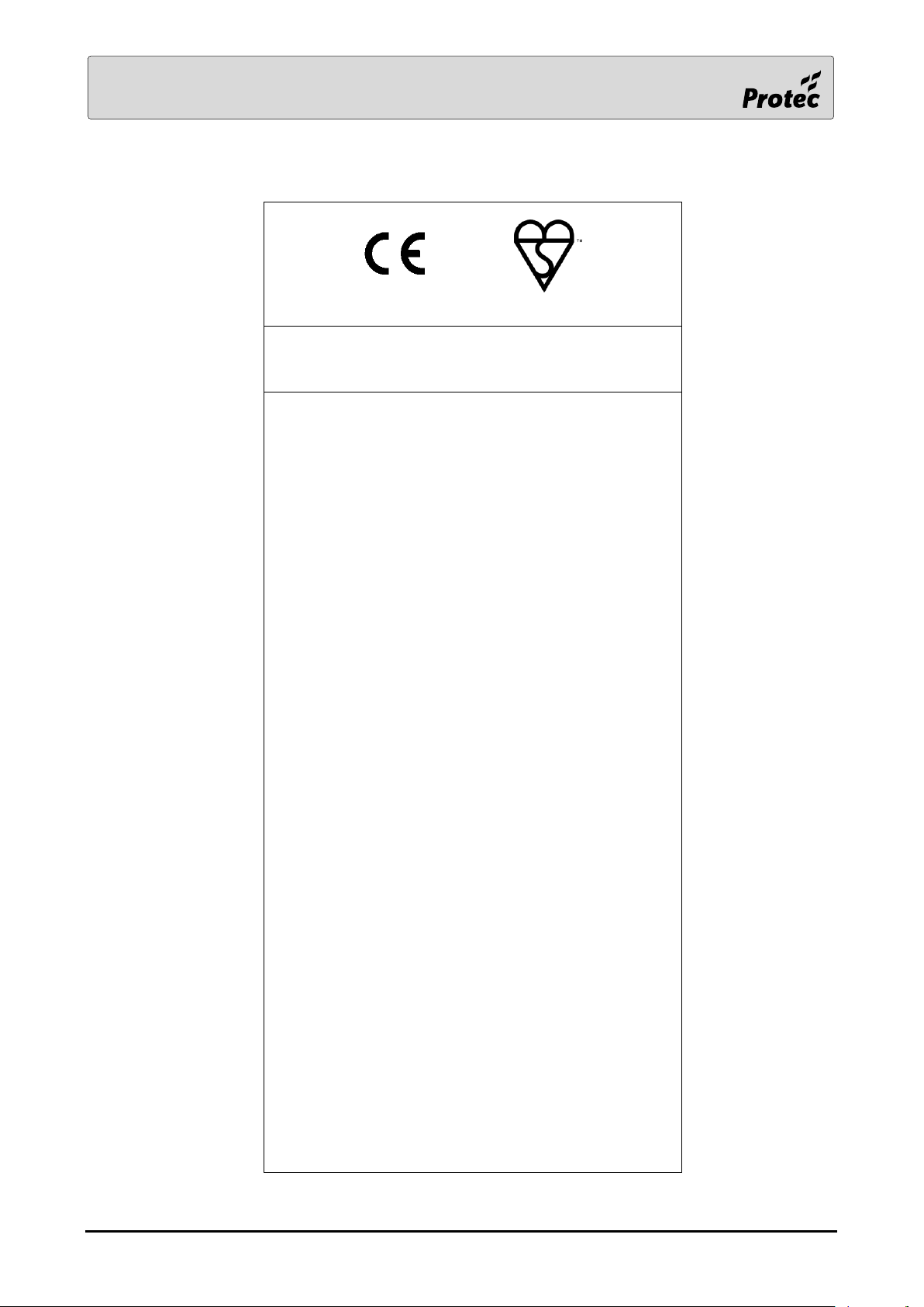
0086-CPR-575026 KM 575025
Protec Fire Detection plc, Nelson, Lancashire, England BB9 6RT
PFD-CPR-0138
This equipment has been manufactured in conformance with the
requirements of all applicable EU council directives and regulations.
BS EN 54-2:1997 + A1:2006
BS EN 54-4:1997 + A1:2002 + A2:2006
Control / Indicating and Power Supply equipment for fire detection
and fire alarm systems for buildings
6500/6600 Fire Alarm Control Panel
Options Provided
7.8 Output to fire alarm devices
7.9.1 Output to fire alarm routing equipment
7.9.2 Alarm confirmation input from fire alarm routing equipment
7.10.1 Output to automatic fire protection equipment (type A)
7.10.2 Output to automatic fire protection equipment (type B)
7.10.3 Output to automatic fire protection equipment (type C)
7.10.4 Fault monitoring of fire protection equipment (type B)
7.11 Delays to outputs
7.12.1 Dependencies on more than one alarm signal(Type A)
7.12.2 Dependencies on more than one alarm signal(Type B)
7.12.3 Dependencies on more than one alarm signal(Type C)
7.13 Alarm counter
8.9 Output to fault routing equipment
9.5 Disablement of each point
10 Test condition
Control & Indicating:
Performance under fire conditions: Pass
Response delay (response time to fire): Pass
Operational reliability: Pass
Durability of operational reliability, Temperature resistance: Pass
Durability of operational reliability, Vibration resistance: Pass
Durability of operational reliability, Electrical stability: Pass
Durability of operational reliability, Humidity resistance: Pass
Power supply:
Performance of power supply: Pass
Durability of operational reliability, Temperature resistance: Pass
Durability of operational reliability, Vibration resistance: Pass
Durability of operational reliability, Electrical stability: Pass
Durability of operational reliability, Humidity resistance: Pass
7.0 Standards, directives and regulations information
RDM0002/3 Page 56 of 57 © 2015 - 2019 Protec Fire Detection plc
Page 57

Designed and manufactured in the United Kingdom
The policy of Protec Fire Detection plc is one of continuous improvement. As such we reserve the right
to make changes to product specifications at any time and without prior notice. Errors and omissions
excepted.
Electrical or electronic devices that are no longer serviceable must be collected separately
and sent for environmentally compatible recycling (in accordance with the European
Waste Electrical and Electronic Equipment Directive). To dispose of old electrical or
electronic devices, you should use the return and collection systems put in place in the
country concerned.
This equipment has been manufactured in conformance with the requirements of all applicable EU
council directives and regulations
RDM0002/3 Page 57 of 57 © 2015 - 2019 Protec Fire Detection plc
 Loading...