

Page 1
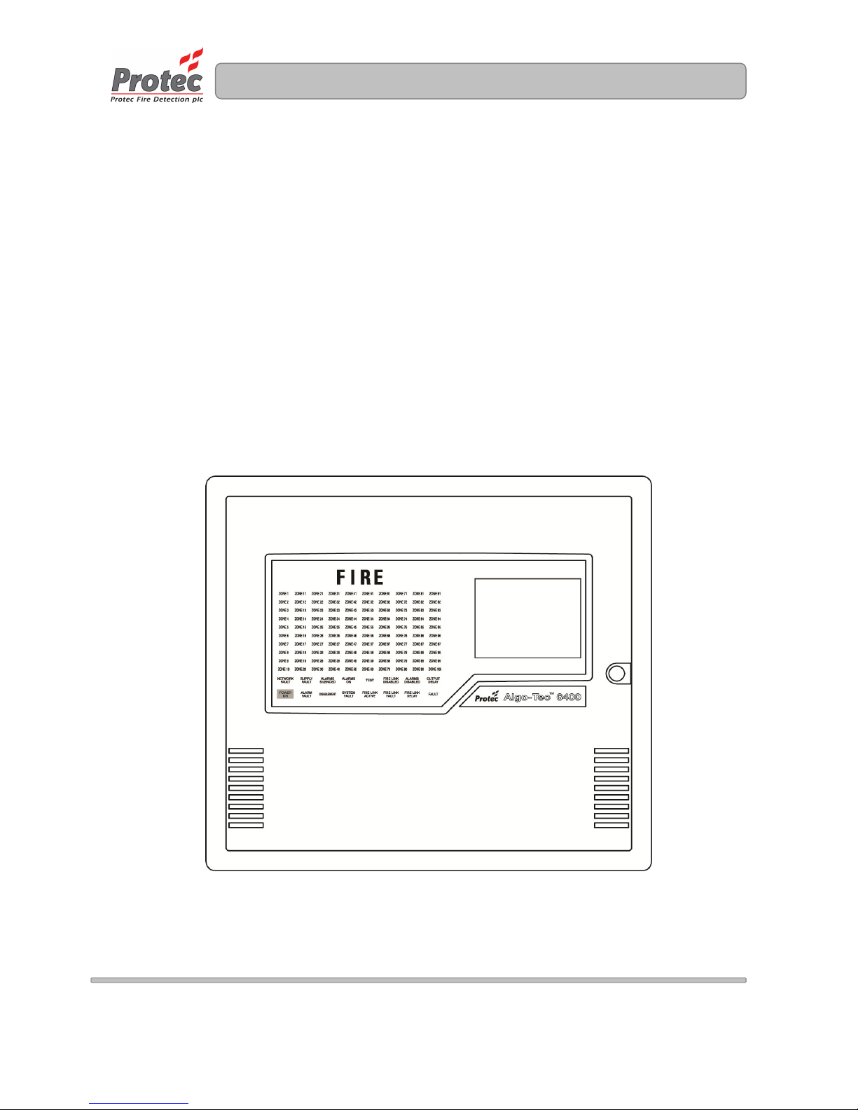
Al
go-Tec™ 6400
INTERACTIVE DIGITAL
ADDRESSABLE FIRE CONTROL
SYSTEM (1-4 LOOPS)
INSTALLATION MANUAL
www.acornfiresecurity.com
www.acornfiresecurity.com
Page 2

6400 Installation Manual - Issue 4 Rev 5 Page 2 of 33 Copyright Protec Fire Detection plc
6400 INSTALLATI
ON MANUAL
IIS
S
S
S
U
U
E
E
S
S
ISSUE DATE DETAILS OF CHANGE
CHANGED
BY
1 16/02/00 ORIGINAL ISSUE 2 16/01/01 TABLES 2 & 3 UPDATED, ADDED TABLE 4 PWD
3 12/09/01 ADDITIONAL INFORMATION PWD
4 29/11/02 TABLES 2, 3 & 4 UPDATED & PIDs ADDED PWD
4 Rev 1 16/08/05 Updated 6400 Specification PWD
4 Rev 2 05/04/06 Added 4000 & 5000 Device Information PWD
4 Rev 3 26/02/07
Amended section 3.1 - cable type & earthing
Split table 2 into tables 2a and 2b
Added 6000/CPRO to table 2b
Added 6000/DIU to table 3
Amended section 7.5 – Fault Output
Amended 6400 Specification – Aux Fault Output
Amended Appendix A – Total loss of PSU
PWD
4 Rev 4 14/05/10
Updated Appendix A
Added info on 6000Plus devices in table 2
Removed PIDs for loop devices
PWD
4 Rev 5 04/08/11
Added CE marking information in Appendix E
Added note on 4400 devices in Appendix C
Amended section 7.4 – Fire Station Output
RML
4 Rev 6 08/02/12 Amended section 2.2.1 – ‘6000 Series’ Double Addressing PWD
Notes
1) This manual covers 4400, 5400 and 6400 fire alarm systems. The differences are described in the
appropriate sections.
2) This manual also covers General Alarm and Cell Call systems.
www.acornfiresecurity.com
www.acornfiresecurity.com
Page 3

6400 Installation Manual - Issue 4 Rev 5 Page 3 of 33 Copyright Protec Fire Detection plc
6400 INSTALLATI
ON MANUAL
C
C
O
O
N
N
T
T
E
E
N
N
T
T
S
S
OOVVEERRVVIIEEWW ................................................................................................................................................................................................................................................................................................................ 55
1.1 6400 NETWORK OVERVIEW ............................................................................................................................... 5
IINNTTRROODDUUCCTTIIOONN ................................................................................................................................................................................................................................................................................................ 66
2.1 RS485 NETWORK ................................................................................................................................................... 6
2.2 ‘6000 SERIES’ LOOP ............................................................................................................................................... 6
2.2.1 ‘6000 SERIES‘ DOUBLE ADDRESSING .......................................................................................................... 7
2.3 ‘5000 SERIES’ LOOP ............................................................................................................................................... 7
2.4 ‘4000 SERIES’ LOOP ............................................................................................................................................... 7
2.5 LOOP SHORT CIRCUIT OR LOOP INTERRUPTION .......................................................................................... 7
2.6 DELAYS TO OUTPUTS .......................................................................................................................................... 8
2.7 PRISON CELL CALL SYSTEMS ............................................................................................................................ 8
CCAABBLLIINNGG .....................................................................................................................
................................................................................................................................................................................................... 99
3.1 POWER SUPPLY CABLING .................................................................................................................................. 9
3.2 SERIAL COMMUNICATIONS CABLING (RS485) ............................................................................................ 10
3.3 LOOP CABLING.................................................................................................................................................... 10
3.3.1 GUIDE TO LOOP CABLE CONDUCTOR SIZES (mm2) ............................................................................... 11
3.4 ALARM CABLING ................................................................................................................................................ 12
TABLE 1 - CABLING, NUMBER OF CORES ............................................................................................................ 12
CCUURRRREENNTT CCOONNSSUUMMPPTTIIOONN ........................................................................................................................................................................................................................................................ 1133
4.0 PANEL CURRENT ................................................................................................................................................ 13
4.1 LOOP CURRENT ( 6000 SERIES DEVICES ) ........................................................................................................... 13
4.2 LOOP CURRENT ( 5000 SERIES DEVICES ) ........................................................................................................... 13
4.3 LOOP CURRENT ( 4000 SERIES DEVICES ) ........................................................................................................... 13
TABLE 2A – ADDRESSABLE ‘6000’ LOOP EQUIPMENT CURRENT DETAILS ................................................. 14
TABLE 2B – ADDRESSABLE ‘6000’ LOOP EQUIPMENT CURRENT DETAILS CONTINUED .............................. 15
TABLE 2C – ADDRESSABLE ‘6000’ LOOP EQUIPMENT CURRENT DETAILS CONTINUED .............................. 16
TABLE 3 – ADDRESSABLE ‘6000’ LOOP EQUIPMENT WITH AUXILIARY SUPPLY ....................................... 17
CURRENT DETAILS .................................................................................................................................................. 17
TABLE 4 – NON-ADDRESSABLE ‘6000’ LOOP EQUIPMENT CURRENT DETAILS .......................................... 18
IINNSSTTAALLLLAATTIIOONN PPRROOCCEEDDUURREE ................................................................................................................................................................................................................................................ 1199
5
.1 6400 / 8A CHARGER ............................................................................................................................................. 19
5.2 6400 PANEL (DCN/2LPN OR DCN/4LPN) ........................................................................................................... 20
5.3 6400 LPN PANEL................................................................................................................................................... 21
5.4 6400 DCN PANEL .................................................................................................................................................. 22
5.5 6400 RDN PANEL .................................................................................................................................................. 23
5.6 6400 NETWORK LCD ........................................................................................................................................... 24
5.7 FIELD EQUIPMENT ............................................................................................................................................. 24
CCAABBLLEE TTEESSTT ........................................................................................................................................................................................................................................................................................................ 2255
CCOONNNNEECCTTIIOONN .................................................................................................................................................................................................................................................................................................... 2266
7.1 CONTROL EQUIPMENT ...................................................................................................................................... 26
7.2 FIELD EQUIPMENT ............................................................................................................................................. 26
7.3 ALARM CIRCUITS ............................................................................................................................................... 26
7.4 FIRE STATION OUTPUT...................................................................................................................................... 26
7.5 FAULT OUTPUT ................................................................................................................................................... 26
CCOOMMMMIISSSSIIOONNIINNGG RREEQQUUIIRREEMMEENNTTSS ...........................................................................................................
................................................................................................................. 2277
www.acornfiresecurity.com
www.acornfiresecurity.com
Page 4

6400 Installation Manual - Issue 4 Rev 5 Page 4 of 33 Copyright Protec Fire Detection plc
6400 INSTALLATI
ON MANUAL
66440000 SSPPEECCIIFFIICCAATTIIOONN .......................................................................................................................................................................................................................................................................... 2288
AAPPPPEENNDDIIXX AA ........................................................................................................................................................................................................................................................................................................ 2299
AAPPPPEENNDDIIXX BB ........................................................................................................................................................................................................................................................................................................ 3300
AAPPPPEENNDDIIXX CC ........................................................................................................................................................................................................................................................................................................ 3311
AAPPPPEENNDDIIXX DD ........................................................................................................................................................................................................................................................................................................ 3322
AAPPPPEENNDDIIXX EE ........................................................................................................................................................................................................................................................................................................ 3333
www.acornfiresecurity.com
www.acornfiresecurity.com
Page 5
6400 Installation Manual - Issue 4 Rev 5 Page 5 of 33 Copyright Protec Fire Detection plc
6400 INSTALLATI
ON MANUAL
O
O
V
V
E
E
R
R
V
VII
E
E
W
W
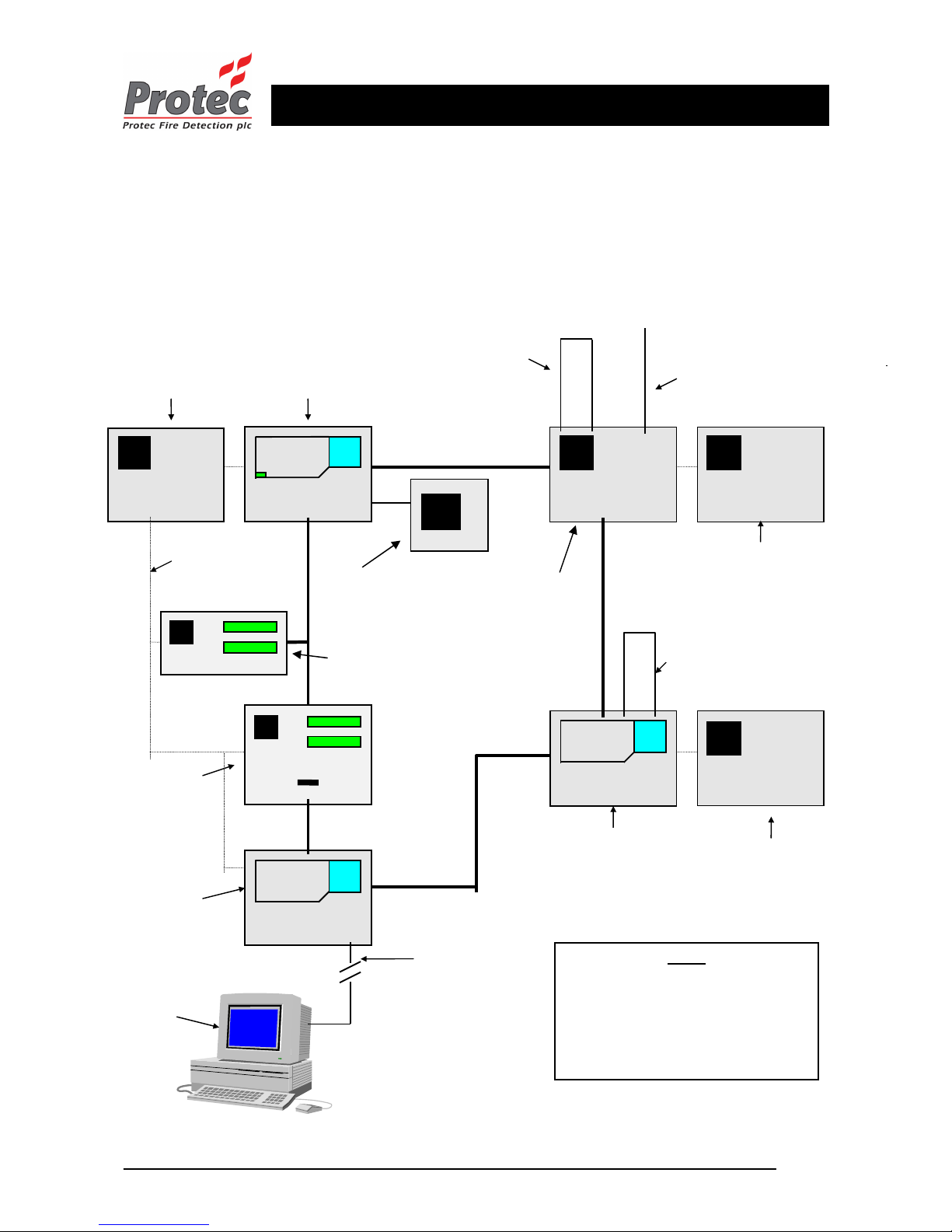
1.1 6400 NETWORK OVERVIEW
6400 PSU
To supply LPN
6400 PSU
To supply DCN
6400 DCN node
Has FULL display and control of
the network
6400 LPN
can drive up to 4 loops of
127 devices
(508 devices)
in total
6400 LPN
can drive up to
8 sounder circuits
6 aux contacts
6400 LPN node
Drives field wiring
NO control of network
KEY
LPN = Loop processing Node
DCN = Display control Node.
RDN = Repeat display Node
LCD = Liquid crystal display repeater.
PSU = Power supply unit.
6400 DCN & LPN
Drives field wiring & has FULL
control of the network
6400 LPN
can drive up to 4 loops of 127
devices (508 devices) in total, 8
sounder circuits and 6 aux contacts
6400 PSU
To supply LPN
6400 RDN Node
Has full LCD display
with (optional printer).
Limited control of the network
6400 Network LCD (Listen)
Has full LCD display. NO printer
and NO control of the network.
24 volt supply to
Network LCDs can be
taken from the node
PSU or a separate PSU
can be installed.
6400 DCN node
Has FULL display and control
of the network
2 RS232 Ports
One used to connect a PC to
program the network and one
to operate a ‘graphics’,
‘pager’ or ‘BMS’ system.
An RS232 opto-isolation unit
is fitted to provide isolation
between the 6400 panel and
other equipment.
PC or Lap-top
Can be connected to
any 6400 DCN on the
network
Zone expansion if greater
than 100 zones
www.acornfiresecurity.com
www.acornfiresecurity.com
Page 6

6400 Installation Manual - Issue 4 Rev 5 Page 6 of 33 Copyright Protec Fire Detection plc
6400 INSTALLATI
ON MANUAL
IIN
N
T
T
R
R
O
O
D
D
U
U
C
C
T
TII
O
O
N
N
This document describes the methods to be employed when installing and connecting equipment associated
with the PROTEC 6400 FIRE ALARM SYSTEM.
2.1 RS485 NETWORK
The 6400 system is a networked fire alarm system. Each 6400 unit is connected to the RS485 serial communications
network loop. A maximum of 99 nodes can be connected to the network in any combination.
With reference to the system overview in section 1 :-
6400 Unit Number of nodes
DCN 1
LPN 1
DCN/LPN 2
RDN or Mimic 1
Network LCD 0
Notes
1. The 6400/Network/LCD is connected to the RS485 network. It can receive data but not transmit data.
2. A maximum of eight 6400/Network/LCD units can be connected between any two 6400 nodes apart from a
6400/DCN/LPN panel where it is not possible to access the internal link between the two nodes.
3. Each DCN node has all of the mandatory manual controls and indicators required by En54-2
2.2 ‘6000 SERIES’ LOOP
Each 6400/LPN has the capability to communicate with Protec ‘6000 series’ loops.
Each addressable loop device has a unique Serial Number. The 6400 panel communicates with each device by this
Serial Number, and the device replies with an analogue value. This analogue value is interpreted by the panel to
determine the state of the device. The panel is therefore able to track accurately any changes in device reply values and
initiate any necessary actions.
Since each device is addressed using its serial number it is possible to have both a detection device and a sounder
assigned to the same address. This is referred to as ‘double addressing’ – see section 2.2.1.
The installer must mark up on the ‘as fit’ drawings the address of each loop device. This information will be required in
section 7.2.
www.acornfiresecurity.com
www.acornfiresecurity.com
Page 7

6400 Installation Manual - Issue 4 Rev 5 Page 7 of 33 Copyright Protec Fire Detection plc
6400 INSTALLATI
ON MANUAL
2.2.1 ‘6000 SERIES‘ DOUBLE ADDRESSING
This section applies to the original 6000 detectors and not the 6000plus detectors.
Double addressing permits a detection device and a sounder device to be assigned to the same address. This method
increases the maximum number of devices on a loop from 127. The theoretical maximum would be 254 but loop length
and loop current restrict the number.
Double addressing relies upon the sounder and detector being in the same physical location and therefore there are
limitations on which devices can be double addressed pairs.
The following sounder types will be accepted for double addressing
6000/ASB2, 6000/ASBEA2, 6000/ASB4, 6000/ASBEA4, 6000/ATSB2
These can be paired with one of the following detectors.
6000/HEAT, 6000/ION, 6000/OPT, 6000/OPHT, 6000/COHEAT, 6000/OPHTCO
2.3 ‘5000 SERIES’ LOOP
Each 5400/LPN has the capability to communicate with Protec ‘5000 series’ loops.
Each addressable loop device must have a unique address. The address is assigned using the eight way dil switch on the
device. The panel communicates with each device by this address, and the device replies with an analogue value. This
analogue value is interpreted by the panel to determine the state of the device.
The installer must mark up on the ‘as fit’ drawings the address of each loop device.
2.4 ‘4000 SERIES’ LOOP
Each 4400/LPN has the capability to communicate with Protec ‘4000 series’ loops.
Each addressable loop device must have a unique address. The address is assigned using the card inserted into the base.
The panel communicates with each device by this address, and the device replies with an analogue value. This analogue
value is interpreted by the panel to determine the state of the device.
The installer must mark up on the ‘as fit’ drawings the address of each loop device.
2.5 LOOP SHORT CIRCUIT OR LOOP INTERRUPTION
It must not be possible to have a short circuit or interruption in the loop that prevents the indication of a fire alarm from
more than one zone. To comply with this instruction, the installer must fit at least one isolator per zone. The 6000 series
loop has been designed with this in mind and so all addressable sounder bases, 6000/MICCO and 6000/MCP devices
have a built-in isolator. Check device literature for other devices with an isolator. If further isolators are required then
loop isolator bases and loop isolation units are available (see table 4).
www.acornfiresecurity.com
www.acornfiresecurity.com
Page 8

6400 Installation Manual - Issue 4 Rev 5 Page 8 of 33 Copyright Protec Fire Detection plc
6400 INSTALLATI
ON MANUAL
2.6 DELAYS TO OUTPUTS
En54-2:1997 + A1:2006 clause 7.11d states that it must be possible to override the delays and immediately action the
delayed outputs at access level one. Since access level one means that the outer panel door is locked then if delays are to
be used this clause can be met in several ways. If option (3) is chosen then this will affect the installation.
1. No delays are programmed for manual call points.
2. System programming permits a second activation to cancel delays and immediately activate outputs thus allowing
any manual call point to be pressed upon confirmation of a fire.
3. Programming at least one manual call point to activate all delayed outputs. This should be placed adjacent to each
DCN panel and its purpose clearly labelled.
2.7 P
RISON CELL CALL SYSTEMS
The 6400 is a very flexible and modular product that can be used for applications other than fire alarm systems. One
application is a prison cell call system and detailed here are additional installation requirements for such a system.
One LPN must be used to handle the cell call systems from each prison wing. The cell call system uses a Wing Office
Display Unit (WODU) that is wired on the RS485 network in the same manner as a Network LCD. Each (WODU) has
an accept button that is used to mute the buzzer on the landing indicator units. This button must be wired to a nondedicated input on the LPN that is driving the wing. If the distance between the LPN and WODU is excessive then a
relay will have to be used to switch the non-dedicated input.
All the cell call units and the corresponding landing indicator units for a single prison wing must be wired on loops
connected to the same 6400 LPN but they can be spread across all four loops. There is no restriction on the loop address
but no more than 50 devices in total can be connected on a loop due to the larger current drawn by these devices.
Contact Protec Fire Detection if it is intended to mix cell call with another discipline eg fire or pegging on the same
LPN.
www.acornfiresecurity.com
www.acornfiresecurity.com
Page 9

6400 Installation Manual - Issue 4 Rev 5 Page 9 of 33 Copyright Protec Fire Detection plc
6400 INSTALLATI
ON MANUAL
C
C
A
A
B
B
L
LII
N
N
G
G
All external wiring associated with the system must conform to the current I.E.E Regulations and cabling must conform
to the relevant BS specifications. ECA recommended Cable Separation for Electromagnetic Compatibility in Buildings,
must be followed.
All cabling must be fully phased (Identify and mark ends of cables).
Although no connections are to be made to the control panel until the commissioning stage it is important that cables
are left long enough to connect directly to the relevant terminals. To ensure that cable tails are left with sufficient length
all cable tails must be a minimum of 500mm.
3.1 POWER SUPPLY CABLING
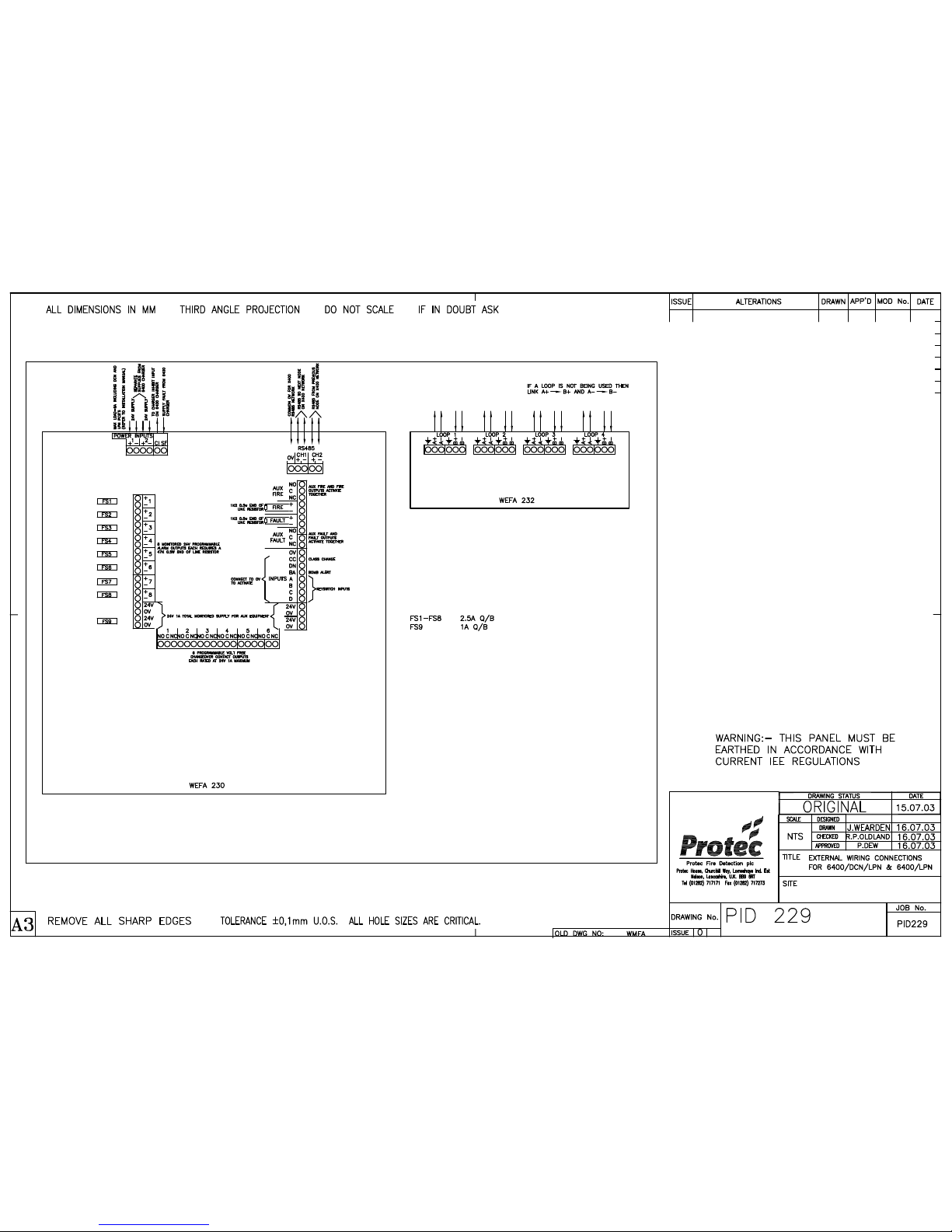
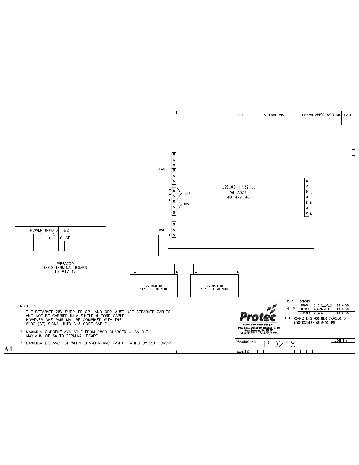
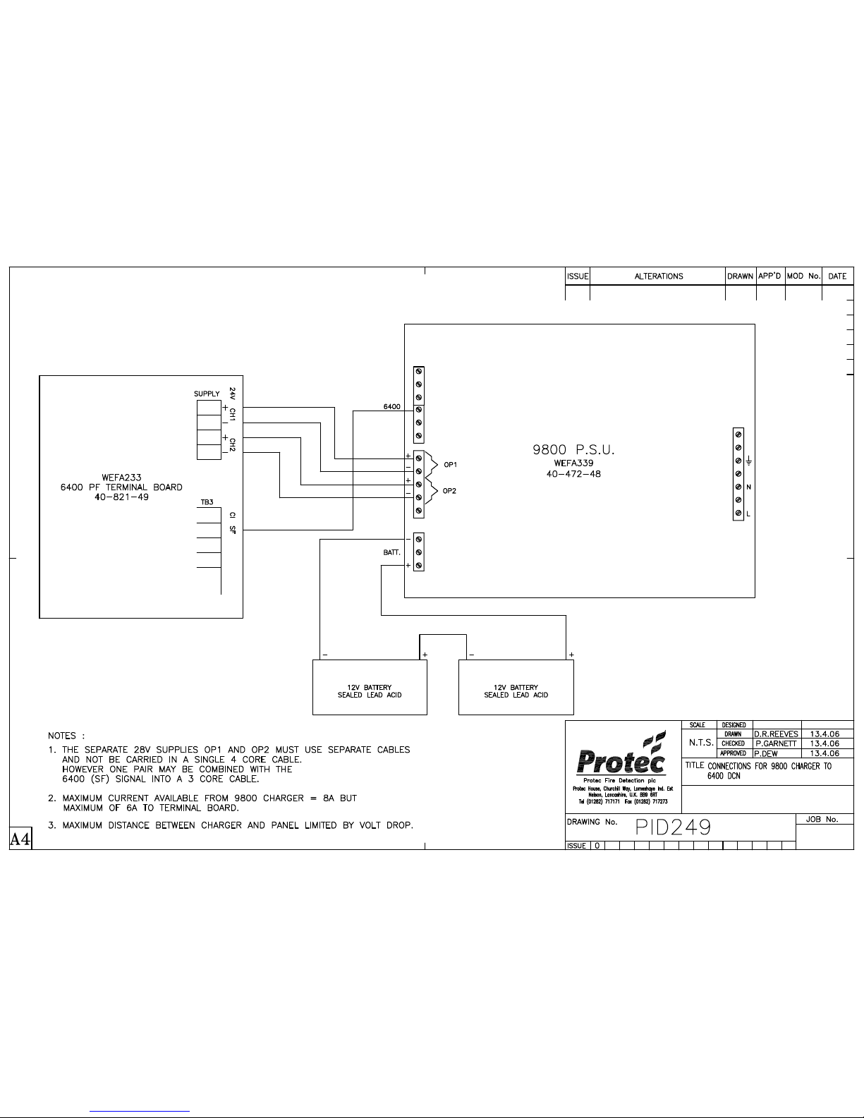
A 6400 panel requires two separate +24V supplies in order to allow the panel to continue to operate upon the loss of
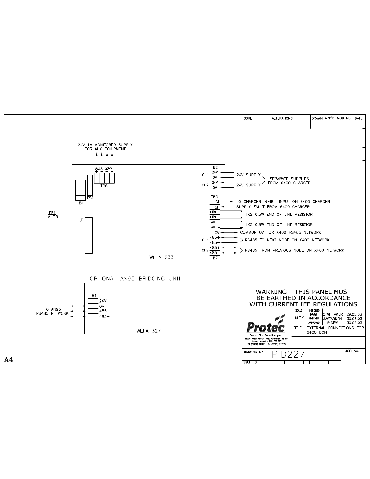
one. These two supplies must not be wired in the same fire rated cable. In addition, there is a fault signal ‘SF’ from the
charger to the panel. This signal can be combined with one of the +24V supplies into a 4-core fire rated cable (see PID
248).
The fire rated cable must be FP200 or an equivalent. The drain wire must be earthed and continuous over the complete
cable run because this connection from the charger provides the safety earth to the 6400 nodes.
The length of cable between the charger and the 6400 panel will depend upon the volt drop along the cable. No more
than 6A must be supplied to a panel and no more than two nodes must be fed from a single charger.
Note that earlier 6400 systems used a charger inhibit signal ‘CI’ from the panel to the charger. The latest 8A 6400
charger does not require this signal.
www.acornfiresecurity.com
www.acornfiresecurity.com
Page 10

6400 Installation Manual - Issue 4 Rev 5 Page 10 of 33 Copyright Protec Fire Detection plc
6400 INSTALLATI
ON MANUAL
3.2 SERIAL COMMUNICATIONS CABLING (RS485)
A 6400 panel requires two separate RS485 circuits (channel 1 and channel 2). This is because :-
1. The RS485 network is wired as a loop in order to continue to indicate a fire alarm from any device on the
system should a single break or short circuit occur in one of the RS485 circuits.
2. Interference between the RS485 channels within the same cable can cause spurious faults.
The maximum length of cable between any two nodes on the RS485 network is 1km (including any cabling for
6400/Network/LCD units) using a minimum standard of 1.5mm2 fire rated screened cable (FP200 or equivalent). The
maximum length of the RS485 loop is 5km (including all 6400/Network/LCD wiring). Should a 6400 node fail then
relays bypass the problem node isolating it from the network. The system design should ensure that under this condition
the maximum length of 1km between nodes is not exceeded.
Previously all nodes on the RS485 network had to have a common 0V reference cable. This is no longer a requirement
with most new installations since nodes now incorporate opto-isolation but allowance must be made for LCDs that do
not.
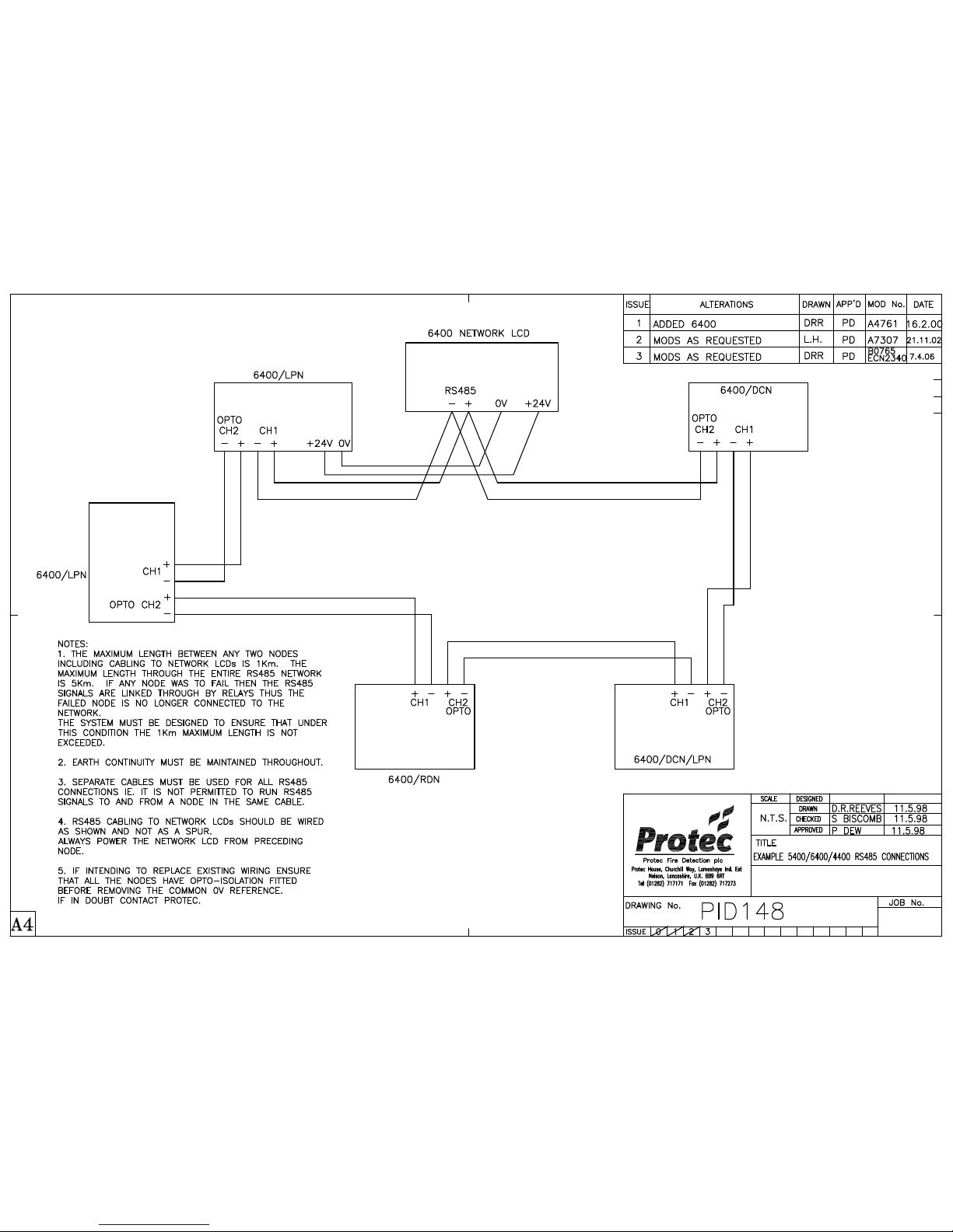
Where a 6400/Network/LCD is connected between nodes the network wiring must be taken from RS485 Channel 1of
the node previous to the LCD and then to the next node. This avoids wiring the LCD as a spur off the network. If the
distance from the node to one or more LCDs is less than 50m then a single spur from RS485 channel 1 of the node is
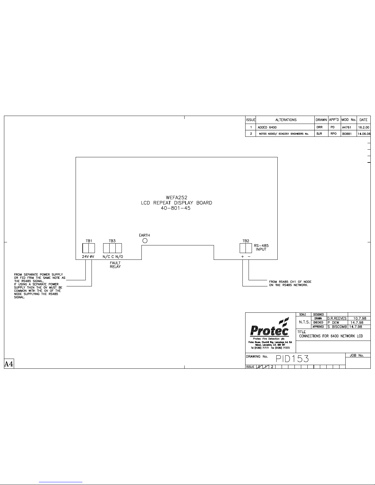
permitted. Power for the LCD can be provided locally or from the previous node but the LCD must maintain a common
0V with the previous node (see PID 148).
TO REDUCE THE RISK OF ANY STRAY ELECTRICAL SIGNALS AND TO ENSURE CORRECT
OPERATION OF THE PANEL, EACH OF THE RS485 CIRCUITS MUST BE WIRED IN A SEPARATE
SCREENED PAIR. THE SCREENS MUST BE EARTHED AND CONTINUOUS OVER THE CABLE RUN.
3.3 LOOP CABLING
The main consideration for the loop cable is the loop length. This length must include all sub-loops and spurs. For
example, a loop of 800m with three spurs of 150m must be considered as being 1250m in length.
Notes :- 1. The loop cabling must be wired in fire rated cable. The minimum conductor size is shown in the
tables of section 3.3.1. In countries where local standards permit, the loops can be wired in ‘Twin
Figure 8’ cable but the loop length and load will have to be reduced in accordance with the lower
conductor size.
2. Maximum loop resistance = 16Ω per conductor.
3. It is assumed that devices are evenly spread on the loop. If all the sounders are located at the end
of the loop then the volt drop may prevent correct operation. The ‘6000’ loop devices are rated to
operate with an input voltage range of 16 – 30V (peak).
Each address point must be numbered. Sequential address allocation of devices on the loops is not necessary with a
6400 system but it may prove advantageous for fault finding.
TO REDUCE THE RISK OF ANY STRAY ELECTRICAL SIGNALS AND TO ENSURE CORRECT
OPERATION OF THE PANEL, EACH OF THE LOOPS MUST BE WIRED IN A SEPARATE SCREENED
PAIR. THE SCREENS MUST BE EARTHED AND CONTINUOUS OVER THE CABLE RUN. THE EARTH
CONTINUITY MUST BE MAINTAINED AT ALL LOOP DEVICES.
www.acornfiresecurity.com
www.acornfiresecurity.com
Page 11

6400 Installation Manual - Issue 4 Rev 5 Page 11 of 33 Copyright Protec Fire Detection plc
6400 INSTALLATI
ON MANUAL
3.3.1 GUIDE TO LOOP CABLE CONDUCTOR SIZES (mm2)
Loop Length (metres)
500 550 600 650 700 750 800 850 900 950 1000
Total
Loop
Load
in
Alarm
(mA)
50 1.0 1.0 1.0 1.0 1.0 1.0 1.0 1.5 1.5 1.5 1.5
100 1.0 1.0 1.0 1.0 1.0 1.0 1.0 1.5 1.5 1.5 1.5
150 1.0 1.0 1.0 1.0 1.0 1.0 1.0 1.5 1.5 1.5 1.5
200 1.0 1.0 1.0 1.0 1.0 1.0 1.0 1.5 1.5 1.5 1.5
250 1.0 1.0 1.0 1.0 1.0 1.0 1.0 1.5 1.5 1.5 1.5
300 1.0 1.0 1.0 1.0 1.0 1.0 1.0 1.5 1.5 1.5 1.5
350 1.0 1.0 1.0 1.0 1.0 1.0 1.0 1.5 1.5 1.5 1.5
400 1.0 1.0 1.0 1.0 1.0 1.0 1.0 1.5 1.5 1.5 1.5
450 1.0 1.0 1.0 1.0 1.0 1.5 1.5 1.5 1.5 1.5 1.5
500 1.0 1.0 1.0 1.0 1.5 1.5 1.5 1.5 1.5 1.5 2.5
550 1.0 1.0 1.0 1.5 1.5 1.5 1.5 1.5 1.5 2.5 2.5
600 1.0 1.0 1.5 1.5 1.5 1.5 1.5 2.5 2.5 2.5 2.5
Loop Length (metres)
1000 1050 1100 1150 1200 1250 1300 1350 1400 1450 1500
Total
Loop
Load
in
Alarm
(mA)
50 1.5 1.5 1.5 1.5 1.5 2.5 2.5 2.5 2.5 2.5 2.5
100 1.5 1.5 1.5 1.5 1.5 2.5 2.5 2.5 2.5 2.5 2.5
150 1.5 1.5 1.5 1.5 1.5 2.5 2.5 2.5 2.5 2.5 2.5
200 1.5 1.5 1.5 1.5 1.5 2.5 2.5 2.5 2.5 2.5 2.5
250 1.5 1.5 1.5 1.5 1.5 2.5 2.5 2.5 2.5 2.5 2.5
300 1.5 1.5 1.5 1.5 1.5 2.5 2.5 2.5 2.5 2.5 2.5
350 1.5 1.5 1.5 1.5 1.5 2.5 2.5 2.5 2.5 2.5 2.5
400 1.5 1.5 1.5 1.5 1.5 2.5 2.5 2.5 2.5 2.5 2.5
450 1.5 1.5 1.5 1.5 2.5 2.5 2.5 2.5 2.5 2.5 2.5
500 2.5 2.5 2.5 2.5 2.5 2.5 2.5 2.5 2.5 2.5 N/A
550 2.5 2.5 2.5 2.5 2.5 2.5 2.5 2.5 2.5 2.5 N/A
600 2.5 2.5 2.5 2.5 2.5 2.5 2.5 2.5 N/A N/A N/A
www.acornfiresecurity.com
www.acornfiresecurity.com
Page 12

6400 Installation Manual - Issue 4 Rev 5 Page 12 of 33 Copyright Protec Fire Detection plc
6400 INSTALLATI
ON MANUAL
3.4 ALARM CABLING
The main consideration for the alarm cable is the length. This length must include all spurs. For example, an alarm
circuit of 800m with three spurs of 150m must be considered as being 1250m in length.
Notes :- 1. The alarm cabling must be wired in a minimum standard of 2.5mm2 fire rated cable.
2. If however, the total alarm cabling length is less than 1km, then the alarm circuit may be wired in a
minimum standard of 1.5mm2 fire rated cable. In countries where local standards permit, the alarm
circuit can be wired in ‘Twin Figure 8’ cable but the cable length and load will have to be reduced
in accordance with the lower conductor size.
3. The maximum permissible alarm circuit length is limited by volt drop.
TO REDUCE THE RISK OF ANY STRAY ELECTRICAL SIGNALS AND TO ENSURE CORRECT
OPERATION OF THE PANEL, EACH OF THE ALARM CIRCUITS MUST BE WIRED IN A SEPARATE
SCREENED PAIR. THE SCREENS MUST BE EARTHED AND CONTINUOUS OVER THE CABLE RUN.
TABLE 1 - CABLING, NUMBER OF CORES
CABLE Number of Cores
1. Supply 230 volts 50Hz
2. 24V Supply circuit 1
24V Supply circuit 2
SF Signal
3. RS485 channel 1
RS485 channel 2
RS485 channel 1 to 6400/Network/LCD
4. Loop Circuit
Alarm Circuit
5. Power Pair For: -
Zone/Alarm Interface Units
I/O Interface Units
3
2
2
1
2
2
41
2 (per loop)
2 (per circuit)
2
2
1
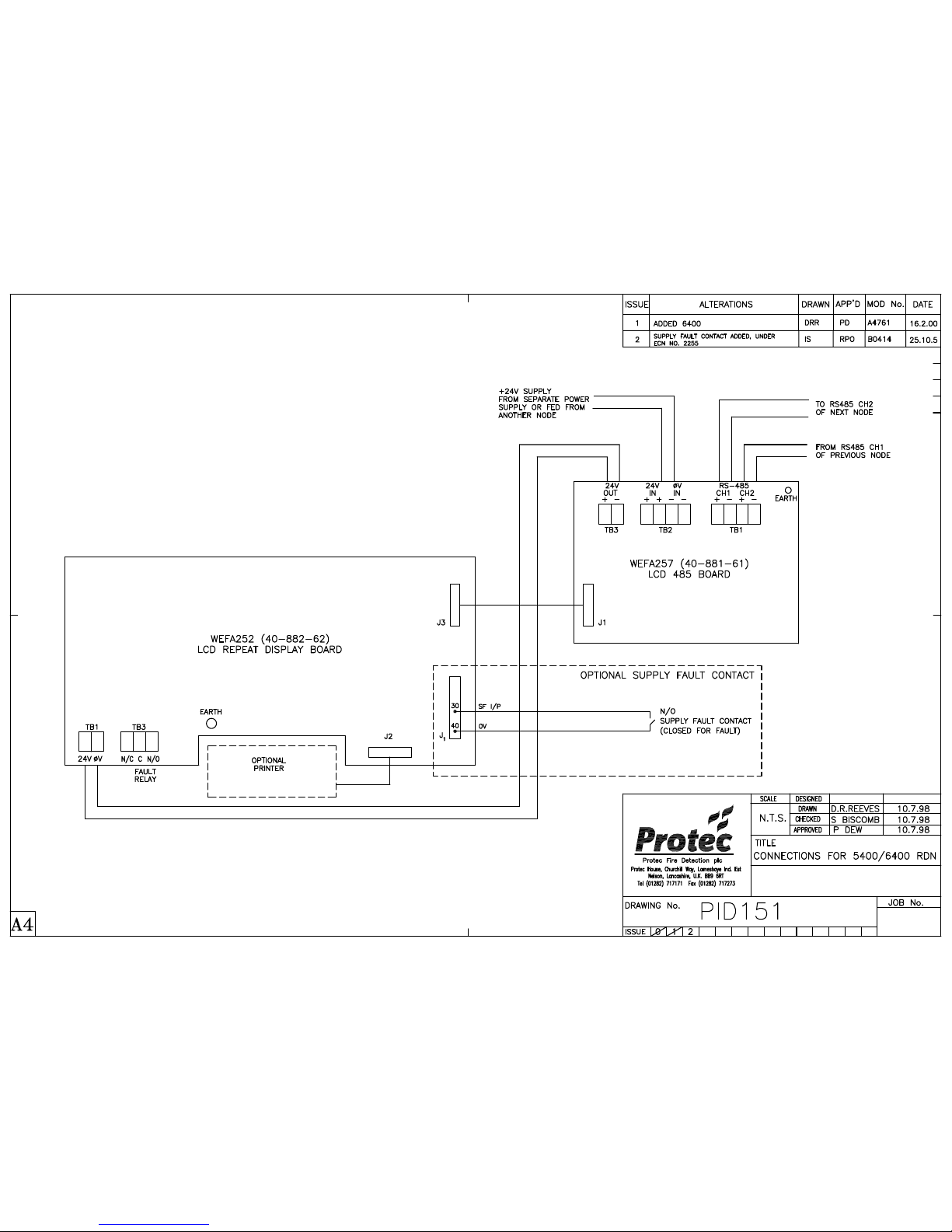
A 6400/Network/LCD requires an external +24V power supply that is usually provided by a fourth RS485 core, refer
to PID 153.
www.acornfiresecurity.com
www.acornfiresecurity.com
Page 13

6400 Installation Manual - Issue 4 Rev 5 Page 13 of 33 Copyright Protec Fire Detection plc
6400 INSTALLATI
ON MANUAL
C
C
U
U
R
R
R
R
E
E
N
N
T
T
C
C
O
O
N
N
S
S
U
U
M
M
P
P
T
TII
O
O
N
N
It is necessary to calculate current consumption figures for the system in standby (mains fail) and alarm conditions in
order to select the correct battery capacity.
4.0 PANEL CURRENT
Details of panel currents for standby and alarm are shown in the 6400 specification later in this manual.
4.1 LOOP CURRENT ( 6000 Series Devices )
Figures for the loop device current for battery capacity calculations are contained in tables 2, 3 and 4. These provide
details of the quiescent and alarm currents of both the addressable and non-addressable loop devices.
Note: -
1. Loop isolators, devices that isolate sections of the loop if short circuit wiring faults occur, are available as
separate units. Some ‘6000 series’ devices contain an isolator. Check device literature.
2. When using Zone interfaces the current per detector / sounder must be added to the current requirement of the
Interface Units (refer to note 2 of table 3).
3. The alarm loop current figures may differ from the figures quoted in other Protec literature. The figures here
assume a limit on the number of devices lighting their fire led so this reduced led current is averaged across all
the loop devices.
4.2 LOOP CURRENT ( 5000 Series Devices )
Figures for the ‘5000’ series loop device currents are provided in Appendix B.
4.3 LOOP CURRENT ( 4000 Series Devices )
Figures for the ‘4000’ series loop device currents are provided in Appendix C.
www.acornfiresecurity.com
www.acornfiresecurity.com
Page 14

6400 Installation Manual - Issue 4 Rev 5 Page 14 of 33 Copyright Protec Fire Detection plc
6400 INSTALLATI
ON MANUAL
TABLE 2a – ADDRESSABLE ‘6000’ LOOP EQUIPMENT CURRENT DETAILS
ADDRESSABLE DEVICES
QUIESCENT
LOOP CURRENT
(mA)
ALARM
LOOP CURRENT
(mA)
OPTICAL SMOKE DETECTOR
6000/OP
0.35 0.55
OPTICAL HEAT SMOKE DETECTOR
6000/OPHT
0.35 0.55
TEMPERATURE DETECTOR
6000/TEMP
0.35 0.55
OPTICAL HEAT CO SMOKE DETECTOR
6000/OP/HT/CO
0.45 0.65
CO HEAT DETECTOR
6000/HT/CO
0.35 0.55
IONISATION SMOKE DETECTOR
6000/ION
0.52 0.82
BREAK GLASS
6000/MCP
0.5 0.85
SOUNDER BASE
6000/ASB2
0.6 6
SOUNDER BASE WITH FLASHING
XENON BEACON - 6000/ASBEA2
0.6 10
RED SYMPHONY SOUNDER
6000/SYM2R
0.5 5
SOUNDER
6000/SSR2
0.65 5
SOUNDER
6000/SRZ2
0.5 20
BEACON
6000/PVR2
0.5
45 (Xenon)
5 Av / 12 pk (LED)
SOUNDER XENON BEACON
6000/SRZ2/PVR
0.5 75
MONITORED INPUT CLEAN CONTACT
OUTPUT BOARD - 6000/MICCO
1.3 5
CLEAN CONTACT OUTPUT BOARD
6000/CCO
0.6 10
MONITORED INPUT BOARD
6000/MIP
0.65 4
MONITORED INPUT WITH CLEAN
CONTACT OUTPUT - 6000/MIPCCO
0.7 15
www.acornfiresecurity.com
www.acornfiresecurity.com
Page 15

6400 Installation Manual - Issue 4 Rev 5 Page 15 of 33 Copyright Protec Fire Detection plc
6400 INSTALLATI
ON MANUAL
TABLE 2b – ADDRESSABLE ‘6000’ LOOP EQUIPMENT CURRENT DETAILS continued
ADDRESSABLE DEVICES
QUIESCENT
LOOP CURRENT
(mA)
ALARM
LOOP CURRENT
(mA)
6000Plus Optical Detector 0.2 0.55
6000Plus Heat Detector 0.2 0.55
6000Plus Optical Heat Detector 0.2 0.55
6000Plus Optical Heat Detector with Isolator 0.4 2.53
6000Plus Optical Heat Detector with Sounder 0.4 9.23
6000Plus Optical Heat Detector with Sounder
and LED Beacon
0.4 14.23
6000Plus Optical Heat Detector with Talking
Sounder
0.4 12.53
6000Plus Optical Heat Detector with Talking
Sounder and LED Beacon
0.4 17.53
6000Plus Optical Heat Detector with LED
Beacon
0.4 7.53
6000Plus Optical Heat CO Detector 0.45 0.65
6000Plus Optical Heat CO Detector with
Sounder
0.45 9.28
6000Plus Optical Heat CO Detector with
Sounder and LED Beacon
0.45 14.28
6000Plus Optical Heat CO Detector with
Talking Sounder and LED Beacon
0.45 17.58
6000Plus Optical Heat CO Detector with LED
Beacon
0.45 7.6
6000Plus Optical Detector with Sounder 0.4 9.23
6000Plus Heat Detector with LED Beacon 0.4 7.53
6000Plus Heat Detector with Sounder 0.4 9.23
6000Plus Heat Detector with Sounder and
LED Beacon
0.4 14.23
6000Plus Heat Detector with Talking Sounder
and LED Beacon
0.4 17.53
6000Plus Talking SSR 0.4 9.4
6000Plus Talking SSR with LED Beacon 0.45 14.42
www.acornfiresecurity.com
www.acornfiresecurity.com
Page 16

6400 Installation Manual - Issue 4 Rev 5 Page 16 of 33 Copyright Protec Fire Detection plc
6400 INSTALLATI
ON MANUAL
TABLE 2c – ADDRESSABLE ‘6000’ LOOP EQUIPMENT CURRENT DETAILS continued
ADDRESSABLE DEVICES
QUIESCENT
LOOP CURRENT
(mA)
ALARM
LOOP CURRENT
(mA)
LOOP BEAM DETECTOR
6000/BEAM – (MIP)
0.65 7
TALKING SOUNDER BASE
6000/ATSB2
0.7 17 (Bell tone)
6400 LOOP LCD
86 (No disablement)1
93 av. (+Disablement)
96 pk
98 (No disablement)1
101av. (+Disablement)
103pk
CIRRUS PRO INTERFACE
6000/CPRO
10 10
LOCAL CONTROL MODULE 0.7 + detectors + EOL 67mA
1
Figure assumes a supply fault, buzzer on and both LCD backlights on
www.acornfiresecurity.com
www.acornfiresecurity.com
Page 17

6400 Installation Manual - Issue 4 Rev 5 Page 17 of 33 Copyright Protec Fire Detection plc
6400 INSTALLATI
ON MANUAL
TABLE 3 – ADDRESSABLE ‘6000’ LOOP EQUIPMENT WITH AUXILIARY SUPPLY
CURRENT DETAILS
ADDRESSABLE DEVICES QUIESCENT (mA) ALARM (mA)
LOOP 24V LOOP 24V
SOUNDER BASE WITH AUXILIARY SUPPLY
(6000/ASB4)
0.58 - 1.5 8
SOUNDER BASE WITH FLASHING XENON
BEACON (AUXILIARY SUPPLY)
(6000/ASBEA4)
0.58 - 1.5
25 average
80 peak1
SOUNDER WITH AUXILIARY SUPPLY
6000/SRZ4
0.5 - 2 20
XENON BEACON WITH AUXILIARY SUPPLY
6000/PVR4
0.5 - 2 45
SOUNDER XENON BEACON WITH
AUXILIARY SUPPLY
6000/SRZ4/PVR
0.5 - 2 75
ZONE ALARM INTERFACE
6000/ZA
2 4 + zone load 4
35 + alarm load
(1A max)
16 WAY INTERFACE
6000/16WAY2
7
18 + zone load +
16 per output relay
+ output board
load (5A max)
7
18 + zone load +
16 per output relay
+ output board
load (5A max)
CELL CALL RESET UNIT
6000/CCALL
10
7 min
125 max
10
7 min
125 max
LANDING INDICATOR UNIT
6000/LIU
10
5 min
125 max
10
5 min
125 max
DAMPER INTERFACE UNIT
6000/DIU
4
450 max
4 450 max
1
The peak values occur when the beacon is at its ‘on’ stage during flashing.
2
There are variants of this product depending upon the monitoring requirements.
www.acornfiresecurity.com
www.acornfiresecurity.com
Page 18

6400 Installation Manual - Issue 4 Rev 5 Page 18 of 33 Copyright Protec Fire Detection plc
6400 INSTALLATI
ON MANUAL
TABLE 4 – NON-ADDRESSABLE ‘6000’ LOOP EQUIPMENT CURRENT DETAILS
NON-ADDRESSABLE DEVICE QUIESCENT (mA) ALARM (mA)
LOOP 24V LOOP 24V
24V SOUNDER BASE
(6000/SB)
- - - 7
24V SOUNDER BASE WITH XENON BEACON
(6000/SBEA)
- - -
25 average
80 peak1
FLUSH ISOLATOR UNIT
6000/FIU
0.12 - 0.12 -
BOXED ISOLATOR UNIT
6000/IU
0.12 - 0.12 -
DUAL ISOLATOR BASE
6000/DIB
0.12 - 0.12 -
STANDARD BASE
6000/BASE
- - - -
RELAY BASE
6000/RBNC or 6000/RBNO
0.05 - 15 -
www.acornfiresecurity.com
www.acornfiresecurity.com
Page 19

6400 Installation Manual - Issue 4 Rev 5 Page 19 of 33 Copyright Protec Fire Detection plc
6400 INSTALLATI
ON MANUAL
IIN
N
S
S
T
T
A
A
L
L
L
L
A
A
T
TII
O
O
N
N
P
P
R
R
O
O
C
C
E
E
D
D
U
U
R
R
E
E
5.1 6400 / 8A CHARGER
A 6400 8A charger is supplied complete and fully assembled in one box. The box also contains an installation template
showing mounting hole & cable entry positions with spirit level and plumb bob references.
1) Unpacking
Remove the installation template from the packaging - leaving the 6400 charger in the box for protection.
2) Preparing the Mounting Position
Select a dry, well ventilated position for the charger that is within the 6400 environmental specification. Use the
installation template together with a spirit level etc. to mark, drill and plug the three mounting holes in the desired
position. The charger must be mounted in the orientation shown on the template.
3) Removal of the Door
Remove the charger unit from the packaging. Use the key supplied to unlock the door. Disconnect the ribbon cable and
the earthing point on the door. Remove the door by extracting the two hinge pins. Place the door back in the box for
protection.
4) Removal of the battery clamp and PSU
Remove the two screws holding the battery clamp and
carefully withdraw the clamp ensuring that it cannot short out the
battery terminals (if present). Disconnect the earth connections from the PSU to the enclosure. Remove the four screws
fixing the PSU and place the PSU in the box for protection. DO NOT REMOVE THE EARTH CONNECTIONS
FROM THE EARTH STUD.
5) Preparing and fixing the charger
Use the installation template supplied to mark out suitable positions for cable entry on the back of the enclosure i.e. not
behind the PSU or batteries. Cut out the cable entry position and mount the enclosure at the position prepared in (2)
feeding cables through into the box.
6) Re-fitting the PSU and battery clamp
Re-fit the PSU (re-fit is reversal of 4). ENSURE THAT ALL THE EARTH CONNECTIONS REMOVED IN (4)
ARE RE-CONNECTED. Refit the battery clamp (re-fit is reversal of 4) ensuring that the clamp cannot touch the
battery terminals. Do not connect any other wiring to the charger.
7) Re-fitting the Door
Re-fit the inner door (re-fit is reversal of 3) ENSURE THAT ALL EARTHING POINTS ARE RE-CONNECTED.
www.acornfiresecurity.com
www.acornfiresecurity.com
Page 20

6400 Installation Manual - Issue 4 Rev 5 Page 20 of 33 Copyright Protec Fire Detection plc
6400 INSTALLATI
ON MANUAL
5.2 6400 PANEL (DCN/2LPN or DCN/4LPN)
A 6400 panel is supplied complete and fully assembled in one box. The box also contains an installation template
showing mounting hole & cable entry positions with spirit level and plumb bob references.
1) Unpacking
Remove the installation template from the packaging - leaving the 6400 unit in the box for protection.
2) Preparing the Mounting Position
Select a dry position for the panel that is within the 6400 environmental specification. Use the installation template
together with a spirit level etc. to mark, drill and plug the three mounting holes in the desired position. The panel must
be mounted in the orientation shown on the template.
3) Removal of the Outer Plastic Door
Remove the 6400 unit from the packaging. Use the key supplied to unlock the outer plastic door, remove the door by
extracting the hinge pins and place the door back in the box for protection.
4) Removal of the Inner Door
Unscrew the three fixings on the metal inner door at the lock side of the door. Open the inner door and disconnect the
earthing points on the door. Disconnect the ribbon cable that connects the main board on the door to the back of the
enclosure and the power supply connectors attached to the pcbs on the door. Close the door and extract the two
remaining hinge pins. Carefully remove the inner door from the unit including all circuit boards fitted to it and place it
back in the box for protection.
5) Removal of the Gear-tray
Remove the screw from the bottom of the gear-tray (in the back of the enclosure) and loosen the two at the top (keyhole fixings). Disconnect the earth connection from the gear-tray to the enclosure. Remove the gear-tray from the
enclosure as a single item including the attached circuit boards.
6) Preparing and fixing The Unit
Use the installation template to mark out a suitable position for cable entry on the back of the enclosure i.e. not behind
the gear-tray. Cut out the cable entry position and mount the enclosure at the position prepared in (2) feeding cables
through into the box.
7) Re-fitting the Gear-tray
Re-fit the gear tray (re-fit is reversal of 5). ENSURE THAT THE EARTH CONNECTIONS REMOVED IN (5)
ARE RE-CONNECTED. Do not connect any other wiring to the panel.
8) Re-fitting the Inner Door
Re-fit the inner door (re-fit is reversal of 4) ENSURE THAT ALL EARTHING POINTS ARE RE-CONNECTED.
9) Re-fitting the Plastic Door
Re-fit the outer plastic door by offering the door up to the hinges and inserting the two hinge pins.
www.acornfiresecurity.com
www.acornfiresecurity.com
Page 21

6400 Installation Manual - Issue 4 Rev 5 Page 21 of 33 Copyright Protec Fire Detection plc
6400 INSTALLATI
ON MANUAL
5.3 6400 LPN PANEL
A 6400 LPN is supplied complete and fully assembled in one box. The box also contains an installation template
showing mounting hole & cable entry positions with spirit level and plumb bob references.
1) Unpacking
Remove the installation template from the packaging - leaving the 6400 unit in the box for protection.
2) Preparing the Mounting Position
Select a dry position for the panel that is within the 6400 environmental specification. Use the installation template
together with a spirit level etc. to mark, drill and plug the three mounting holes in the desired position. The panel must
be mounted in the orientation shown on the template.
3) Removal of the door
Remove the 6400/LPN unit from the packaging. Use the key supplied to unlock the door. Disconnect the ribbon cable
and the power supply cable from the door. Disconnect the earthing point on the door and remove the door by extracting
the two hinge pins. Place the door back in the box for protection.
4) Removal of the Gear-tray
Remove the screw from the bottom of the gear-tray (in the back of the enclosure) and loosen the two at the top (keyhole fixings). Disconnect the earth connection from the gear-tray to the enclosure. Remove the gear-tray from the
enclosure as a single item including the attached circuit boards.
5) Preparing and fixing the Unit
Use the installation template to mark out a suitable position for cable entry on the back of the enclosure i.e. not behind
the gear-tray. Cut out the cable entry position and mount the enclosure at the position prepared in (2) feeding cables
through into the box.
6) Re-fitting the Gear-tray
Re-fit the gear tray (re-fit is reversal of 5). ENSURE THAT THE EARTH CONNECTIONS REMOVED IN (4)
ARE RE-CONNECTED. Do not connect any other wiring to the panel.
7) Re-fitting the Door
Re-fit the inner door (re-fit is reversal of 3). ENSURE THAT ALL EARTHING POINTS ARE RE-CONNECTED.
www.acornfiresecurity.com
www.acornfiresecurity.com
Page 22

6400 Installation Manual - Issue 4 Rev 5 Page 22 of 33 Copyright Protec Fire Detection plc
6400 INSTALLATI
ON MANUAL
5.4 6400 DCN PANEL
A 6400 DCN is supplied complete and fully assembled in one box. The box also contains an installation template
showing mounting hole & cable entry positions with spirit level and plumb bob references.
1) Unpacking
Remove the installation template from the packaging - leaving the 6400 unit in the box for protection.
2) Preparing the Mounting Position
Select a dry position for the panel that is within the 6400 environmental specification. Use the installation template
together with a spirit level etc. to mark, drill and plug the three mounting holes in the desired position. The panel must
be mounted in the orientation shown on the template.
3) Removal of the Outer Plastic Door
Remove the 6400/DCN unit from the packaging. Use the key supplied to unlock the outer plastic door, remove the door
by extracting the hinge pins and place the door back in the box for protection.
4) Removal of the Inner Door
Unscrew the three fixings on the metal inner door at the lock side of the door. Open the inner door and disconnect the
earthing points on the door. Disconnect the ribbon cable that connects the main board on the door to the back of the
enclosure and the power supply connectors attached to the pcbs on the door. Close the door and extract the two
remaining hinge pins. Carefully remove the inner door from the unit including all circuit boards fitted to it and place it
back in the box for protection.
5) Removal of the terminal board
Remove the screws holding the terminal board to the enclosure. Remove the terminal board and place it back in the box
for protection.
6) Preparing and fixing the DCN
Use the installation template to mark out a suitable position for cable entry on the back of the enclosure i.e. not behind
the terminal board. Cut out the cable entry position and mount the enclosure at the position prepared in (2) feeding
cables through into the box.
7) Re-fitting the terminal board
Re-fit the terminal board (re-fit is reversal of 5). Ensure that all the screws removed in (5) are re-connected. Do not
connect any other wiring to the terminal board.
8) Re-fitting the Inner Door
Re-fit the inner door (re-fit is reversal of 4) ENSURE THAT ALL EARTHING POINTS ARE RE-CONNECTED.
9) Re-fitting the Plastic Door
Re-fit the outer plastic door by offering the door up to the hinges and inserting the two hinge pins.
www.acornfiresecurity.com
www.acornfiresecurity.com
Page 23

6400 Installation Manual - Issue 4 Rev 5 Page 23 of 33 Copyright Protec Fire Detection plc
6400 INSTALLATI
ON MANUAL
5.5 6400 RDN PANEL
A 6400 RDN is supplied complete and fully assembled in one box. The box also contains an installation template
showing mounting hole & cable entry positions with spirit level and plumb bob references.
1) Unpacking
Remove the installation template from the packaging - leaving the 6400 unit in the box for protection.
2) Preparing the Mounting Position
Select a dry position for the panel that is within the 6400 environmental specification. Use the installation template
together with a spirit level etc. to mark, drill and plug the three mounting holes in the desired position. The panel must
be mounted in the orientation shown on the template.
3) Removal of the Outer Plastic Door
Remove the 6400/RDN unit from the packaging. Use the key supplied to unlock the outer plastic door, remove the door
by extracting the hinge pins and place the door back in the box for protection.
4) Removal of the Inner Door
Unscrew the three fixings on the metal inner door at the lock side of the door. Open the inner door and disconnect the
earthing points on the door. Disconnect the power supply cables from the terminal board in the box. Close the door and
extract the two remaining hinge pins. Carefully remove the inner door from the unit including the circuit board fitted to
it and place it back in the box for protection.
5) Removal of the terminal board
Remove the screws holding the terminal board to the enclosure. Remove the terminal board and place it back in the box
for protection.
6) Preparing and fixing the RDN
Use the installation template to mark out cable entry positions on the back of the enclosure. i.e. not behind the
terminal board. Cut out the cable entry positions and mount the enclosure at the position prepared in (2) feeding
cables through into the box.
7) Re-fitting the terminal board
Re-fit the terminal board (re-fit is reversal of 5). Ensure that all the screws removed in (5) are re-connected.
8) Re-fitting the Inner Door
Re-fit the inner door (re-fit is reversal of 4) ENSURE THAT ALL EARTHING POINTS ARE RE-CONNECTED.
Reconnect the power supply cables from the inner door to the terminal board that were removed in (4) but do not
connect any other cables to the terminal board.
9) Re-fitting the Plastic Door
Re-fit the outer plastic door by offering the door up to the hinges and inserting the two hinge pins.
www.acornfiresecurity.com
www.acornfiresecurity.com
Page 24

6400 Installation Manual - Issue 4 Rev 5 Page 24 of 33 Copyright Protec Fire Detection plc
6400 INSTALLATI
ON MANUAL
5.6 6400 NETWORK LCD
A 6400 Network LCD is supplied complete and fully assembled in one box.
1) Removal of the front plate
Remove the 6400/Network/LCD unit from the packaging. Use the Allen key supplied to unlock the front plate. Remove
the front plate by disconnecting the wires and extracting the hinge pins. Place the front plate with the pcb attached back
in the box for protection.
2) Preparing the Mounting Position
Select a dry position for the panel that is within the 6400 environmental specification. Use the back-box together with a
spirit level etc. to mark, drill and plug the three mounting holes in the desired position. The panel must be mounted with
the lock at the top.
3) Preparing and fixing the LCD
Remove knock-outs as required in the rear of the back-box for cable entry. Mount the back-box at the position prepared
in (2) feeding cables through into the box.
4) Re-fitting the front plate
Re-fit the front plate (re-fit is reversal of 1). Ensure that all the wires removed in (1) are re-connected. ENSURE THAT
ALL EARTHING POINTS ARE RE-CONNECTED. Do not connect any other cables to the panel.
5.7 FIELD EQUIPMENT
All metal termination boxes and detector bases should be securely fastened to the mounting surface and earth bonded.
FIELD EQUIPMENT MUST NOT BE CONNECTED AT THIS STAGE.
www.acornfiresecurity.com
www.acornfiresecurity.com
Page 25

6400 Installation Manual - Issue 4 Rev 5 Page 25 of 33 Copyright Protec Fire Detection plc
6400 INSTALLATI
ON MANUAL
C
C
A
A
B
B
L
L
E
E
T
T
E
E
S
S
T
T
Before connecting external cables to any field device, tests must be carried out using a 500V DC insulation tester
(megger). The readings between each cable core, and each core and earth must be greater than 10M ohms (record the
readings). Equipment connected to the cabling during insulation tests could be damaged with the high voltages
produced. Great care must be taken during insulation tests to discharge the cables, since charged cable may damage the
control equipment upon connection.
www.acornfiresecurity.com
www.acornfiresecurity.com
Page 26

6400 Installation Manual - Issue 4 Rev 5 Page 26 of 33 Copyright Protec Fire Detection plc
6400 INSTALLATI
ON MANUAL
C
C
O
O
N
N
N
N
E
E
C
C
T
TII
O
O
N
N
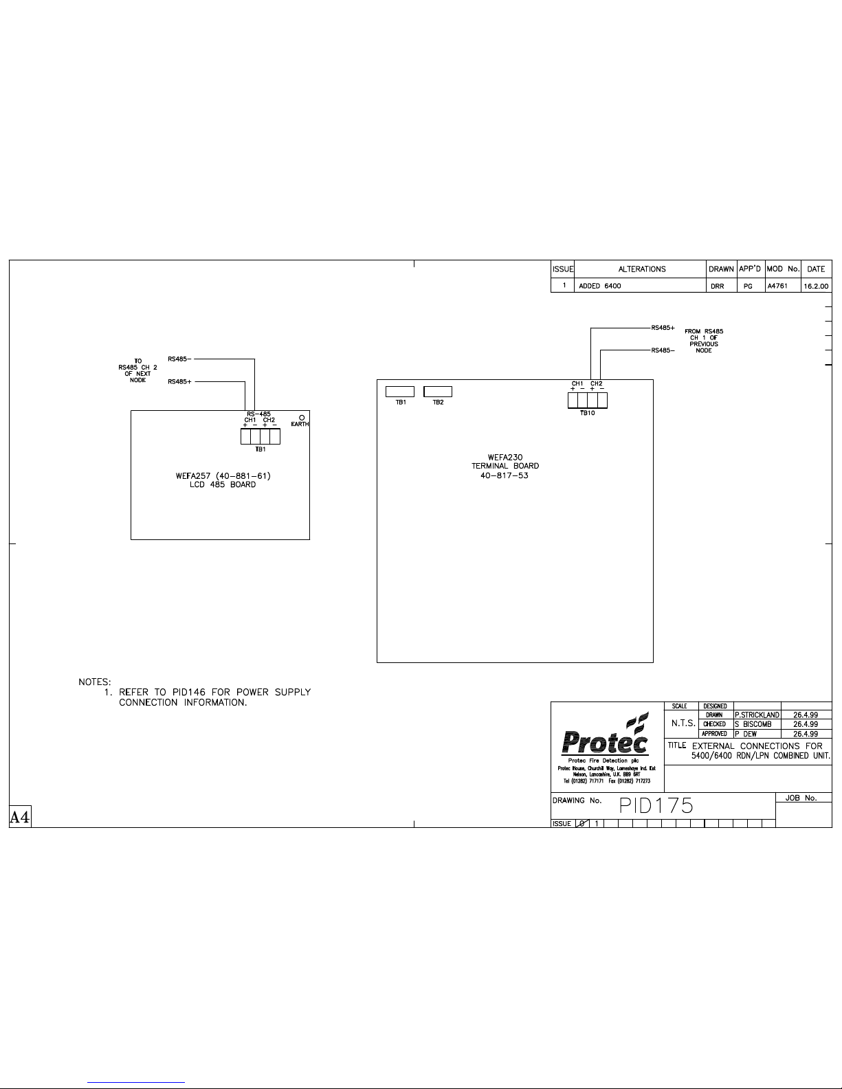
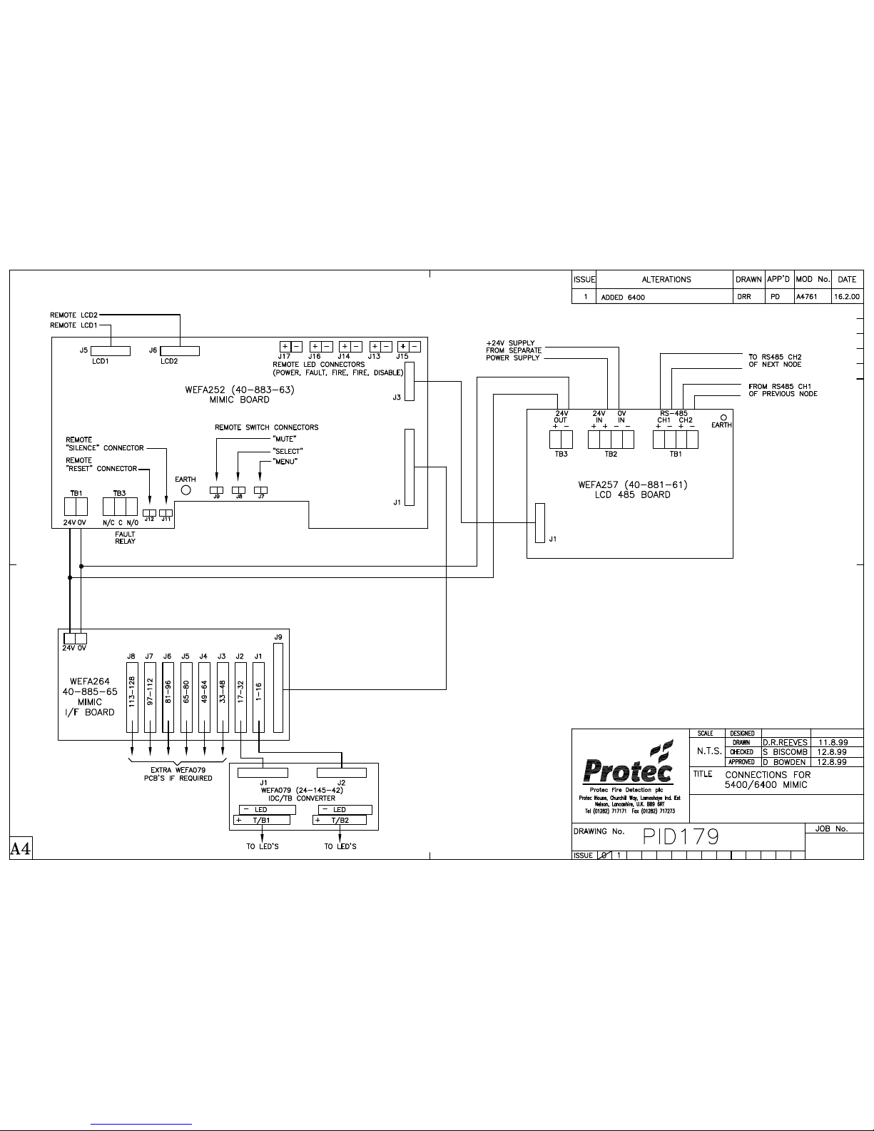
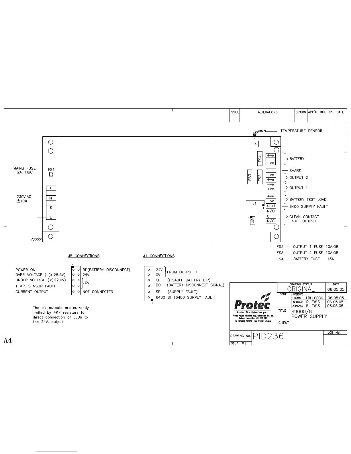
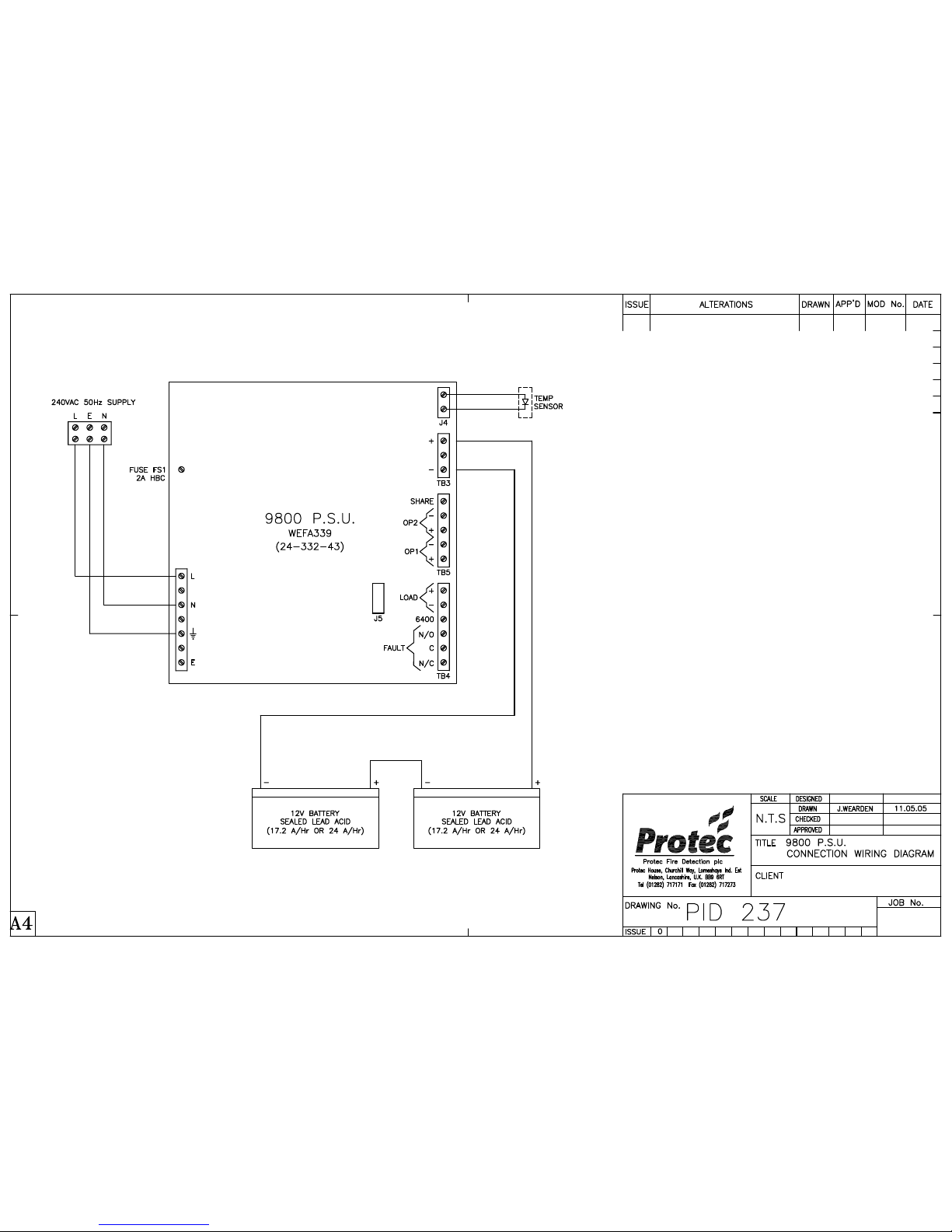
For general wiring details see the Product Information Drawings in appendix D.
7.1 CONTROL EQUIPMENT
Wiring details are supplied for reference only.
Do not make any connections to the control panel
7.2 FIELD EQUIPMENT
In order to perform the commissioning of devices correctly, the following procedure needs to be carried out upon
installation of each ‘6000 Series’ addressable loop device: -
• Remove one of the unique Serial Number bar code labels.
• Place this label at the chosen Loop and Address position in the ‘6400 Commissioning Booklet’ supplied.
Note that each node has a separate booklet therefore use the booklet for the node to which this device is
connected. (The address position was defined in section 2.2). Failure to place the labels at the correct
position or in the correct booklet will increase the commissioning time and thus incur additional cost.
With reference to the relevant connection diagrams, connect the remaining field equipment. Note: Insulation tests
MUST NOT be carried out after this point and the mains or standby supply MUST NOT be connected.
7.3 ALARM CIRCUITS
Each of the eight monitored alarm circuits requires a 47K 0.5W end-of-line resistor for monitoring purposes. Only
polarised and suppressed sounders must be used on the alarm circuits.
7.4 FIRE STATION OUTPUT
The fire output is designed to drive 24V into an 1100Ω load. This output is open and short circuit monitored so the
panel is supplied with a 1K 0.5W end-of-line resistor. The fire station output must be driven from a DCN or a
DCN/LPN and not from a standalone LPN to satisfy the requirements of EN54-2.
The aux. fire output provides volt free contacts for a general purpose fire signal.
7.5 FAULT OUTPUT
The fault output is designed to drive 24V into an 1100Ω load. This output is open and short circuit monitored so the
panel is supplied with a 1K 0.5W end-of-line resistor.
The LPN has an aux. fault output that provides volt free contacts for a general purpose fault signal. This is not available
on a DCN or RDN.
The 6400/8A charger has volt free fault contacts intended for a general purpose fault signal but to maintain EN54-4
compliance these terminals must not be used.
www.acornfiresecurity.com
www.acornfiresecurity.com
Page 27

6400 Installation Manual - Issue 4 Rev 5 Page 27 of 33 Copyright Protec Fire Detection plc
6400 INSTALLATI
ON MANUAL
C
C
O
O
M
M
M
MII
S
S
S
SII
O
O
N
NII
N
N
G
G
R
R
E
E
Q
Q
U
UII
R
R
E
E
M
M
E
E
N
N
T
T
S
S
Refer to the supplied copy of COMMISSIONING STANDARD TERMS for details of requirements before
commissioning can take place.
Note: The Fire Alarm Commissioning Application form must be completed and returned 14 days before a
commissioning engineer can attend.
www.acornfiresecurity.com
www.acornfiresecurity.com
Page 28

6400 Installation Manual - Issue 4 Rev 5 Page 28 of 33 Copyright Protec Fire Detection plc
6400 INSTALLATI
ON MANUAL
66440000 S
S
P
P
E
E
C
CII
F
FII
C
C
A
A
T
TII
O
O
N
N
Temperature range 0-40°C
Maximum humidity 85% Non-condensing
Environment The 6400 meets IP30. It must be mounted in a dry position that does not exceed the
temperature or humidity limits specified above.
6400 Charger power supply 230V AC nominal ± 10%
6400 Charger 8A Switch mode
6400 Charger batteries 2 x 12V 18, 26 or 40Ah ‘Online’ sealed lead acid
6400 Panel working voltage 21.5 - 30V DC
Current consumption
(This is measured at 24V DC with no loop load, no alarm load, mains failed and not printing)
Standby Alarm
6400/DCN 250mA 360mA
6400/2LPN 246mA (2 loop) 476mA
6
400/4LPN 306mA (4 loop) 536mA
6400/DCN/2LPN 390mA (2 loop) 760mA
6400/DCN/4LPN 430mA (4 loop) 800mA
Addition per 5000 Dual loop card + 30mA + 30mA
Addition per 4000 Dual loop card + 80mA + 90mA
6400/RDN 150mA 220mA
6400/LCD 100mA 170mA
Maximum loop current 600mA per 6000 Series loop
600mA per 5000 Series loop
250mA per 4000 Series loop
Maximum analogue addresses 4 Loops of 127 addresses per 6400/4LPN
Maximum devices per loop 127 (To increase this, refer to ‘double addressing’ in section 2.2.1)
Maximum loop length Refer to section 3.3
Monitored Alarm outputs 8 per 6400/LPN (1A Rated @ 24V DC)
Non-monitored changeover outputs 6 per 6400/LPN (1A Rated @ 24V DC)
Maximum load per 6400 panel 6A (Includes loops, alarm circuits, aux. 24V supply, panel printer (where fitted)
and panel alarm current defined above)
Monitored fire station output 24V (20mA rated)
Aux. fire output Single pole changeover contacts (1A Rated @ 24V DC)
Monitored fault output 24V (20mA rated)
Aux. fault output Single pole changeover contacts on LPN only (1A Rated @ 24V DC)
Auxiliary 24V output 24V DC Fused @ 1A
Zones 100 Zones per standard 6400 system (Expandable)
Key-switches Maximum of 4 per 6400 system (Only available on a LPN)
24hr timers Maximum of 2 per 6400 system (Only available on a DCN)
Appendix A details optional functions of En54-2 that are available on a 6400 system.
www.acornfiresecurity.com
www.acornfiresecurity.com
Page 29

6400 Installation Manual - Issue 4 Rev 5 Page 29 of 33 Copyright Protec Fire Detection plc
6400 INSTALLATI
ON MANUAL
A
A
P
P
P
P
E
E
N
N
D
DII
X
X
A
A
En54-2:1997 + A1:2006 permits optional functions with requirements. The table below defines the
options available on a 6400 system.
Option 6400
Indications :
Fault signals from points Yes
Total loss of power supply No
Recording of the number of entries into fire
alarm condition
Yes
Controls :
Dependency on more than one alarm signal Type C
Delays to outputs Yes
Disablement of each address point Yes
Test Condition Yes
Outputs :
Fire alarm devices Yes
Fire alarm routing equipment Yes
Automatic fire protection equipment No
Fault warning routing equipment Yes
Standardized I/O interface No
www.acornfiresecurity.com
www.acornfiresecurity.com
Page 30

6400 Installation Manual - Issue 4 Rev 5 Page 30 of 33 Copyright Protec Fire Detection plc
6400 INSTALLATI
ON MANUAL
A
A
P
P
P
P
E
E
N
N
D
DII
X
X
B
B
‘5000’ SERIES LOOP EQUIPMENT CURRENT DETAILS
The following table provides details of the quiescent and alarm currents of the ‘5000’ loop devices.
LOOP DEVICE
QUIESCENT
CURRENT
ALARM
CURRENT
LOOP LOOP
Analogue Manual Call Point 0.25mA 0.35mA
Analogue Optical Sensor 0.2mA 0.35mA
Analogue Ionisation Sensor 0.2mA 0.35mA
Analogue Temp Sensor 0.2mA 0.35mA
Dual Isolator Base 0.5mA 0.5mA
Analogue Sounder Base 80dBA 0.2mA 8mA
Analogue Sounder Base 90dBA 0.2mA 30mA
Loop Powered Sounder 0.2mA 20mA
Loop Powered Xenon Beacon 0.2mA 35mA
Loop Powered Xenon / Sounder 0.2mA 75mA
Loop Short Circuit Isolator 0.2mA 0.2mA
Zone / C.O. Contact Interface 0.2mA 4mA
Sprinkler Delay Interface 0.2mA 4mA
Zone / C.O. 240V Rated Interface 0.2mA 28mA
NOTE:- When using Zone Interfaces the current per detector must be added to the current requirement of the Interface
Units.
www.acornfiresecurity.com
www.acornfiresecurity.com
Page 31

6400 Installation Manual - Issue 4 Rev 5 Page 31 of 33 Copyright Protec Fire Detection plc
6400 INSTALLATI
ON MANUAL
A
A
P
P
P
P
E
E
N
N
D
DII
X
X
C
C
‘4000’ SERIES LOOP EQUIPMENT CURRENT DETAILS
The following table provides details of the quiescent and alarm currents of the ‘4000’ series loop devices.
LOOP DEVICE
( Apollo XP95 )
QUIESCENT
CURRENT
ALARM
CURRENT
Manual Call Point 0.23mA 2.23mA
Optical Smoke Detector 0.34mA 4.34mA
Ionisation Smoke Detector 0.28mA 2.28mA
Heat Detector 0.25mA 2.25mA
Heat Detector – High Temperature 0.25mA 2.25mA
Multi-Sensor Detector 0.47mA 3.47mA
Sounder 100dB (Stand-alone) 1.1mA 4.5mA
Intelligent Sounder 85dB (Master) 0.3mA 3.5mA
Intelligent Sounder 85dB (Master) 0.3mA 8.25mA
Sounder Control Unit 1.9mA 1.7mA
Loop Powered Beacon 0.15mA 3mA
Switch Monitor 0.73mA 3.4mA
Switch Monitor Plus 1.2mA 3.5mA
Mini Switch Monitor 1mA 3.5mA
Zone Monitor 6mA 19mA
Output Unit 0.72mA 3.3mA
Input / Output Unit 1.2mA 4.5mA
NOTE:- Only addresses 1 to 126 are valid on ‘4000’ series loop devices.
www.acornfiresecurity.com
www.acornfiresecurity.com
Page 32

6
400 Installation Manual - Issue 4 Rev 5 Page 32 of 33 Copyright Protec Fire Detection plc
6400 INSTALLATI
ON MANUAL
A
A
P
P
P
P
E
E
N
N
D
DII
X
X
D
D
www.acornfiresecurity.com
www.acornfiresecurity.com
Page 33

6400 Installation Manual - Issue 4 Rev 5 Page 33 of 33 Copyright Protec Fire Detection plc
6400 INSTALLATI
ON MANUAL
A
A
P
P
P
P
E
E
N
N
D
DII
X
X
E
E
CE Marking Information
0832
Protec Fire Detection plc, Nelson, Lancs
11
0832 – CPD – 1434 (6400/DCN)
0832 – CPD – 1435 (6400/2LPN)
0832 – CPD – 1436 (6400/4LPN)
0832 – CPD – 1437 (6400/DCN/2LPN)
0832 – CPD – 1438 (6400/DCN/4LPN)
EN 54-2
Control and indicating equipment for fire detection and fire
alarm systems for buildings
6400 Fire control panels
Provided options:
Output to fire alarm devices
Output to fire alarm routing equipment
Delays to outputs
Co-incidence detection
Alarm counter
Fault signals from points
Output to fault warning routing equipment
Disablement of each point
Test condition
Technical Data: Included in this manual
www.acornfiresecurity.com
www.acornfiresecurity.com
Page 34
www.acornfiresecurity.com
www.acornfiresecurity.com
Page 35
www.acornfiresecurity.com
www.acornfiresecurity.com
Page 36
www.acornfiresecurity.com
www.acornfiresecurity.com
Page 37
www.acornfiresecurity.com
www.acornfiresecurity.com
Page 38
www.acornfiresecurity.com
www.acornfiresecurity.com
Page 39
www.acornfiresecurity.com
www.acornfiresecurity.com
Page 40
www.acornfiresecurity.com
www.acornfiresecurity.com
Page 41
www.acornfiresecurity.com
www.acornfiresecurity.com
Page 42
www.acornfiresecurity.com
www.acornfiresecurity.com
Page 43
www.acornfiresecurity.com
www.acornfiresecurity.com
Page 44
www.acornfiresecurity.com
www.acornfiresecurity.com
 Loading...