

Page 1
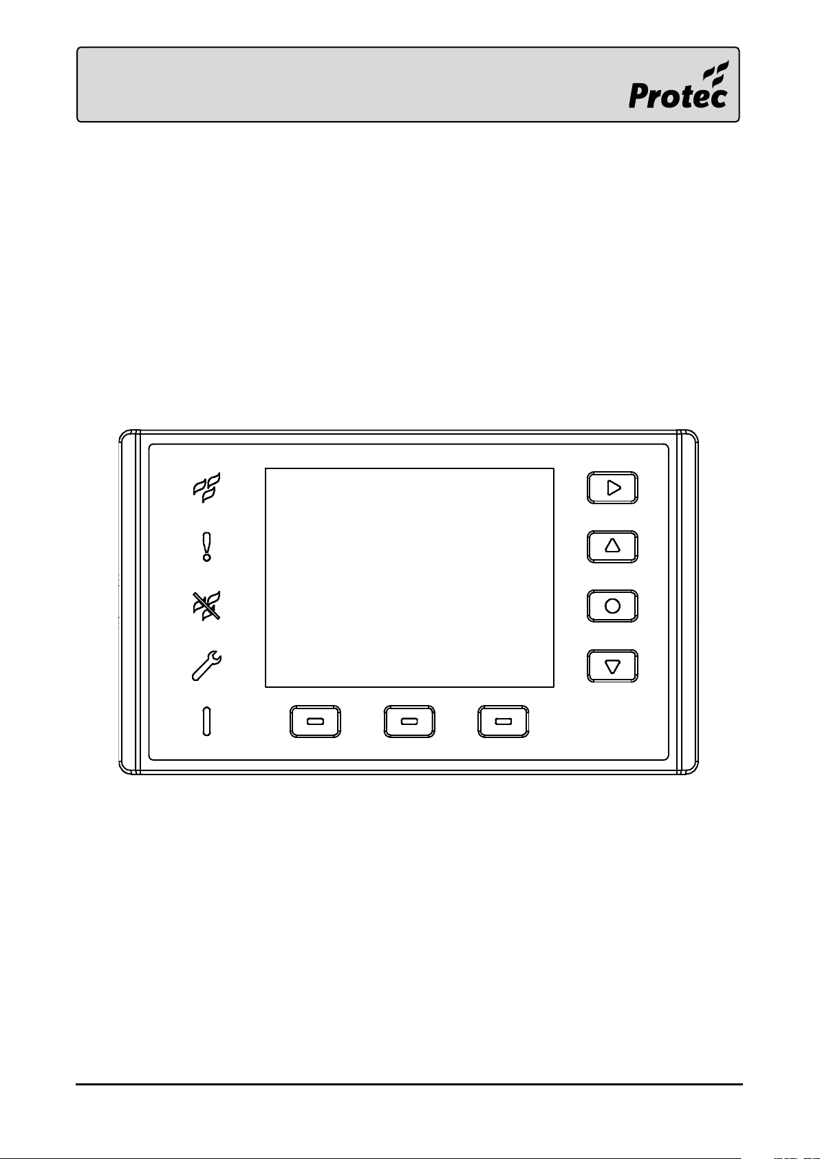
6000/LOOP/REPEATER
INSTALLATION AND USER GUIDE
Page 2
Issue
Modification Details
Author
Date
0
Document creation
AA
07/02/2017
1
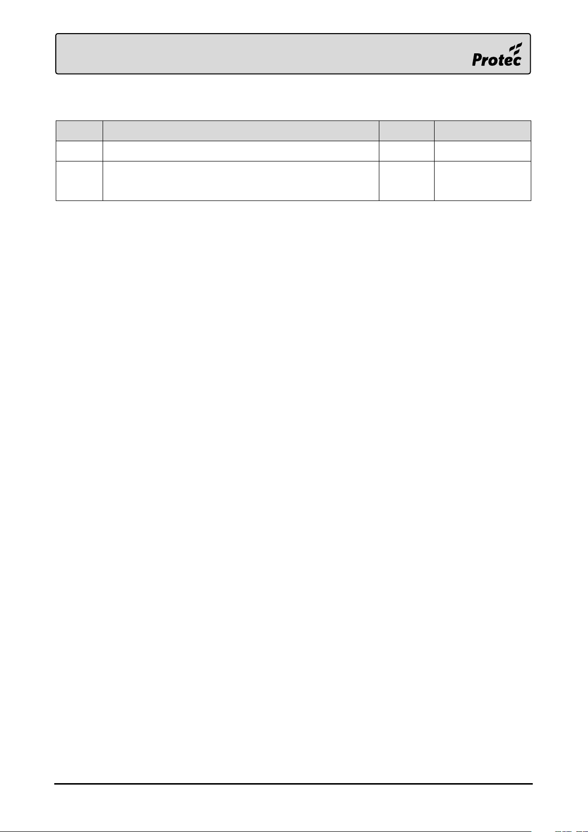
Added default access codes, updated the programming
guide
AA
05/10/2017
Document Revision Details
Notice
This manual may be revised as a result of enhancements to the device software or hardware. Check
for revisions to this manual, and download them, from the website. www.protec.co.uk
RDM0012 Issue 1 AA Page 2 of 35 © Protec Fire Detection PLC 2017
Page 3

Table of Contents
TABLE OF CONTENTS ................................................................................................................................. 3
1.0 INTRODUCTION ............................................................................................................................... 4
2.0 GLOSSARY OF TERMS ....................................................................................................................... 4
3.0 PROGRAMMING GUIDE ................................................................................................................... 5
3.1 Programmable Items .......................................................................................................................... 5
3.2 PC / Laptop Requirements ................................................................................................................. 5
3.3 Items Required for Device Programming ........................................................................................ 5
3.4 Protec Stand Alone Repeater Programmer Software Installation ............................................... 6
3.5 Connecting the Device to the PC ..................................................................................................... 11
3.6 Updating the Device Firmware ........................................................................................................ 12
3.7 Programming Device Custom Data and Logos ............................................................................. 14
4.0 INSTALLATION GUIDE ................................................................................................................... 18
4.1 Packaging Contents ........................................................................................................................... 18
4.2 Front Panel Removal ......................................................................................................................... 19
4.3 Mounting ............................................................................................................................................. 20
4.4 Insulation and Continuity Testing of Cabling ................................................................................ 21
4.5 Connecting the Front Panel .............................................................................................................. 21
4.6 Fitting the Front Panel ....................................................................................................................... 22
5.0 USER RESPONSIBILITIES ............................................................................................................... 23
5.1 Requirements of the Premises Management Named Person .................................................... 23
6.0 ROUTINE TESTING OF THE DEVICE ............................................................................................... 24
6.1 Daily Inspection .................................................................................................................................. 24
6.2 Weekly Test ......................................................................................................................................... 24
7.0 USER GUIDE .................................................................................................................................... 25
7.1 Controls ............................................................................................................................................... 25
7.2 LED Indicators .................................................................................................................................... 25
7.3 Push Buttons ...................................................................................................................................... 26
7.4 Access Levels ...................................................................................................................................... 26
7.5 Browsing System Events ................................................................................................................... 27
7.6 Help Menu ........................................................................................................................................... 28
7.7 Access Level 1 Controls Menu .......................................................................................................... 29
8.0 ENGINEER MENU GUIDE ............................................................................................................... 30
8.1 Login to Access Level 3...................................................................................................................... 30
8.2 Change the GUI Language ............................................................................................................... 31
8.3 Event Category Enablement ............................................................................................................. 32
8.4 Default Access Codes ........................................................................................................................ 33
9.0 APPENDIX 1 - INSTALLATION TEMPLATE .................................................................................... 34
RDM0012 Issue 1 AA Page 3 of 35 © Protec Fire Detection PLC 2017
Page 4
1.0 Introduction
The 6000/LOOP/REPEATER is a low power Fire Alarm Repeat Display, designed to complement Protec’s
range of control panels. Events from the panel are displayed on the device’s LCD, providing system
indication to any loop connected location on a site. The device only requires a loop connection to
provide both power and data, no network cabling, or external power supply is required.
2.0 Glossary of Terms
GUI
Graphical User Interface, graphics displayed on the screen of the device for user interaction.
Device
Refers to the 6000/LOOP/REPEATER.
Protec
Refers to Protec Fire Detection PLC.
There are no user serviceable parts inside the 6000/LOOP/REPEATER.
This equipment has been manufactured in conformance with the requirements of all
applicable EU council directives and regulations.
Electrical or electronic devices that are no longer serviceable must be collected separately
and sent for environmentally compatible recycling (in accordance with the European
Waste Electrical and Electronic Equipment Directive). To dispose of old electrical or
electronic devices, you should use the return and collection systems put in place in the
country concerned.
The policy of Protec Fire Detection PLC is one of continuous improvement. As such we reserve the
right to make changes to product specifications at any time and without prior notice.
RDM0012 Issue 1 AA Page 4 of 35 © Protec Fire Detection PLC 2017
Page 5
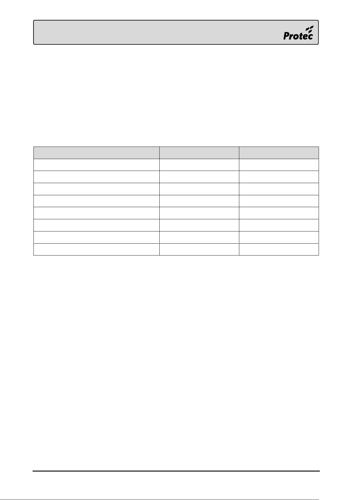
Item
Programming Software
Configure on Device
Bootloader Update
✖
✖
Firmware Update
✔
✖
Responsible Person and Installer Text
✔
✖
Level 2 & 3 Access Codes
✔
✔
Device GUI Language
✔
✔
Custom Site and Installer Logos
✔
✖
Device Home Screen Selection
✔
✔
Event Category Filtering
✔
✔
3.0 Programming Guide
The 6000/LOOP/REPEATER is programmed with a default configuration out of the box. If a custom
configuration is required, this can be programmed through the device’s USB port, using the Protec
Stand Alone Repeater Programmer windows software. The programming software also enables
updates of the device’s firmware if required. Note that some basic settings can also be configured on
the device itself through the engineer menu.
3.1 Programmable Items
The following items can be downloaded through the Protec Stand Alone Repeater Programmer.
3.2 PC / Laptop Requirements
The PC used to connect to the device must conform to the following minimum specification.
1 GHz processor (Intel ATOM processors are not recommended)
1 GB RAM (2GB for 64bit)
1 GB available hard disk space
One free USB 2.0 communications port (for connection to the device)
Windows® 7 or Windows® 10 (32bit or 64bit)
Windows® XP SP2 or SP3 (not recommended)
3.3 Items Required for Device Programming
Windows® PC of the aforementioned specification
Protec Stand Alone Repeater Programmer software
USB Type A Male to Micro-USB Type B Male cable (USB 2.0, max length 2m)
RDM0012 Issue 1 AA Page 5 of 35 © Protec Fire Detection PLC 2017
Page 6
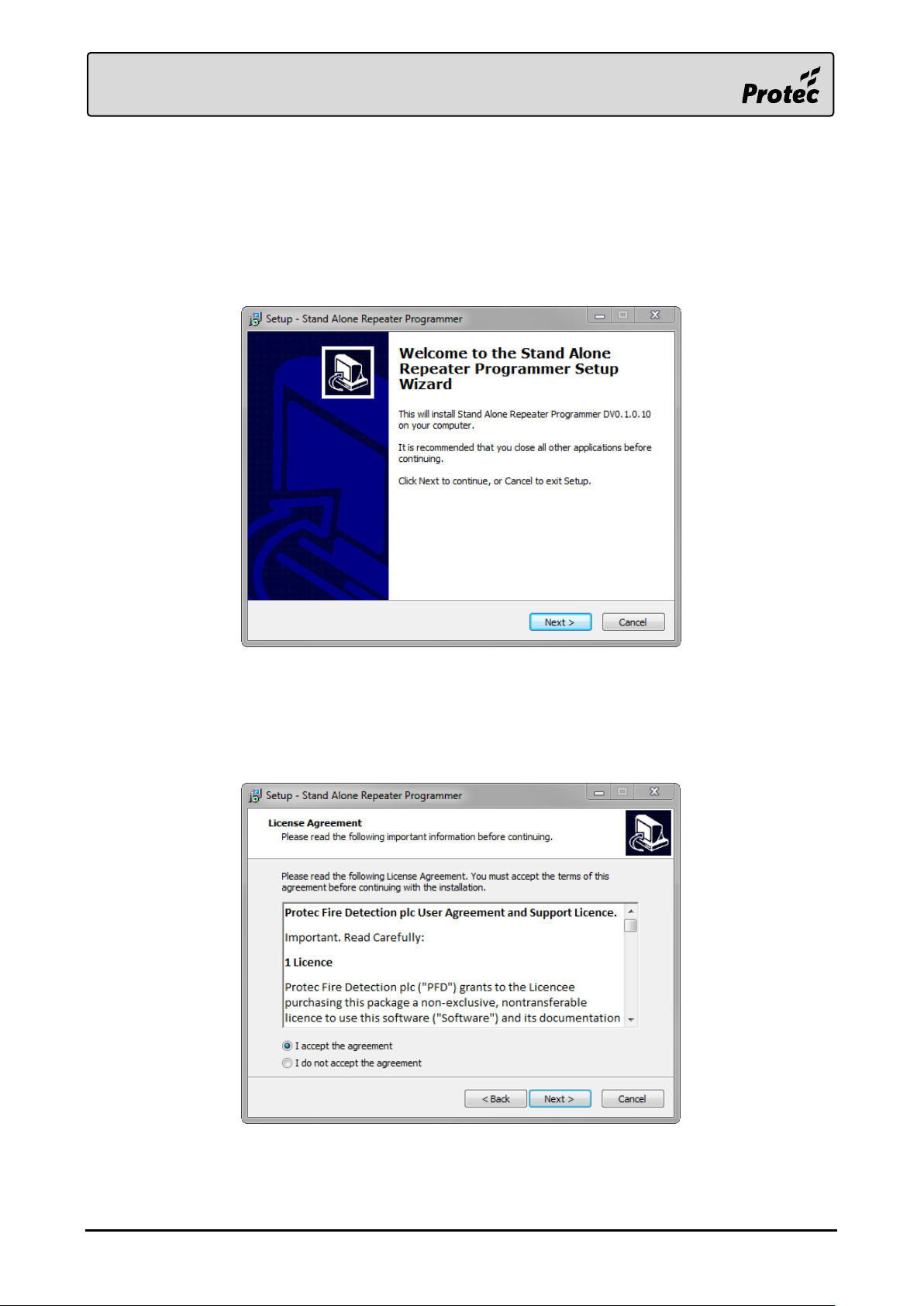
3.4 Protec Stand Alone Repeater Programmer Software Installation
The software executable can be obtained by contacting Protec Fire Detection, or visiting the Protec
website.
3.4.1 Opening the Executable Installer
Once the software has been obtained, double-click the executable file to open it.
Press ‘Next >‘ on the resulting window to start the installation.
3.4.2 Licence Agreement
Carefully read the licence agreement before continuing.
When happy with the agreement tick ‘I accept the agreement’ then press ‘Next >‘ to continue.
The installation cannot be completed without accepting this agreement.
RDM0012 Issue 1 AA Page 6 of 35 © Protec Fire Detection PLC 2017
Page 7
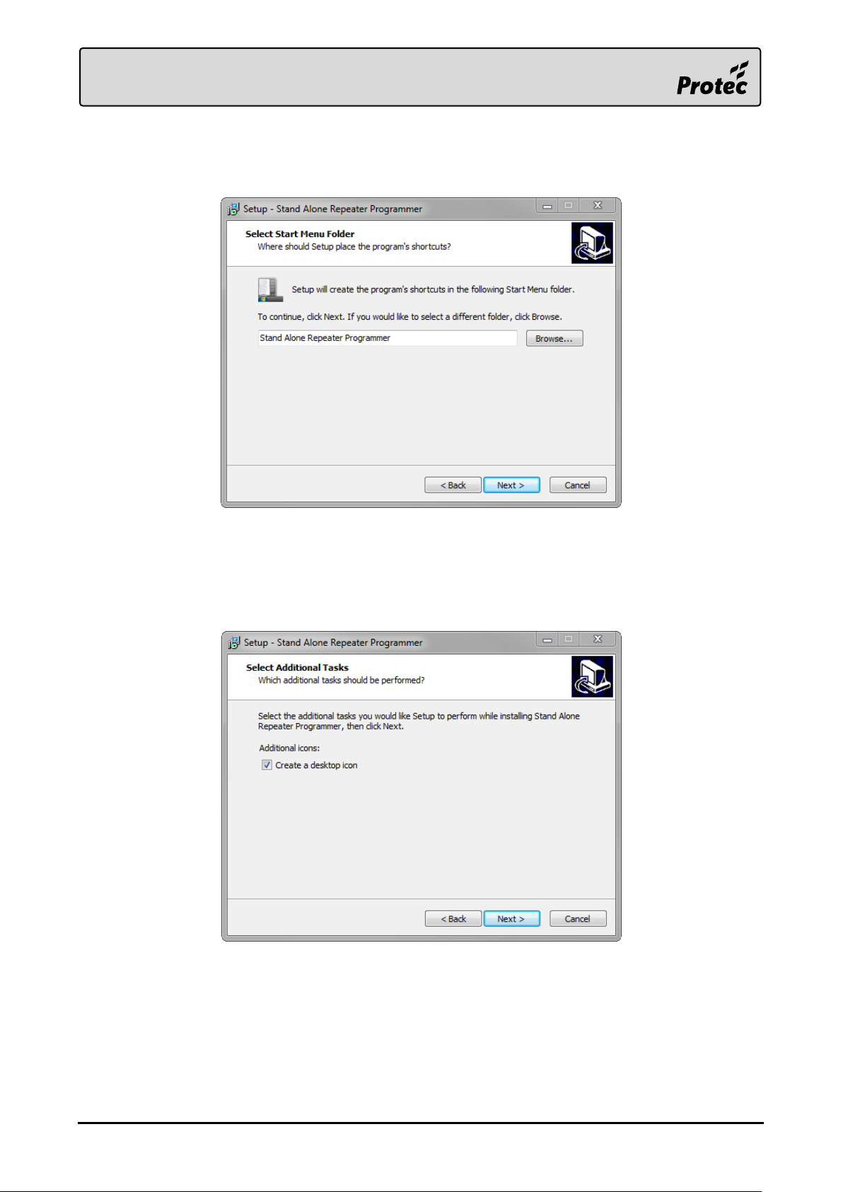
3.4.3 Start Menu Folder
It is possible to change the default Start Menu folder if required.
It is recommended to keep this as the default value set by the installer. Press ‘Next >‘ to continue.
3.4.4 Additional Tasks
It is possible to create a desktop icon for the Stand Alone Repeater Programmer.
It is recommended to create a desktop icon.
Tick ‘Create a desktop icon’ then press ‘Next >‘ to continue (this will begin the software installation).
RDM0012 Issue 1 AA Page 7 of 35 © Protec Fire Detection PLC 2017
Page 8
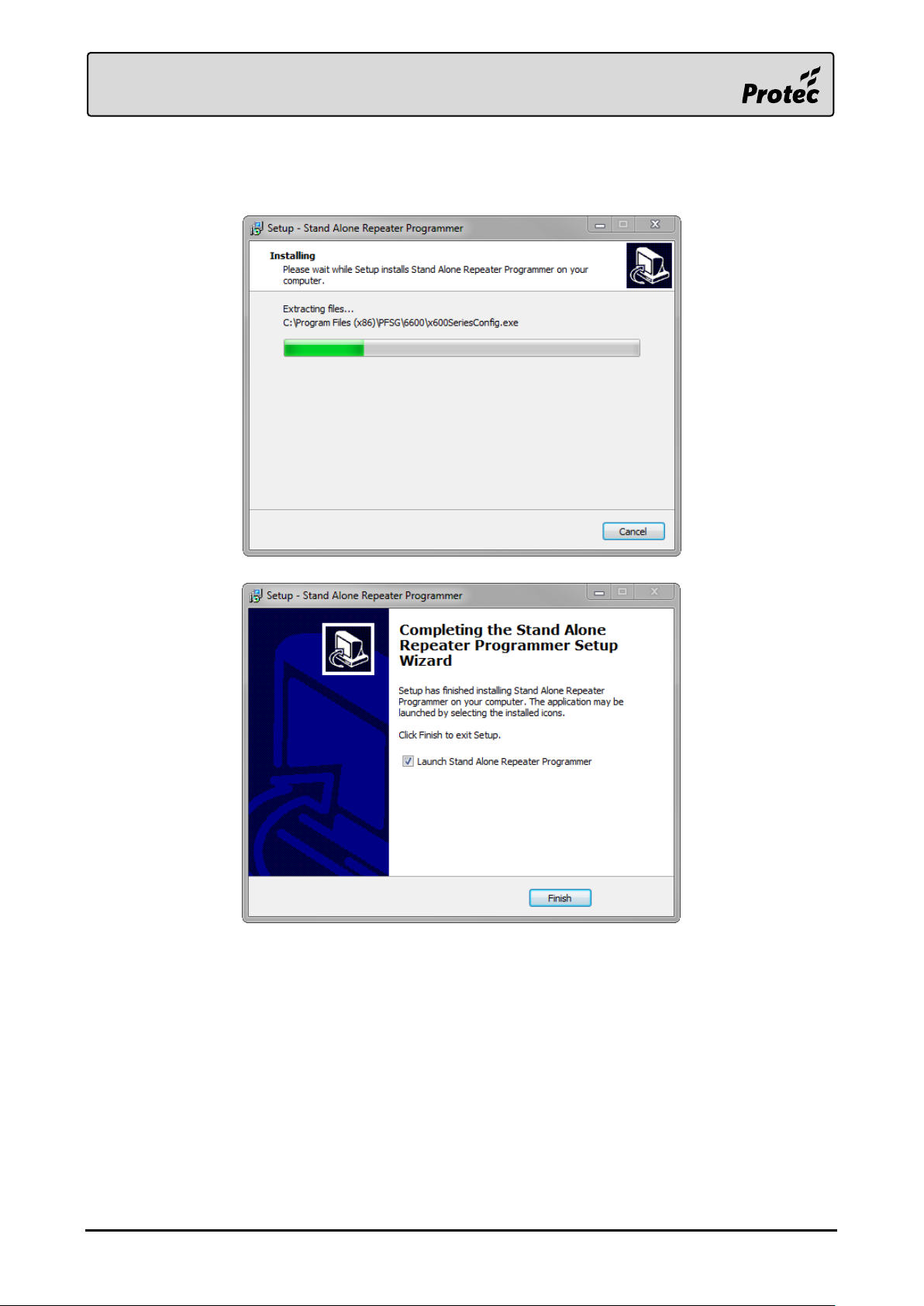
3.4.5 Installation
The Stand Alone Repeater Programmer will be installed on the system.
Once the installation is completed, the Stand Alone Repeater Programmer can be launched.
RDM0012 Issue 1 AA Page 8 of 35 © Protec Fire Detection PLC 2017
Page 9
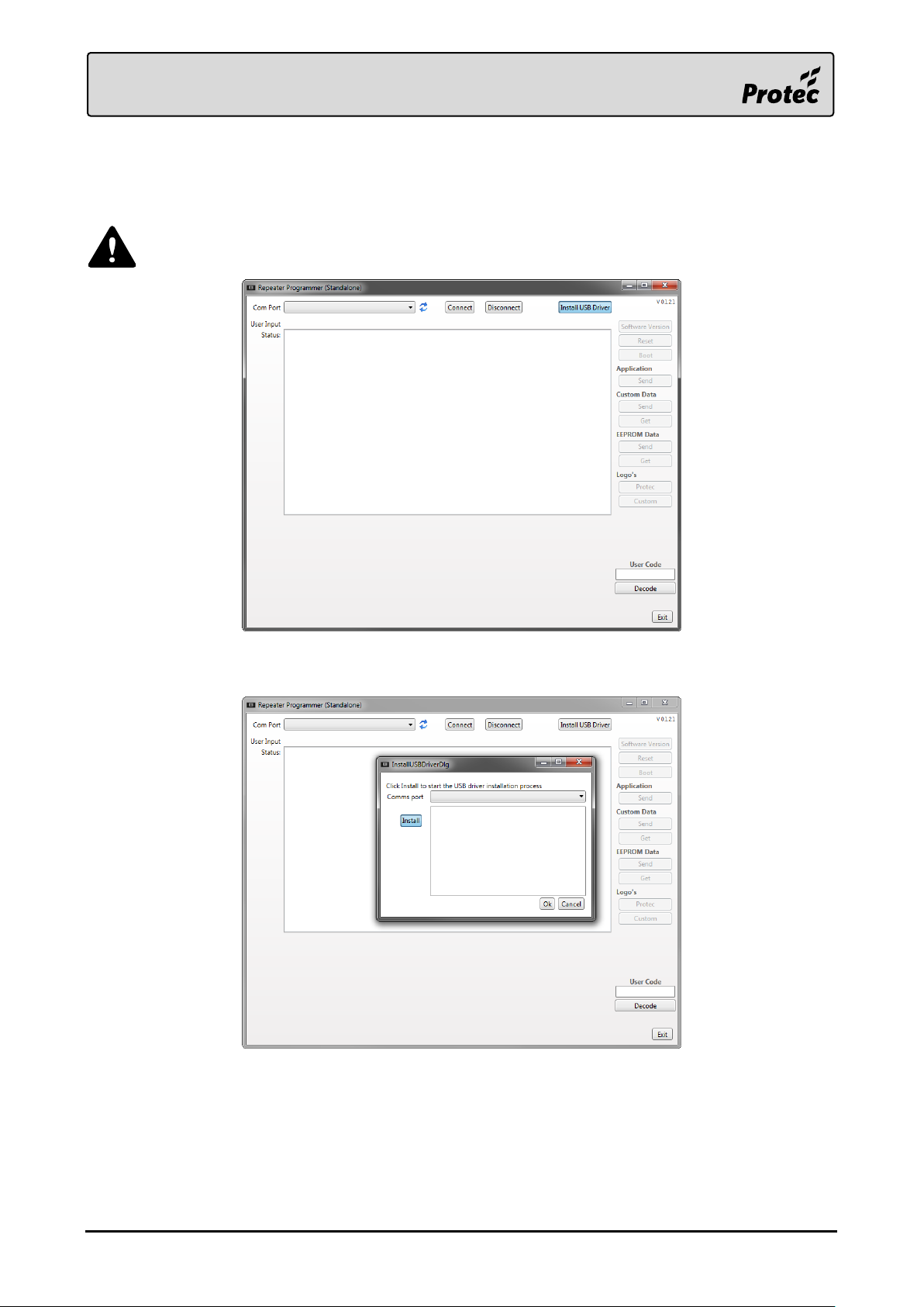
3.4.6 USB Driver Installation
The Stand Alone Repeater Programmer should now be installed and open. It is now required to install
the USB driver needed to communicate with the 6000/LOOP/REPEATER.
Ensure the device is not connected to the PC at this point.
Press ‘Install USB Driver’ in order to open the installation window.
Press ‘Install’ on the new window in order to start the driver installation.
Follow any on-screen prompts and accept any Windows User Account Control messages.
RDM0012 Issue 1 AA Page 9 of 35 © Protec Fire Detection PLC 2017
Page 10
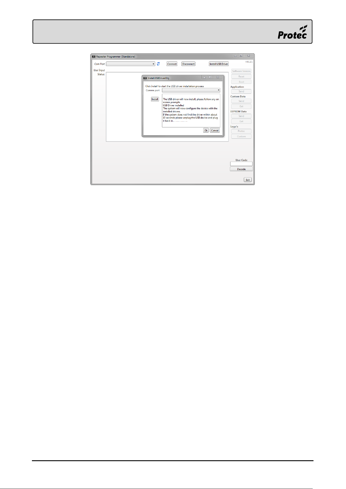
The USB driver should now be installed, and the device can now be connected to the PC. The USB
driver installation window can be closed.
RDM0012 Issue 1 AA Page 10 of 35 © Protec Fire Detection PLC 2017
Page 11
Ensure the device is
disconnected from the loop.
3.5 Connecting the Device to the PC
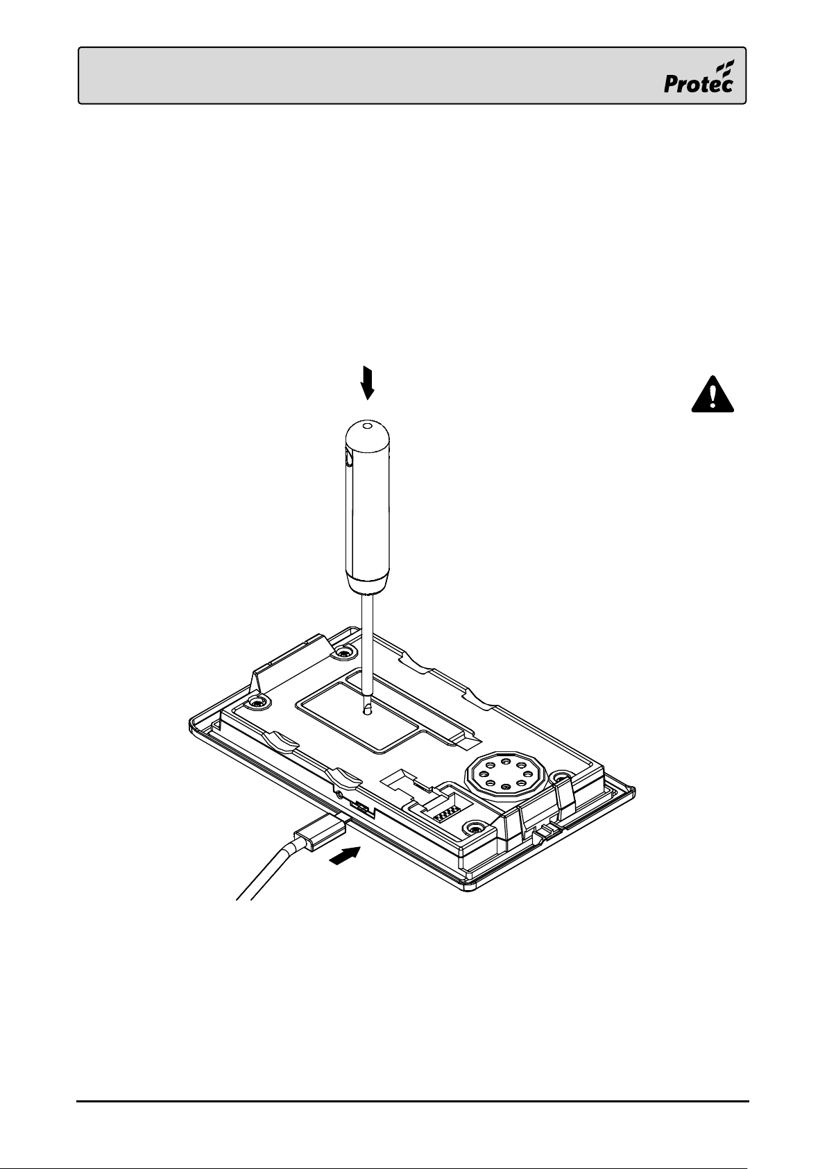
The 6000/LOOP/REPEATER must be completely disconnected from the loop and removed from the
back box before it can be updated. When removing the device from the back box, make sure the loop
continuity switch is set to the commissioning position to maintain the loop continuity.
Connect the USB cable to the PC
Using a small terminal screwdriver (e.g. 2.5mm), gently push and hold on the programming
switch through the area marked on the product label
Connect the Micro-USB cable to the device
Release the terminal screwdriver
If the connection is successful the device will appear blank (indicators and LCD not illuminated)
RDM0012 Issue 1 AA Page 11 of 35 © Protec Fire Detection PLC 2017
Page 12
3.6 Updating the Device Firmware
Occasionally new device firmware will be made available to introduce new features.
The new firmware can be programmed into the device using the Protec Stand Alone Repeater
Programmer.
Device Firmware must only be updated when instructed to do so by Protec.
Firmware files for the device will be supplied by Protec and have the suffix ‘.ptc’.
3.6.1 Device Connection
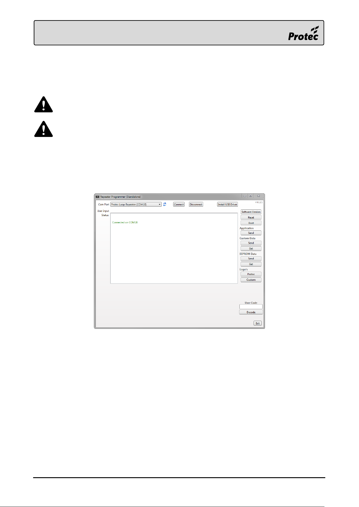
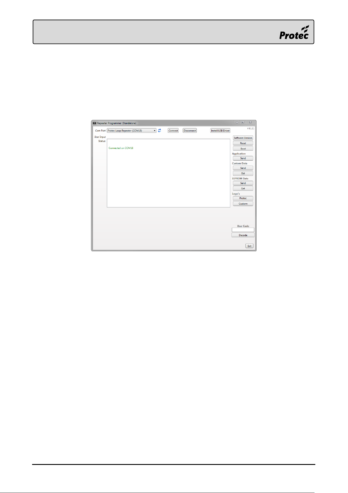
When the device is properly connected the status window should display ‘Connected on COMxx’.
Note: xx refers to the COM port the device is connected to (e.g. COM18), and may be different
between PCs.
RDM0012 Issue 1 AA Page 12 of 35 © Protec Fire Detection PLC 2017
Page 13
3.6.2 Downloading the Device Firmware
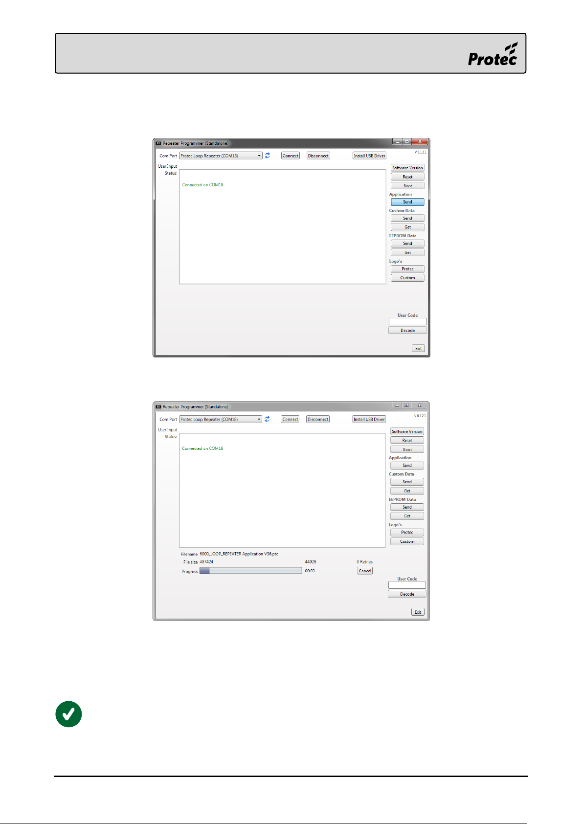
Press the ‘Application Send’ button to open the file navigator to open the firmware file.
Use the file navigator to find the .ptc firmware file required and press ‘Open’.
A progress bar will appear on the main window to show the transfer progress.
The firmware has been downloaded successfully once the status window reports ‘Transfer
Completed’.
To check the current software version of the device, press ‘Boot’ in the programming
software. The device will power up, and the current software version can be found within the
engineer menu. (Access Level 3). Note: the device will have to be reconnected again after
booting.
RDM0012 Issue 1 AA Page 13 of 35 © Protec Fire Detection PLC 2017
Page 14
3.7 Programming Device Custom Data and Logos
3.7.1 Device Connection
When the device is properly connected the status window should display ‘Connected on COMxx’.
Note: xx refers to the COM port the device is connected to (e.g. COM18), and may be different
between PCs.
RDM0012 Issue 1 AA Page 14 of 35 © Protec Fire Detection PLC 2017
Page 15
Downloading Responsible Person and Installer Information
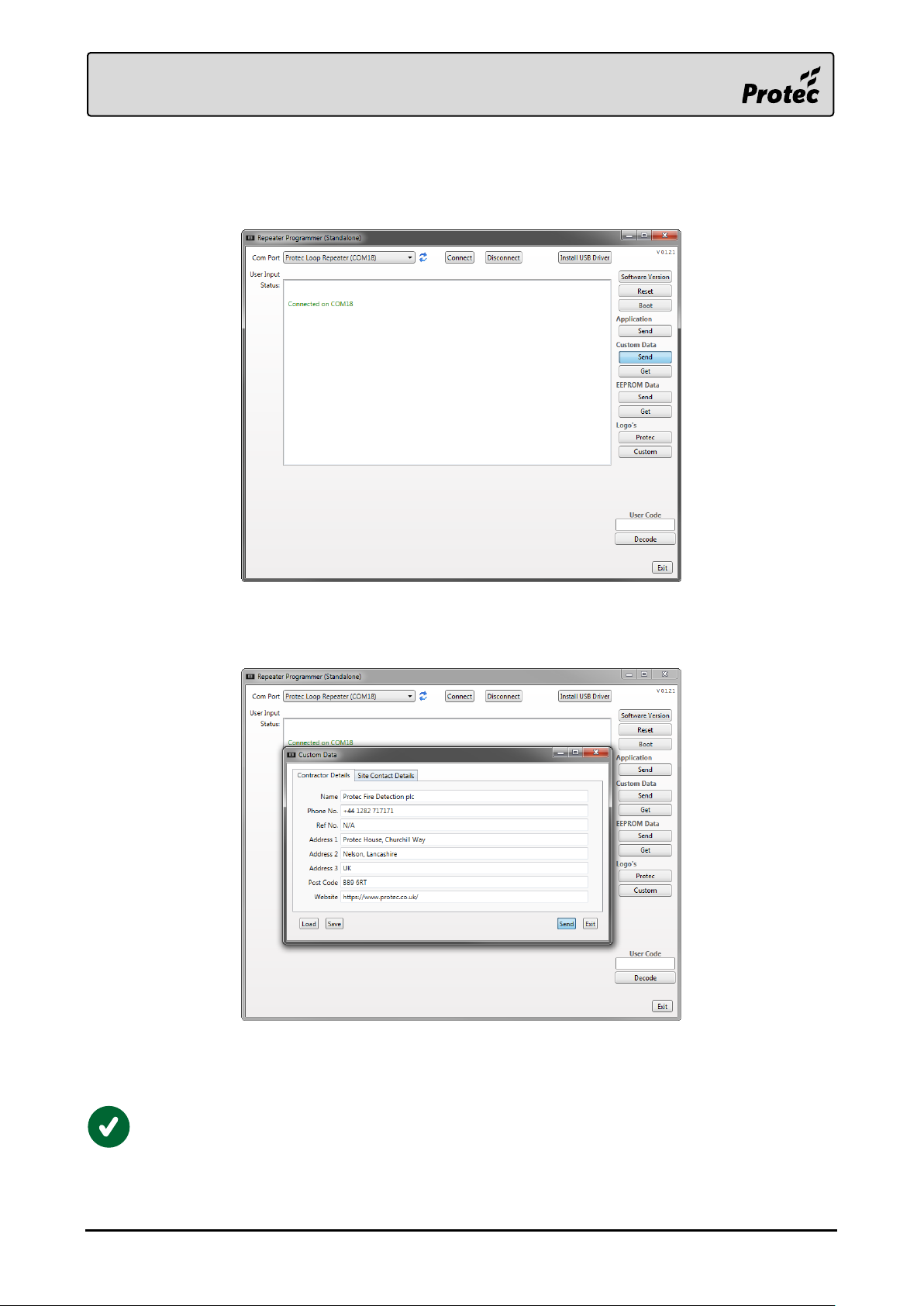
Press the ‘Custom Data Send’ button to open a window to enter the Premises Management Named
Person, and Installer information.
Fill in the fields of the form under the ‘Contractor Details’ and ‘Site Contact Details’ tabs.
Then press ‘Send’ to download the information to the device.
A progress bar will appear on the main window to show the transfer progress.
The information has downloaded successfully once the status window reports ‘Transfer Completed’.
To check the current custom data stored in the device, press ‘Custom Data Get’ in the
programming software.
RDM0012 Issue 1 AA Page 15 of 35 © Protec Fire Detection PLC 2017
Page 16
3.7.2 Downloading Custom Logos to the Device
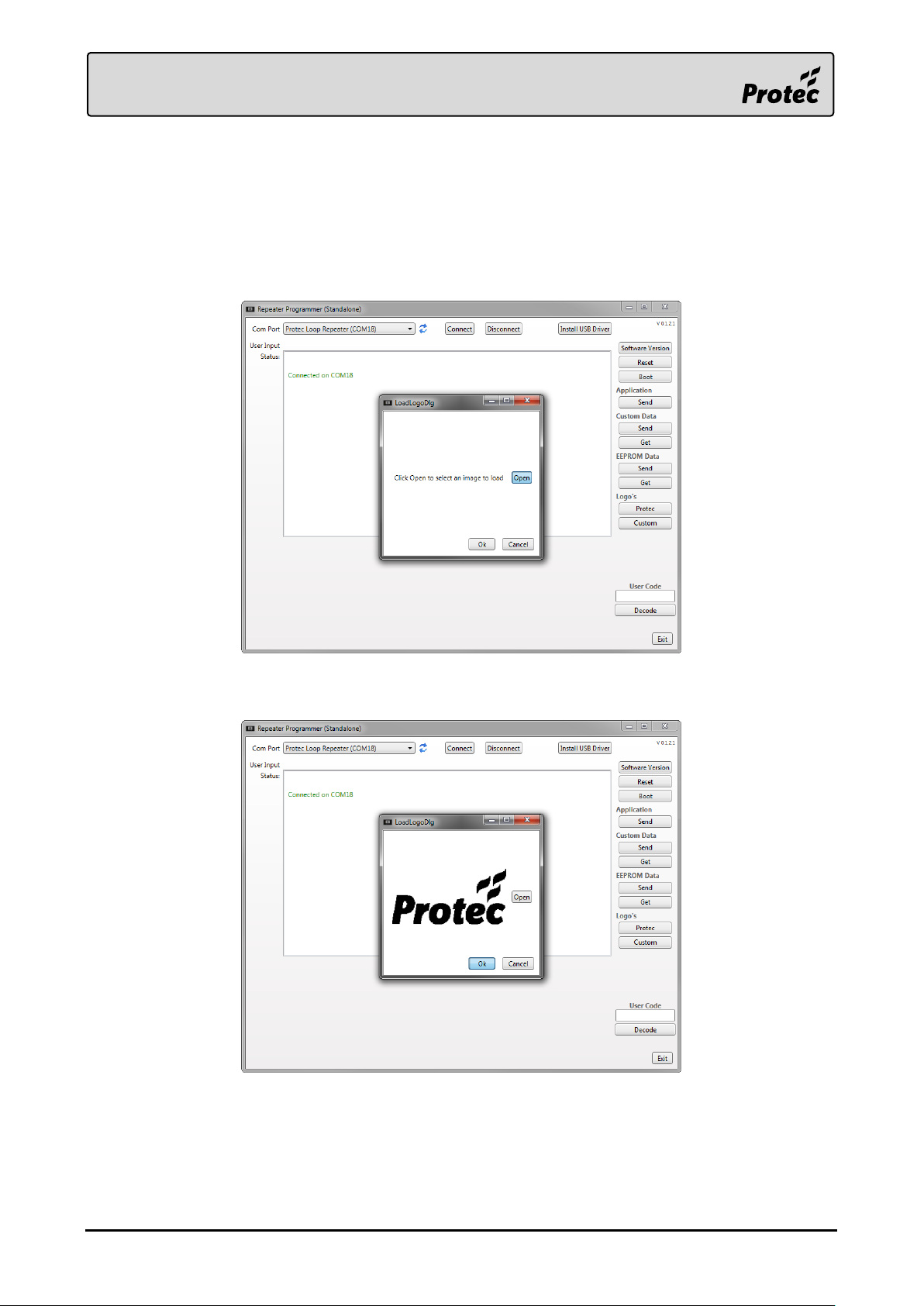
The 6000/LOOP/REPEATER is able to display custom logos on the home screen.
The images must be 200px wide by 100px tall, black and white images, of a .bmp or .png format.
Press the ‘Logo’s Protec’ or the ‘Logo’s Custom’ button to open the file navigator to browse for the
logo image file. Which logo is displayed on the device itself is chosen in the device’s EEPROM data.
Once the logo is loaded, and the preview is correct, press ‘Ok’ to start the transfer.
A progress bar will appear on the main window to show the transfer progress.
The logo has downloaded successfully once the status window reports ‘Transfer Completed’.
RDM0012 Issue 1 AA Page 16 of 35 © Protec Fire Detection PLC 2017
Page 17
3.7.3 Downloading the Device EEPROM Data
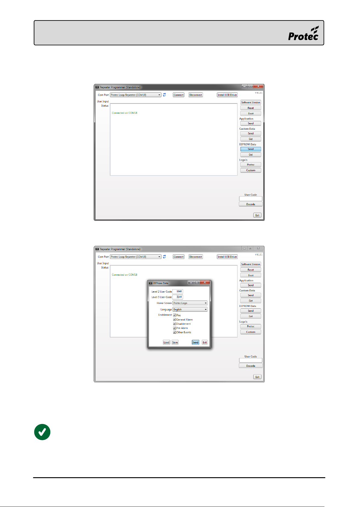
Press the ‘EEPROM Data Send’ button to enter the device’s EEPROM settings.
Fill in the fields of the form, then press ‘Send’ to download the information to the device.
A progress bar will appear on the main window to show the transfer progress.
The EEPROM data has been downloaded successfully once the status window reports ‘Transfer
Completed’.
To check the current EEPROM data stored in the device, press ‘EEPROM Data Get’ in the
programming software.
RDM0012 Issue 1 AA Page 17 of 35 © Protec Fire Detection PLC 2017
Page 18
4.0 Installation Guide
The device may be surface or flush mounted (no extra bezel is required when flush mounting).
The 6000/LOOP/REPEATER front panel is fully enclosed within a sealed housing. This housing must
never be opened. If the device requires repair it must be returned to Protec.
This equipment is not guaranteed unless installed and commissioned by a suitably trained
person in accordance with current national standards.
The device must be located internally in an area that is not subject to dampness, direct
sunlight, extremes of temperature or physical abuse.
4.1 Packaging Contents
1x 6000/LOOP/REPEATER Device
3x No.8-10-12 Wall Plugs
3x No.8 x 1.5" Round Head Pozi-Drive Woodscrews
2x Opening Tools
2x 2.2mm x 10mm Pan-Head T6 Plas Tech Locking Screws
RDM0012 Issue 1 AA Page 18 of 35 © Protec Fire Detection PLC 2017
Page 19
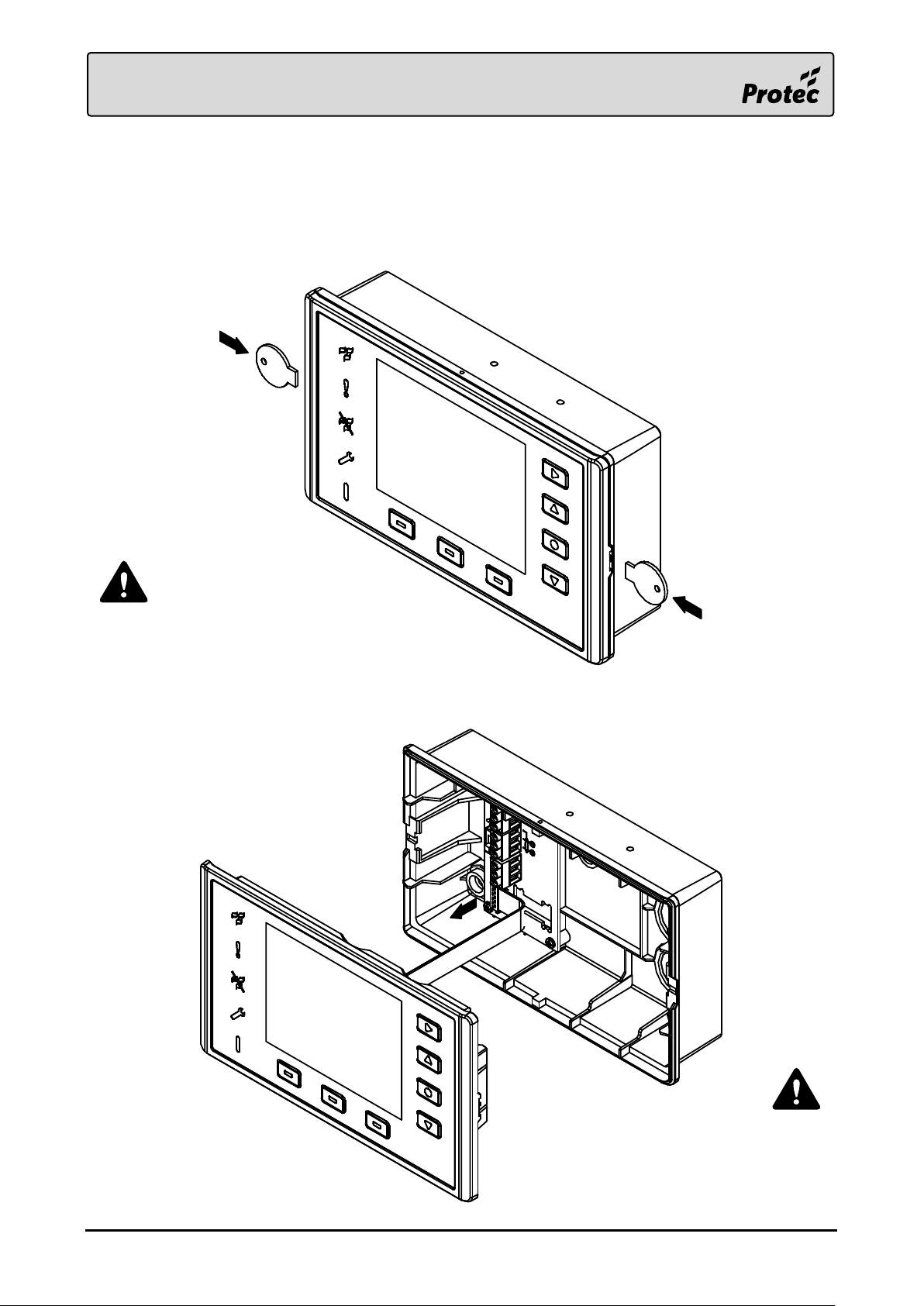
Place the front panel in a
safe area, such as the
original packaging, until it
is required.
Ensure both clasps are disengaged before
the front panel is pulled from the back box.
Carefully remove the assembly to avoid
damage to the ribbon cable.
4.2 Front Panel Removal
Carefully push the Opening Tools into the clasps on the sides of the enclosure, an audible click should
be heard when the clasps disengage. Gently pull the assembly out of the back box, whilst being
cautious of the ribbon cable located behind. Carefully pull the ribbon cable, by the connector, from the
terminal board, leaving it connected to the front panel.
RDM0012 Issue 1 AA Page 19 of 35 © Protec Fire Detection PLC 2017
Page 20
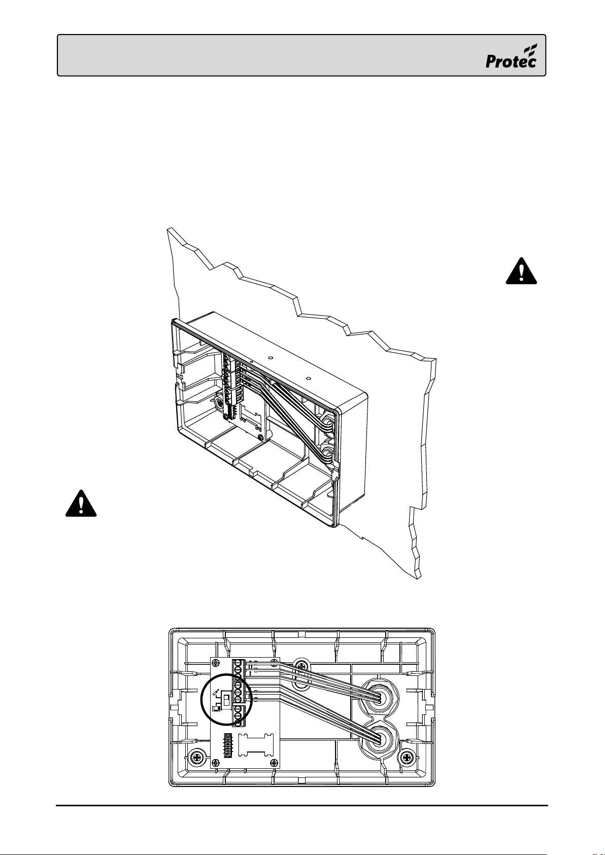
Only use the cable entry
points provided.
Ensure conductors are as flat to the back
box as possible, whilst respecting the
cable manufacturer’s recommended
minimum bend radius.
4.3 Mounting
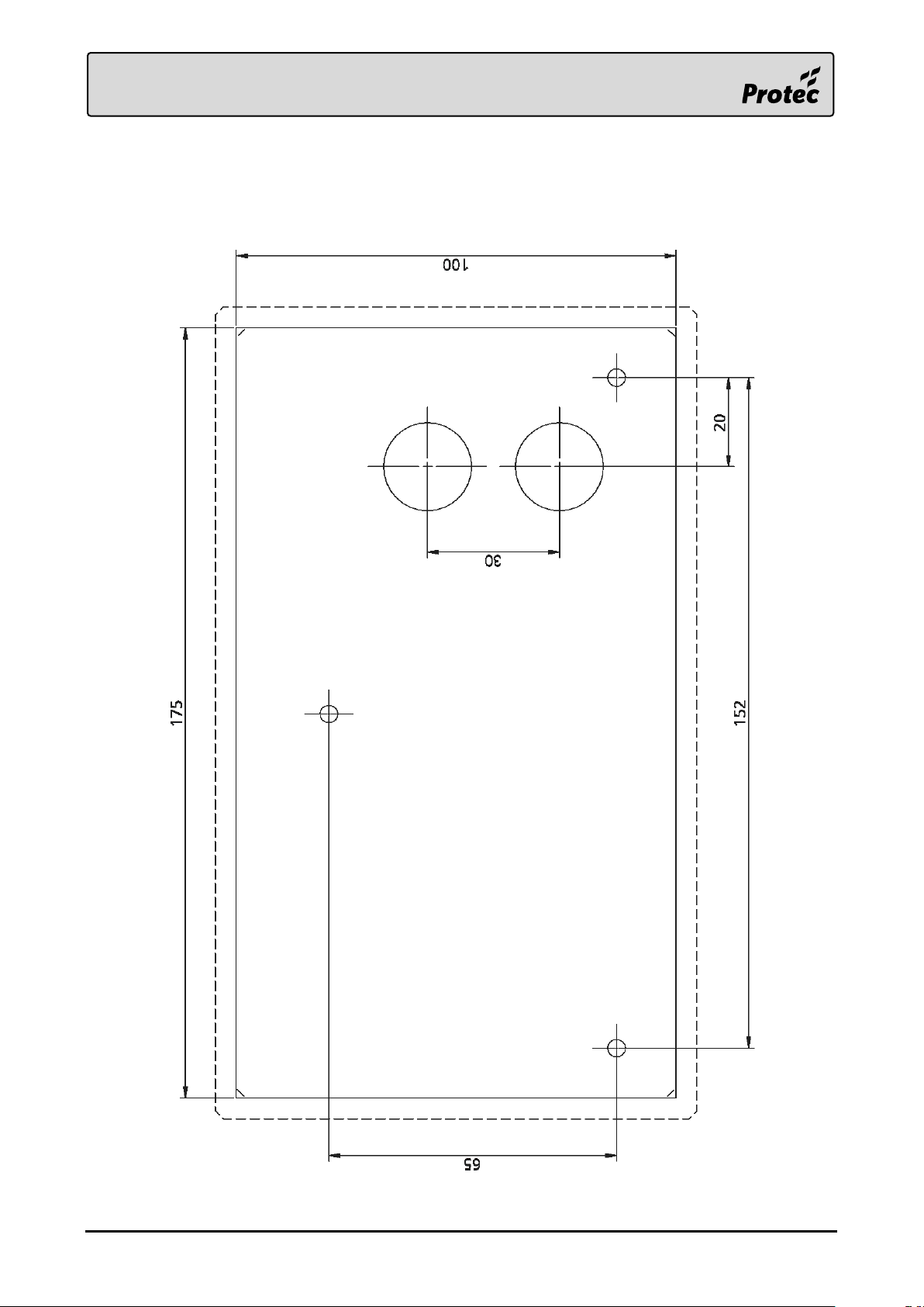
Use the installation template, provided at the end of the document, to mark out the fixing
points, then drill and plug the holes as marked.
Using a 20mm hole-saw, drill the required entry points in the back box. Feed the Loop wiring
into the enclosure using suitable glands.
Strip the cable sheaths at the entrance to the box, only run individual conductors within the
box.
Carefully screw the back box to the fixing points, taking care not to overtighten the screws.
Terminate the conductors to the correct terminals.
Set the loop continuity switch on the terminal board to the commissioning position whilst the
front panel is removed.
RDM0012 Issue 1 AA Page 20 of 35 © Protec Fire Detection PLC 2017
Page 21
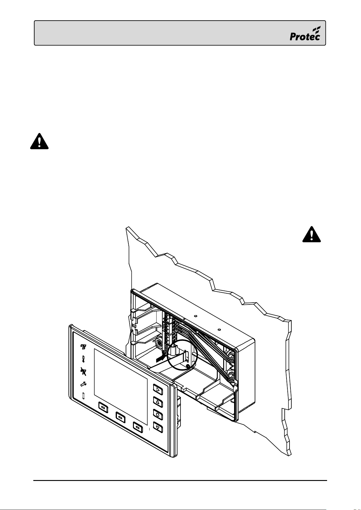
Reset the loop continuity switch on
the terminal board back to the
running position.
4.4 Insulation and Continuity Testing of Cabling
Whilst the front panel is removed and the loop continuity switch is in the commissioning position,
cable insulation and continuity tests may be performed if required.
Tests should be carried out using a 500V DC insulation tester (‘Megger’). If tests are performed the
insulation readings between each cable core, and each cable core and earth must be greater than
10MΩ.
The front panel must not be connected when high voltage insulation tests are being
performed on the cabling. The cabling must be completely discharged prior to connection
to the front panel. Equipment connected to the cabling during testing will be damaged
by the high voltages used, invalidating any warranty.
4.5 Connecting the Front Panel
Connect the ribbon cable to the terminal board. The terminal board has an integral cable restraint,
push the ribbon gently into the slot on the board as show below. The ribbon should curve neatly
beneath the terminal board. Reset the loop continuity switch on the terminal board back to the
running position. Failing to do so may compromise loop fault detection, the front panel will report this
as an error.
RDM0012 Issue 1 AA Page 21 of 35 © Protec Fire Detection PLC 2017
Page 22
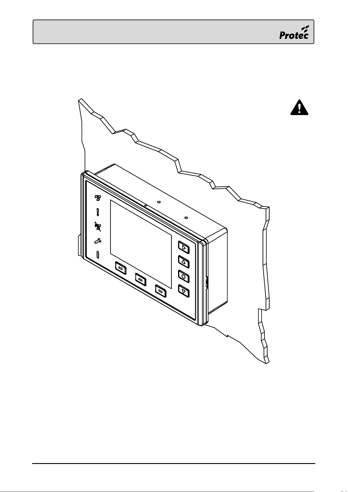
Do not apply pressure to the LCD as
damage may occur. Push the front
panel using only the plastic bezel.
4.6 Fitting the Front Panel
Once the ribbon cable is connected and the loop continuity switch is in the running position, push the
front panel onto the back box. An audible click should be heard from both sides of the enclosure as
the clasps engage. A light tug on the front panel confirms that it has fully mated with the back box.
RDM0012 Issue 1 AA Page 22 of 35 © Protec Fire Detection PLC 2017
Page 23
5.0 User Responsibilities
The registered owner of the fire alarm system has specific responsibilities regarding the installation,
testing and maintenance of the fire alarm system.
BS5839 Pt 1: 2017 Section 7 states that the user of the fire alarm system must appoint a single named
person to supervise all matters regarding the fire alarm system.
Summarised below are the responsibilities expected of the named person.
It is strongly advised that a full copy of BS5839 Pt 1: 2017 is obtained and thoroughly
read and understood.
5.1 Requirements of the Premises Management Named Person
Ensure that the fire alarm equipment is checked at least once every 24 hours to ensure there
are no faults on the system. Report any faults to the site maintenance manager.
Ensure that arrangements are in place for correct testing of the fire alarm system (as specified
in BS5839 Pt 1: 2017 Section 6, summarised in section 6.0 of this document).
Ensure that the system event log is kept up to date and is available for inspection by any
authorised person when required.
Ensure that all occupants of the protected premises are trained how to use the system
properly and that they are aware of what action to take in the event of an alarm.
Ensure that false alarms are minimised.
Ensure all detectors and manual call points are not obstructed. Detectors must have at least
500mm clear space preserved in all directions around them.
Establish a liaison with those responsible for changes in, or maintenance of the building fabric.
Ensure that when changes are made to the system, record drawings and operating
instructions are updated.
Ensure that, where necessary, a suitable zone plan is displayed and kept up to date.
Ensure that any relevant spare parts for system maintenance are held within the premises.
RDM0012 Issue 1 AA Page 23 of 35 © Protec Fire Detection PLC 2017
Page 24

6.0 Routine Testing of the Device
Recommendations for testing of the system are detailed in BS5839 Pt 1: 2017 Section 6.
The routine testing for the device is briefly detailed below.
6.1 Daily Inspection
Check that the Supply Present indicator is illuminated.
Check for any faults on the system and report these to the site maintenance manager.
6.2 Weekly Test
Perform the daily test recommended in 6.1.
Perform an indicator test (lamp test) to check the integrity of the front panel indications, and
internal buzzer.
RDM0012 Issue 1 AA Page 24 of 35 © Protec Fire Detection PLC 2017
Page 25
LED Indicator
Flashing (1Hz)
Solid
Fire
New Fire Event/s
Accepted Fire Event/s
Fault
New Fault Event/s
Accepted Fault Event/s
Disablement
New Disablement Event/s
Accepted Disablement Event/s
Power - Device Supply OK
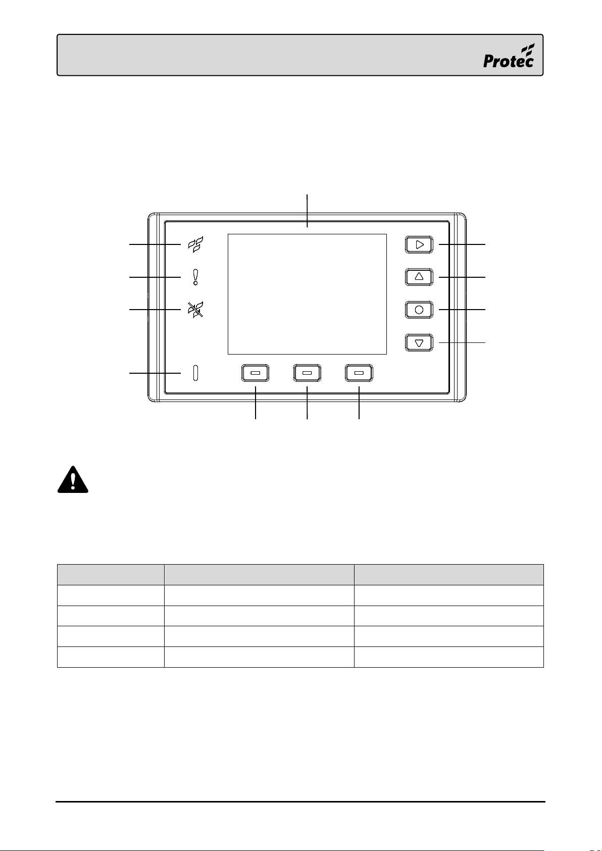
4.4” LCD
Next
Up
Select
Down
Context 3Context 2Context 1
Fire LED
Fault LED
Disablement LED
Power LED
7.0 User Guide
7.1 Controls
The 6000/LOOP/REPEATER status indicators and controls are shown below.
7.2 LED Indicators
The LED indicators display the following general system statuses.
During normal operation, the LCD picture will be inverted for a short period of time at
regular intervals. This is implemented to extend the lifetime of the LCD and reduce
burn-in.
RDM0012 Issue 1 AA Page 25 of 35 © Protec Fire Detection PLC 2017
Page 26
Push Button
Function
Next ►
Next Sub-Menu
Up ▲
Scroll List Up
Select ●
Select List Item
Down ▼
Scroll List Down
Context 1
Context Specific. Function depends on the current menu.
Context 2
Context Specific. Function depends on the current menu.
Context 3
Open/Close ‘Controls’ Menu
7.3 Push Buttons
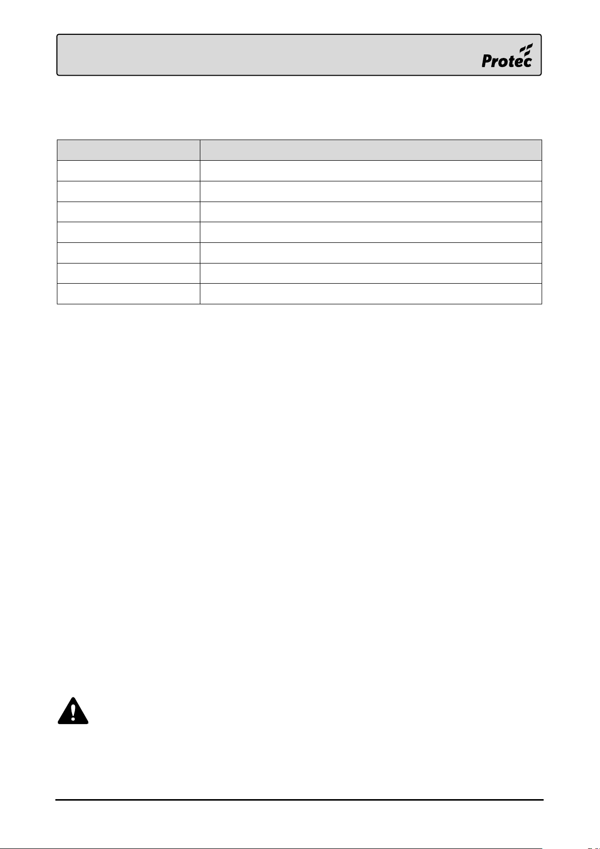
The device’s push buttons are used for the following functions.
7.4 Access Levels
7.4.1 Access Level 1 (General User)
Access level 1 allows the general user to view the status of the system at any time.
The following functions may be performed at access level 1.
View the system status indications and LCD.
Accept the local system status, and mute the buzzer, by pressing 'Accept'.
Initiate a Lamp Test.
Enter access level 2
Enter access level 3
7.4.2 Access Level 2 (Authorised / Trained User)
Access level 2 currently provides no further functionality than access level 1 on this product.
7.4.3 Access Level 3 (Engineer)
Change GUI language
Change the device’s event category filtering
Change level 2 & 3 access codes
Select the displayed home screen image
Disable the internal buzzer
Disable the ambient light sensor
Disable the display light
View the device’s serial number, type number and software version number
Check the device’s flash memory condition
View device diagnostic statistics
As a security measure the 6000/LOOP/REPEATER will return to access level 1 if no key
activity has been detected for 5 minutes.
RDM0012 Issue 1 AA Page 26 of 35 © Protec Fire Detection PLC 2017
Page 27
A
B
C
D
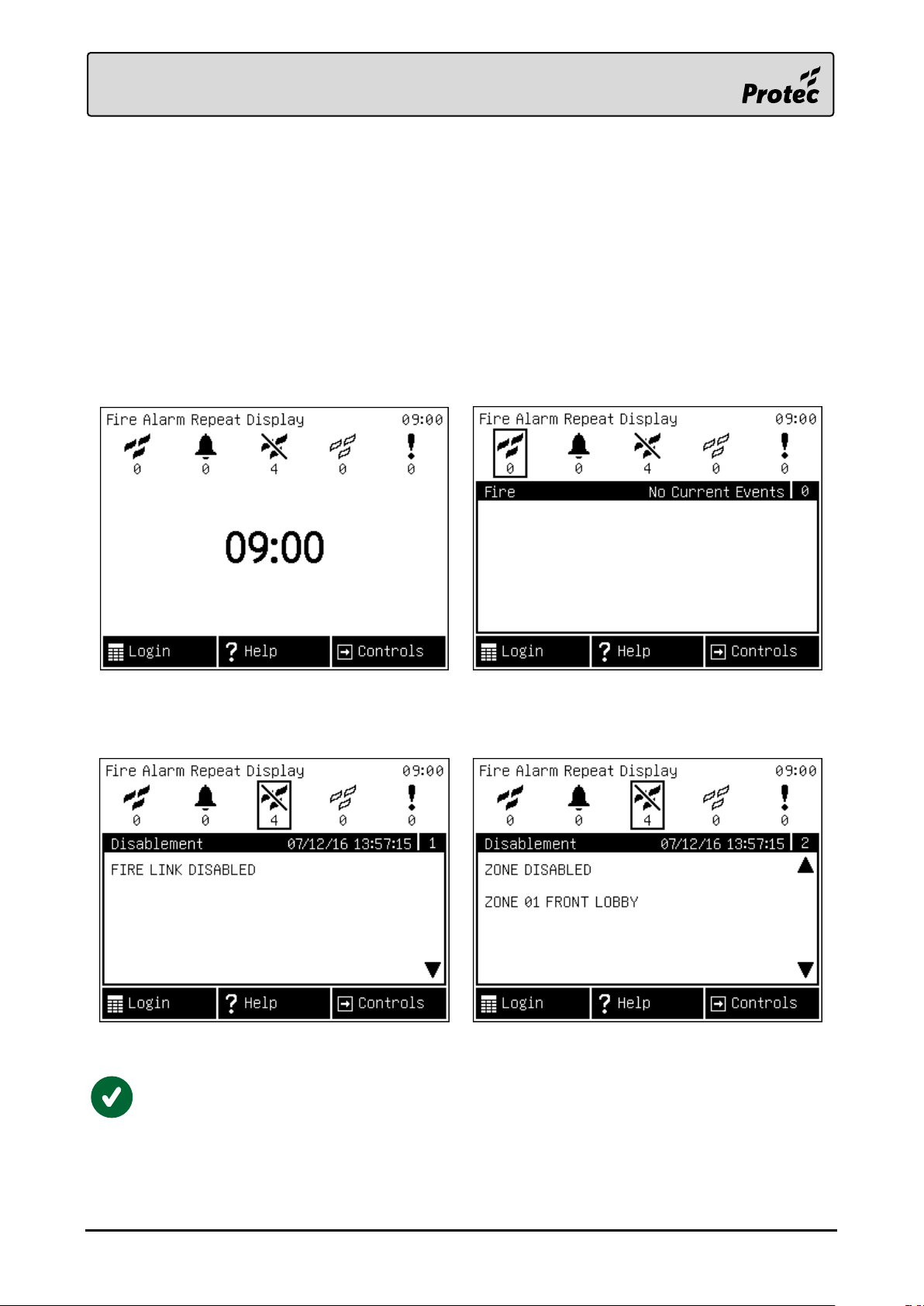
7.5 Browsing System Events
The system status can be browsed using the navigation controls.
A. Starting from the home screen.
B. Pressing the ‘Next’► button moves the display to first category of events.
C. Subsequent presses of the ‘Next’► button scrolls the display through each event category and
then returns to the home screen.
D. Pressing the ‘Up’▲ or ‘Down’▼ button, whilst displaying a category with more than one active
event, will scroll up and down the list.
The 6000/LOOP/REPEATER can display up to 30 events in each category, events are
displayed on a first in, first out basis. If more than 30 events of one type are on the
system the user must use the Fire Alarm Control Panel to view the entire list.
RDM0012 Issue 1 AA Page 27 of 35 © Protec Fire Detection PLC 2017
Page 28
7.6 Help Menu
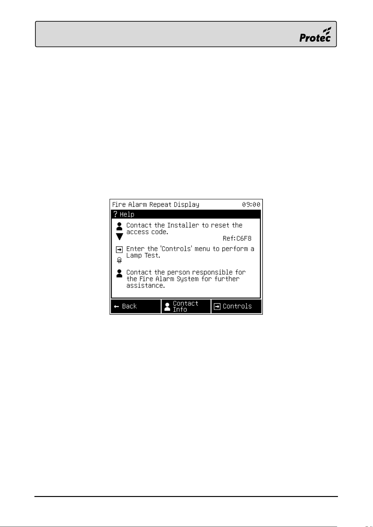
To enter the ‘Help’ menu, press Help at access level 1. The ‘Help’ menu shows device status
dependant tooltips, aiming to guide the user to accomplish tasks.
The tooltips display the controls to access a particular function of the device. For example, the ‘Lamp
Test’ tooltip, prompts the user to open the ‘Controls’ menu and press the ‘Lamp Test’ button through
the associated symbols.
Tooltips:
Emergency Access Code (after 3 consecutive failed login attempts)
Controls to perform a Lamp Test (always shown, but low priority)
Controls to view the Site Responsible Person contact details (always shown)
Controls to accept the system status and mute the internal buzzer (shown whilst a non-
accepted event is present)
7.6.1 Emergency Access Code
If the current access codes to the 6000/LOOP/REPEATER have been misplaced, or forgotten, it is
possible to obtain an emergency code to allow the Level 3 access code to be reset. After three failed
code entry attempts to the device a new tooltip will be generated in the ‘Help’ menu. A one off access
code can be obtained by contacting Protec then quoting the encoded key displayed in the tooltip, or
using the Stand Alone Repeater Programmer to decode the key. The encoded key is valid for one hour
from its generation and will only work once.
Alternatively the access codes can be re-programmed through the Stand Alone Repeater Programmer
although this requires disconnection from the loop, which must be undertaken by a suitably trained
person.
RDM0012 Issue 1 AA Page 28 of 35 © Protec Fire Detection PLC 2017
Page 29
7.7 Access Level 1 Controls Menu
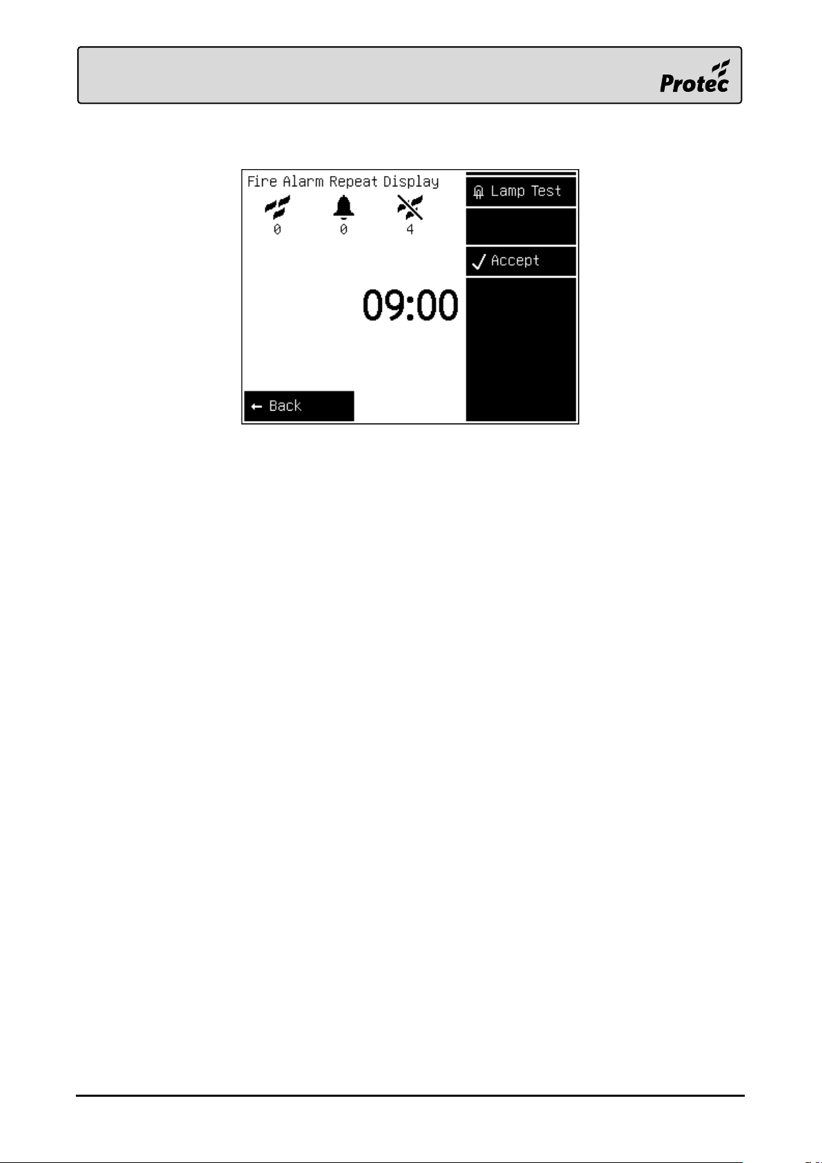
The ‘Controls’ menu is accessible at any time from all access levels. The menu adapts the navigation
buttons to allow the user to perform additional actions at any point. The following actions are
available on the 6000/LOOP/REPEATER. The menu will automatically time out after 10 seconds if no
further input is received.
7.7.1 Lamp Test
Perform a ‘Lamp Test’ to check the integrity of the front panel indications, the LCD and internal
buzzer. During the test, all of the indicators will light, the LCD will display all pixels black then white,
and the buzzer will sound. The sequence finishes after 10 seconds, during this time, no further user
input is processed.
7.7.2 Accept
Accept the local system status, and mute the buzzer. This is a local action which will not accept the
system status on the connected Fire Panel or devices.
RDM0012 Issue 1 AA Page 29 of 35 © Protec Fire Detection PLC 2017
Page 30
A
B
C
D
8.0 Engineer Menu Guide
Basic settings can be configured on the device itself through the engineer menu by a suitably trained
person. The menu is accessible once logged in to access level 3 on the device.
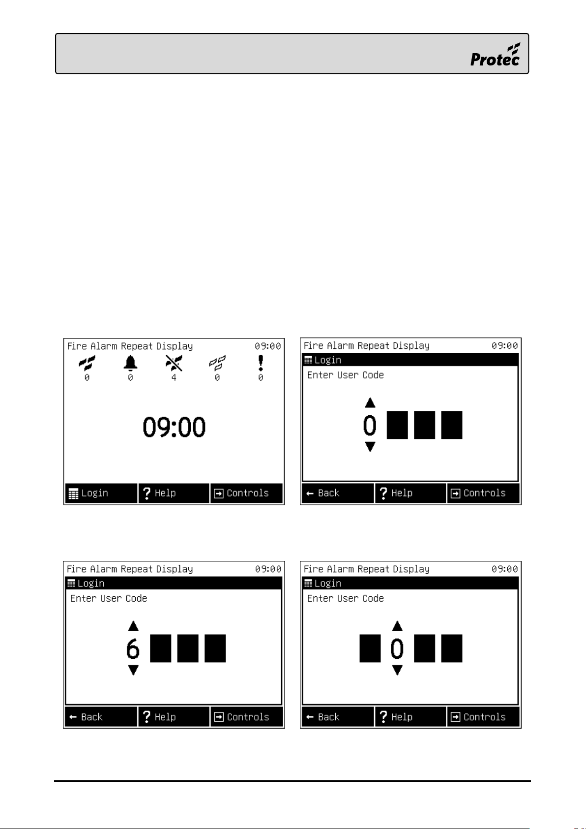
8.1 Login to Access Level 3
In order to access the engineer menu a suitably trained person must enter the level 3 access code.
A. Starting from the home or event screen.
B. Pressing the ‘Login’ button moves to the login screen.
C. Enter the level 3 access code by using the ‘Up’▲ and ‘Down’▼ buttons to cycle the currently
visible digit.
D. Press the ‘Select’● button to accept the digit and then move to the next.
E. Repeat until the entire code is entered. If the code was correct the engineer menu will be
opened, otherwise the device will return to the previous screen.
RDM0012 Issue 1 AA Page 30 of 35 © Protec Fire Detection PLC 2017
Page 31
A
B
C
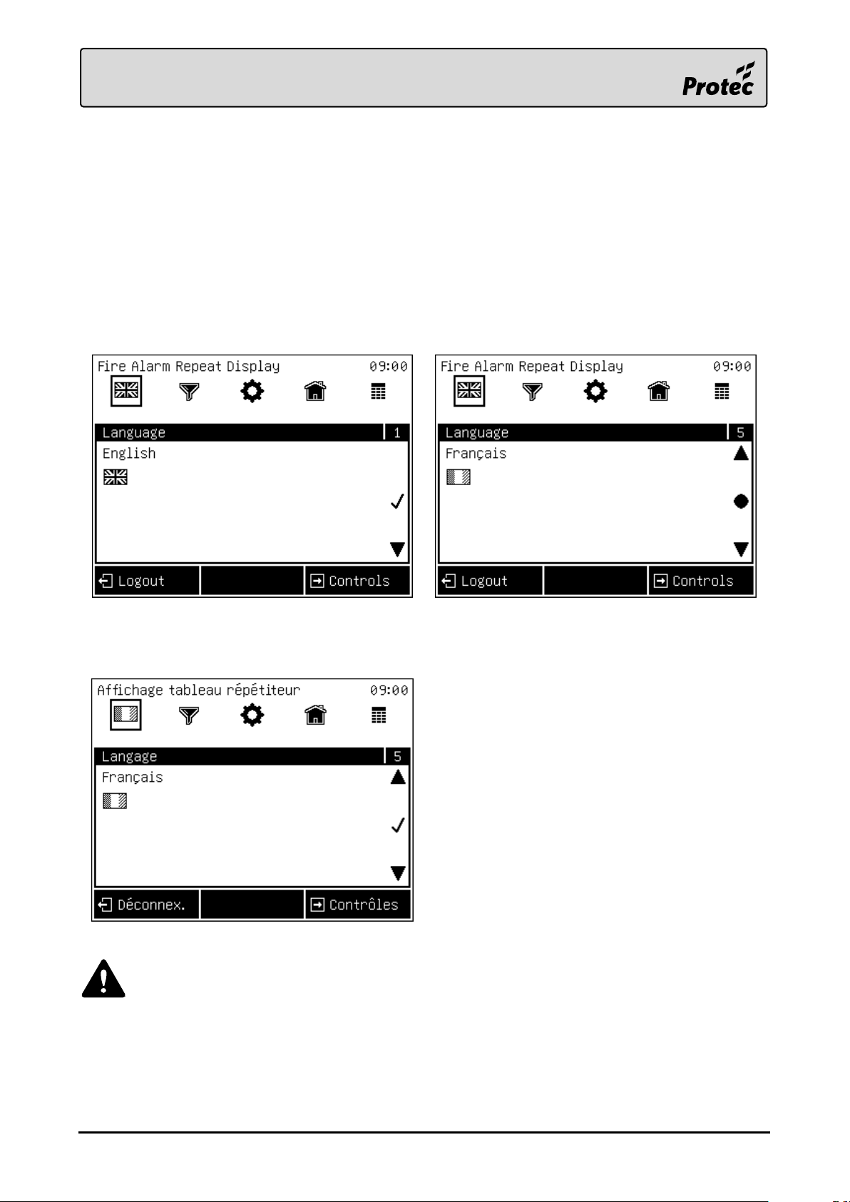
8.2 Change the GUI Language
It is possible to change the GUI Language on the device through the engineer menu.
A. Starting from the beginning of the engineer menu, ‘Language’.
B. Use the ‘Up’▲ and ‘Down’▼ buttons to scroll through the available languages.
C. Press the ‘Select’● button to accept the currently displayed language. The symbol will change
to a tick symbol to show the language is currently selected.
D. Note: The device will save the new language setting upon exiting the engineer menu.
Note if the selected language is not available in the current device firmware the language will
return to the previous setting.
RDM0012 Issue 1 AA Page 31 of 35 © Protec Fire Detection PLC 2017
Page 32
A
B
C
D
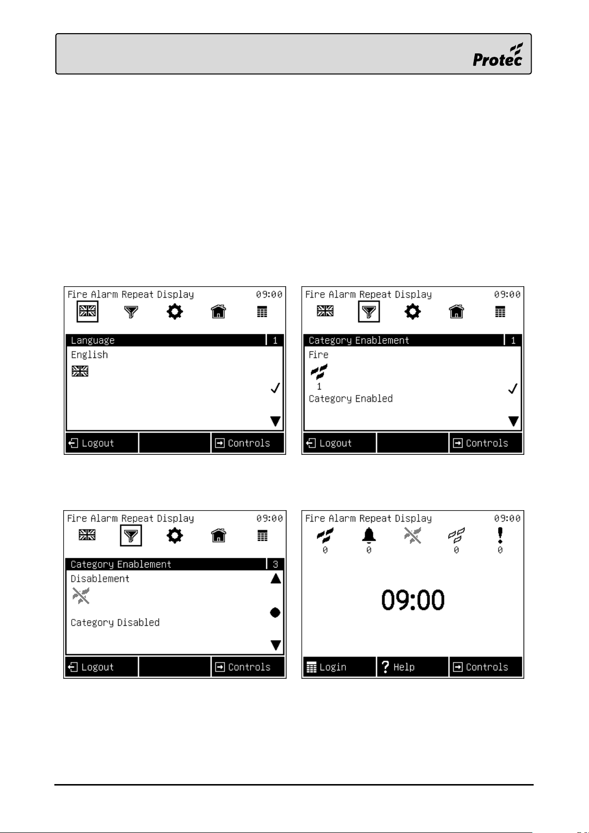
8.3 Event Category Enablement
It is possible to prevent certain event categories from displaying on the device. When a category is
disabled the device will not indicate or display any new events of that type.
A. Starting from the beginning of the engineer menu, ‘Language’.
B. Pressing the ‘Next’► button until the ‘Category Enablement’ menu is shown.
C. Use the ‘Up’▲ and ‘Down’▼ buttons to scroll through the event categories. Then press
‘Select’● the enable or disable them.
D. Back in access level 1, the icons of disabled categories will be greyed out to represent the
setting.
E. Note: The device will save the new setting upon exiting the engineer menu.
RDM0012 Issue 1 AA Page 32 of 35 © Protec Fire Detection PLC 2017
Page 33
8.4 Default Access Codes
The 6000/LOOP/REPEATER is shipped with the following default access codes.
Default level 2 access code: 1 8 4 8
Default level 3 access code: 3 1 4 4
It is strongly recommended that these access codes are changed upon the installation of the
device. Either through the Stand Alone Repeater Programmer or the access level 3 menu on
the device itself.
RDM0012 Issue 1 AA Page 33 of 35 © Protec Fire Detection PLC 2017
Page 34
This way up
9.0 Appendix 1 - Installation Template
All dimensions in mm.
RDM0012 Issue 1 AA Page 34 of 35 © Protec Fire Detection PLC 2017
Page 35

Designed and Manufactured in the United Kingdom
RDM0012 Issue 1 AA Page 35 of 35 © Protec Fire Detection PLC 2017
 Loading...