

Page 1

93-310-10 Issue 4 Rev 5 Page 1 of 88 Copyright Protec Fire Detection PLC
6400 OPERATING MANUAL
IIS
S
S
S
U
U
E
E
S
S
ISSUE DATE RELEASED DETAILS OF CHANGE AUTHOR
4 Rev 2 September 2004 Changes for 4000 series. DB
4 Rev 3 April 2005 Screen shots updated and other minor changes K.Z.
4 Rev 4 September 2006
Updated section 4.1 (Advanced Options)
Updated section 6.1 (Fire Alarm Count)
Updated section 8.2 (DSZ & DSG status)
Updated section 10.1 (View / Edit)
Updated section 13.3 (Low & high sensitivity)
Added section 26 (Loop LCD Panel)
Several screen shots updated
PD
4 Rev 5 April 2007
Removed section 1.5
Added section 8.5.2 (Fault Link)
Changed ‘Device Disabled’ led to ‘Disablement’
Added section 8.7 (Output Delay Disablement)
Several screen shots updated
PD
Notes
1) This manual covers 4400, 5400 and 6400 systems. The differences are described in the
appropriate sections.
2) This manual covers Fire and General Alarm systems. The differences are described in the
appropriate sections.
Page 2

93-310-10 Issue 4 Rev 5 Page 2 of 88 Copyright Protec Fire Detection PLC
6400 OPERATING MANUAL
C
C
O
O
N
N
T
T
E
E
N
N
T
T
S
S
OOVVEERRVVIIEEW
W....................................................................................................................................................................5
1.1 6400 NETWORK OVERVIEW.......................................................................................................................... 5
1.2 6400 NODE DESCRIPTIONS............................................................................................................................ 6
1.3 DCN NODE ........................................................................................................................................................ 6
1.4 LPN NODE ......................................................................................................................................................... 6
DDCCNN FFUUNNCCTTIIOONNS
S......................................................................................................................................................... 7
2.1 NORMAL DISPLAY.......................................................................................................................................... 7
2.2 VIEWING FIRE / ALARM EVENTS ..............................................................................................................8
2.2.1 MULTIPLE DEVICES IN ALARM ............................................................................................................9
2.2.2 GENERAL ALARM ....................................................................................................................................9
2.3 PRINTING FIRE EVENTS......................................................................................................................... 10
2.4 SILENCING FIRE EVENTS ...................................................................................................................... 10
2.5 SOUND ALARMS............................................................................................................................................11
2.6 RESETTING FIRE EVENTS ......................................................................................................................... 11
2.7 DISPLAY OF FAULT EVENTS...................................................................................................................11
2.7.1 VIEWING FAULT EVENT DETAILS. .................................................................................................12
2.7.2 MUTING THE ‘FAULT’ BUZZER...........................................................................................................12
2.8 DISPLAY OF DISABLEMENTS................................................................................................................... 13
2.8.1 VIEWING DISABLEMENT DETAILS..................................................................................................14
2.8.2 MUTING THE ‘DISABLEMENT’ BUZZER ........................................................................................14
RROOUUTTIINNEE AATTTTEENNTTIIOON
N.............................................................................................................................................. 15
3.1 RESPONSIBLE USER.......................................................................................................................................15
3.2 ROUTINE TESTS..............................................................................................................................................15
UUSSEERR MMEENNUU AACCCCEESSS
S................................................................................................................................................16
4.1 MENU ACCESS ...............................................................................................................................................16
SSEETT TTIIMMEE && DDAATTE
E ..................................................................................................................................................... 18
5.1 SET TIME & DATE. ........................................................................................................................................18
5.2 SETTING THE DATE......................................................................................................................................19
5.3 SETTING THE TIME.......................................................................................................................................21
DDIISSPPLLAAYY EEVVEENNTTS
S ......................................................................................................................................................22
6.1 DISPLAY EVENTS.........................................................................................................................................22
6.2 DISPLAY PAST FIRES..................................................................................................................................23
6.3 DISPLAY PAST FAULTS.............................................................................................................................. 24
PPRRIINNTTEERR MMEENNU
U.......................................................................................................................................................... 25
7.1 PRINTER MENU............................................................................................................................................. 25
7.2 PRINT CURRENT FAULTS.......................................................................................................................... 26
7.3 PRINT CURRENT DISABLEMENTS...........................................................................................................27
7.4 PRINT PAST EVENTS ..................................................................................................................................28
7.4.1 PRINT PAST FIRES / ALARMS ............................................................................................................29
7.4.2 PRINT PAST FAULTS............................................................................................................................29
7.4.3 PRINT PAST DISABLEMENTS ............................................................................................................30
7.4.4 PRINT PAST OTHER EVENTS............................................................................................................30
7.5 PRINT ANALOGUE VALUES...................................................................................................................... 31
7.6 PRINT ADDRESS S/N ..................................................................................................................................... 32
7.7 PRINT HIGH ANALOGUE VALUES...........................................................................................................33
7.8 CANCEL PRINTING.......................................................................................................................................33
DDIISSAABBLLEEMMEENNTT MMEENNU
U..............................................................................................................................................34
8.1 DISABLEMENT MENU .................................................................................................................................34
8.2 DEVICE DISABLE / NORMALISE................................................................................................................35
8.3 DISABLEMENTS TO VIEW......................................................................................................................... 39
8.4 ZONE DISABLE / NORMALISE.....................................................................................................................41
8.5 OUTPUT DISABLEMENT MENU ................................................................................................................43
Page 3

93-310-10 Issue 4 Rev 5 Page 3 of 88 Copyright Protec Fire Detection PLC
6400 OPERATING MANUAL
8.5.1 DISABLE / ENABLE FIRE LINK ........................................................................................................ 43
8.5.2 DISABLE / ENABLE FAULT LINK....................................................................................................44
8.5.3 DISABLE / ENABLE ALARM OUTPUTS.............................................................................................. 45
8.5.4 DISABLE / ENABLE CONTROL OUTPUTS.......................................................................................... 46
8.6 CHANGE TO ADDRESS DISABLE .............................................................................................................. 47
8.7 OUTPUT DELAY DISABLEMENT ............................................................................................................... 48
TTEESSTT OOPPTTIIOONNS
S........................................................................................................................................................... 50
9.1 TEST OPTIONS............................................................................................................................................... 50
9.2 LAMP TEST.................................................................................................................................................... 50
9.3 VIEW ANALOGUE VALUES....................................................................................................................... 51
9.4 WALK TEST MENU ...................................................................................................................................... 53
9.4.1 WALK TEST ZONE................................................................................................................................... 54
9.5 RVAV (Remote Visual Address Verification) ..................................................................................................56
9.5.1 RVAV SINGLE ......................................................................................................................................... 56
9.5.2 RVAV DESCRIPTION.............................................................................................................................. 58
TTEEXXTT EEDDIITTOOR
R............................................................................................................................................................. 59
10.1 TEXT EDITOR.............................................................................................................................................. 59
10.2 EDIT LOOP DEVICE TEXT ......................................................................................................................... 60
CCLLEEAARR SSYYSSTTEEMM FFAAUULLT
T........................................................................................................................................... 63
11.1 CLEAR SYSTEM FAULT .......................................................................................................................... 63
AADDVVAANNCCEEDD OOPPTTIIOONNS
S............................................................................................................................................... 64
12.1 ADVANCED OPTIONS................................................................................................................................. 64
12.2 EXCHANGE DEVICES................................................................................................................................. 65
12.3 ACCESS CODES........................................................................................................................................... 70
RREEFFEERREENNCCE
E................................................................................................................................................................ 72
13.1 THRESHOLD LEVELS FOR 6000 SERIES ANALOGUE DEVICES.......................................................... 72
13.2 THRESHOLD LEVELS FOR 6000 SERIES DIGITAL DEVICES................................................................ 72
13.3 THRESHOLD LEVELS FOR 5000 SERIES DEVICES.................................................................................. 73
13.4 THRESHOLD LEVELS FOR 4000 SERIES DEVICES.................................................................................. 73
13.5 OPERATING MENU FLOWCHART.............................................................................................................. 74
NNEETTWWOORRKK RREEPPEEAATT PPAANNEELLS
S................................................................................................................................... 75
14.1 NETWORK LCD PANEL - (No network controls)........................................................................................ 75
14.2 RDN PANEL – (With network controls) ........................................................................................................ 75
NNEETTWWOORRKK LLCCDD DDIISSPPLLAAY
Y........................................................................................................................................ 76
15.1 NETWORK LCD DISPLAY.......................................................................................................................... 76
FFUUNNCCTTIIOONN BBUUTTTTOONNS
S............................................................................................................................................... 77
16.1 - FUNCTION BUTTONS................................................................................................................................ 77
MMEENNUU OOPPTTIIOONNS
S......................................................................................................................................................... 78
17.1 MENU OPTIONS........................................................................................................................................... 78
17.2 MENU VIEWING INSTRUCTIONS............................................................................................................. 78
VVIIEEWWIINNGG FFIIRREE EEVVEENNTTS
S........................................................................................................................................... 79
18.1 VIEWING FIRES / ALARMS........................................................................................................................ 79
18.2 VIEWING MULTIPLE FIRE / ALARMS ................................................................................................... 79
SSIILLEENNCCIINNGG FFIIRREE EEVVEENNTTS
S........................................................................................................................................ 81
19.1 SILENCING FIRE EVENTS.......................................................................................................................... 81
RREESSEETTTTIINNGG AA FFIIRREE EEVVEENNT
T ..................................................................................................................................... 82
20.1 RESETTING A FIRE EVENT ....................................................................................................................... 82
VVIIEEWW CCUURRRREENNTT FFAAUULLTTS
S......................................................................................................................................... 83
21.1 VIEW CURRENT FAULTS........................................................................................................................... 83
VVIIEEWW CCUURRRREENNTT DDIISSAABBLLEEMMEENNTTS
S ......................................................................................................................... 84
22.1 VIEW CURRENT DISABLEMENTS ........................................................................................................... 84
PPRRIINNTTIINNG
G.................................................................................................................................................................... 85
23.1 PRINTING - RDN Only ................................................................................................................................ 85
LLAAMMPPTTEESST
T..................................................................................................................................................................86
24.1 LAMPTEST.................................................................................................................................................... 86
AABBOORRTT PPRRIINNTTOOUUT
T .................................................................................................................................................... 86
25.1 ABORT PRINTOUT ...................................................................................................................................... 86
Page 4

93-310-10 Issue 4 Rev 5 Page 4 of 88 Copyright Protec Fire Detection PLC
6400 OPERATING MANUAL
LLOOOOPP RREEPPEEAATT PPAANNEEL
L............................................................................................................................................... 87
LOOP LCD PANEL..................................................................................................................................................87
26.1 NORMAL DISPLAY....................................................................................................................................87
26.2 FAULT DISPLAY ........................................................................................................................................88
26.3 FIRE DISPLAY............................................................................................................................................. 88
26.4 LAMP TEST .................................................................................................................................................88
Page 5
93-310-10 Issue 4 Rev 5 Page 5 of 88 Copyright Protec Fire Detection PLC
6400 OPERATING MANUAL
O
O
V
V
E
E
R
R
V
VII
E
E
W
W
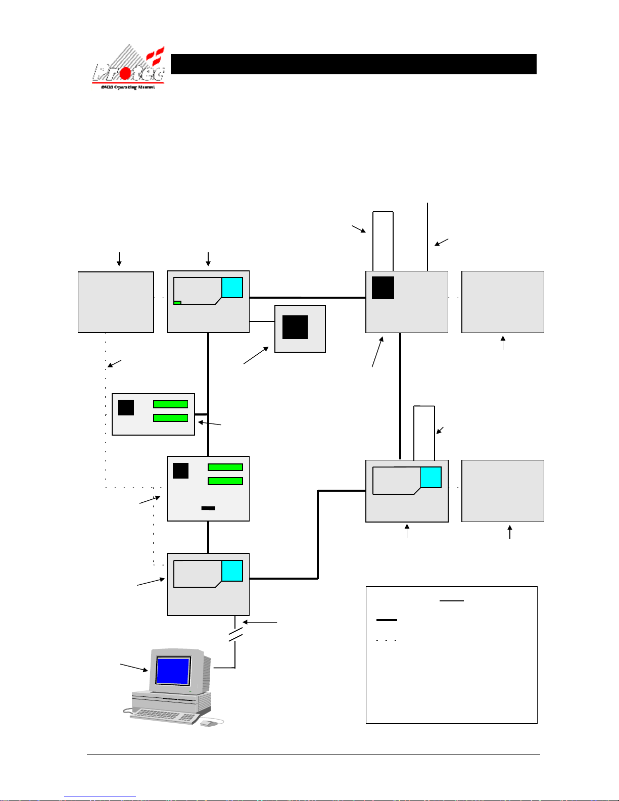
1.1 6400 NETWORK OVERVIEW
6400 PSU
To supply LPN
6400 PSU
To supply DCN
6400 DCN node
Has FULL display and control of
the network
6400 LPN
can drive up to 4 loops of
127 devices
(508 devices)
in total
6400 LPN
can drive up to
8 sounder circuits
6 aux contacts
6400 LPN node
Drives field wiring
NO control of network
KEY
Secure network (RS485)
24 volt supply from PSU to node.
LPN = Loop processing Node
DCN = Display control Node.
RDN = Repeat display Node
LCD = Network LCD repeater.
PSU = Power supply unit.
6400 DCN & LPN
Drives field wiring & has FULL
control of the network
6400 LPN
can drive up to 4 loops of 127
devices (508 devices) in total, 8
sounder circuits and 6 aux contacts
6400 PSU
To supply LPN
6400 RDN Node
Has full LCD display
with (optional printer).
Limited control of the network
6400 Network LCD (Listen)
Has full LCD display. NO printer
and NO control of the network.
Can be a spur off the network
24 volt supply to LCDs
can be taken from the
node PSU or a separate
PSU can be installed.
6400 DCN node
Has FULL display and control
of the network
2 RS232 Ports
used to connect a PC to
program the network and
operate a ‘graphics’, ‘pager’
or ‘BMS’ system.
PC or Lap-top
Can be connected to
any 6400 DCN on the
network
Zone expansion if greater
than 100 zones
Page 6
93-310-10 Issue 4 Rev 5 Page 6 of 88 Copyright Protec Fire Detection PLC
6400 OPERATING MANUAL
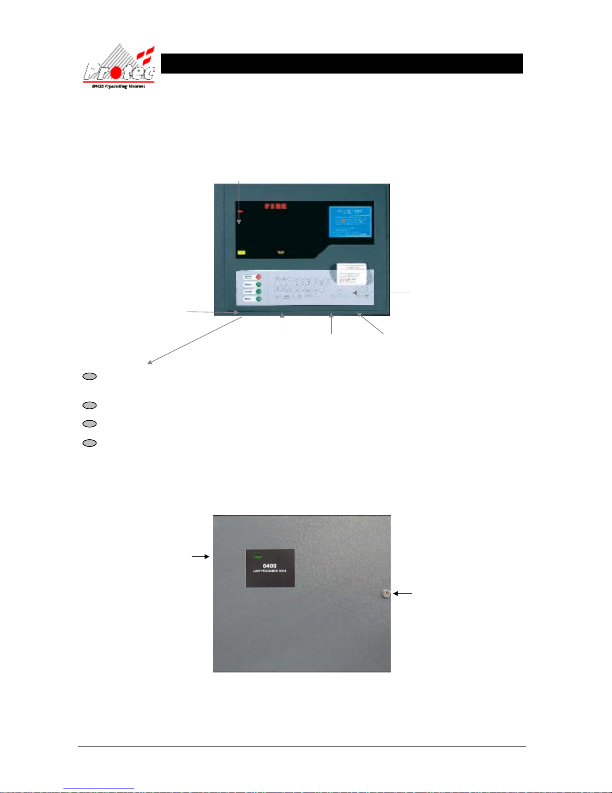
FIGURE 2 - Loop Processing Node (LPN)
Status LEDs
Door Lock
Printer Output
Control Buttons
1.2 6400 NODE DESCRIPTIONS
1.3 DCN NODE
LED Display LCD Display
QWERTY Keypad Arrow keys Numeric Keypad
SOUND ALARMS Pressing this button will operate ‘Alarm outputs’ on the network as programmed when the system was
commissioned.
SILENCE Pressing this button will Silence ALL ‘Alarm outputs’ on the network.
ACCEPT Pressing this button will accept any fire / fault events , and mute the fault buzzer.
RESET Pressing this button will reset ALL fire indications , and release any ‘Control outputs’ .
1.4 LPN NODE
FIGURE 1
Page 7
93-310-10 Issue 4 Rev 5 Page 7 of 88 Copyright Protec Fire Detection PLC
6400 OPERATING MANUAL
D
D
C
C
N
N
F
F
U
U
N
N
C
C
T
TII
O
O
N
N
S
S
2.1 NORMAL DISPLAY
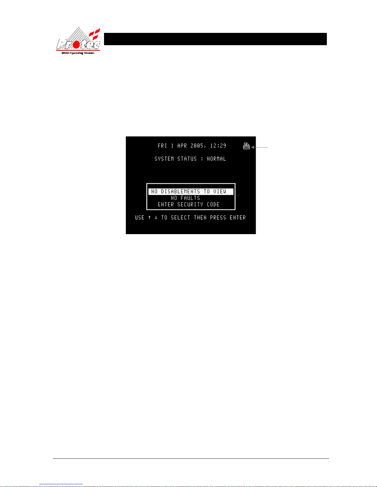
The following screen will be displayed when the system is in a ‘Normal’ condition (ie no
fires, faults or disablements) :-
• Logo : If there are no faults or disablements present then the box and highlight bar shown above
are replaced by the logo. Pressing ‘0’ or ‘Esc’ removes the logo.
Print Pending Icon
(
see section 2.3)
Page 8
93-310-10 Issue 4 Rev 5 Page 8 of 88 Copyright Protec Fire Detection PLC
6400 OPERATING MANUAL
2.2 VIEWING FIRE / ALARM EVENTS
FIRE SIGNAL
On hearing the ‘FIRE ALARM’ signal :a) Evacuate the premises IMMEDIATELY.
b) Send for the fire brigade.
c) DO NOT re-enter the premises until authorised by the fire brigade.
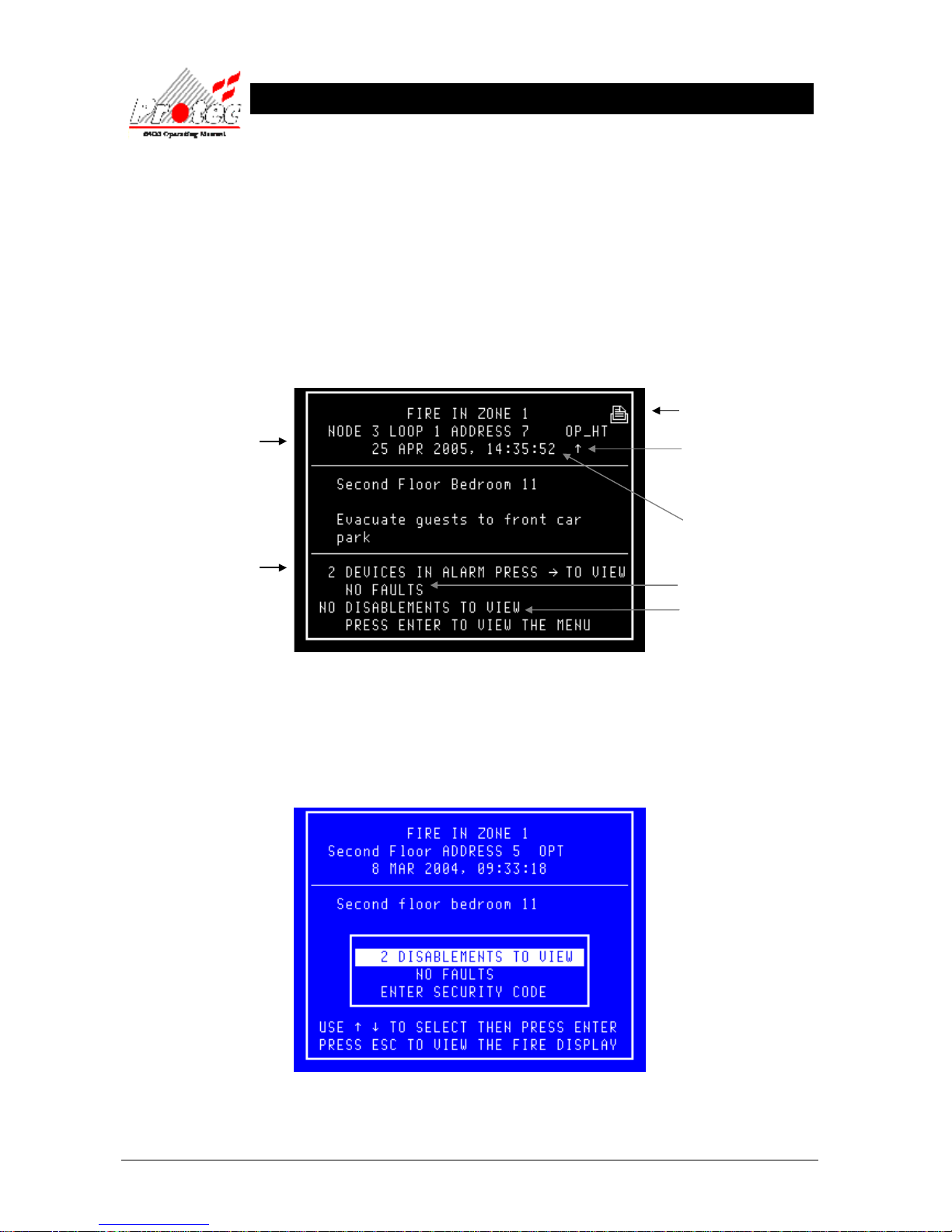
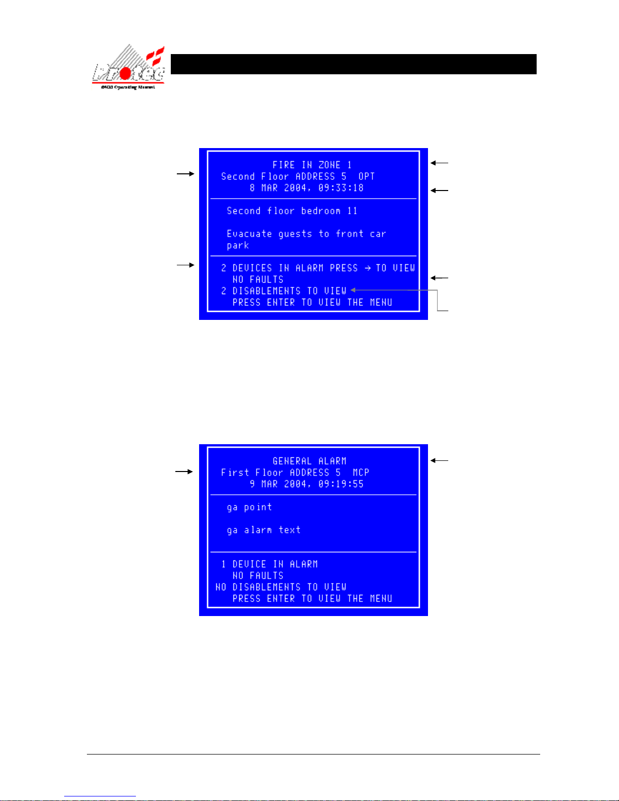
In the event of a fire activation occurring, the panel’s audible buzzer will fast pip. The ‘FIRE‘ lamp will illuminate
constantly and the ‘ZONE’ location lamp will illuminate intermittently. The panel will also display the location details
on the LCD display as follows :-
• Accept : Pressing the ‘Accept’ button will mute the panel buzzer. The buzzer will resound upon a further
activation. If a search time has been set up when the system was installed then pressing this button
will also start the search time.
• Menus : Pressing the ‘ENTER’ button will display the normal menu options, which will allow access to the
‘Main menu‘ or allow the display of any fault or disablements currently on the system as shown
below :-
• Exiting option : To return to the ‘FIRE’ display, press the ‘Esc’ key
Displays the Node /
Loop / address and type
of the device in alarm
Note - If text has been
assigned to the node,
then the text will be
displayed rather than the
node & loop No
Displays the ‘Zone’
number in which the fire
has occurred
Displays the date &
time of the activation
Displays the number of
fault events currently on
the system
Displays the number of
disablements currently
on the system
Displays the number
of Devices which are
currently in an alarm
condition
The arrow indicates the
sensor that has generated
the fire signal.
Page 9
93-310-10 Issue 4 Rev 5 Page 9 of 88 Copyright Protec Fire Detection PLC
6400 OPERATING MANUAL
2.2.1 MULTIPLE DEVICES IN ALARM
In the event of more than one device producing a fire condition, the display will show the following :-
Pressing the → key will scroll the display to show the description of each device in an alarm condition.
2.2.2 GENERAL ALARM
The 6400 system is also used to display General Alarms. If the system is a General Alarm one then the ‘ALARM’ led
and the zone led will illuminate but if the system is a Fire Alarm one then these two leds will not illuminate to prevent
confusion with a fire signal. The display of a general alarm is shown below :-
Displays the Node /
Loop / address and type
of the device in alarm
Note - If text has been
assigned to the node,
then the text will be
displayed rather than the
node & loop No
Displays the ‘Zone’
number in which the fire
has occurred
Displays the date &
time of the activation
Displays the number of
fault events currently on
the system
Displays the number of
disablements currently
on the system
Displays the number
of Devices which are
currently in an alarm
condition
General Alarm
Displays the Node /
Loop / address and type
of the device in alarm
Note - If text has been
assigned to the node,
then the text will be
displayed rather than
the node & loop No
Page 10
93-310-10 Issue 4 Rev 5 Page 10 of 88 Copyright Protec Fire Detection PLC
6400 OPERATING MANUAL
2.3 PRINTING FIRE EVENTS
The 6400 control panel will NOT print ‘Fire’ events automatically, they are printed on demand. If the panel has any
events pending, the ‘Print Pending Icon’ will be shown on the top right corner of the LCD Display (see section 2.1).
To print these events press and hold the ‘ Fn’ key and then press the ‘p’ key on the QWERTY keypad. This will print
any fire events which have occurred in the following format :-
On the completion of printing all the events, the ‘PRINT’ Icon will extinguish and the printer will stop printing.
To cancel printing at any time, press and hold the ‘Fn’ key and then press the ‘c’ key on the QWERTY keypad.
This will stop the print-out.
2.4 SILENCING FIRE EVENTS
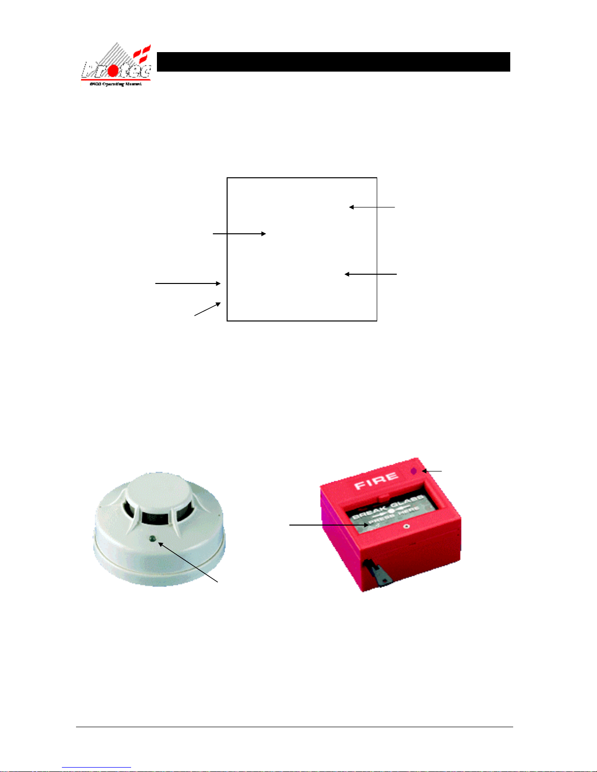
Pressing the ‘SILENCE’ key after any FIRE event will cause the ‘ALARMS SILENCED’ lamp to illuminate and the
alarms to silence. The fast pip is an indication that the external alarm outputs are activated. DO NOT at this stage
attempt to ‘RESET’ the system until the cause of the fire has been established.
SMOKE / HEAT SENSOR BREAK GLASS UNIT
The Alarms can be resounded at any time by pressing the ‘Sound alarms’ button (refer to section 2.5 for details).
Manual call points must be physically reset. Automatic sensors must be visually checked to determine the operated
sensor. Further fire signals from other addresses will automatically re-sound the alarms (according to the cause &
effects of the site).
Location of device
The Date & time the ‘List of
pending fires’ was printed
The fire ZONE where the device has
activated
Up to 60 characters of location text &
up to 60 characters of alarm text
(optional)
The time & date the fire event occurred
****************************
List of pending fires / alarms
22 Jan 2007, 10:05:22
****************************
Location text
Alarm text
Time 22 Jan 2007, 09:17:15
Fire in zone 1
Node 2 Loop
2 Address 14 Type
If the Red LED (Light) is
illuminated on the break
glass, the glass is most likely
to have been smashed.
If the Red LED (Light) is
illuminated constantly on the
smoke sensor, it means that
this device has activated.
Inspect the Glass for
breakage. If broken
replace glass.
Page 11
93-310-10 Issue 4 Rev 5 Page 11 of 88 Copyright Protec Fire Detection PLC
6400 OPERATING MANUAL
2.5 SOUND ALARMS
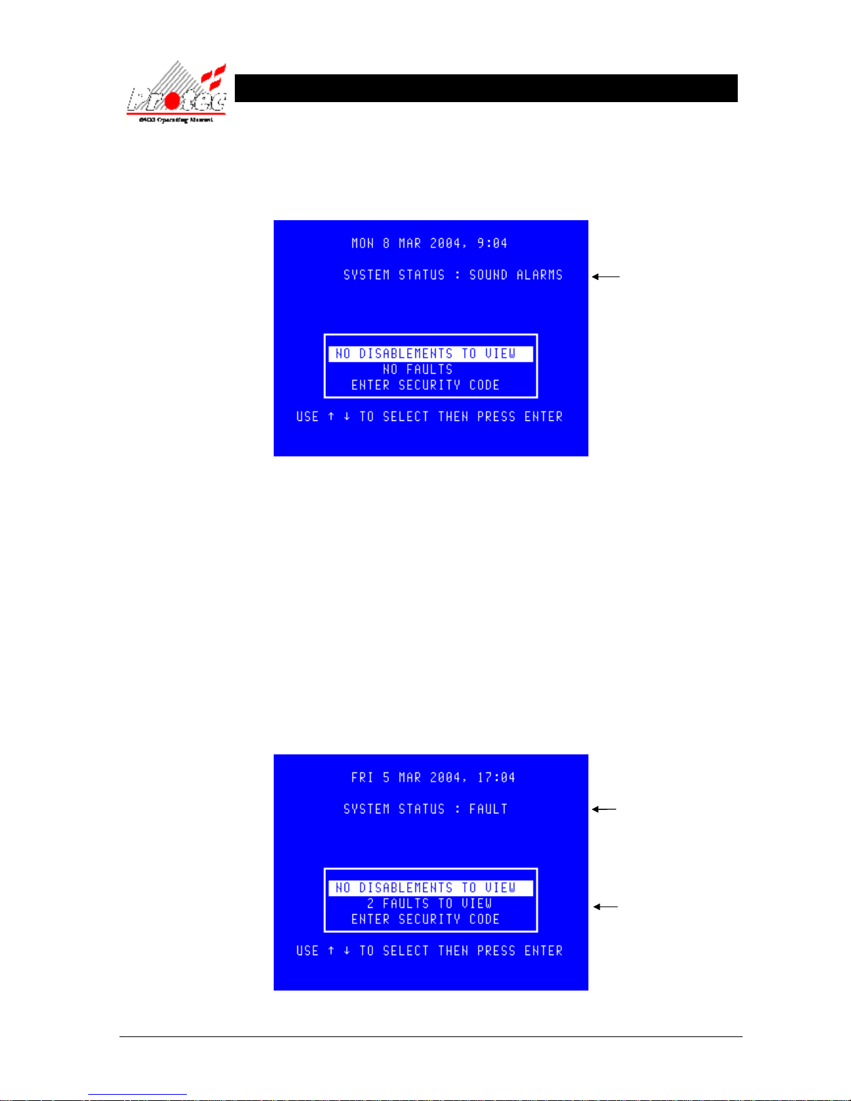
Pre-programmed Alarm Outputs may be sounded by pressing the ‘Sound alarms’ button (red).
This will illuminate the ‘Alarms On’ LED, the buzzer will fast pip and the screen will display the following :.
To silence the alarms, press the ‘Silence’ control button. This will extinguish the ‘Alarms On’ LED , stop the sounders
and mute the panel buzzer. The display will also return to ‘System status : Normal’.
2.6 RESETTING FIRE EVENTS
After ‘silencing alarms’ (Section 2.4) and establishing the cause of the fire :a) Press the ‘RESET’ button.
Any fire indications will be extinguished.
Any plant equipment (control outputs) will be reset.
The fire condition will re-start if an automatic detector or manual call point remain active.
2.7 DISPLAY OF FAULT EVENTS
In the event of a fault appearing on the system the panel buzzer will sound intermittently, and the ‘FAULT’ LED will
illuminate. The LCD will also display the number of faults to view, as shown below :-
Indicates the system is in a
fault status
Displays the number of
faults currently on the
system.
Indicates alarms are on
Page 12
93-310-10 Issue 4 Rev 5 Page 12 of 88 Copyright Protec Fire Detection PLC
6400 OPERATING MANUAL
2.7.1 VIEWING FAULT EVENT DETAILS.
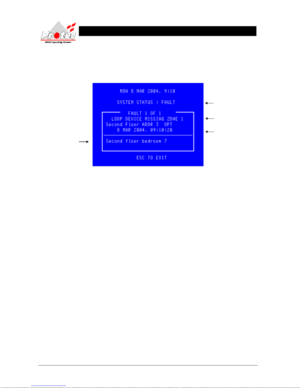
• Selecting option : To view the current fault events move the highlight bar using the ‘arrow keys’ onto the ‘X
faults to view’ (as shown in section 2.7 ), and then press the ‘ENTER’ button, this will then
prompt the following display indicating the current fault events on the system :-
• Other faults : Press ← or → to view other fault events.
• Exiting option : To EXIT ‘viewing the fault events’ press the ‘ESC’ button . This will return to the
normal screen options (see section 2.7).
2.7.2 MUTING THE ‘FAULT’ BUZZER
To mute the panel buzzer, press the ‘ACCEPT’ button. This will mute the panel buzzer. In the event of a further fault
occurring, the buzzer will resound and the ‘X faults to view’ will increment.
Indicates the system is in a
fault condition
Displays the fault description
Displays the date and time when
the fault event occurred
Displays the location text of
the fault (only displayed for
certain events)
Page 13
93-310-10 Issue 4 Rev 5 Page 13 of 88 Copyright Protec Fire Detection PLC
6400 OPERATING MANUAL
2.8 DISPLAY OF DISABLEMENTS
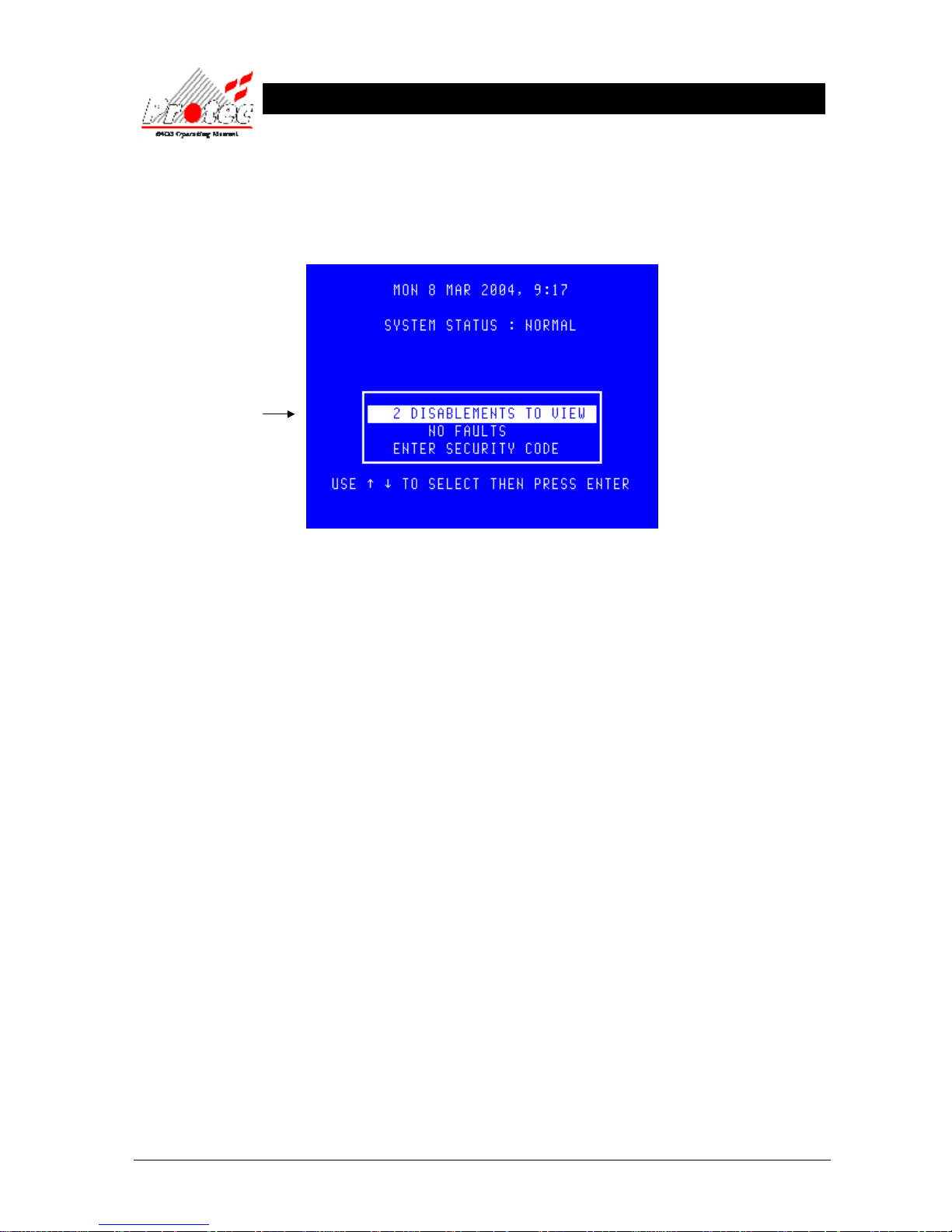
In the event of a device being disabled on the system the panel buzzer will sound intermittently, and the ‘Disablement’
LED will illuminate. The LCD will also display the number of disablements to view, as shown below :-
Displays the number of
disablements currently
on the system
Page 14
93-310-10 Issue 4 Rev 5 Page 14 of 88 Copyright Protec Fire Detection PLC
6400 OPERATING MANUAL
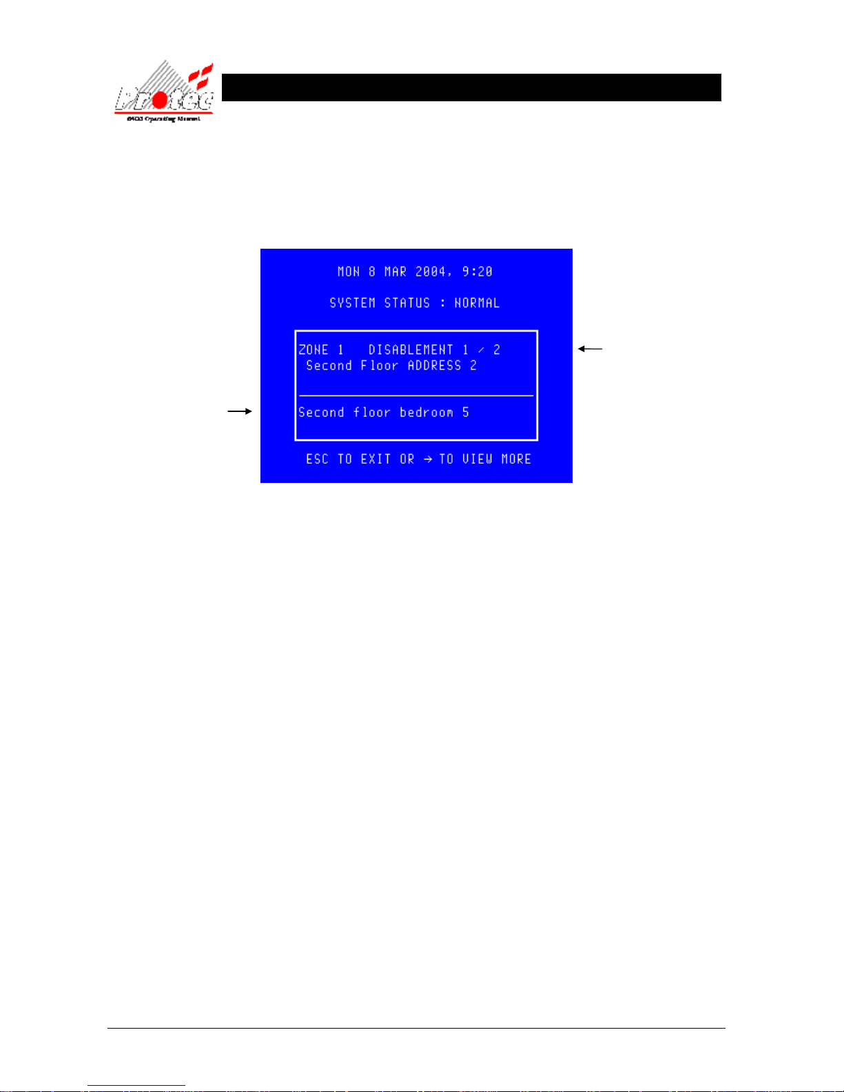
2.8.1 VIEWING DISABLEMENT DETAILS
• Selecting option : To view the current disablements move the highlight bar using the ‘arrow keys’ onto the
‘X disablements to view’ (as shown above), and then press the ‘ENTER’ button. This will
then prompt the following display indicating the current disablements on the system :-
• Other disablements :Use the → key to view any other disablements.
• Exiting option : To exit‘viewing the disablements’ press the ‘ESC’ button. This will return to the
normal screen options (see section 2.8)
2.8.2 MUTING THE ‘DISABLEMENT’ BUZZER
Press the ‘ACCEPT’ button to mute the panel buzzer. In the event of a further disablement the buzzer will resound
and the ‘X disablements to view’ will increment.
Displays the
disablement details
Displays the location text of
the disablement (does not
apply to some disablements)
Page 15

93-310-10 Issue 4 Rev 5 Page 15 of 88 Copyright Protec Fire Detection PLC
6400 OPERATING MANUAL
R
R
O
O
U
U
T
TII
N
N
E
E
A
A
T
T
T
T
E
E
N
N
T
TII
O
O
N
N
3.1 RESPONSIBLE USER
British standard BS5839-1: 2002, ‘Fire detection and fire alarm systems for buildings’ section 7 details the
responsibilities for the fire alarm user. These recommendations should be followed. For guidance on these
recommendations, please refer to the organisation that is responsible for servicing your fire alarm system.
These recommendations include :-
1. The fire alarm control and indicating equipment is checked at least once every 24 h to confirm that there are no
faults on the system.
2. The system log book is kept up to date and is available for inspection by any authorised person.
3. The routine testing is performed in accordance with the recommendations of BS5839-1 : 2002 section 6.
The above recommendations are only a selection taken from the standard. For a full list of
the recommendations refer to BS5839-1 : 2002.
3.2 ROUTINE TESTS
British standard BS5839-1: 2002, ‘Fire detection and fire alarm systems for buildings’ section 6 provides
recommendations for routine testing of the fire alarm by the user. These recommendations should be followed. For
guidance on these recommendations, please refer to the organisation that is responsible for servicing your fire alarm
system.
These recommendations include :-
a) Every week, a manual call point should be operated during normal working hours. It should be confirmed that
the control equipment is capable of processing a fire alarm signal and providing an output to fire alarm sounders,
and to ensure that the fire alarm signal is correctly received at any alarm receiving centre to which fire alarm
signals are transmitted.
b) In premises in which some employees only work during hours other than that at which the fire alarm system is
normally tested, an additional test(s) should be carried out at least once a month to ensure familiarity of these
employees with the fire alarm signal(s).
c) A different manual call point should be used at the time of the weekly test, so that all manual call points in the
building are tested in rotation over a prolonged period. There is no maximum limit for this period (eg in a system
with 150 manual call points, the user will test each manual call point every 150 weeks). The result of the weekly
test and the identity of the manual call point used should be recorded in the system log book.
The above recommendations are only a selection taken from the standard. For a full list of
the recommendations refer to BS5839-1 : 2002.
Page 16
93-310-10 Issue 4 Rev 5 Page 16 of 88 Copyright Protec Fire Detection PLC
6400 OPERATING MANUAL
U
U
S
S
E
E
R
R
M
M
E
E
N
N
U
U
A
A
C
C
C
C
E
E
S
S
S
S
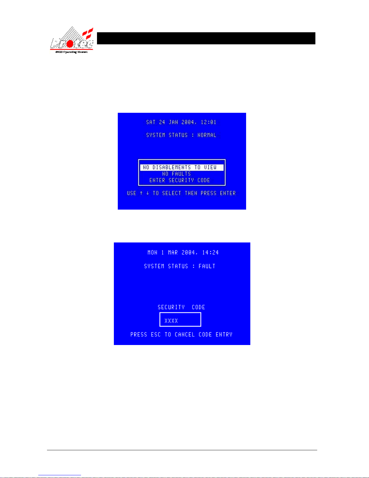
4.1 MENU ACCESS
Accessing the ‘User options’ will allow the operator to gain access into the ‘Main menu’ options.
Move the high-light bar using the arrow keys to ‘Enter security code’ (as shown) , then press the ‘ENTER’ key.
Enter the user access code, then press the ‘ENTER’ key. The LCD will display an ‘X’ for each number entered.
Page 17
93-310-10 Issue 4 Rev 5 Page 17 of 88 Copyright Protec Fire Detection PLC
6400 OPERATING MANUAL
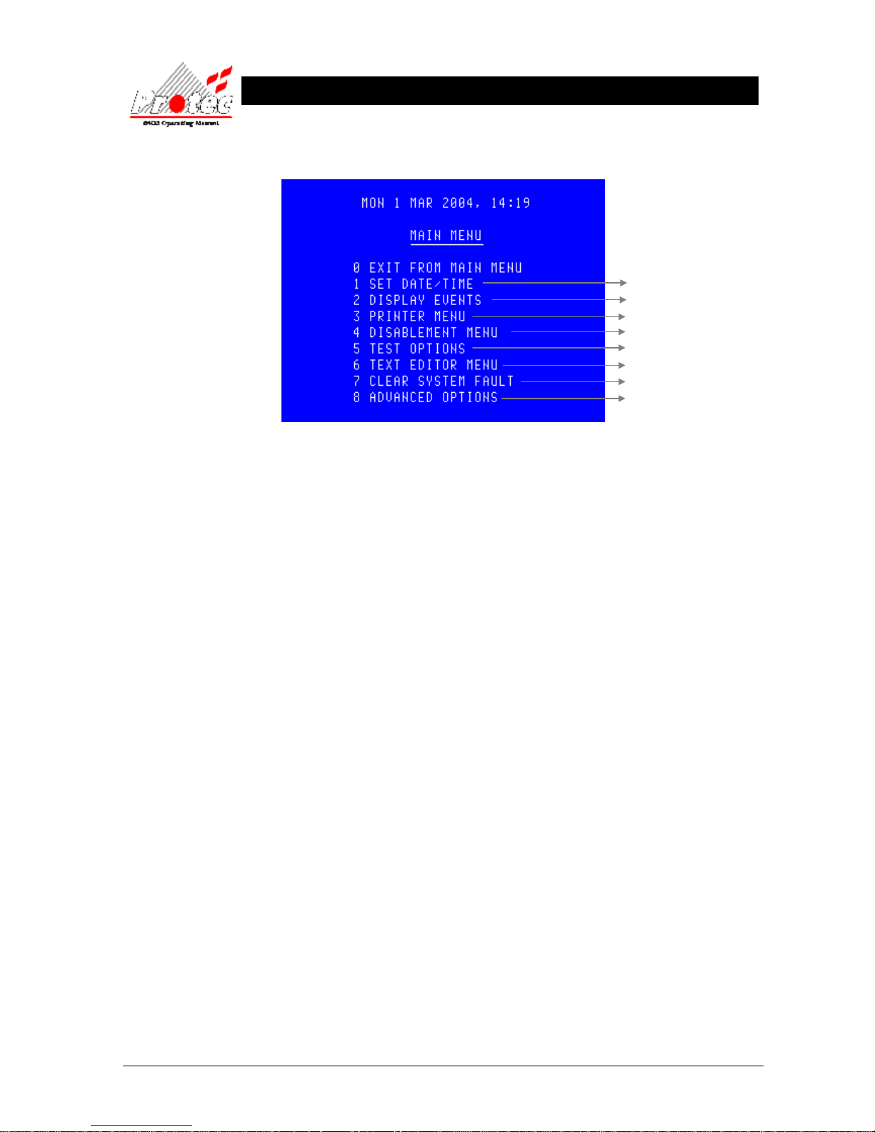
Once the code has been entered correctly, the following menu will be displayed :-
• Exiting menu : To EXIT the ‘Main menu’ options and return to the normal screen, press the ‘0’ or ‘ESC’
key.
• Advanced Options : This option is only available when either the ‘master’ user code is entered or the
‘Exchange’ user code. This latter code is available to users trained and authorised to make
changes to the system configuration.
For further details :-
Section 5
Section 6
Section 7
Section 8
Section 9
Section 10
Section 11
Section 12
Page 18
93-310-10 Issue 4 Rev 5 Page 18 of 88 Copyright Protec Fire Detection PLC
6400 OPERATING MANUAL
S
S
E
E
T
T
T
TII
M
M
E
E
&
&
D
D
A
A
T
T
E
E
5.1 SET TIME & DATE.
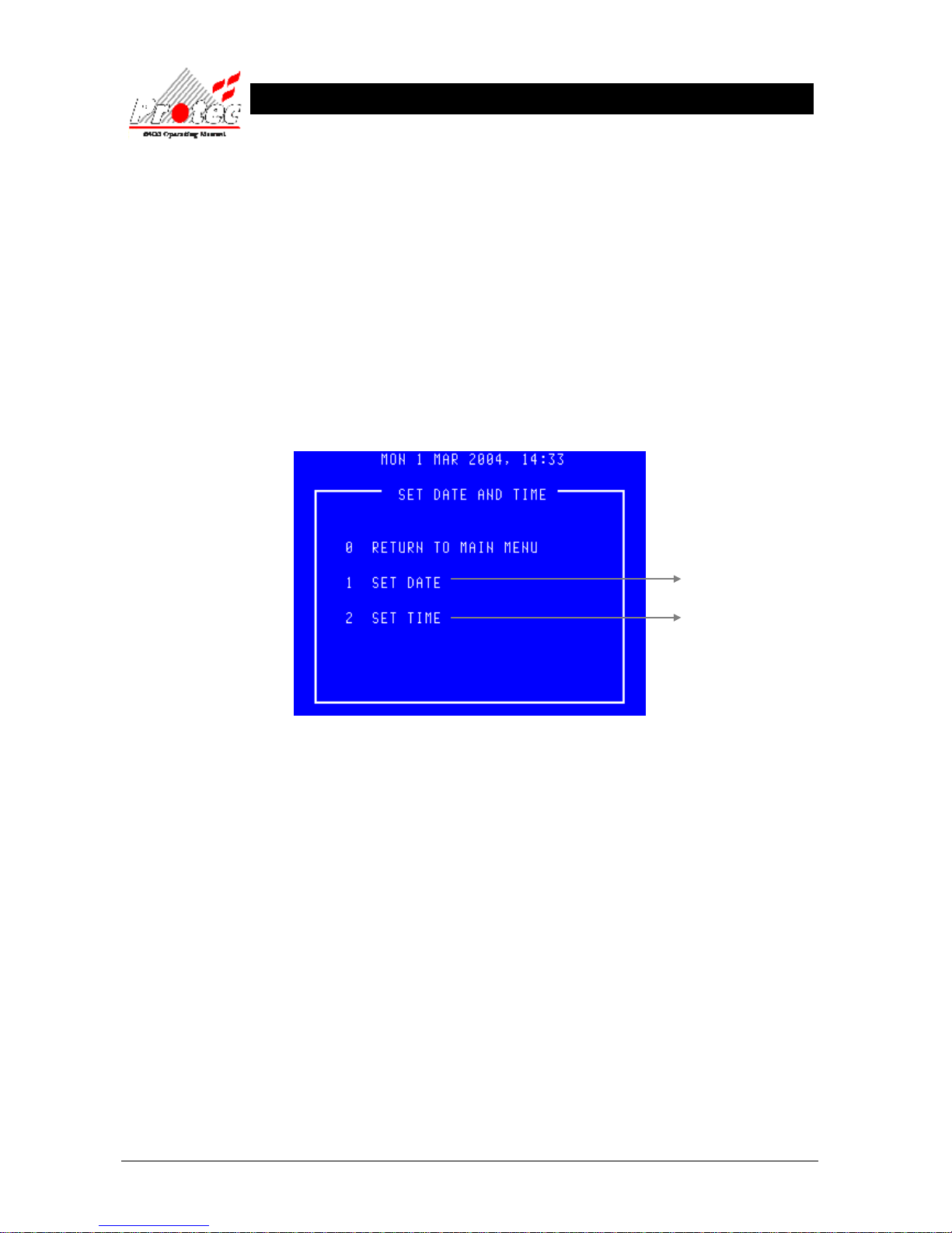
• Function : This option allows the ‘Time and date’ of the network to be altered.
Note - setting the ‘Time and date’ on any DCN will automatically update the ‘Time and
date’ on ALL the ‘Nodes’ on the network.
Leap years - The network will automatically compensate for ‘Leap years’.
British summer time - The network will NOT compensate for the changes in
‘British summer time’ and will have to be altered manually as defined in section 5.3.
• Selecting option : To select this option, press the number ‘1’ key from the ‘Main menu’ options.
Once selected, the LCD will display the following options :-
• Exiting option : To EXIT the ‘Set time & date’ option and return to the ‘Main menu’ options, press the ‘0’
key
For further details
Refer to section 5.2
Refer to section 5.3
Page 19
93-310-10 Issue 4 Rev 5 Page 19 of 88 Copyright Protec Fire Detection PLC
6400 OPERATING MANUAL
5.2 SETTING THE DATE
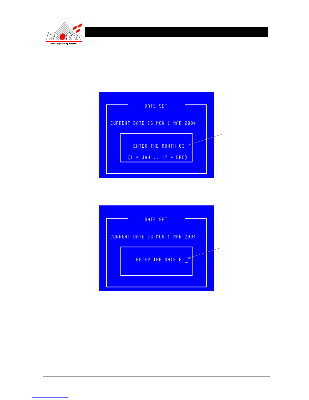
• Function : Allows the network ‘DATE’ to be altered.
• Selecting option : To alter the ‘MONTH’, press the number ‘1’ key from the ‘Set date and time’ option.
Once selected, the LCD will display the following :-
Once the correct ‘Month’ has been entered, press the ‘ENTER’ key. This will then prompt for the
correct ‘Date’ to be entered as follows :-
Use the ← key to delete the old Month.
Then type the new Month ( 1 ….. 12)
Use the ← key to delete the old date.
Then type the new date ( 1 ….. 31)
Page 20
93-310-10 Issue 4 Rev 5 Page 20 of 88 Copyright Protec Fire Detection PLC
6400 OPERATING MANUAL
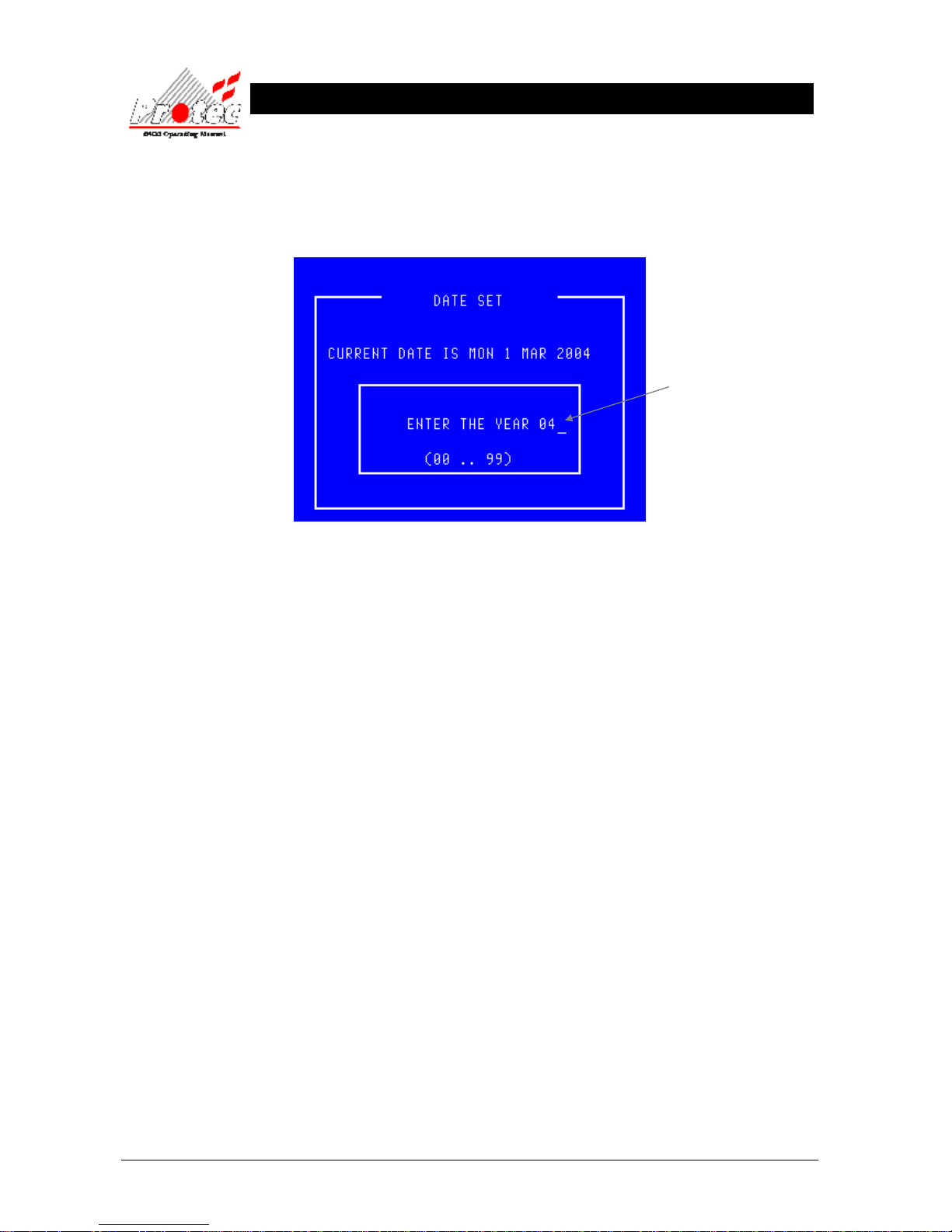
Once the correct ‘Date’ has been entered, press the ‘ENTER’ key. This will then prompt
for The correct ‘Year’ to be entered as follows:-
Once the correct ‘Year’ has been entered, press the ‘ENTER’ key. The display will then
return to the ‘Set date and Time’ menu option.
• Exiting option : The ‘Set date’ option can be Exited at any time by pressing the ‘ESC’ key. This will
return the screen to the ‘Set date and time’ menu options without updating the date.
Use the ← key to delete the old year
Then type the new year ( 00 ….. 99) .
Page 21
93-310-10 Issue 4 Rev 5 Page 21 of 88 Copyright Protec Fire Detection PLC
6400 OPERATING MANUAL
5.3 SETTING THE TIME
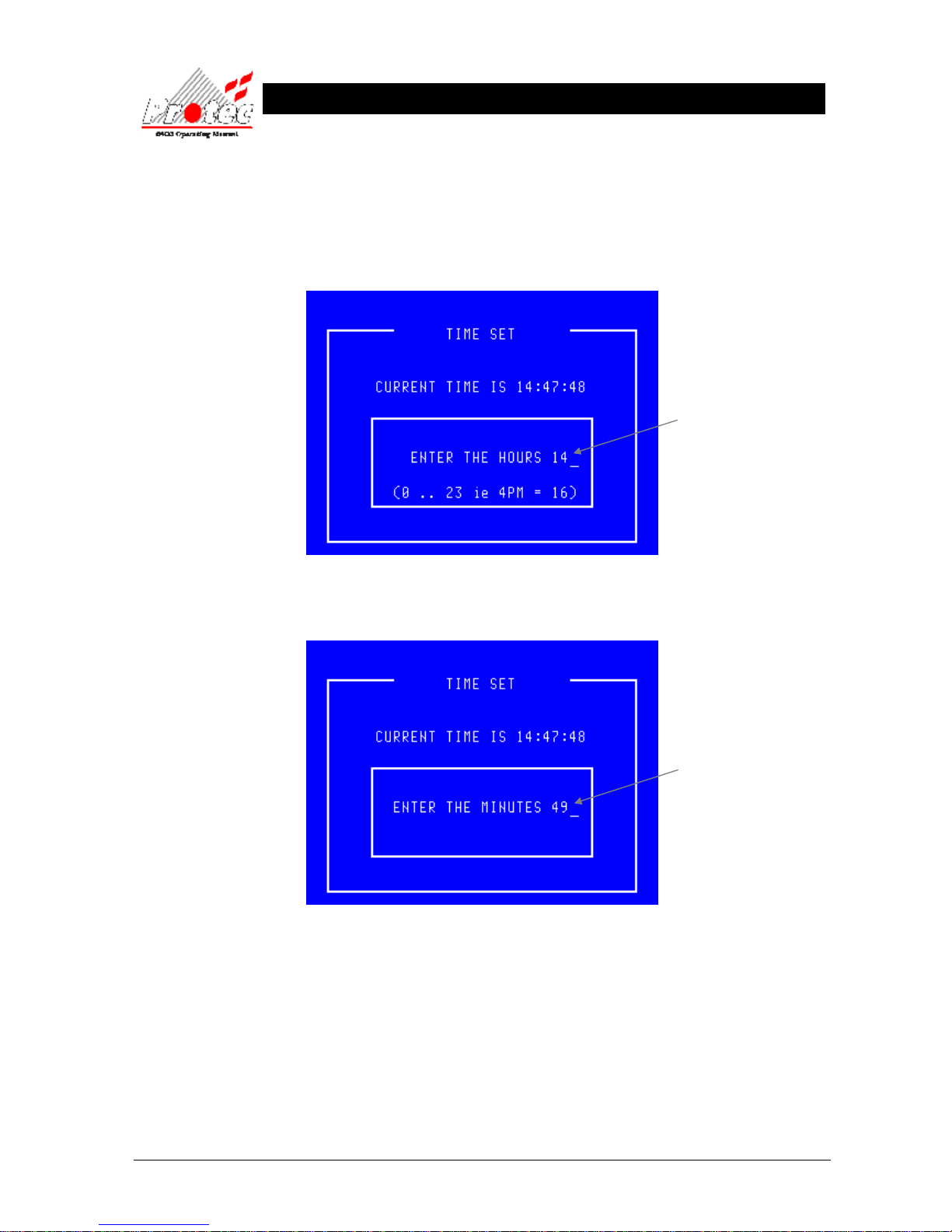
• Function : Allows the network ‘TIME’ to be altered.
• Selecting option : To alter the ‘TIME’, press the number ‘2’ key from the ‘Set date and time’ option.
Once selected, the LCD will display the following :-
Once the correct ‘Hour’ has been entered, press the ‘ENTER’ key. This will then prompt
for the correct ‘Minutes’ to be entered as follows :-
Once the correct ‘Minutes’ have been entered, press the ‘ENTER’ key. The display will
then return to the ‘Set date and time’ menu options.
• Exiting option : The ‘Set Time’ option can be exited at any time by pressing the ‘ESC’ key. This
will return the screen to the ‘Set date and time’ menu options without updating the time.
• Time Sync : In order to maintain time synchronisation between the nodes, every seven days the DCN
at which the time was last set transmits its current time to all other nodes.
Use the ← key to delete the old Hour.
Then type the new Hour ( 0 ….. 23)
Use the ← key to delete the old Minutes.
Then type the new Minutes ( 0 ….. 59)
Page 22
93-310-10 Issue 4 Rev 5 Page 22 of 88 Copyright Protec Fire Detection PLC
6400 OPERATING MANUAL
D
DII
S
S
P
P
L
L
A
A
Y
Y
E
E
V
V
E
E
N
N
T
T
S
S
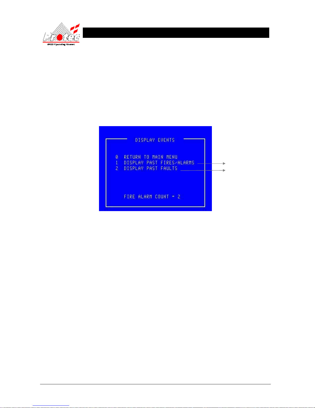
6.1 DISPLAY EVENTS.
• Function : This option allows the ‘Historic log’ of the network to be viewed.
This ‘Historic log’ will hold the last 1000 fire events and the last 1000 non-fire events.
• Selecting option : To select this option, press the number ‘2’ key from the ‘Main menu’ options.
Once selected, the LCD will display the following sub-menu options :-
• Exiting option : To EXIT the ‘Display’ options and return to the ‘Main menu’ options, press the ‘0’ key.
• Fire Alarm Count: The Fire Alarm Count is a record of the number of occasions that the panel has entered a
fire alarm condition. It is provided to comply with En54-2 : 1997 and assists the
responsible user to ensure that the system log book is up to date (refer to section 3.1).
For further details
Refer to section 6.2
Refer to section 6.3
Page 23
93-310-10 Issue 4 Rev 5 Page 23 of 88 Copyright Protec Fire Detection PLC
6400 OPERATING MANUAL
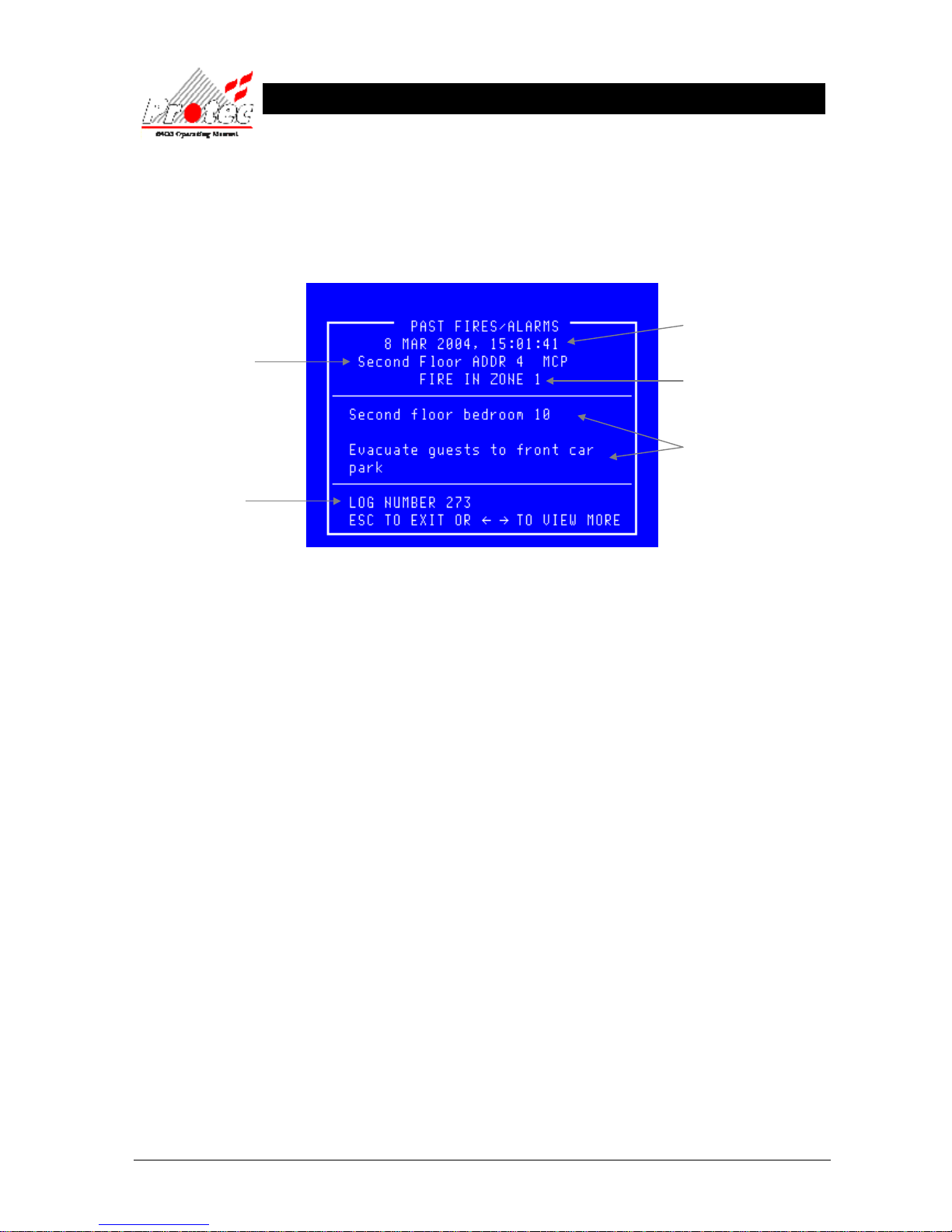
6.2 DISPLAY PAST FIRES.
• Function : This option allows the last 1000 events from the ‘Fire Historic log’ to be viewed.
• Selecting option : To select this option, press the number ‘1’ key from the ‘Display events’ menu options.
Once selected, the LCD will display the following information :-
• Viewing events : When the ‘Display past fires’ is selected, the most recent event is displayed first.
To view events further back in the ‘Historic log’ use the ← arrow key, each key press will
cycle one event at a time through the ‘Historic log’. Each time the ← arrow key is
pressed the ‘Log number’ on the bottom left hand side of the screen will change by on digit.
• Exiting option : To EXIT the ‘Display past fires’ options and return to the ‘Display’ sub-menu
options, press the ‘ESC’ key.
Displays the Node /
Loop / address and type
of the device in alarm
Note - If text has been
assigned to the node, then
the text will be displayed
rather than the node &
loop No
Displays the date & time of
the activation
Displays the ‘Zone’ number in
which the event occurred
Displays the ‘Location’ and ‘alarm’
text for the device that has alarmed.
This is an option and may NOT be
available in some cases.
Displays the log number
(0 - 999)
Page 24
93-310-10 Issue 4 Rev 5 Page 24 of 88 Copyright Protec Fire Detection PLC
6400 OPERATING MANUAL
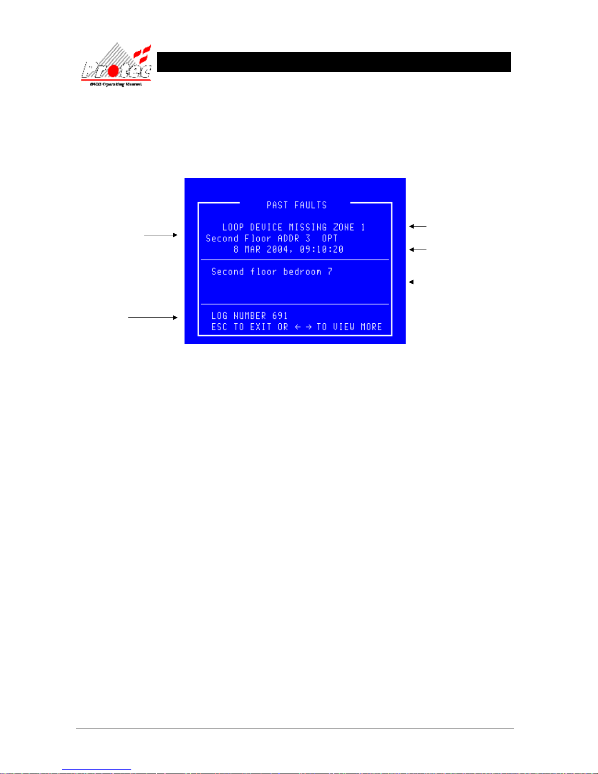
6.3 DISPLAY PAST FAULTS.
• Function : This option allows the last 1000 events from the ‘Faults Historic log’ to be viewed.
• Selecting option : To select this option, press the number ‘2’ key from the ‘Display events’ menu options.
Once selected, the LCD will display the following information :-
• Viewing events : When the ‘Display past faults’ is selected, the most recent event is displayed first.
To view events further back in the ‘Historic log’ use the ← arrow key, each key press will
cycle one event at a time through the ‘Historic log’. Each time the ← arrow key is
pressed the ‘Log number’ on the bottom left hand side of the screen will change by one digit.
• Exiting option : To EXIT the ‘Display past faults’ options and return to the ‘Display’ sub-menu options,
press the ‘ESC’ key.
Displays the Node /
Loop & address
location
of the device in alarm
Note - If text has been
assigned to the node,
then the text will be
displayed rather than
the node & loop No
Displays the date & time of the
activation
Displays the ‘Zone’ number in
which the event occurred
Displays the ‘Location’ text for the
device that has alarmed.
This is an option and may NOT be
available in some cases.
Displays the log number
(0 - 999)
Page 25
93-310-10 Issue 4 Rev 5 Page 25 of 88 Copyright Protec Fire Detection PLC
6400 OPERATING MANUAL
P
P
R
RII
N
N
T
T
E
E
R
R
M
M
E
E
N
N
U
U
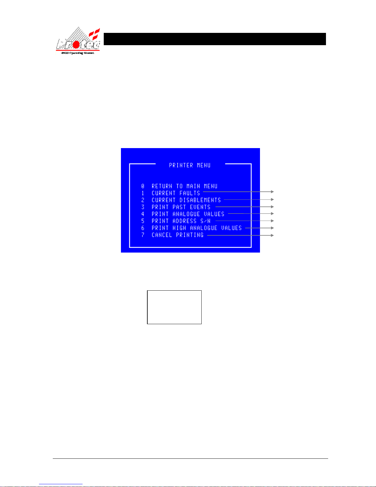
7.1 PRINTER MENU
• Function : This option allows current events, past events and ‘Sensor’ contamination levels on the
network to be printed.
• Selecting option : To select this option, press the number ‘3’ key from the ‘Main menu’ options.
Once selected, the LCD will display the following sub-menu options :-
• Print Address S/N: This option only applies to 6000 series loops.
• Selecting 2 options : Selecting an option while the DCN is already printing will display the following message
Press any key to return to the ‘Printer’ menu. Once the printer has completed its current
task a new option can then be selected.
• Exiting Option : To EXIT the ‘Printer’ menu and return to the ‘Main menu’ , press the ‘0’ or ‘ESC’ .
For further details
Refer to section 7.2
Refer to section 7.3
Refer to section 7.4
Refer to section 7.5
Refer to section 7.6
Refer to section 7.7
PLEASE WAIT
STILL PRINTING
Press a key
Page 26
93-310-10 Issue 4 Rev 5 Page 26 of 88 Copyright Protec Fire Detection PLC
6400 OPERATING MANUAL
7.2 PRINT CURRENT FAULTS
• Function : This option allows the user to print any ‘Faults’ that are currently on the system.
• Selecting Option : To select this option , press the number ‘1’ key from the ‘Printer menu’.
Once selected, the printer will print the ‘Current Faults’ in the following format :-
***************************
List of Current Faults
20 Aug 2006, 10:15:54
***************************
Time 20 Aug 2006 , 09:49:31
LOOP FAULT
Node X Loop X
**************************
• Exiting Option : Pressing the ‘0’ or ‘ESC’ key , will EXIT ‘Print current faults’ and return to the ‘Main menu’
options. This will NOT stop the printer from printing the ‘List of current faults’. To stop the
printer, select option number ‘7’ from the ‘Printer menu’.
Time & date the fault
occurred.
The date & time when the
list of current faults was
printed.
Displays the Node /
Loop & location of the
fault
Note - If text has been
assigned to the node, then
the text will be displayed
rather than the node & loop
No
Fault description
Page 27
93-310-10 Issue 4 Rev 5 Page 27 of 88 Copyright Protec Fire Detection PLC
6400 OPERATING MANUAL
7.3 PRINT CURRENT DISABLEMENTS
• Function : This option allows the user to print any ‘Disablements’ that are currently on the
system.
• Selecting Option : To select this option press the ‘2’ key from the ‘Printer menu’.
Once selected, the printer will print any ‘Current Disablements’ in the following
format :-
***************************
List of Current Disablements
20 Aug 2006, 10:15:54
***************************
Location Text
Node X Loop X Address X Zone X
****************************
If there are currently NO disablements on the system, the LCD will indicate the following indication :-
NO Disablements to Print
Press a Key
Press any key to return to the ‘Print events’ menu.
• Exiting Option : Pressing the ‘0’ or ‘ESC’ key , will EXIT ‘Print current disablements’ and return to the
‘Main menu’ options. This will NOT stop the printer from printing the ‘List of current
disablements’. To stop the printer, select option number ‘7’ from the ‘Printer menu’.
The date & time when the
list of current disablements
was printed.
Page 28
93-310-10 Issue 4 Rev 5 Page 28 of 88 Copyright Protec Fire Detection PLC
6400 OPERATING MANUAL
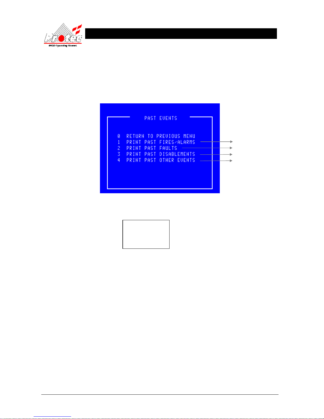
7.4 PRINT PAST EVENTS
• Function : This option allows the user to print events from the 1000 event ‘Historic log’.
• Selecting option : To select this option press the ‘3’ key from the ‘Printer’ menu. On selecting this option
the LCD will display the following sub-menu :-
• Selecting 2 options : Selecting an option while the DCN is already printing an event will
display the following message :-
Press any key to return to the ‘Printer’ menu. Once the printer has completed
printing, a new option can then be selected.
• Exiting Option : Pressing the ‘0’ or ‘ESC’ key , will EXIT ‘Past events’ menu and return to the
‘Printer menu’ options.
For further details
Refer to section 7.4.1
Refer to section 7.4.2
Refer to section 7.4.3
Refer to section 7.4.4
PLEASE WAIT
STILL PRINTING
Press a key
Page 29
93-310-10 Issue 4 Rev 5 Page 29 of 88 Copyright Protec Fire Detection PLC
6400 OPERATING MANUAL
7.4.1 PRINT PAST FIRES / ALARMS
• Function : This option allows the user to print fire events from the 1000 event ‘Historic log’.
• Selecting option : To select this option press the ‘1’ key from the ‘ Past events’ menu. On selecting this
option, the Printer will print the ‘Past fire events’ in the following format :-
***************************
List of past fire / alarm events
20 Aug 2006, 10:15:54
***************************
Location Text
Alarm text
Time 20 Aug 2006, 10:13:35
FIRE in ZONE X
Node X Loop X Address X Type
***************************
• Exiting Option : Selecting option ‘7 Cancel printing’ from the ‘Printer menu’ , will abort the print-out of
the ‘Past fire / alarms’.
7.4.2 PRINT PAST FAULTS
• Function : This option allows the user to print past fault events from the 1000 event ‘Historic log’.
• Selecting option : To select this option press the ‘2’ key from the ‘Past events’ menu. On selecting this
option the Printer will print the ‘Past fault events’ in the following format :-
***************************
List of Past Fault events
20 Aug 2006, 10:15:54
***************************
Time 19 Aug 2006, 23:59:59
LOOP FAULT
Node X Loop X
****************************
• Exiting Option : Selecting option ‘7’ Cancel printing’ from the ‘Printer menu’ , will abort the print-out of
the ‘Past fault events’.
Time & date the fault
occurred.
The date & time when the
list of past faults was
printed.
Displays the Node /
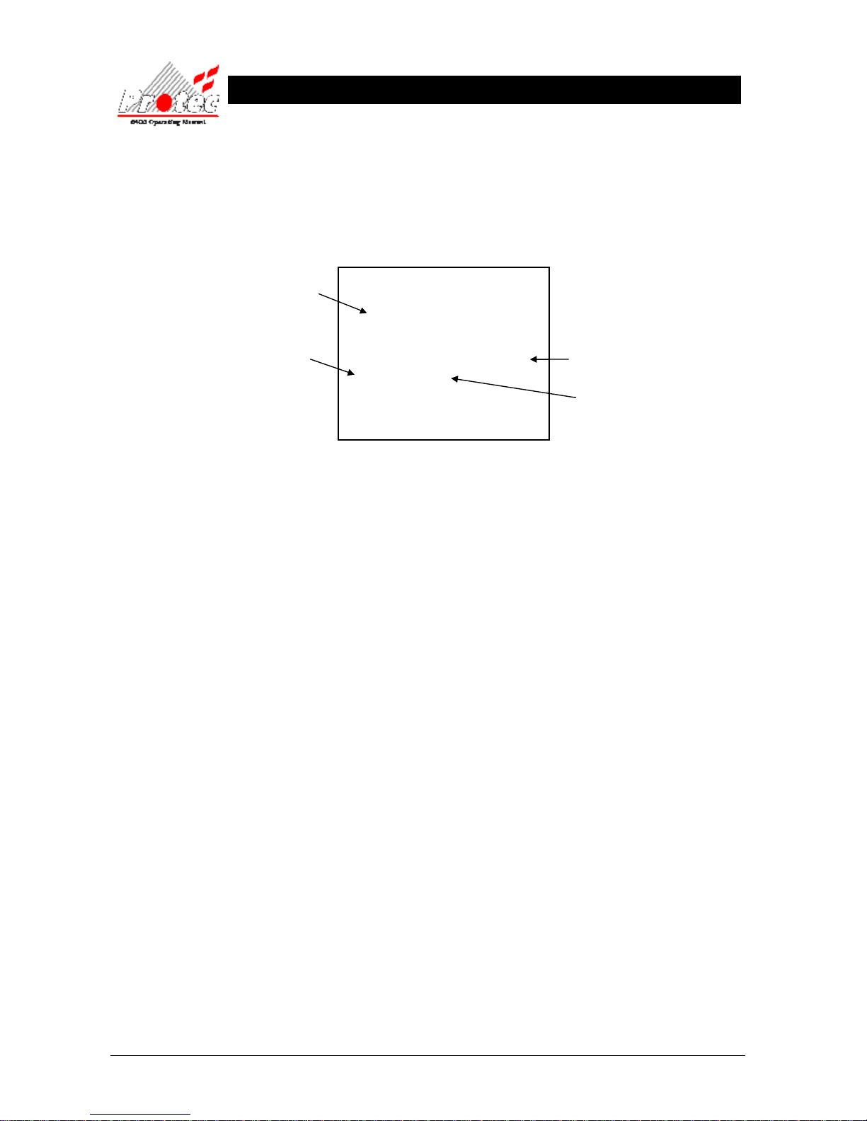
Loop & location of the
fault
Note - If text has been
assigned to the node, then
the text will be displayed
rather than the node & loop
No
Fault description
Location of device
The Date & time the
‘List of past fires’ was printed
The fire ZONE where the device
was activated
Up to 60 characters of location text &
up to 60 characters of alarm text
(optional)
The time & date the fire
event occurred
Page 30
93-310-10 Issue 4 Rev 5 Page 30 of 88 Copyright Protec Fire Detection PLC
6400 OPERATING MANUAL
7.4.3 PRINT PAST DISABLEMENTS
• Function : This option allows the user to print past disablement events from the
1000 event ‘Historic log’.
• Selecting option : To select this option press the ‘3’ key from the ‘Past events’ menu. On selecting this
option the Printer will print the ‘Past disablement events’ in the following format :-
***************************
List of Past Disablements
20 Aug 2006, 10:15:54
***************************
Location text
Time 19 Aug 2006, 23:59:59 Zone 1
Device disabled, Reception
Node X Loop X Address X
****************************
• Exiting Option : Selecting option ‘7’ Cancel printing’ from the ‘Printer menu’, will abort the print-out of
the ‘Past disablement events’.
7.4.4 PRINT PAST OTHER EVENTS
• Function : This option allows the user to print other past events from the 1000 event ‘Historic log’.
The events printed in this option, are all the events which do NOT come under Fire, Fault
or disablement events. ie when a security code was entered etc….
• Selecting option : To select this option press the ‘4’ key from the ‘Past events’ menu.
On selecting this option the Printer will print the ‘Other events’ in the following format :-
***************************
List of Past other events
20 Aug 2006, 10:15:54
***************************
Time 20 Aug 2006, 09:49:31
NEW SECURITY CODE from Node 1
****************************
• Exiting Option : Selecting option ‘7’ Cancel printing’ from the ‘Printer menu’ , will abort the print-out of
the ‘Past other events’.
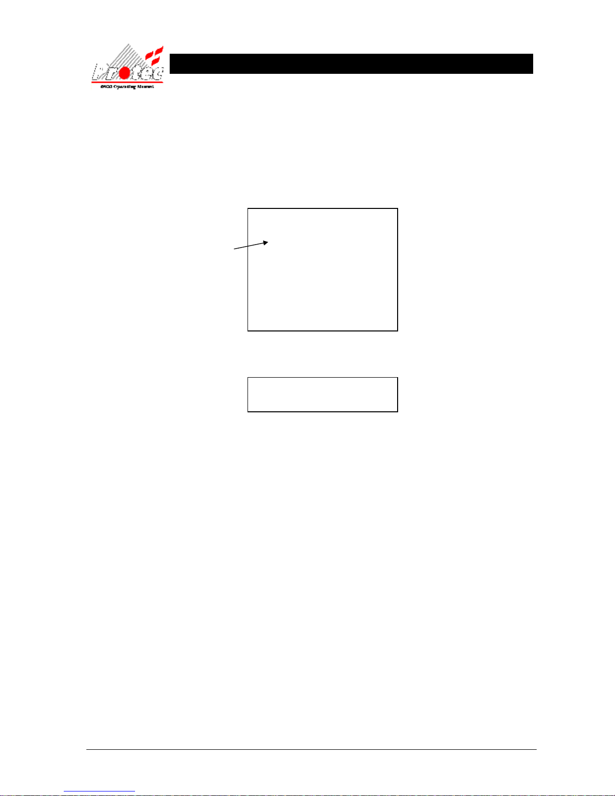
Time & date the device
was disabled.
The date & time when the
list of past disablements
was printed.
Time & date the event
occurred.
The date & time when the
list of other events was
printed.
Node from which the
device was disabled
Page 31
93-310-10 Issue 4 Rev 5 Page 31 of 88 Copyright Protec Fire Detection PLC
6400 OPERATING MANUAL
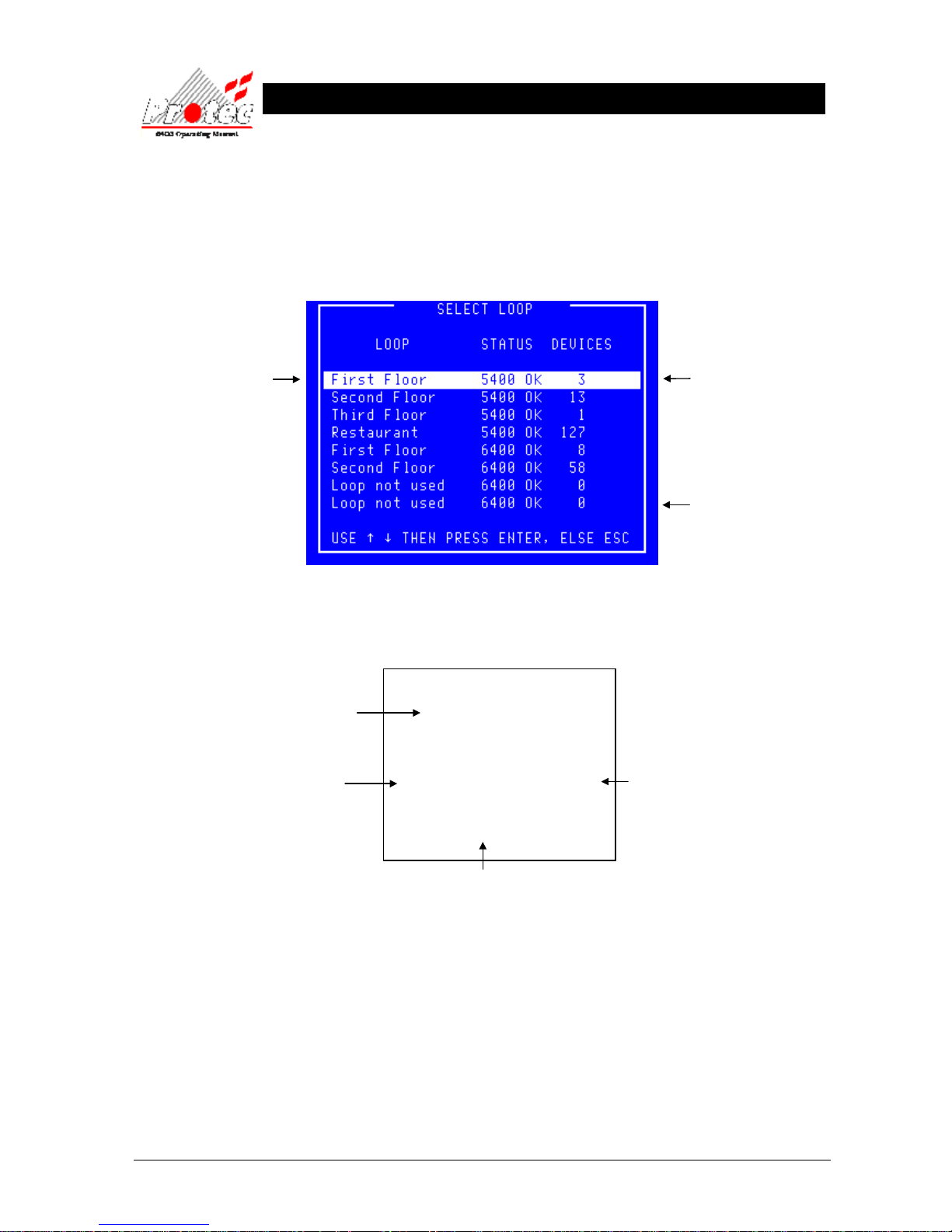
7.5 PRINT ANALOGUE VALUES
• Function : This option allows the user to print the return ‘Analogue data’ for any loop device on the
network.
• Selecting option : To select this option press the ‘4’ key from the ‘Printer menu’ menu.
Once selected, the LCD will display the following ‘Select Loop’ menu :-
• Select Loop : Use the High-light bar to select the ‘Node & Loop’ number of the devices to print their
analogue data. Once selected, the display will return to the ‘Printer menu’ and the printer
will print-out a list of the analogue data, for the loop selected in the following format :-
• Threshold levels For details on the analogue threshold levels, refer to section ‘13.1 Analogue values.’
• Exiting Option To abort the ‘Print analogue values’ print-out, select option number
‘7’ Cancel printing’ from the ‘Printer menu’.
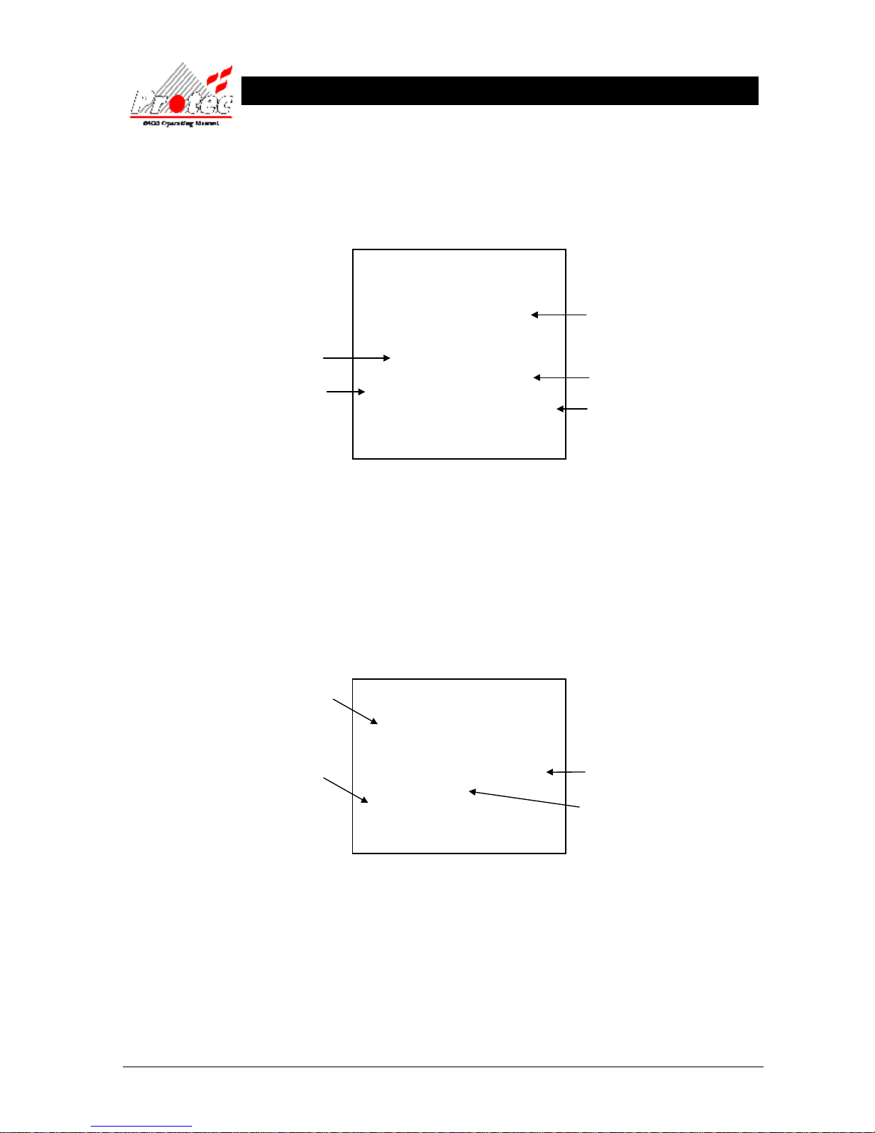
Displays the Node and
Loop Number
or a text description if
the option has been
specified.
Displays the number of
devices on each loop.
Indicates the Loop status.
6400 OK = Loop healthy.
No card
= No loop available.
***************************
List of Analogue values
20 AUG 2006, 12:59:12
***************************
Node X Loop X
address 1 MCP Value = xx
address 2 OPT Value = xx
address 3 ION Value = xx
address 4 HEAT Value = xx
Indicates type of device
MCP
= Manual call point or Interface unit
Ion = Ionisation smoke sensor
Opt = Optical smoke sensor
Heat = Temp sensor
Indicates the address number
on the specified loop
Displays the Current Analogue reading
for each device on the loop
The date & time when the
list of Analogue values was
printed.
Page 32
93-310-10 Issue 4 Rev 5 Page 32 of 88 Copyright Protec Fire Detection PLC
6400 OPERATING MANUAL
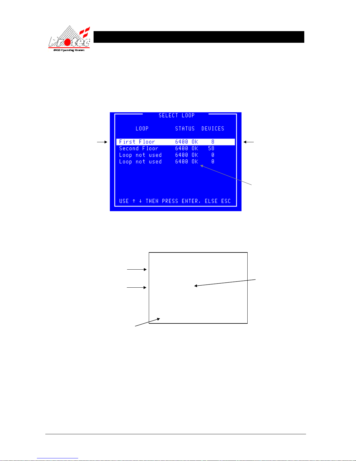
7.6 PRINT ADDRESS S/N
• Function : This option allows the user to print the address and serial numbers for all devices on any
‘6000’ series loop on the network.
• Selecting option : To select this option press the ‘5’ key from the ‘Printer menu’ menu.
Once selected , the LCD will display the following ‘Select Loop’ menu :-
• Select Loop : Use the High-light bar to select the ‘Node & Loop’ number from which to print the address
and serial number data. Once selected, the display will return to the ‘Printer menu’ and the
printer will print-out a list of the device serial numbers and address data, for the loop
selected in the following format :-
• Exiting Option To abort the ‘Print address S/N’ print-out, select option number ‘7’ Cancel printing’ from
the ‘Printer menu’.
Displays the Node and
Loop Number
or a text description if the
option has been specified.
Displays the number of
devices on each loop.
Indicates the Loop status.
6400 ok = Loop healthy.
No card
= No loop available.
***************************
List of device serial numbers
20 AUG 2006, 13:43:02
***************************
Node X Loop X
Add Ser Type Iso Ver Sns DNSns
029 5265C1 HEAT 001 005 OFC OFC
028 5265C7 HEAT 001 005 OFC OFC
021 3D0904 ION 002 004 OFC OFC
002 1E849A OP_HT 009 006 OFC HPO
Device serial number
Indicates the address
number on the specified
loop
Displays the Current type reading for
each device on the loop
The date & time that the list
of serial numbers and
addresses was printed.
Page 33
93-310-10 Issue 4 Rev 5 Page 33 of 88 Copyright Protec Fire Detection PLC
6400 OPERATING MANUAL
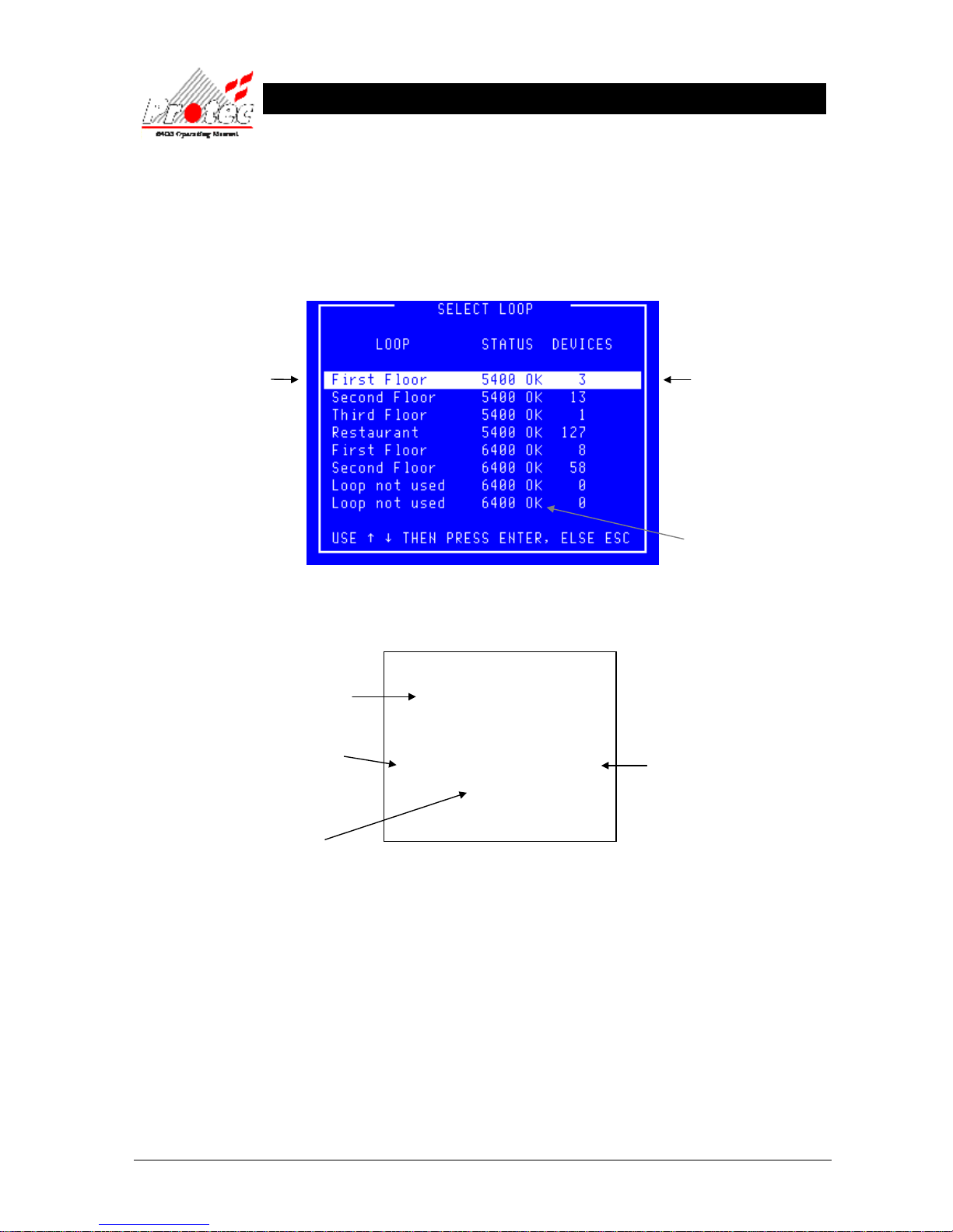
7.7 PRINT HIGH ANALOGUE VALUES
• Function : This option allows the user to print the ‘Analogue values’ for any loop device on the
network that has a higher value than is considered ‘Normal’.
• Selecting option : To select this option press the ‘6’ key from the ‘Printer menu’ menu.
Once selected, the LCD will display the following ‘Select Loop’ menu :-
• Select Loop : Use the High-light bar to select the ‘Node & Loop’ number of the devices to print their
analogue data. Once selected, the display will return to the ‘Printer menu’ and the printer
will print-out a list of the high analogue data, for the loop selected in the following format :-
• Blank printout It is probable that no devices will be listed for the selected loop since all are considered
normal.
• Threshold levels For details on the analogue threshold levels, refer to section ‘13.1 Analogue values.’
• Exiting Option To abort the ‘Print high analogue values’ print-out, select option number
‘7’ Cancel printing’ from the ‘Printer menu’.
7.8 CANCEL PRINTING
• Function : This option allows the user to stop the printer from printing at any time.
• Selecting option : Selecting option ‘7’ from the ‘Printer menu’ will abort any current print-out.
***************************
List of high Analogue values
20 AUG 2006, 12:04:59
***************************
Node X Loop X
address 3 ION Value = xx
address 4 HEAT Value = xx
Indicates type of device
MCP
= Manual call point or Interface unit
Ion = Ionisation smoke sensor
Opt = Optical smoke sensor
Heat = Temp sensor
Indicates the address number
on the specified loop
Displays the Current Analogue reading
The date & time when the
list of high Analogue values
was printed.
Displays the Node and
Loop Number
or a text description if
the option has been
specified.
Displays the number of
devices on each loop.
Indicates the Loop status.
6400 OK = Loop healthy.
No card
= No loop available.
Page 34
93-310-10 Issue 4 Rev 5 Page 34 of 88 Copyright Protec Fire Detection PLC
6400 OPERATING MANUAL
D
DII
S
S
A
A
B
BLL
E
E
M
M
E
E
N
N
T
T
M
M
E
E
N
N
U
U
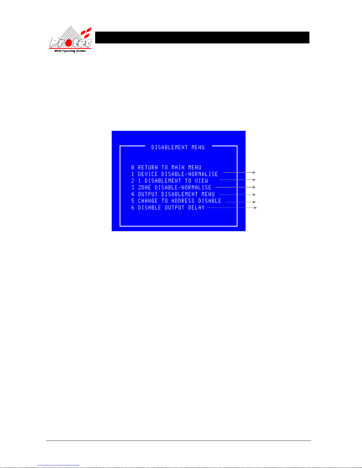
8.1 DISABLEMENT MENU
• Function : This option allows the operator to disable devices, zones and outputs.
• Selecting option : To select the ‘Disablement menu’ , select the number ‘4’ key from the ‘Main menu’
options. Once selected the LCD will display the following disablement options :-
• Exiting Option : To EXIT the ‘Disablement menu’ and return to the ‘Main Menu’, press the ‘0’ Key.
• Option 6 : Option 6 is only available if the Output Delay Disablement feature has been enabled.
For further details
Refer to section 8.2
Refer to section 8.3
Refer to section 8.4
Refer to section 8.5
Refer to section 8.6
Refer to section 8.7
Page 35
93-310-10 Issue 4 Rev 5 Page 35 of 88 Copyright Protec Fire Detection PLC
6400 OPERATING MANUAL
8.2 DEVICE DISABLE / NORMALISE
• Function : This option allows the disablement / normalisation of any Loop device on the system.
When a device is disabled then it is the input that is actually disabled hence it will be prevented
from producing a Fire or Fault condition at the control panel.
If the device being disabled is an output device then the device will no longer be able to report a
fault however the output is not disabled and will activate if told to do so by the panel.
If the device was in fault when it was disabled then the fault is not removed by disabling the device.
• Selecting option : To select this option press the ‘1’ key while in the ‘Disablement menu’.
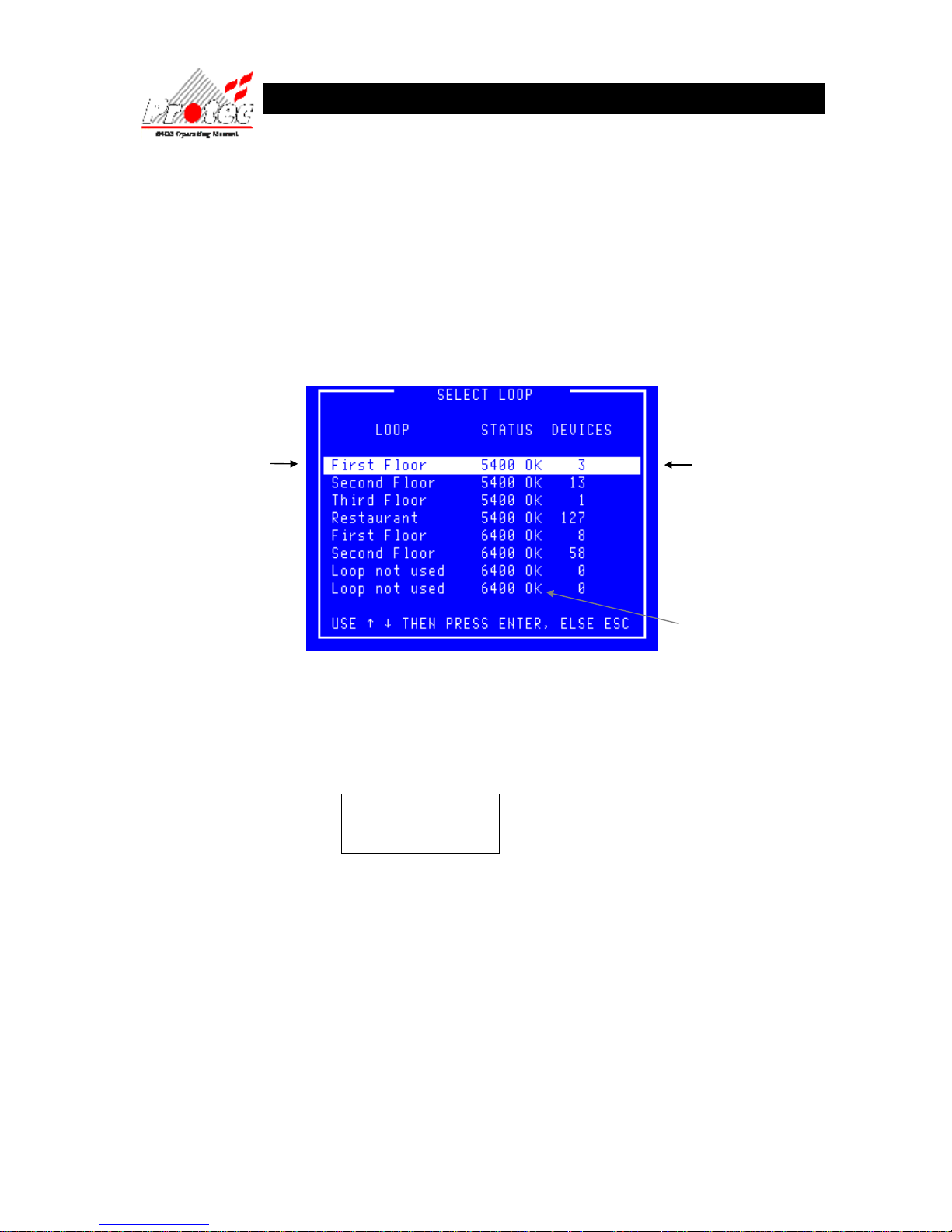
Once selected the panel will display the ‘Select Loop’ menu :-
• Selecting Loop : Use the High-light bar to select the Node & Loop number of the device to be Disabled
/ Normalised and then press the ENTER key.
Once selected the panel will request data from the ‘Node’ selected. While the data is being
requested, the LCD displays the following message :-
Data Requested
Please Wait
Displays the Node and
Loop Number or a text
description if the option
has been specified.
Displays the number of
devices on each loop.
Indicates the Loop status.
6400 OK = Loop healthy.
No card
= No loop available.
Page 36
93-310-10 Issue 4 Rev 5 Page 36 of 88 Copyright Protec Fire Detection PLC
6400 OPERATING MANUAL
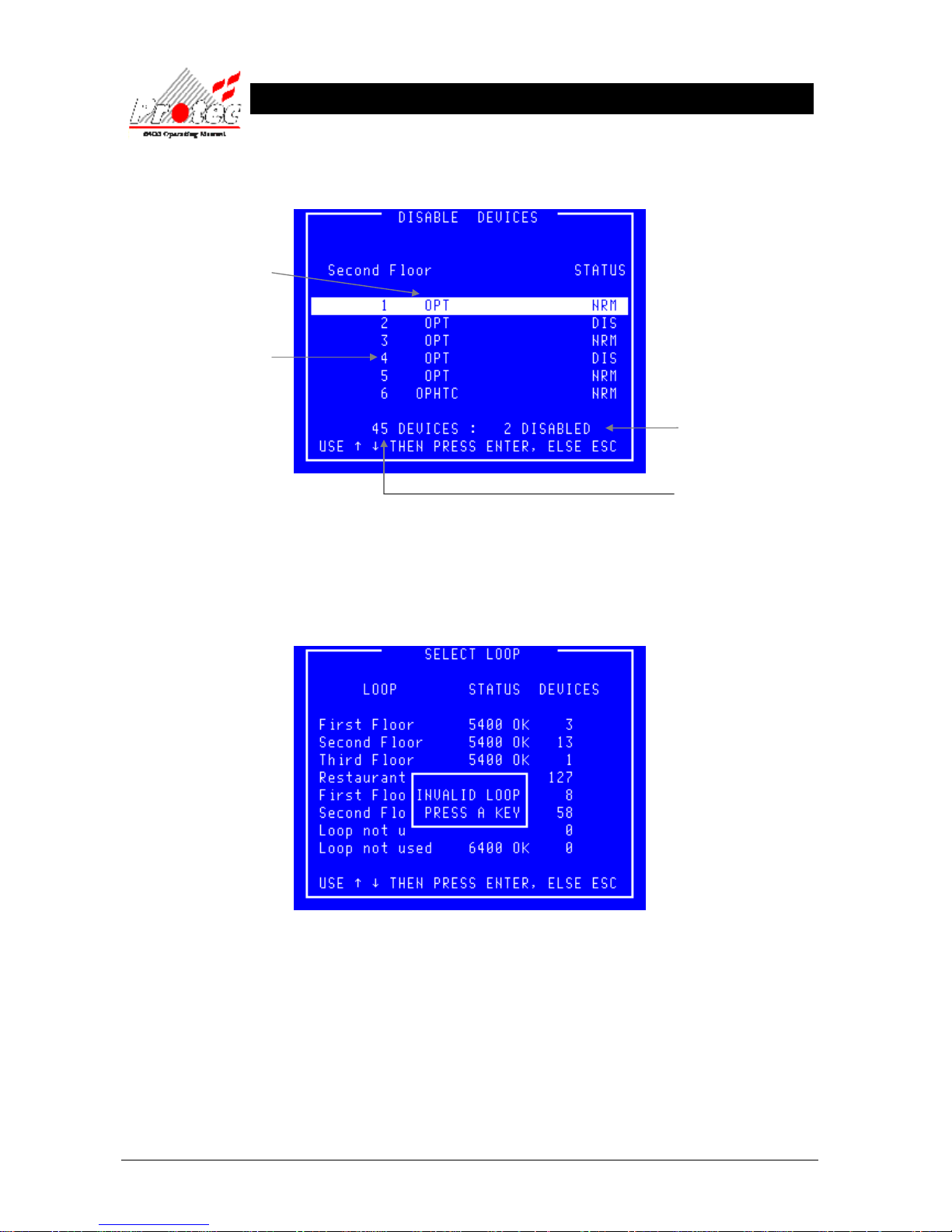
Once all the data has been received from the ‘Node’, the following ‘Disable devices’
Screen will be displayed :-
• Selecting an invalid If an invalid loop is selected ie) No devices present on the loop, the LCD will
loop. display the following message :-
Press any key to return to the ‘Disable device’ screen , where a valid loop should be selected.
Device type
Status
NRM - Device is not disabled
DIS - Device has been
disabled individually
DSZ – Device is disabled
because it is part of a disabled
zone
DSG - Device is disabled
because it is part of a disabled
group
It is possible for a device to be
disabled for multiple reasons.
The number of devices
disabled on this Loop.
Total number of devices
Logged onto the Loop
Either Location Text or
address numbers for each
device on the selected
loop. To display either
address Number or text
location data, this is
selected in the
‘Disablement menu’
Option Number ‘5 ‘
Change address /
location text’ (refer to
section 8.6)
Page 37
93-310-10 Issue 4 Rev 5 Page 37 of 88 Copyright Protec Fire Detection PLC
6400 OPERATING MANUAL
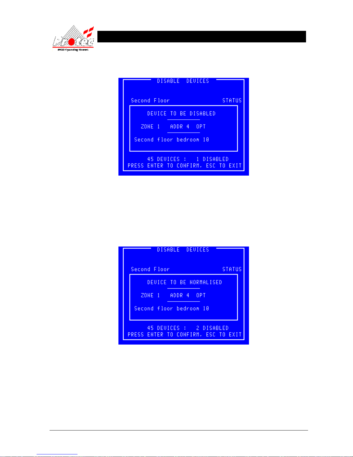
• Disable a Device : To disable a device use the High-light bar to select the device for disablement, then press the
‘ENTER’ key. The display will show :-
• Exiting Option : Press ‘ESC’ to abandon to disablement.
• Disablement : Upon pressing the ‘ENTER’ key, the number of disabled devices will increment (shown at
the bottom right of the display). The panel will illuminate the ‘Disablement’
LED on the control panel and sound the buzzer intermittently.
To mute the buzzer, press the ‘Accept’ button.
• Normalise a Device : To normalise a device use the High-light bar to select the Device for Normalisation, and then
press the ENTER key. The display will show :-
• Exiting Option : Press ‘ESC’ to abandon to normalisation.
• Normalisation : Upon pressing the ENTER key the number of disabled devices will decrement (shown at
the bottom right of the display). The panel’s ‘Disablement’ LED will also extinguish.
Page 38
93-310-10 Issue 4 Rev 5 Page 38 of 88 Copyright Protec Fire Detection PLC
6400 OPERATING MANUAL
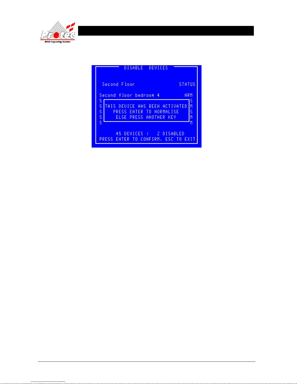
If a disabled device activated while in an disabled condition, when the device is selected
for normalisation the LCD will display the following warning message
• Exiting Option : Press ‘ESC’ then physically inspect the device and check for the cause of the
activation. Ie) Broken glass in the Break glass point, dust contamination within a smoke
sensor etc. This will return the display to the ‘Disablement menu’ and the device will
remain disabled.
• Selecting Option : Once the cause has been rectified, return to this menu and press the ‘ENTER’ key to
normalise the device. Since the system is aware that this device has been activated it will
perform a loop reset.
Page 39
93-310-10 Issue 4 Rev 5 Page 39 of 88 Copyright Protec Fire Detection PLC
6400 OPERATING MANUAL
8.3 DISABLEMENTS TO VIEW
• Function : This option allows the operator to view any devices on the network that have been
disabled, and will also allow each of those devices to be normalised .
• Selecting option : To select this option press the number ‘2’ key while in the ‘Disablement Menu’ .
The ‘Disablements to view’ option will indicates how many devices can be viewed
ie If 5 devices are currently disabled the ‘Disablements to view’ option will be displayed as
the following :-
2 5 Disablements to View
If NO disablements are on the system, the ‘Disablements to view’ option will display the
following :-
2 NO Disablements to View
Selecting the ‘Disablements to view’ option will have NO effect if NO devices are
currently disabled on the network.
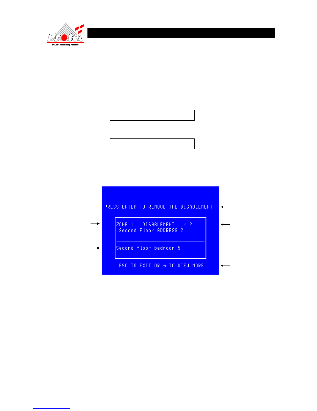
• Viewing disablements : Selecting the ‘Disablements to view’ option will display any devices which are currently
disabled in the following format :-
The location text will only be
displayed if text has been
specified for each device.
Details of the disabled
device.
The option to press enter is not
offered for all disablements.
Pressing the → key will
scroll through each
disablement
Number of
disablements on the
network.
Page 40
93-310-10 Issue 4 Rev 5 Page 40 of 88 Copyright Protec Fire Detection PLC
6400 OPERATING MANUAL
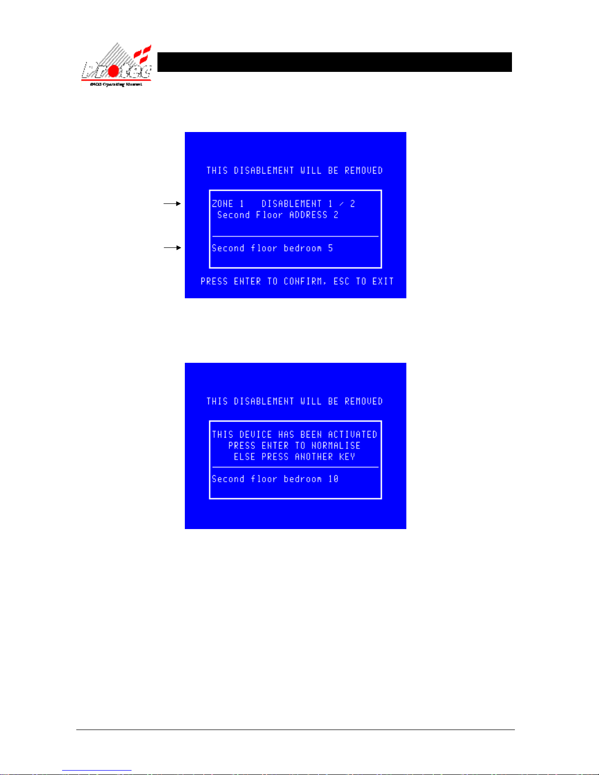
• Remove Disablement: While viewing the disablements , press the ENTER key on the device you require
normalising when it is being displayed. The display will then show the following :-
Pressing the ENTER key will Normalise the device currently being displayed.
If a disabled device activated while being disabled, when the device is selected for
normalisation the LCD will display the following warning message :-
• Exiting Option : Press ‘ESC’ then physically inspect the device and check for the cause of the
activation. Ie) Broken glass in the Break glass point, dust contamination within a smoke
sensor etc. This will return the display to the ‘Disablement menu’ and the device will
remain disabled.
• Selecting Option : Once the cause has been rectified, return to this menu and press the ‘ENTER’ key to
normalise the device. Since the system is aware that this device has been activated it will
perform a loop reset.
The location text will only be
displayed if text has been
specified for each device.
Details of the disabled
device.
Page 41
93-310-10 Issue 4 Rev 5 Page 41 of 88 Copyright Protec Fire Detection PLC
6400 OPERATING MANUAL
8.4 ZONE DISABLE / NORMALISE
• Function : This option allows any zone on the system to be disabled and subsequently normalised.
• Selecting option : To select this option press the number ‘3’ key while in the ‘Disablement Menu’ .
The ‘Zone disable / normalise’ option will be displayed as shown below :-
• Exiting Option : To EXIT the ‘Zone disable / normalise’ menu and return to the ‘Disablement Menu’,
press the ‘Esc’ Key.
• Manual class : When the system was installed, the engineer can define certain loop devices as
‘Manual Class’. These devices are typically manual call points and when defined as
‘Manual Class’ will ignore a zone disablement and remain active. For example this option
permits sensors that could false alarm due to dust during building work to be disabled
whilst maintaining the operation of manual call points should an employee see a fire.
Page 42
93-310-10 Issue 4 Rev 5 Page 42 of 88 Copyright Protec Fire Detection PLC
6400 OPERATING MANUAL
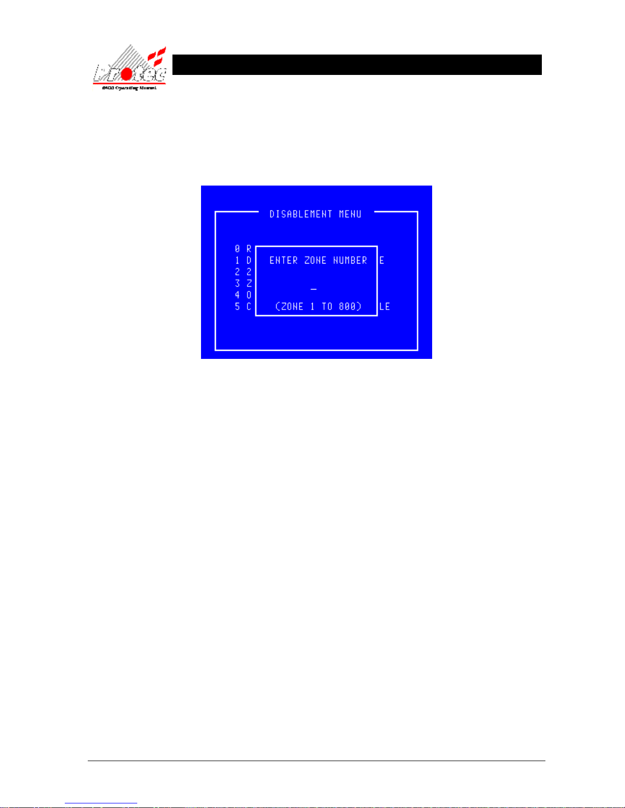
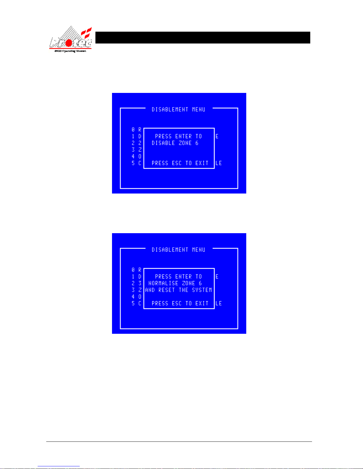
• Select a Zone : The menu will accept a zone number between 1 and 800 inclusive. Zones greater than 100
are only used on an expanded system. Once a zone has been selected the system checks
whether this zone is already disabled and either offers the opportunity to disable (or
normalise) the selected zone as shown below :-
• Zone disable : To confirm the disablement press the ‘Enter’ key.
• Exiting Option : To cancel the zone disablement press the ‘Esc’ key.
• Zone normalise : Prior to the normalisation the user should visually inspect for broken glass in any
disabled breakglass. The menu asks for confirmation of the normalisation. To confirm the
zone normalisation, press the ‘Enter’ key.
Note that the loop devices will be reset upon the normalisation. However if a device had
activated during the disablement period eg broken glass on a manual call point then if that
glass has not been replaced prior to the normalisation that device will generate an alarm as
soon as it is normalised.
• Exiting Option : To cancel the zone normalisation and leave the selected zone disabled, press the ‘Esc’ key.
Page 43
93-310-10 Issue 4 Rev 5 Page 43 of 88 Copyright Protec Fire Detection PLC
6400 OPERATING MANUAL
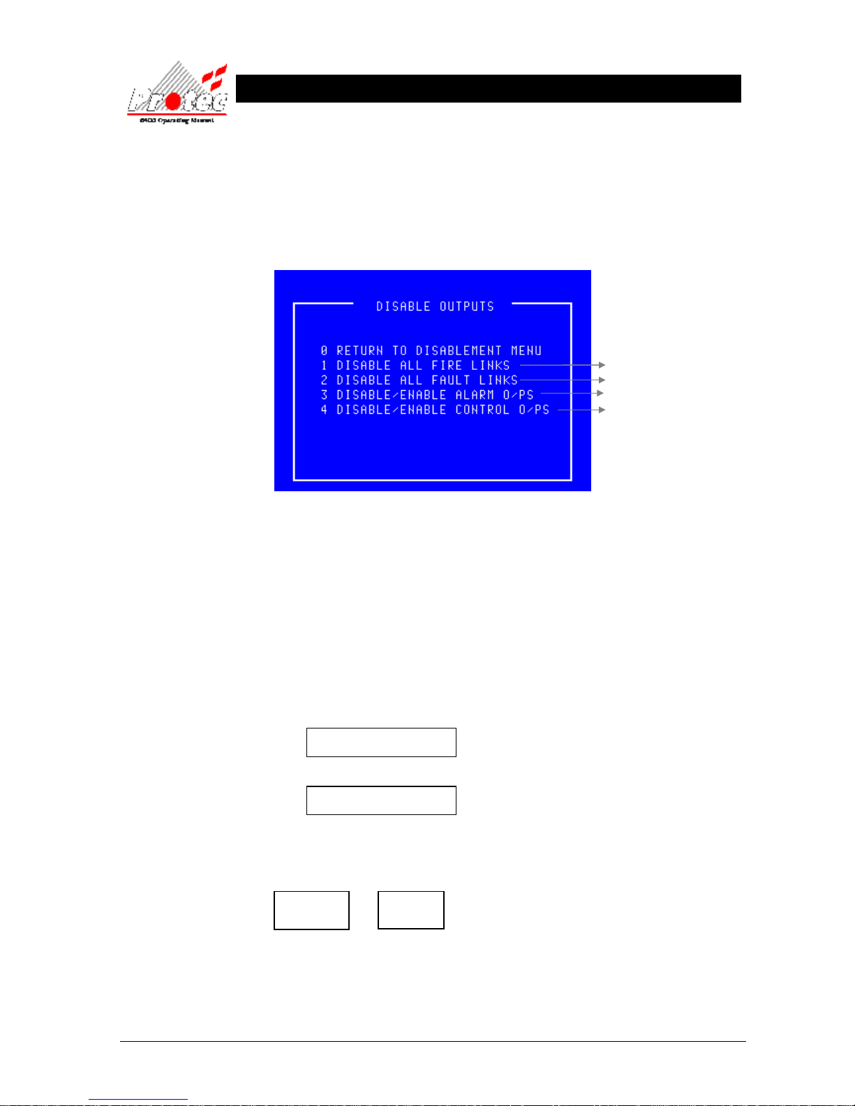
8.5 OUTPUT DISABLEMENT MENU
• Function : This option allows the operator to disable output devices or the ‘fire station link’.
• Selecting option : To select the ‘Output disablement menu’ option , select the number ‘4’ key from the
‘Disablement menu’. Once selected the LCD will display the following output disablement
options :-
• Exiting Option : To EXIT the ‘Disable outputs menu’ and return to the ‘Disablement Menu’, press the ‘0’
or ‘Esc’ key.
• General Alarm : A General Alarm panel is not intended to summon the fire brigade therefore option ‘1’ is
not relevant to a General Alarm system.
8.5.1 DISABLE / ENABLE FIRE LINK
• Function : This option allows the disablement and enablement of the Fire brigade link.
Note - This option is able to disable the signal that is sent to the fire brigade via a
manned centre only if the signal is connected to the dedicated ‘Fire link’ output terminals.
• Selecting Option : To select this option , press the number ‘1’ key from the ‘Disable outputs menu’ .
When this option is selected, the menu option will toggle between :-
1 Disable all Fire Links
and
1 Enable all Fire Links
• Disable all fire Links :To disable ‘All fire links’ press ‘1’ while the display is showing ‘Disable all fire
links’ , the panel buzzer will sound intermittently and the following disablement LEDs will
illuminate :-
• Buzzer mute : The panel buzzer can be muted by pressing ‘Accept’.
• Enable all fire Links : To enable ‘All fire links’ press ‘1’ while the display is showing ‘Enable all fire
links’ . This will extinguish the ‘Disablement’ & ‘Fire link disabled’ LEDs.
For further details
Refer to section 8.5.1
Refer to section 8.5.2
Refer to section 8.5.3
Refer to section 8.5.4
Disablement Fire Link
Disabled
Page 44

93-310-10 Issue 4 Rev 5 Page 44 of 88 Copyright Protec Fire Detection PLC
6400 OPERATING MANUAL
8.5.2 DISABLE / ENABLE FAULT LINK
• Function : This option allows the disablement and enablement of the Fault link.
Note - This option is able to disable the signal that is sent to the manned centre only if the
signal is connected to the dedicated ‘Fault link’ output terminals.
• Selecting Option : To select this option , press the number ‘2’ key from the ‘Disable outputs menu’ .
When this option is selected, the menu option will toggle between :-
2 Disable all Fault Links
and
2 Enable all Fault Links
• Disable all fire Links :To disable ‘All fault links’ press ‘2’ while the display is showing ‘Disable all fault
links’ , the panel buzzer will sound intermittently and the following disablement LED will
illuminate :-
• Buzzer mute : The panel buzzer can be muted by pressing ‘Accept’.
• Enable all fault Links :
To enable ‘All fault links’ press ‘2’ while the display is showing ‘Enable all fault
links’ . This will extinguish the ‘Disablement’ LED.
Disablement
Page 45
93-310-10 Issue 4 Rev 5 Page 45 of 88 Copyright Protec Fire Detection PLC
6400 OPERATING MANUAL
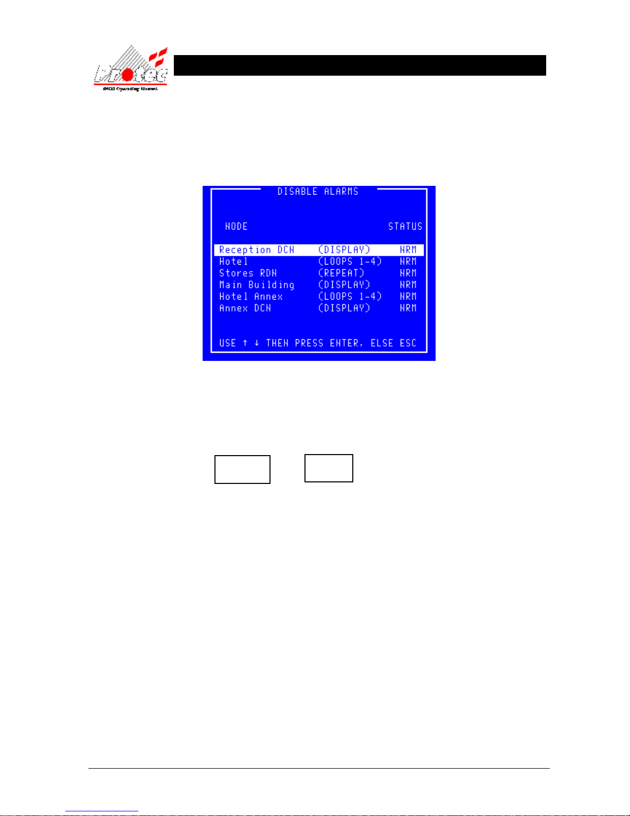
8.5.3 DISABLE / ENABLE ALARM OUTPUTS
• Function : This option allows the disablement & enablement of the alarm outputs at specific nodes
on the network.
• Selecting Option : To select this option press the ‘3’ key while in the ‘Output Disablement menu’ .
• Disable Alarm O/Ps : To disable the alarm outputs on a node, use the arrow keys to select a node then press the
‘Enter’ key while the status for the selected node is showing ‘NRM’.
The status for the selected node will change to ‘DIS’, the panel buzzer will sound
intermittently and the following disablement LEDs will illuminate :-
• Buzzer mute : The panel buzzer can be muted by pressing ‘Accept’.
• Enable Alarm O/Ps : To enable the ‘Alarm Outputs’ on a node, use the arrow keys to select a node then press
the ‘Enter’ key while the status for the selected node is showing ‘DIS’.
The status for the selected node will change to ‘NRM’. The ‘Outputs disabled’ LED will
be extinguished if there are no longer any alarm outputs disabled on the system and the
‘Disablement’ LED extinguished if there are no longer any disablements on the system.
• Exiting the option : To exit the ‘Disable / Enable Alarm outputs’ option and return to the ‘Output Disablement
menu’ press the ‘ESC’ key.
Outputs
Disabled
Disablement
Page 46
93-310-10 Issue 4 Rev 5 Page 46 of 88 Copyright Protec Fire Detection PLC
6400 OPERATING MANUAL
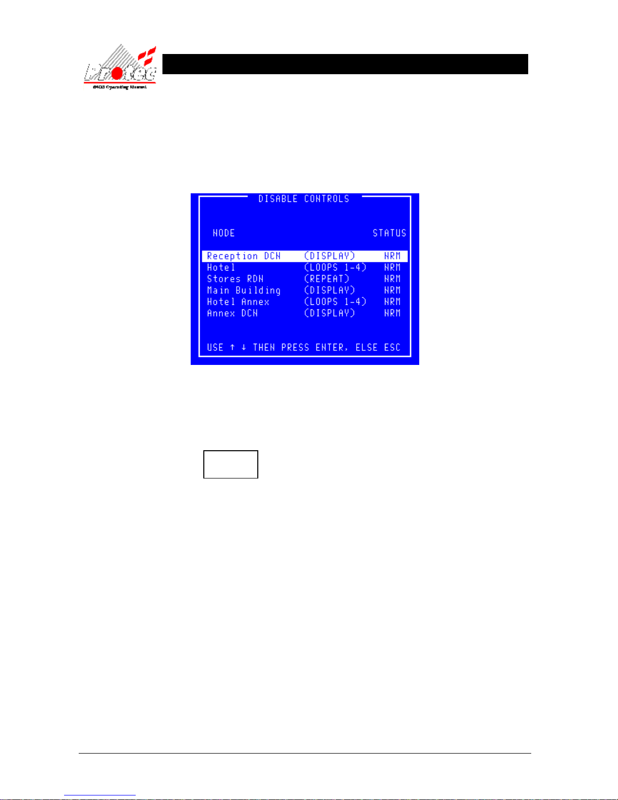
8.5.4 DISABLE / ENABLE CONTROL OUTPUTS
• Function : This option allows the disablement & enablement of the control outputs at a specific
node on the network.
• Selecting Option : To select this option press the ‘4’ key while in the ‘Output Disablement menu’ .
• Disable Control O/Ps :
To disable the ‘control outputs’ on a node, use the arrow keys to select a node then press
the ‘Enter’ key while the status for the selected node is showing ‘NRM’.
The status for the selected node will change to ‘DIS’ and the following LED will illuminate
:-
• Enable Control O/Ps :
To enable the ‘Control Outputs’ on a node, use the arrow keys to select a node then press
the ‘Enter’ key while the status for the selected node is showing ‘DIS’.
The status for the selected node will change to ‘NRM’. The ‘Disablement’ LED will be
extinguished if there are no longer any disablements on the system.
• Exiting the option : To exit the ‘Disable / Enable Control outputs’ option and return to the ‘Output
Disablement menu’ press the ‘ESC’ key.
Disablement
Page 47
93-310-10 Issue 4 Rev 5 Page 47 of 88 Copyright Protec Fire Detection PLC
6400 OPERATING MANUAL
8.6 CHANGE TO ADDRESS DISABLE
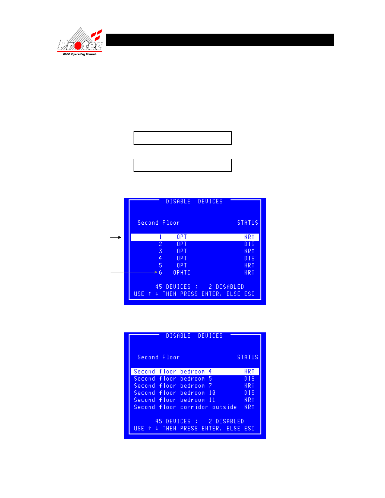
• Function : This option allows the user to alter the display of devices in the ‘Disablement menu’.
Devices can be displayed by their ‘character text’ location or by their ‘address
number’.
• Selecting Option : To select this option , press the number ‘5’ key while in the ‘Disablement menu’.
When the option has been selected, the sub-menu display will toggle between :-
5 Change to Address Disable
&
5 Change to Location Disable
• Device by address : The following is an example of the display if selected to ‘Address’ :-
• Device by Location : The following is an example of the display if selected to ‘Location’ :-
Address number
This option also displays
the type of each device
MCP = Manual Call point
OPT = Optical smoke
ION = Ionisation Smoke
HEAT = Heat Sensor
Page 48

93-310-10 Issue 4 Rev 5 Page 48 of 88 Copyright Protec Fire Detection PLC
6400 OPERATING MANUAL
8.7 OUTPUT DELAY DISABLEMENT
• Function : This option offers the user the ability to override the output delays programmed within the
system and activate the outputs immediately that there is a fire alarm. This option should be
used with care since removing the delays could interfere with the planned building
evacuation procedure.
The majority of 6400 systems have delays programmed. Typically these are used to give
time to investigate a fire before evacuating the building and signalling to the fire brigade.
To indicate that there are delays and therefore that the outputs are prevented from
activating immediately, the ‘Output Delay’ and the ‘Disablement’ LEDs will be lit.
• Disable Output Delay (ie enable the outputs immediately that an alarm occurs):
If there are delays programmed within the system then pressing option ‘6’ when offered the option
to ‘Disable Output Delay’ will override those delays.
Having removed the delay so that the outputs are free to activate immediately the ‘Output Delay’
LED will be extinguished. In addition if this was the only Disablement then the ‘Disablement’ LED
will also be extinguished.
• Warning : Once the delays have been overridden and the leds extinguished then there is no indication that the
panel is no longer operating in its intended mode.
Page 49
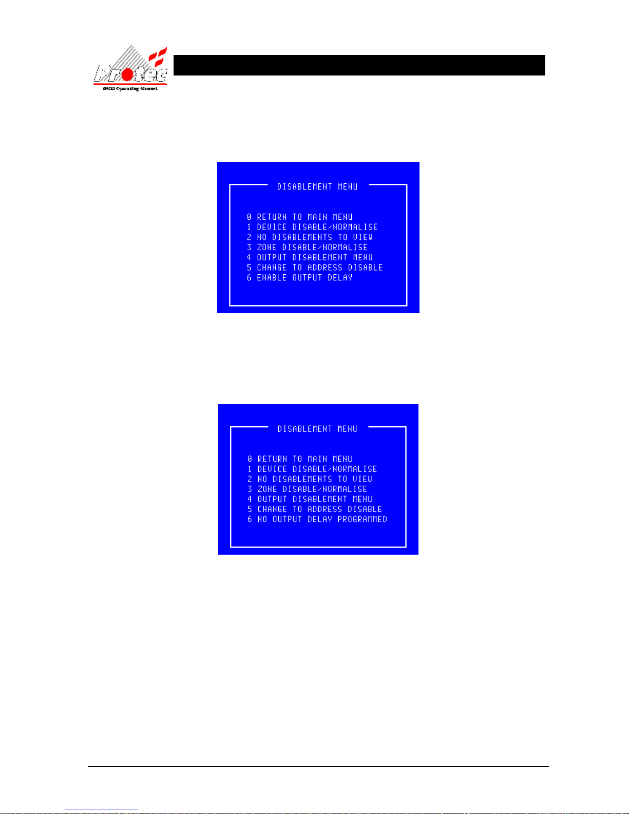
93-310-10 Issue 4 Rev 5 Page 49 of 88 Copyright Protec Fire Detection PLC
6400 OPERATING MANUAL
• Enable Output Delay (ie disable the outputs for the delay period):
If the programmed delays have been overridden then pressing option ‘6’ when offered the option
to ‘Enable Output Delay’ will reinstate the delays.
The ‘Output Delay’ and the ‘Disablement’ LEDs will now be lit. This is the state of the panel as it
was commissioned.
• No Delays Programmed : If there are no delays programmed within the system then pressing option ‘6’ will
not achieve anything.
Page 50
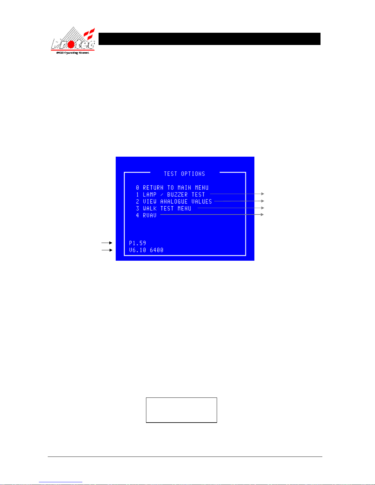
93-310-10 Issue 4 Rev 5 Page 50 of 88 Copyright Protec Fire Detection PLC
6400 OPERATING MANUAL
T
T
E
E
S
S
T
T
O
O
P
P
T
TII
O
O
N
N
S
S
9.1 TEST OPTIONS
• Function : This option allows the operator to check the operation of the DCN LED indication
(Lamps), inspect the return ‘Analogue reading’ from any device on the network
and operate a one man test option ‘Walk test’.
• Selecting option : To select the ‘Test Options’ Menu press number ‘5’ from the ‘Main Menu’ options.
Once selected the display will show the following Menu options on the LCD :-
• Software versions : At the bottom left of the ‘Test options’ menu screen, two numbers are displayed. These
two numbers represent the version number of software which the system is currently
operating under. An operating system with suffix ‘A’ implies a General Alarm System.
• RVAV : RVAV is only available for ‘6000’ series loops.
• Exiting option : To exit the ‘Test options’ menu and return to the ‘Main menu’ press the ‘0’ or ‘ESC’ key .
9.2 LAMP TEST
• Function : This option allows the operator to test that ALL LED indications on the DCN and that the
LCD display functions correctly.
Note - The ‘Lamp test’ will only be performed on the DCN where the option was selected,
ALL other DCN displays will remain untested.
• Selecting Function : To select this option press the ‘1’ key while in the ‘Test options’ menu. Once selected All
the LEDs will illuminate horizontally and then vertically one row at a time. The display
will show the following indication during the test :-
WARNING !
Display will be blanked
for a short interval
On completion of the ‘Lamp test’ the LCD will return to the ‘Test options’ menu.
For further details
Refer to section 9.2
Refer to section 9.3
Refer to section 9.4
Refer to section 9.5
Operating software version
Monitor Software version
Page 51
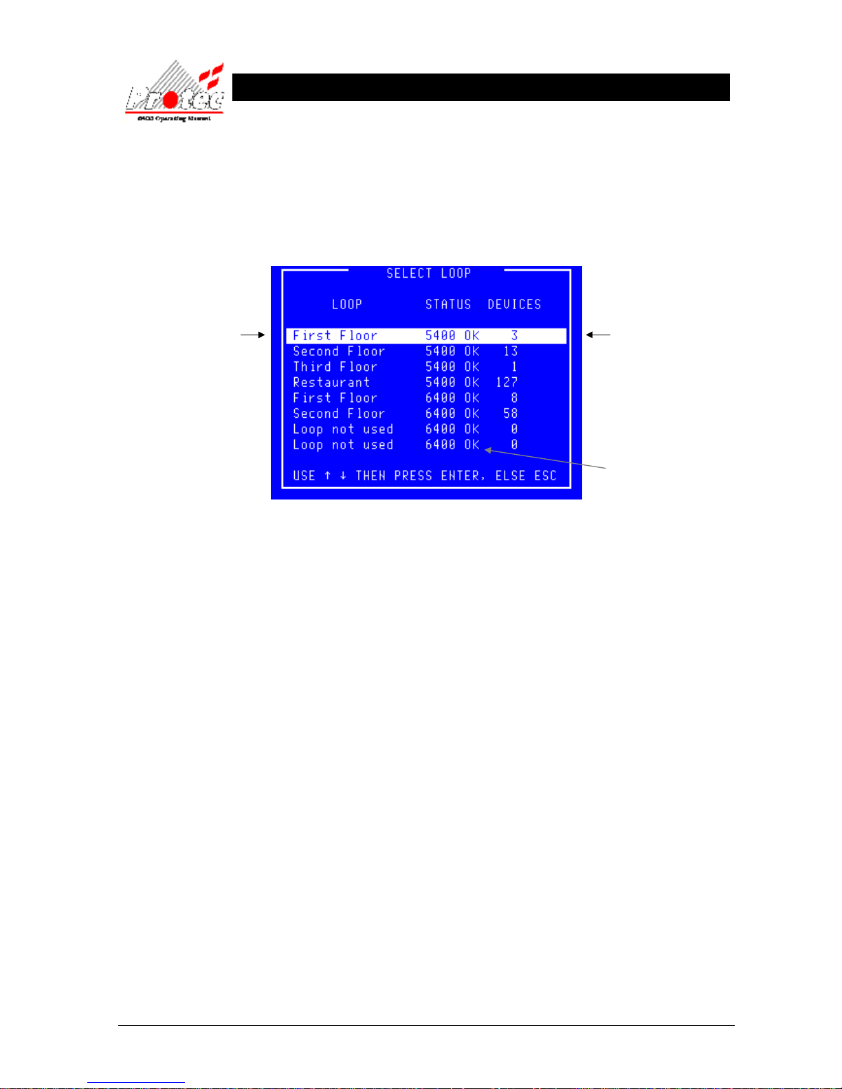
93-310-10 Issue 4 Rev 5 Page 51 of 88 Copyright Protec Fire Detection PLC
6400 OPERATING MANUAL
9.3 VIEW ANALOGUE VALUES
• Function : This allows the operator to select a specific loop to display the Analogue data for each
device currently on the Loop, on the LCD display in the form of a graph.
• Select Option : To select this option press the ‘2’ key while in the ‘Test options’ menu.
Once selected the LCD will display the ‘Select Loop’ sub-menu as shown below :-
• Selecting Loop : Use the High-light bar to select the Node & Loop number of the devices to display their
‘Analogue data’ on the LCD in the form of a graph. Once selected press the ‘ENTER’ key.
Displays the Node and
Loop Number or a text
description if the option
has been specified.
Displays the number of
devices on each loop.
Indicates the Loop status.
6400 ok = Loop healthy.
No card
= No loop available
Page 52
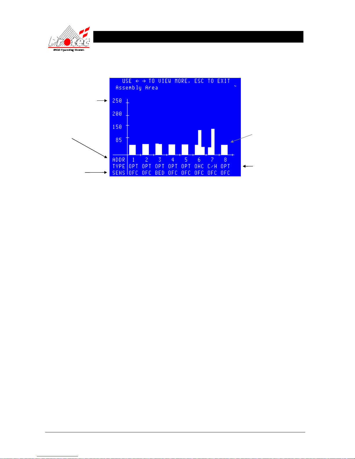
93-310-10 Issue 4 Rev 5 Page 52 of 88 Copyright Protec Fire Detection PLC
6400 OPERATING MANUAL
Analogue scale
Once all the data has been received from the ‘Node’, the following ‘Graph’ is displayed
showing the first 8 devices on the selected Loop, in the following format :-
Use the ← → keys to scroll through the next 8 devices on the selected Loop.
For details regarding the ‘Analogue data’ thresholds, refer to section 13
• Exiting Option : To EXIT the ‘View analogue values’ option and return to ‘Test options’ menu press the
‘ESC’ key.
• 5000/4000 Series : ‘5000’ and ‘4000’ series loops display a single column. The thresholds for ‘5000’ and
‘4000’ series devices are shown in section 13.3 and 13.4.
• HEA : This is a ‘6000’ series Heat device, column one is an average value (T
hist
), column two is a
current value (T1). Column three represents a rate of rise indication and only appears when
the heat channel is sensing a rising temperature. The fire decision algorithms look for this
rising temperature and column two being greater than column one by a set amount.
• O/H : This is a ‘6000’ series Optical Heat two channel device, column one is an average value
(T
hist
), column two is a current value (T1). Column three represents a rate of rise indication
and only appears when the heat channel is sensing a rising temperature. The fire decision
algorithms look for this rising temperature and/or column two being greater than column
one by a set amount.
• OHC : This is a ‘6000’ series Optical Heat CO three channel device, column one represents the
Optical value, column two the heat value and column three the CO value.
• C/H : This is a ‘6000 series’ CO Heat two channel device, column one represents the CO value,
column two the heat value. Column three is not used.
• 6000 Series : ‘6000’ Series devices not included in the above list show two columns, column one is an
average value (T
hist
), column two is a current value (T1). The fire decision algorithms look
for column two being greater than column one by a set amount.
The address number on the
selected loop
The device type
MCP = Manual call point
OPT = Optical smoke sensor
ION = Ionisation sensor
HEA = Heat sensor
O/H = Optical heat
Analogue data for
device no. 8
Device sensitivity
MED = Medium
OFC = Office mode
BED = Bedroom
HPO = High performance optical
Page 53
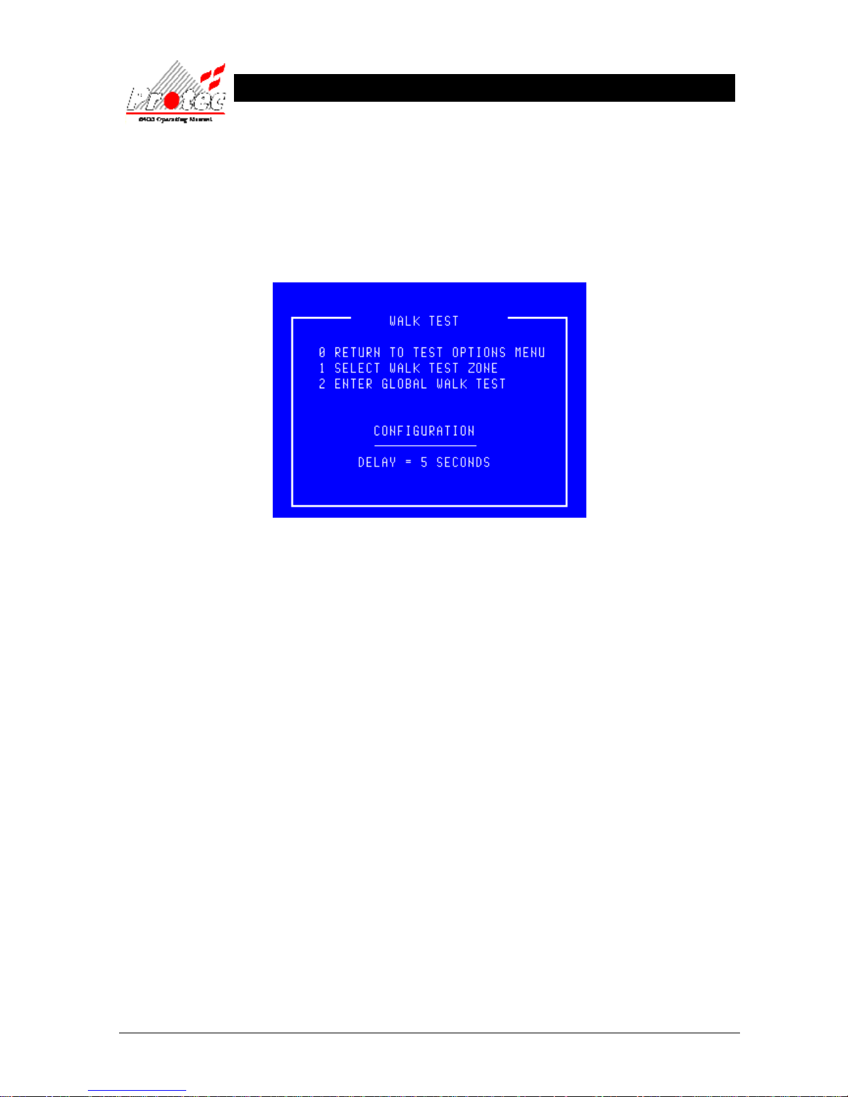
93-310-10 Issue 4 Rev 5 Page 53 of 88 Copyright Protec Fire Detection PLC
6400 OPERATING MANUAL
9.4 WALK TEST MENU
• Function : This option allows the operator to test ‘Loop devices’ without the need to return to the
control panel to silence and reset the fire event. When a device is tested the panel activates the
‘alarm outputs’ that are programmed for the device under test for a predetermined period (set by the
Protec engineer during commissioning), then the ‘alarm outputs’ are turned off.
• Selecting Option : To select this option press the ‘3’ key while in the ‘Test options’ menu.
• Global walk test : Global walk test is an optional item available if requested by the user when the system is
commissioned.
• Exiting option : To exit the ‘Walk test’ menu press the ‘0’ or ‘Esc’ key.
Page 54
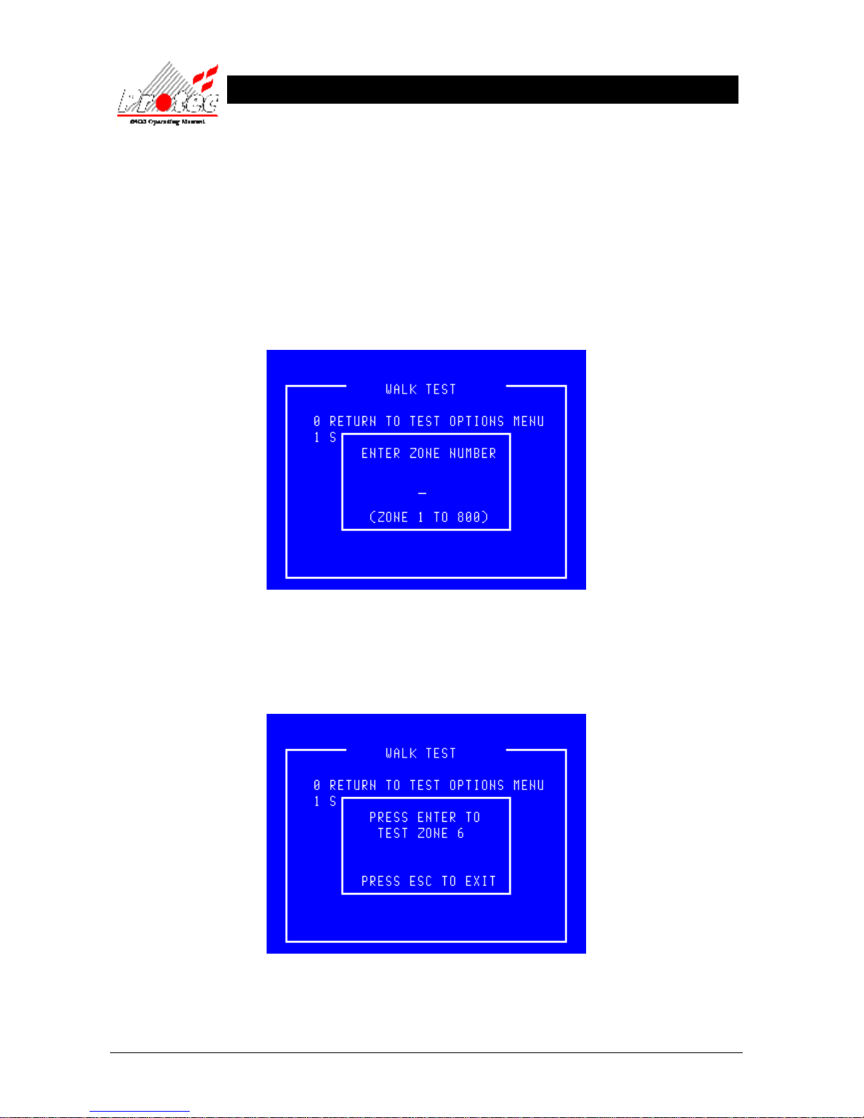
93-310-10 Issue 4 Rev 5 Page 54 of 88 Copyright Protec Fire Detection PLC
6400 OPERATING MANUAL
9.4.1 WALK TEST ZONE
• Function : This option allows the operator to test the loop devices within a single zone without the need to
return to the control panel to silence and reset the fire event. When a device is tested the panel
activates the ‘alarm outputs’ that are programmed for the device under test for a predetermined
period (set by the engineer during commissioning), then the ‘alarm outputs’ are turned off. Note
that the rest of the system will continue to operate as a standard fire alarm system.
• Outputs : Note that only the alarm outputs on the node on which the device is activated will sound (assuming
that the engineer option to disable outputs during test is not in use).
• Selecting Option : To select this option press the ‘1’ key while in the ‘Walk test’ menu.
• Select a zone : The menu will accept a zone number between 1 and 800 inclusive. Zones greater than 100
are only used on an expanded system. Once a zone has been selected the system checks
whether this zone is already in test mode and either offers the opportunity to test the
selected zone as shown below or cancels the zone testing immediately. It can cancel
immediately because only one zone at a time is permitted to be tested.
• Zone walk test : To confirm the zone test mode press the ‘Enter’ key.
• Exiting Option : To cancel the zone disablement press the ‘Esc’ key.
Page 55
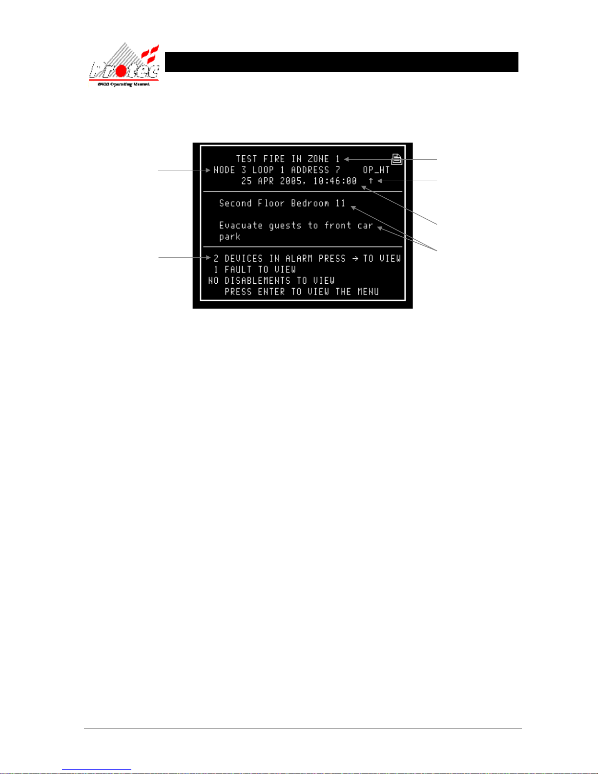
93-310-10 Issue 4 Rev 5 Page 55 of 88 Copyright Protec Fire Detection PLC
6400 OPERATING MANUAL
• Testing Loop : Once the ‘Zone walk test’ has been selected, the Loop devices in that zone can then be
tested. When a device is activated, the screen will display the following information and
then reset automatically :-
Any Alarm Outputs (Programmed) will activate with the exception of those programmed for
coincidence (assuming that the engineer option to disable outputs during test is not in use).
After predetermined time ( programmed by the Engineer and displayed in section 9.4 ) all outputs
will deactivate and the display will then return to the previous menu.
Displays the Node /
Loop & address location
of the device in alarm
Note - If text has been
assigned to the node, then the
text will be displayed rather
than the node & loop No
Location of device that has
alarmed (only if specified).
Displays the ‘Zone’ number in
which the fire has occurred
Displays the date & time of
the activation
Displays the number of
Devices which are currently
in an alarm condition
The arrow indicates the
sensor that has generated
the fire signal.
Page 56
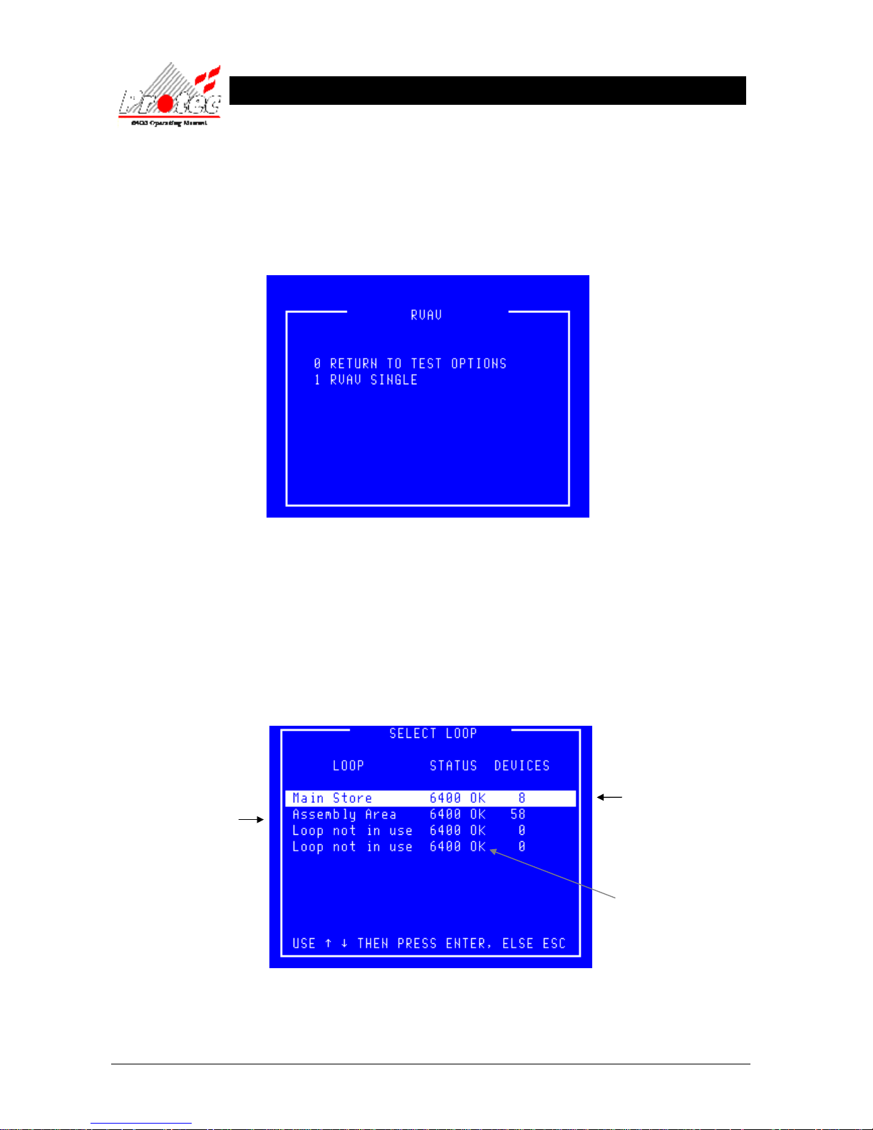
93-310-10 Issue 4 Rev 5 Page 56 of 88 Copyright Protec Fire Detection PLC
6400 OPERATING MANUAL
9.5 RVAV (Remote Visual Address Verification)
• Function : This option allows the user to visually verify the address of a device on any ‘6000’ series
loop.
• Selecting Option : To select this option press the ‘4’ key while in the ‘Test Options’ menu. The following
menu will be displayed :-
• Exiting Option : To exit the ‘RVAV’ menu and return to the ‘Test Options’ menu press the ‘0’ or ‘Esc’ key.
9.5.1 RVAV SINGLE
• Function : This option allows the user to visually verify the address of a device on a loop.
• Selecting Option : To select this option press the ‘1’ key while in the ‘RVAV’ menu. The following menu
will be displayed.
Displays the Node and
Loop Number
or a text description if
the option has been
specified.
Indicates the Loop status.
6400 ok = Loop healthy.
Displays No of devices logged
onto the loop.
Page 57
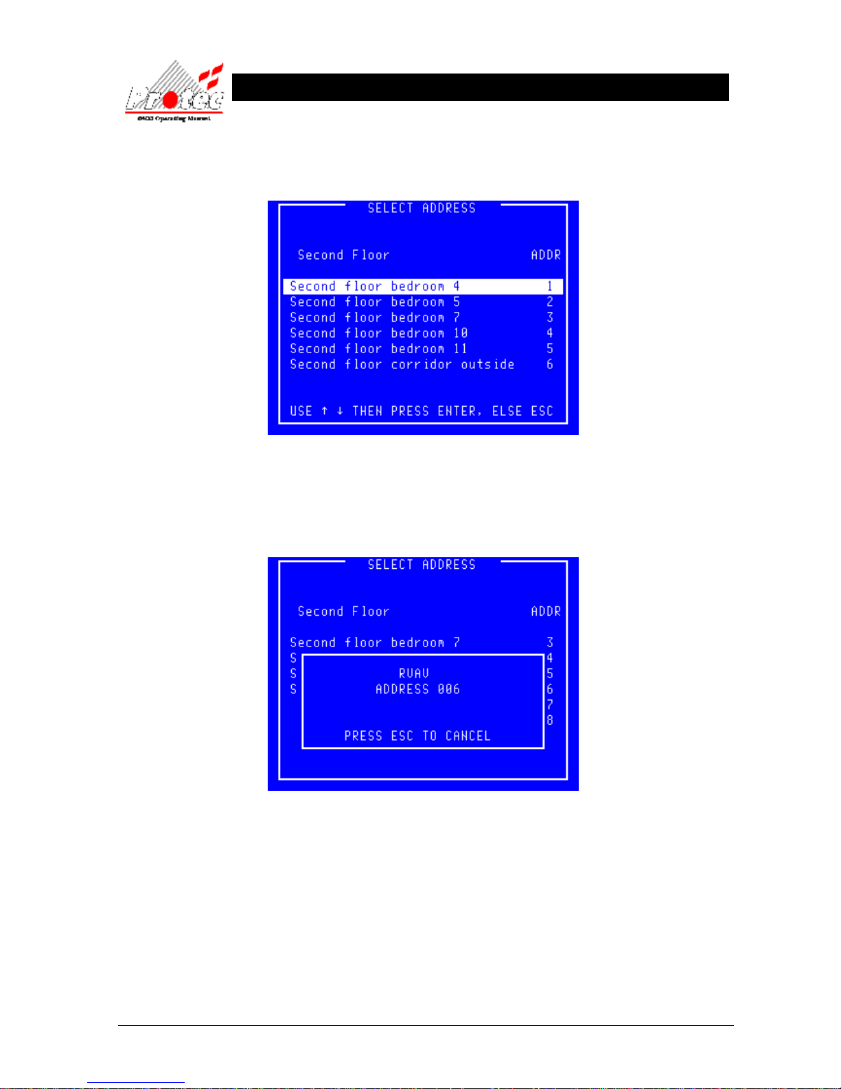
93-310-10 Issue 4 Rev 5 Page 57 of 88 Copyright Protec Fire Detection PLC
6400 OPERATING MANUAL
• Loop Selection : Use the highlight bar to select the ‘Node & Loop’ number for which a device is to
be visually checked and then press the ‘ENTER’ key. Note that only ‘6000’ series loops
support RVAV. Once selected the panel will display the following menu :-
• Exiting Option : To EXIT the ‘RVAV Single’ menu and return to the ‘RVAV’ menu press the ‘0’ or
‘Esc’ key.
• Select Address : Use the highlight bar to select the address to test then press the ‘Enter’ key. A box will appear
on the display as shown below :-
• Exiting Option : To stop the ‘RVAV’ and return to the ‘Select address’ menu press the ‘Esc’ key.
• Warning : During RVAV a device cannot generate a fire signal.
• Timeout : The RVAV will timeout after 10 minutes if ‘Esc’ has not been pressed.
Page 58
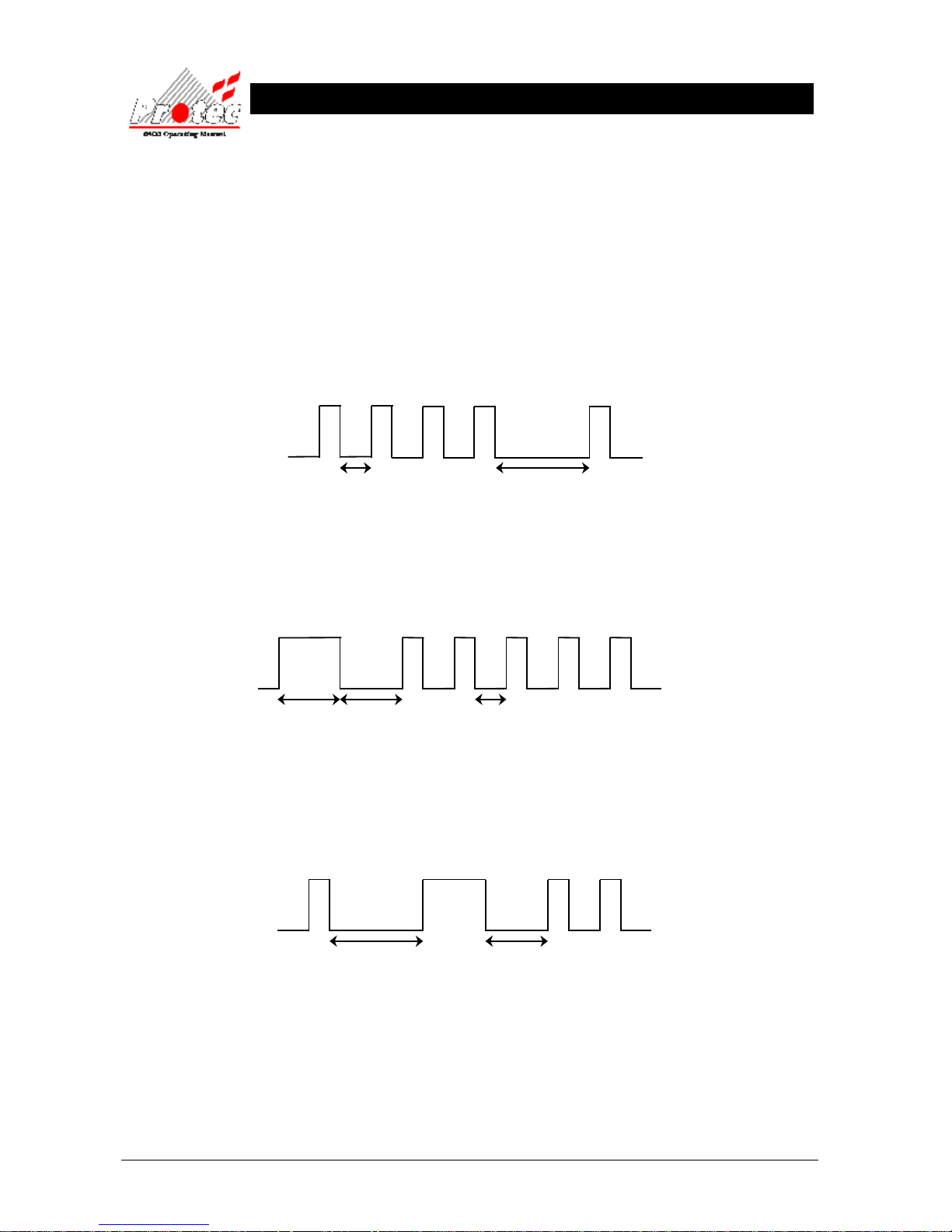
93-310-10 Issue 4 Rev 5 Page 58 of 88 Copyright Protec Fire Detection PLC
6400 OPERATING MANUAL
9.5.2 RVAV DESCRIPTION
• Availability : RVAV is available on loop devices that have a ‘Fire LED’.
• Format : When the device receives the signal to RVAV, it outputs its address in the following format :-
The address is output as hundreds, tens and units with a one and a half second delay between.
If the address is less than 100 then the leading zero for the hundreds is not output. The address
is determined by counting the LED flashes. A zero is denoted by a long flash of approximately
one second. There is a half second delay (approx) between LED flashes.
Address 41
• Address 05
• Address 102
1 second
ON
OFF
0.5 seconds
ON
OFF
0
1 + 1 + 1 + 1 + 1 = 05
1
0
1 + 1
= 102
ON
OFF
0.5 seconds
1 + 1 + 1 + 1 1 = 41
1.5 seconds
Note : The delay following a zero is
reduced to one second
Fire LED State
Fire LED State
1 second
See Note below
1 second1.5 seconds
Fire LED State
Page 59
93-310-10 Issue 4 Rev 5 Page 59 of 88 Copyright Protec Fire Detection PLC
6400 OPERATING MANUAL
T
T
E
E
X
X
T
T
E
E
D
DII
T
T
O
O
R
R
10.1 TEXT EDITOR
To select the ‘Text Editor ’ Menu, select ‘6’ from the ‘Main Menu’ options.
Once selected, the display will show the following :-
Note
The standard user access permits viewing of the loop device text but does not permit editing. Users trained and
authorised to make changes to the system configuration are supplied with an alternative ‘Exchange’ code. Use of this
alternative code modifies option ‘1’ to read ‘EDIT LOOP DEVICE TEXT’.
The following menus assume that the user can edit the text. Users who are not permitted to edit the text will find that
the option to make and save changes is not available.
For further details
Refer to section 10.2
Page 60

93-310-10 Issue 4 Rev 5 Page 60 of 88 Copyright Protec Fire Detection PLC
6400 OPERATING MANUAL
10.2 EDIT LOOP DEVICE TEXT
• Function : This option allows the user to view or edit the ‘Location text’ for any loop device on the
system.
• Selecting Option : To select this option press ‘1’ key while in the above text editor menu.
Once selected, the LCD will display ‘Select Loop’ menu :-
• Select Loop : Use the High-light bar to select the Node & Loop number of the device to be edited
and then press the ENTER key. Once selected the panel will request data from the Node,
while the data is being requested , the display will show the following message :-
Displays No of devices
logged onto each loop.
Page 61
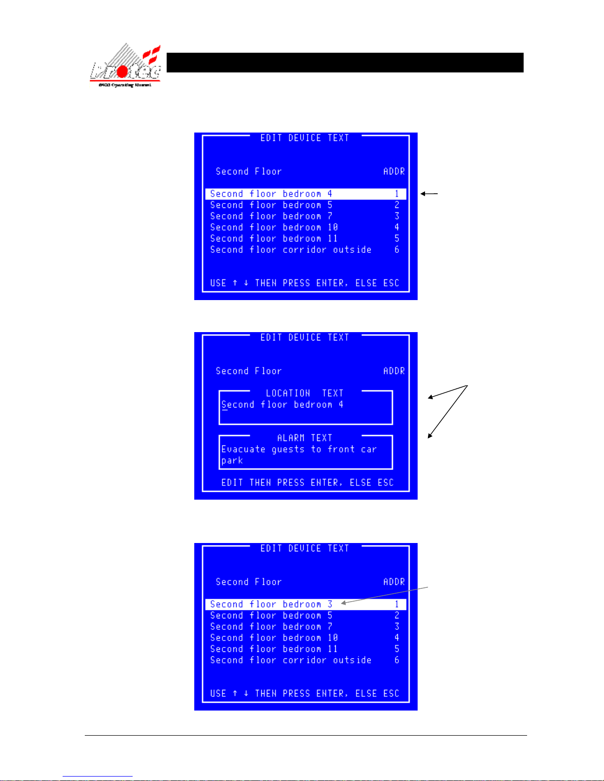
93-310-10 Issue 4 Rev 5 Page 61 of 88 Copyright Protec Fire Detection PLC
6400 OPERATING MANUAL
Once all the data has been received from the Node, the following ‘Edit device text’ screen
will be displayed.:-
Pressing the ENTER key will then display the ‘Edit device text’ display :-
Once the Text has been edited correctly, press the ENTER button.
This will then display the ‘Edit device text’ menu with the NEW alterations.
Use the Highlight bar
to select the device for
editing. and then press
ENTER key.
Use the ← ↑ ↓ →
keys to move the cursor
and the keyboard to edit
the text info.
The text alterations will
now be displayed
Page 62
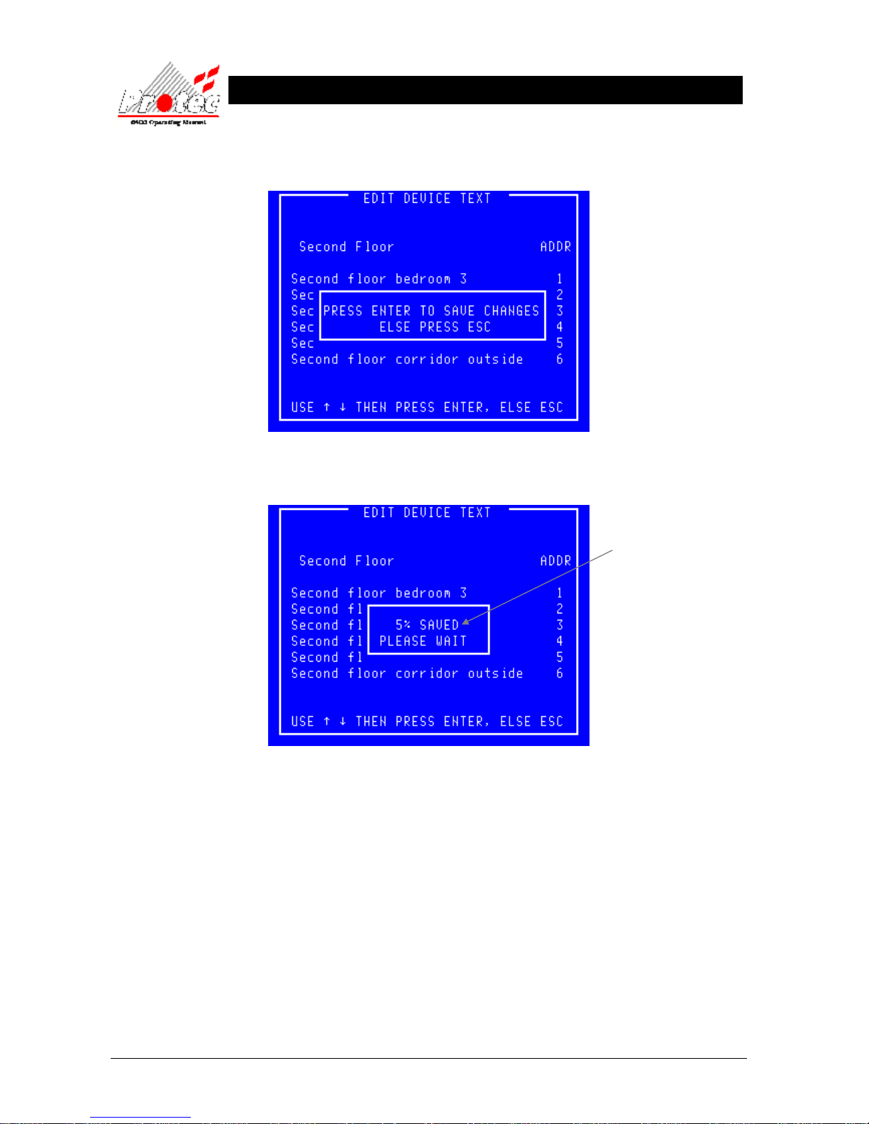
93-310-10 Issue 4 Rev 5 Page 62 of 88 Copyright Protec Fire Detection PLC
6400 OPERATING MANUAL
If further alterations are required then move the highlight bar to select a new device and press the
ENTER key. To exit press the ESC button. The display will show :-
• Exiting Option : To abandon the changes press the ‘Esc’ key.
• Saving Data : Press the ENTER Key to save the above changes to memory. The display will show :-
Once all the new alterations have been saved to memory, the LCD returns back to
the ‘Text Editor Menu’ options.
Indicates the percentage
saved to memory. This is
approximate and typically
completes after 40 to 60%
Page 63

93-310-10 Issue 4 Rev 5 Page 63 of 88 Copyright Protec Fire Detection PLC
6400 OPERATING MANUAL
C
CLL
E
E
A
A
R
R
S
S
Y
Y
S
S
T
T
E
E
M
M
F
F
A
A
U
ULL
T
T
11.1 CLEAR SYSTEM FAULT
Each DCN on the network has a ‘SYSTEM FAULT’ warning lamp. This fault is latching, and will occur after a
complete system failure either due to a prolonged or full power down of the panels microprocessor.
Selecting option ‘7’ ‘Clear system fault’ from the ‘Main menu’ options, will extinguish the ‘SYSTEM FAULT’ LED
on all nodes.
Page 64
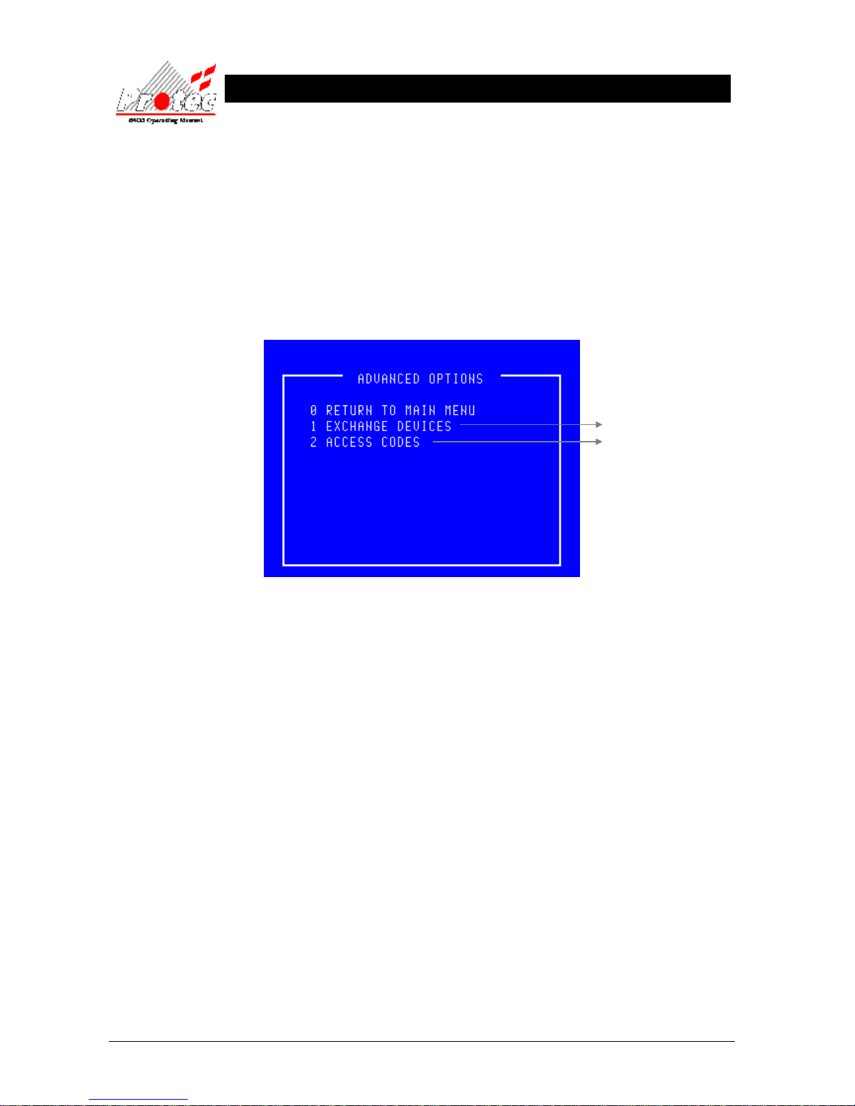
93-310-10 Issue 4 Rev 5 Page 64 of 88 Copyright Protec Fire Detection PLC
6400 OPERATING MANUAL
A
A
D
D
V
V
A
A
N
N
C
C
E
E
D
D
O
O
P
P
T
TII
O
O
N
N
S
S
12.1 ADVANCED OPTIONS
• Function : This menu permits the ability to swap loop devices for cleaning and also allows the
‘master’ user to set up individual codes for other users.
• Selecting Option : To select this option press the ‘8’ key while in the ‘Main menu’.
Once selected, the LCD will display the advanced options menu shown below :-
• Exiting option : To exit the advanced options menu press the ‘0’ or ‘Esc’ key.
• Access Codes : This option is only available when the ‘master’ user code has been entered.
• Exchange Devices : This option is available when the ‘Exchange’ user code’ has been entered. It is only
applicable to ‘6000’ series loops. On 6400 systems driving other loop devices ‘Access
Codes’ becomes option ‘1’.
For further details
Refer to section 12.2
Refer to section 12.3
Page 65
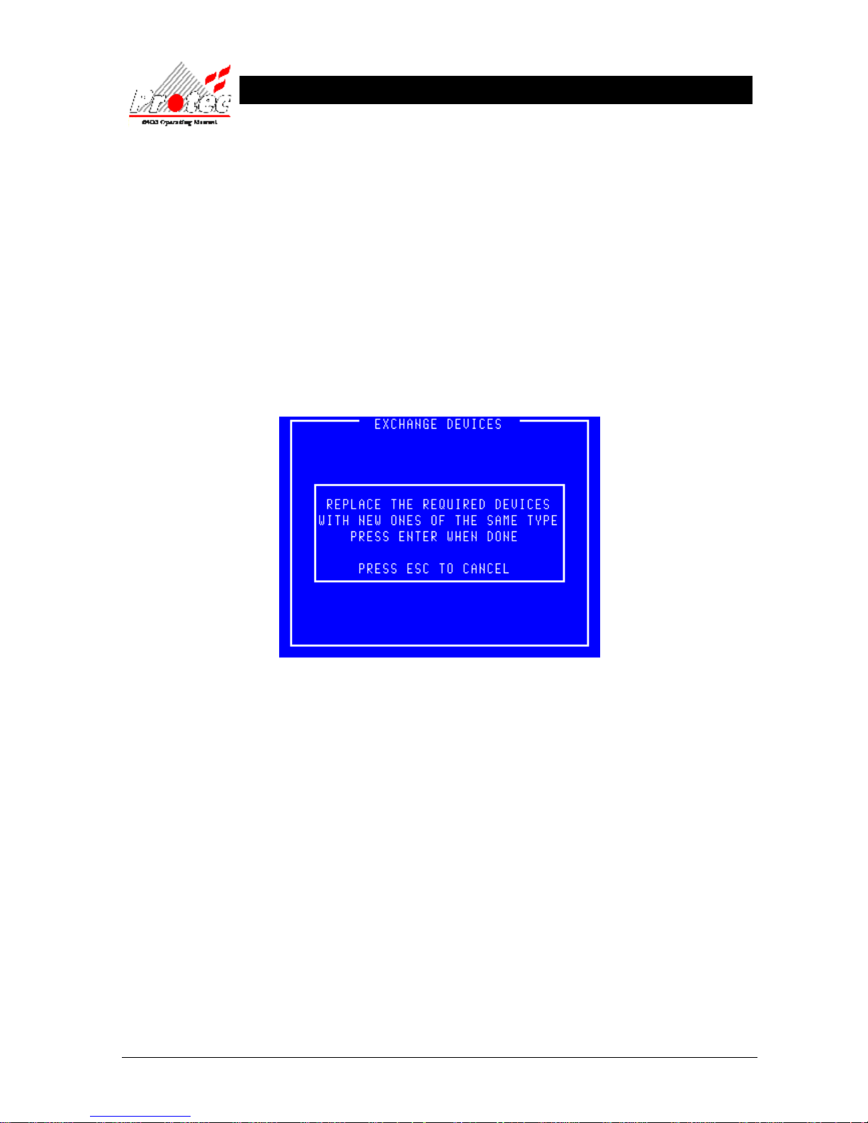
93-310-10 Issue 4 Rev 5 Page 65 of 88 Copyright Protec Fire Detection PLC
6400 OPERATING MANUAL
12.2 EXCHANGE DEVICES
• Function : This option permits the swapping of up to eight devices (addresses) per loop, typically for
cleaning. No device must be exchanged prior to selecting this menu otherwise a fire signal
may be generated.
• Device type : Each device must be swapped for one of the same type.
• 16 Way Board : The 16 Way Board occupies 16 addresses therefore this has to be exchanged in stages i.e.
no more than 8 addresses at a time. Before exchanging a 16 Way Board make a note of all
16 device serial numbers for the old and the new boards to ensure that the address numbers
are exchanged correctly.
• Selecting Option : To select this option press the ‘1’ key while in the ‘Advanced Options’ menu’.
Once selected, the LCD will display the exchange devices screen as shown below :-
• Exiting option : To exit the ‘Exchange devices’ menu and return to the ‘Advanced options’ menu press the
‘Esc’ key.
• Exchange rules : Once the exchange screen is displayed the user may then swap devices.
1) It is important to record the node, loop, address and serial number of the
device(s) being removed and those of the device(s) being fitted because this
information will need to be referred to later.
2) A disabled device cannot be exchanged because although it will have been
removed it will not have recorded by the system as missing.
3) The newly exchanged device will turn its fire led on to signify that the 6400
system has found it.
Do not proceed beyond this point until the device(s) have been exchanged.
Page 66
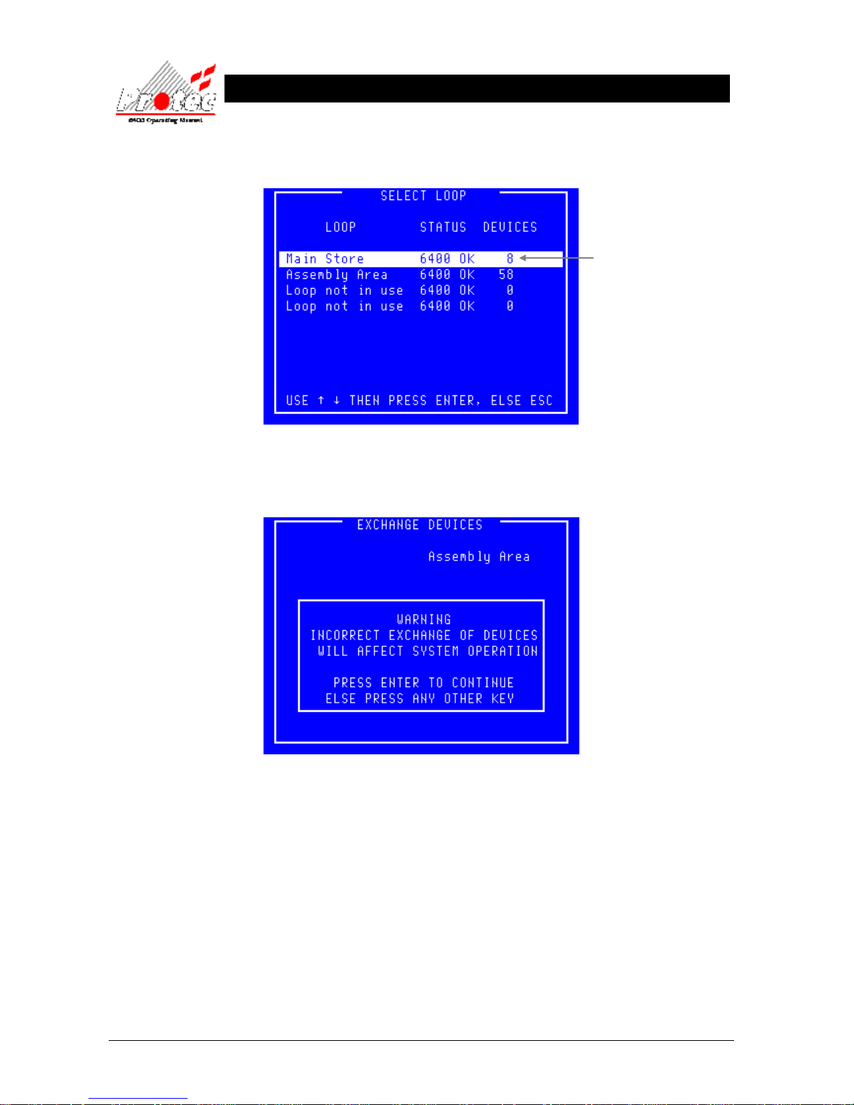
93-310-10 Issue 4 Rev 5 Page 66 of 88 Copyright Protec Fire Detection PLC
6400 OPERATING MANUAL
• Selecting Option : To select this option press the ‘Enter’ key while the display shows the exchange screen.
Once selected, the LCD will display the ‘Select Loop’ menu :-
• Select Loop : Use the High-light bar to select the Node & Loop number of the device(s) that have been
exchanged, then press the ‘Enter’ key. Once selected the display will show the following
warning message :-
• Warning : It is important users appreciate that mistakes made when exchanging could lead to
serious problems such as the incorrect location being reported for a fire alarm.
Displays No of devices
logged onto each loop.
Page 67
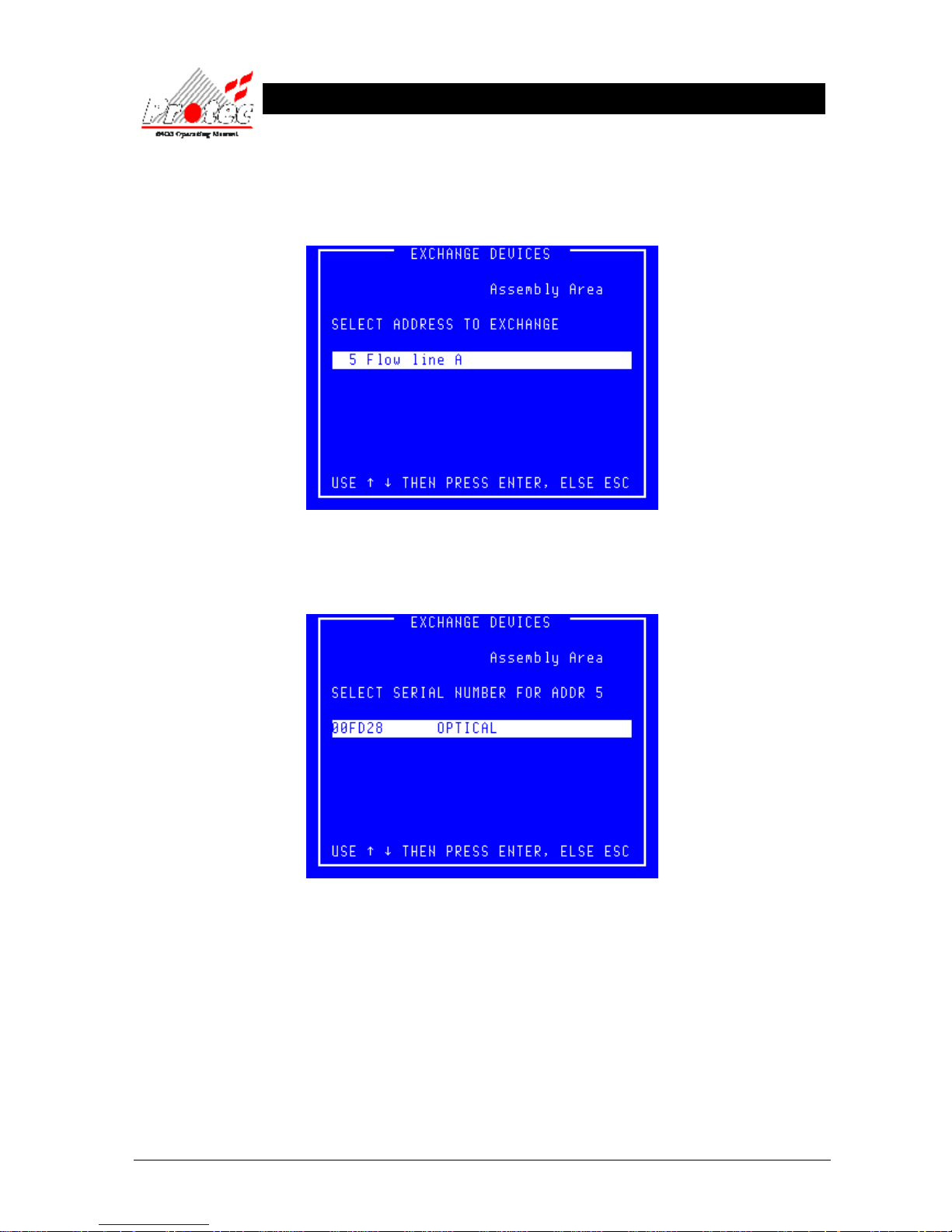
93-310-10 Issue 4 Rev 5 Page 67 of 88 Copyright Protec Fire Detection PLC
6400 OPERATING MANUAL
• Exiting option : To exit from this menu press the ‘Esc’ key.
• Proceed : Press ‘Enter’ to accept the warning and proceed with the exchange. The display will list all
the addresses from which a device is missing as shown below :-
• Exiting option : To exit from this menu press the ‘Esc’ key.
• Address select : Use the highlight bar to select one of the addresses then press ‘Enter’.
• Exiting option : To exit from this menu press the ‘Esc’ key.
• Device select : Use the highlight bar to select the serial number of the device that was exchanged at the
selected address then press ‘Enter’.
Page 68
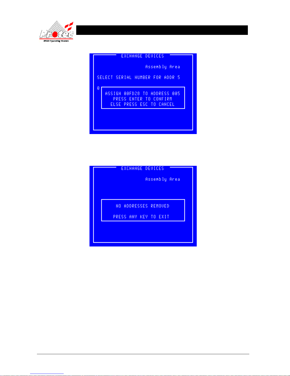
93-310-10 Issue 4 Rev 5 Page 68 of 88 Copyright Protec Fire Detection PLC
6400 OPERATING MANUAL
• Exiting option : To cancel the exchange press the ‘Esc’ key.
• Device select : Press ‘Enter’ to confirm the details of the exchange.
• Exiting option : To exit from this menu press the ‘Esc’ key.
Page 69
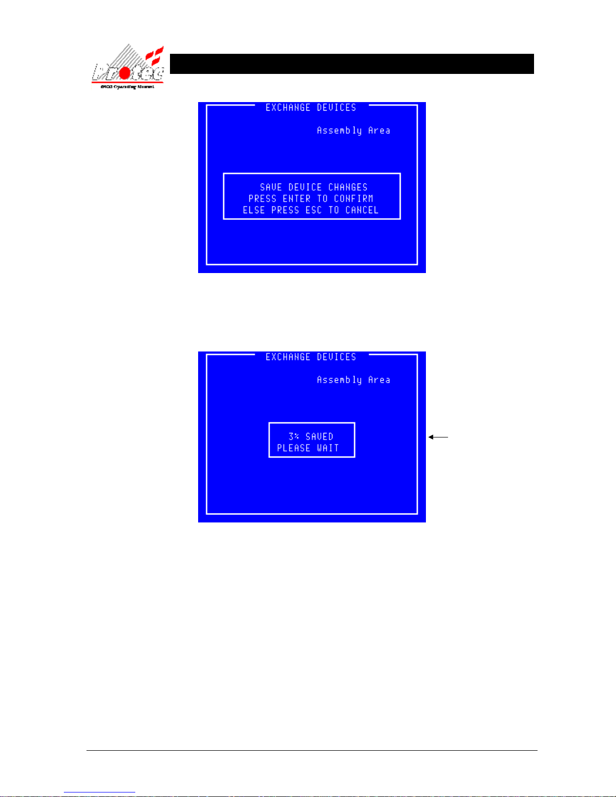
93-310-10 Issue 4 Rev 5 Page 69 of 88 Copyright Protec Fire Detection PLC
6400 OPERATING MANUAL
• Exiting option : To exit from this menu press the ‘Esc’ key.
• Confirm exchange : Press ‘Enter’ to go ahead and save the new data
• Exiting option : Once the new device data has been saved the menu will automatically exit back to the
‘Advanced options’ menu.
• Device Test : On completion of the exchange, each exchanged device must be tested to ensure that the
newly installed devices are operating correctly.
Indicates the percentage
saved to memory. This figure
is approximate and typically
completes after 40 to 60%.
Page 70
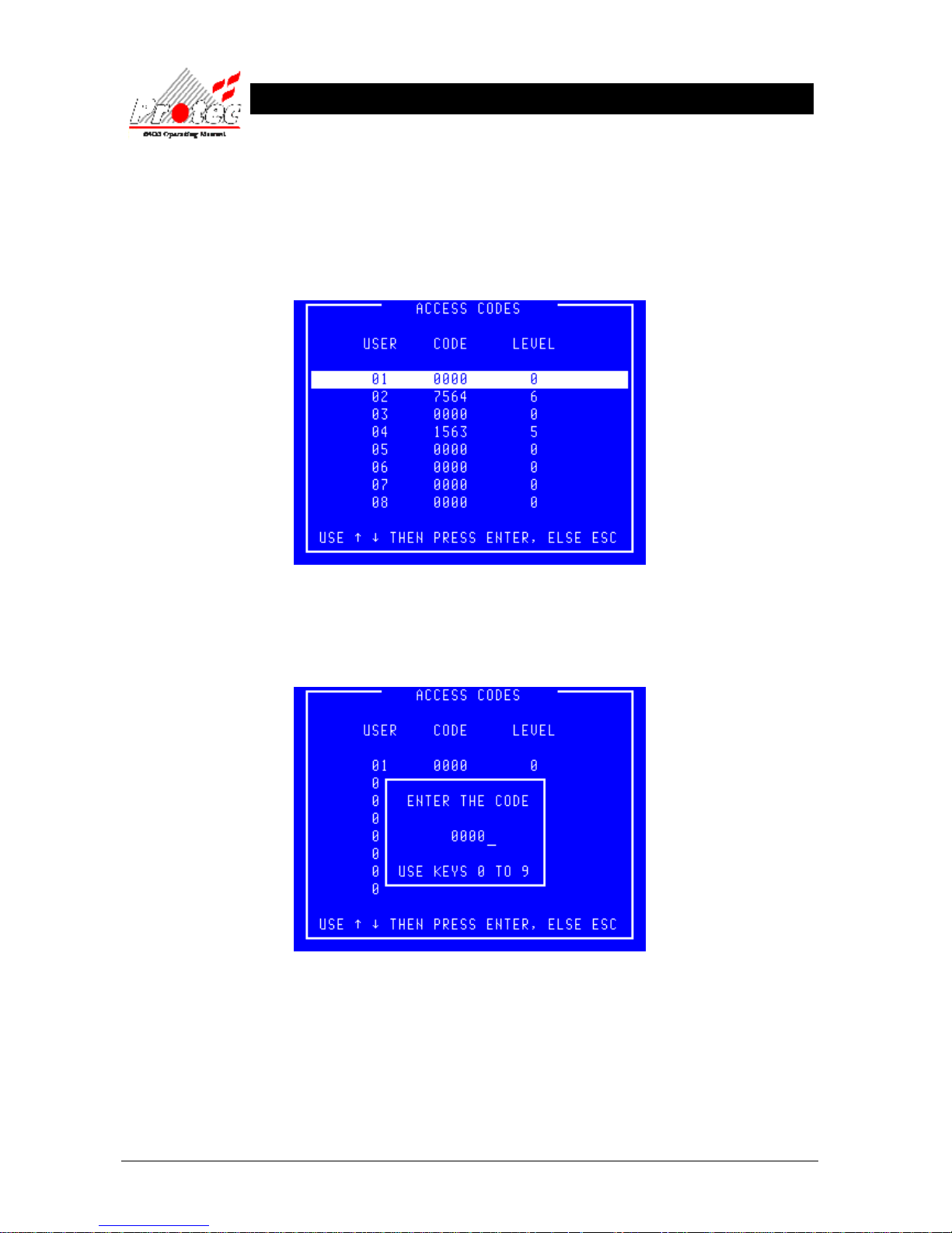
93-310-10 Issue 4 Rev 5 Page 70 of 88 Copyright Protec Fire Detection PLC
6400 OPERATING MANUAL
12.3 ACCESS CODES
• Function : This option allows the ‘master’ user to set up to 32 individual codes for other users. This
menu option is offered only when the ‘chief’ user code has been entered.
• Selecting Option : To select this option press the ‘2’ key while in the ‘Advanced Options’ menu’.
Once selected, the LCD will display the user code menu as shown below :-
• Exiting option : To EXIT the ‘User Codes’ menu and return to the ‘Main menu’ press the ‘ESC’ key.
• Selecting a code : Select a code to allocate by moving the highlight bar over the chosen code number and
press the Enter key. A box will appear on the display as shown below :-
• Exiting option : To abandon the allocation of a code and return to the ‘User codes’ menu press the Esc
key.
• Allocating a code : Use the ‘←’ to delete the previous code then enter the new code using the keys ‘0’ to ‘9’.
Press the Enter key when complete and the display will offer the opportunity to set the
level. Entering the code ‘0000’ removes an allocated code.
Page 71
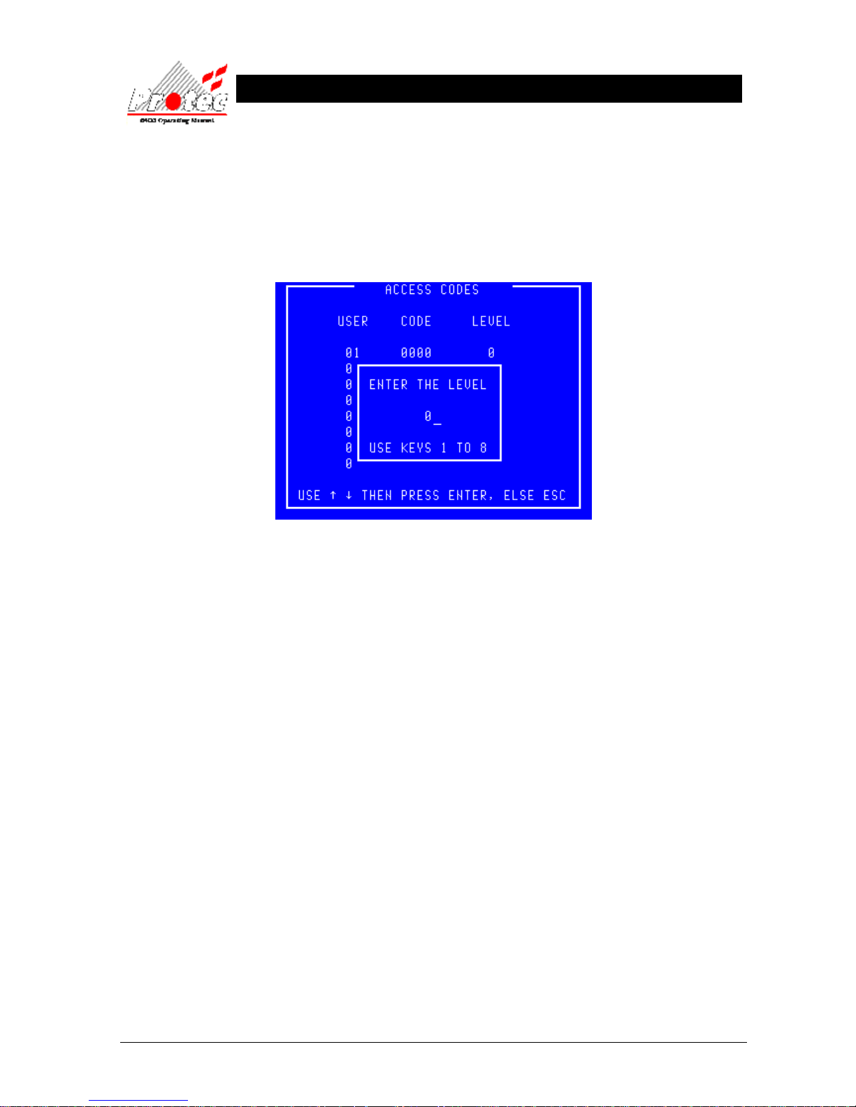
93-310-10 Issue 4 Rev 5 Page 71 of 88 Copyright Protec Fire Detection PLC
6400 OPERATING MANUAL
• Levels : Individual users can be restricted in their use of the system by allocating a level to their
code. A level of ‘1’ implies that only menu option ‘1’ of the ‘Main menu’ will be offered to
that user when the code is input. Level ‘2’ implies menu options ‘1’ and ‘2’ of the ‘Main
menu’ etc. A level of ‘0’ is used when the code is ‘0000’.
• Allocating a level : Use the ‘←’ to delete the previous level then enter the new level using the keys ‘1’ to ‘7’.
Press the Enter key when complete and the display will return to the ‘User codes’ menu.
• Exiting option : To abandon the allocation of a level and to return to the ‘User codes’ menu press the ‘Esc’
key.
Page 72
93-310-10 Issue 4 Rev 5 Page 72 of 88 Copyright Protec Fire Detection PLC
6400 OPERATING MANUAL
R
R
E
E
F
F
E
E
R
R
E
E
N
N
C
C
E
E
13.1 THRESHOLD LEVELS FOR 6000 SERIES ANALOGUE DEVICES
ANALOGUE THRESHOLD LEVELS (T
hist
)
FAULT NORMAL
OPTICAL SMOKE SENSOR
0 – 15, 141 – 255 16 – 140
IONISATION SMOKE SENSOR
0 – 15, 151 – 255 16 – 150
TEMPERATURE SENSOR
0 – 25, 250 – 255 26 – 249
OPTICAL HEAT SENSOR – Optical channel
0 – 15, 141 - 255 16 – 140
OPTICAL HEAT SENSOR – Heat channel
0 – 25, 250 – 255 26 – 249
CO HEAT SENSOR – CO channel
0 – 19, 151 - 255 20 - 150
CO HEAT SENSOR – Heat channel
0 – 24, 251 - 255 25 – 250
OPTICAL HEAT CO SENSOR – Optical channel
0 – 34, 91- 255 35 – 90
OPTICAL HEAT CO SENSOR – Heat channel
0 – 24, 251 - 255 25 – 250
OPTICAL HEAT CO SENSOR – CO channel
0 – 19, 151 - 255 20 - 150
13.2 THRESHOLD LEVELS FOR 6000 SERIES DIGITAL DEVICES
THRESHOLD LEVELS (T1)
SENSITIVITY FAULT NORMAL FIRE
MCP
N/A 0 85 220
ZONE ALARM INTERFACE
N/A 17 - 22 85 219 - 220
MICCO
N/A 17 - 18 85 220
SOUNDERS & OTHER OUTPUT DEVICES
N/A 0 85 N/A
Notes :-
1. T
hist
is shown on the analogue value
graph (see section 9.3).
2. Fire levels are calculated by
algorithms within the system (see
section 9.3). These fire levels change
with the device sensitivity.
3. Each channel of a multi-channel
device such as the Optical heat has
the same sensitivity.
Page 73
93-310-10 Issue 4 Rev 5 Page 73 of 88 Copyright Protec Fire Detection PLC
6400 OPERATING MANUAL
13.3 THRESHOLD LEVELS FOR 5000 SERIES DEVICES
ANALOGUE THRESHOLD LEVELS
SENSITIVITY FAULT NORMAL PRE-ALARM FIRE
‘N/S’ TYPE ‘0’ ( MCP , SOUNDER or INTERFACE )
Low 0 - 80 81 - 192 N / A 193 - 255
Medium 0 - 80 81 - 192 N / A 193 - 255
High 0 - 80 81 - 152 153 - 192 193 - 255
‘ION’ TYPE ‘1’ ( IONISATION SMOKE SENSOR )
Low 0 - 8 9 - 152 153 - 208 209 - 255
Medium 0 - 8 9 - 152 153 - 184 185 - 255
High 0 - 8 9 - 152 N / A 153 - 255
‘HEAT’ TYPE ‘2’ ( TEMPERATURE SENSOR )
Low 0 1 – 220 N/A 221 – 255
Medium ( 68º ) 0 1 – 196 N/A 197 – 255
High 0 1 - 168 N/A 169 - 255
‘OPT’ TYPE ‘3’ ( OPTICAL SENSOR )
Low 0 1 – 160 161 - 200 201 - 255
Medium 0 1 – 128 129 - 168 169 – 255
High 0 1 - 112 113 - 136 136 – 255
13.4 THRESHOLD LEVELS FOR 4000 SERIES DEVICES
ANALOGUE THRESHOLD LEVELS
SENSITIVITY FAULT NORMAL PRE-ALARM FIRE
MCP
Medium 0-15, 17-63 16 N / A 64-127
IONISATION SMOKE SENSOR , TEMPERATURE SENSOR, OPTICAL SENSOR, MULTISENSOR
Medium 0-9 10-40 41-50 51-127
Page 74
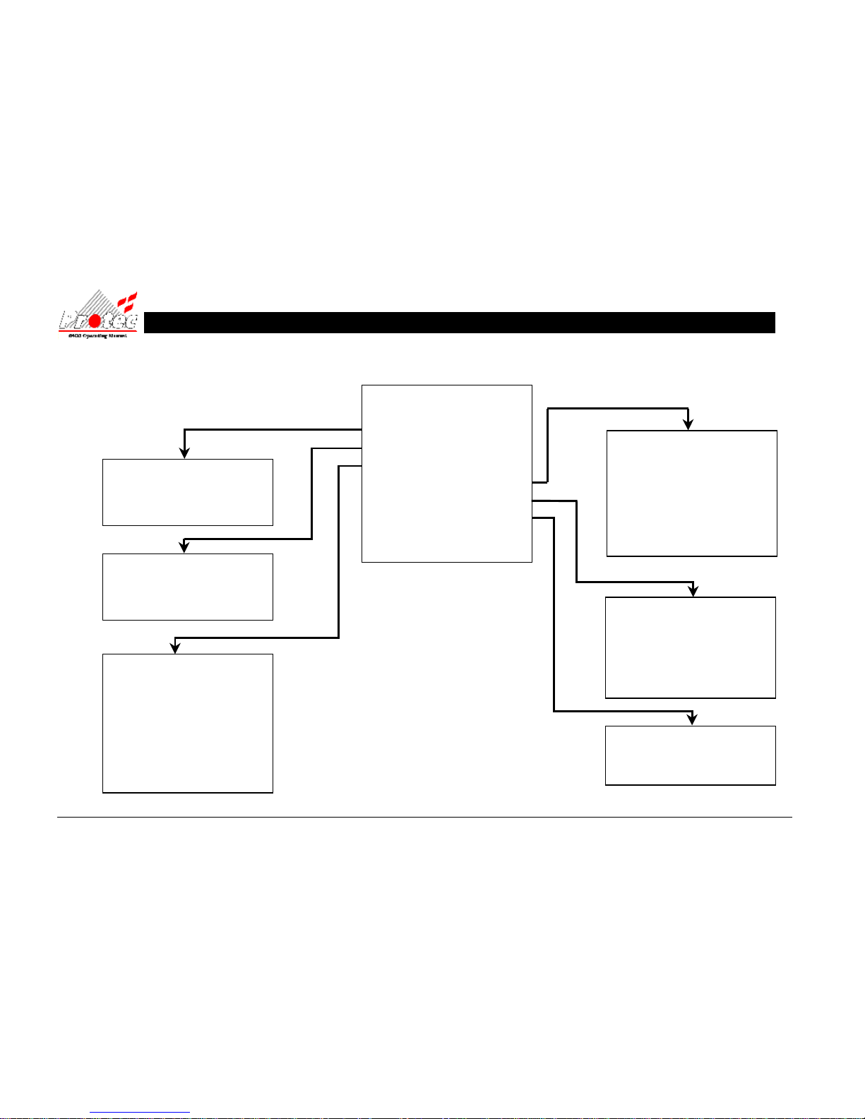
93-310-10 Issue 4 Rev 5 Page 74 of 88 Copyright Protec Fire Detection PLC
MAIN MENU
0 Exit from main menu
1 Set time / date
2 Display events
3 Printer menu
4 Disablement menu
5 Test options
6 Text editor menu
7 Clear system fault
13.5 OPERATING MENU FLOWCHART
(1) SET TIME / DATE
0 Return to main menu
1 Set date
2 Set time
(3) PRINTER MENU
0 Return to main menu
1 Current faults
2 Current disablements
3 Print past events
4 Print Analogue values
5 Print address S/N
6 Print high analogue values
7 Cancel printing
(2) DISPLAY EVENTS
0 Return to main menu
1 Display Past Fires
2 Display Past Faults
(4) DISABLEMENT MENU
0 Return to main menu
1 Device disable / normalise
2 No disablements to view
3 Zone disable / normalise
4 Output disablement menu
5 Change to address disable
6 Disable Output Delay
(6) TEXT EDITOR
0 Return to main menu
1 View loop device text
(5) TEST OPTIONS
0 Return to main menu
1 Lamp test
2 View analogue values
3 Walk Test Menu
4 RVAV
Page 75
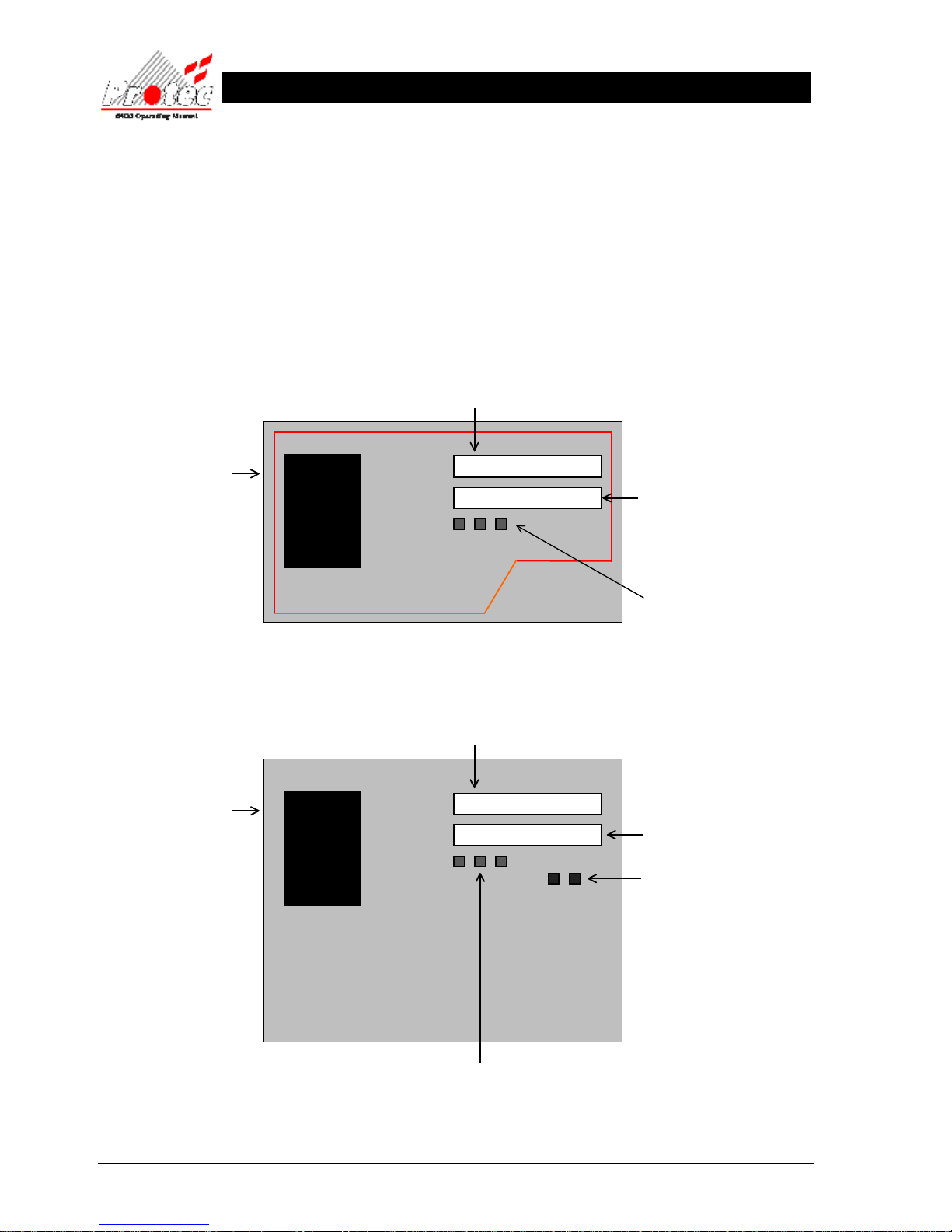
93-310-10 Issue 4 Rev 5 Page 75 of 88 Copyright Protec Fire Detection PLC
6400 OPERATING MANUAL
N
N
E
E
T
T
W
W
O
O
R
R
K
K
R
R
E
E
P
P
E
E
A
A
T
T
P
P
A
A
N
N
E
E
L
L
S
S
14.1 NETWORK LCD PANEL - (No network controls)
14.2 RDN PANEL – (With network controls)
FIGURE 1
FIRE
Power
On
Location / Alarm Text
LCD
Indications
System Status
Function Buttons
Menu /Select / Mute
Disablement
Fault
6400
Fire Alarm Repeat Display
FIGURE 2
FIRE
Power
On
Location / Alarm Text
LCD
Indications
System Status
Function Buttons
Menu /Select / Mute
Fault
Disablement
Control Buttons
Silence / Reset
6400
Fire Alarm Repeat Display
Page 76
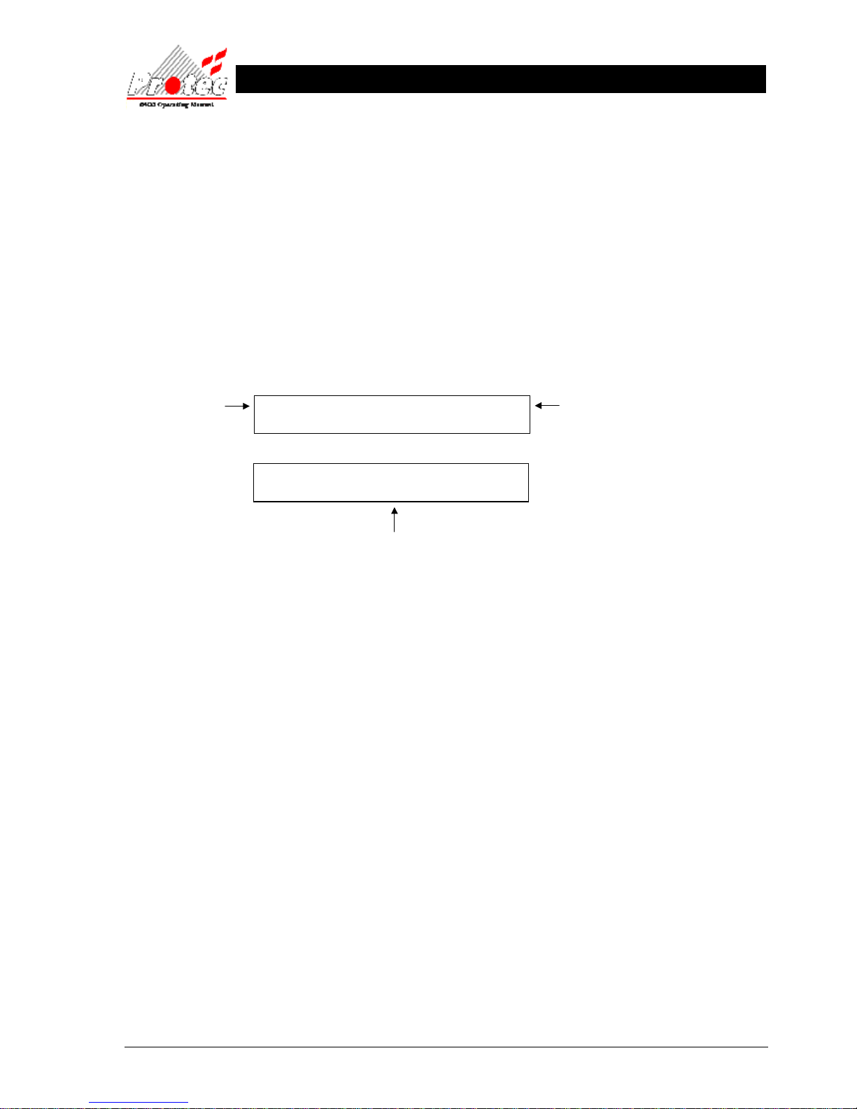
93-310-10 Issue 4 Rev 5 Page 76 of 88 Copyright Protec Fire Detection PLC
6400 OPERATING MANUAL
N
N
E
E
T
T
W
W
O
O
R
R
K
K
L
L
C
C
D
D
D
DII
S
S
P
P
L
L
A
A
Y
Y
15.1 NETWORK LCD DISPLAY
The following will be displayed when the system is in a ‘Normal’ condition, i.e. no fires or faults: -
System Normal 30 May 2006, 10:17
PROTEC FIRE DETECTION PLC
Current time & date
System status
Location text remains blank
( Not Illuminated)
Page 77

93-310-10 Issue 4 Rev 5 Page 77 of 88 Copyright Protec Fire Detection PLC
6400 OPERATING MANUAL
F
F
U
U
N
N
C
C
T
TII
O
O
N
N
B
B
U
U
T
T
T
T
O
O
N
N
S
S
16.1 - FUNCTION BUTTONS
On the front of a repeat panel, there are 5 function buttons (only 3 on the LCD panel) as follows: -
MENU SELECT MUTE
SILENCE RESET
(Only available on the RDN)
Menu Button - Pressing this button allows access to the Repeat panels ‘Menu options’ (refer to Section 16.1 for
details).
Select Button - This button is primarily used when in the ‘Menu options’.
Mute - This button will stop the fault / fire buzzer on the Repeat panel only.
Silence - Pressing this button will silence any currently active ‘ALARMS’.
Reset - Pressing this button will reset any active fire events on the network. This button will only function
once the alarms have been silenced
Page 78
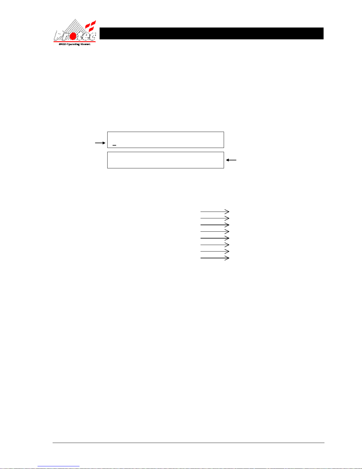
93-310-10 Issue 4 Rev 5 Page 78 of 88 Copyright Protec Fire Detection PLC
6400 OPERATING MANUAL
Location text screen shows the software
version number and panel set up
Menu option
for selection
M
M
E
E
N
N
U
U
O
O
P
P
T
TII
O
O
N
N
S
S
17.1 MENU OPTIONS
The Repeat Panel has a number of ‘Menu options’ available to the user. To access these menu options, press the
‘MENU’ button on the front of the panel. Once selected, the panel will show the following on the displays: -
• Viewing options : Pressing the ‘MUTE’ button will increment through the menu options as listed:-
For further details refer to
View current fires / alarms Section 18
View current faults* Section 21
View current disablements* Section 22
Print current fires / alarms* Section 23
Print current faults* Section 23
Print current disablements* Section 23
Lamptest Section 24
Abort Printout Section 25
* Only available if the repeat panel is configured accordingly.
• Selecting option : When the option required is shown on the upper LCD, press the ‘SELECT’ button to
choose the option.
• Exiting option : To exit the ‘Menu options’ and return to a normal screen, press the ‘MENU’ button.
17.2 MENU VIEWING INSTRUCTIONS
Menu Button : This button is used to enter the menus from the normal display. Once within the menu structure
pressing this button moves the user back one level.
Select Button : When in menus, this button will select the option currently shown on the upper LCD by a
flashing cursor.
Mute Button : In menus, pressing this button will cycle through the available menu options.
MENU OPTIONS :-
VIEW CURRENT FIRES / ALARMS
SW:V3.37 Node : 8 Pnl-type : 7
Srl : B0000001 FG : 0 Lnk : N=0 L=0 Net : 1
Page 79
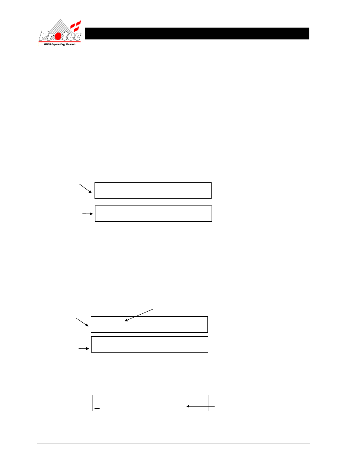
93-310-10 Issue 4 Rev 5 Page 79 of 88 Copyright Protec Fire Detection PLC
6400 OPERATING MANUAL
V
VII
E
E
W
WII
N
N
G
G
F
FII
R
R
E
E
E
E
V
V
E
E
N
N
T
T
S
S
18.1 VIEWING FIRES / ALARMS
FIRE SIGNAL
On hearing the ‘FIRE ALARM’ signal :-
a) Evacuate the premises IMMEDIATELY.
b) Alert the fire brigade.
c) DO NOT re-enter the premises until authorised by the fire brigade.
In the event of a fire activation occurring, the repeat panel’s buzzer will fast pip and the ‘FIRE’ lamp will illuminate. The
fire details will be displayed as follows: -
Location & alarm text
(When available)
The lower display will fluctuate between the ‘Location text’ and the ‘Alarm text’ approximately every three seconds
18.2 VIEWING MULTIPLE FIRE / ALARMS
In the case of more than one fire event occurring on the system, the repeat panel will show the number of activations as
follows :-
Location & alarm text
(When available)
The first activation will remain displayed. To view other fire events press the ‘MENU’ button and then using the
‘MUTE’ button scroll through the ‘Menu options’ until the upper LCD displays: -
FIRE
Node xx Lp x Add xx Zone xx
FIRE 1 of X
Node xx Lp x Add xx Zone xx
MENU OPTIONS :-
VIEW CURRENT FIRES / ALARMS
Office area adjacent to mains
switch room, ground floor.
Displays the number of fire
activations currently on the
system.
Text will be shown for
the Node / Loop when
available.
Text will be shown for
the Node / Loop when
available.
Displays the menu
option for selection
Office area adjacent to mains
switch room, ground floor.
Page 80
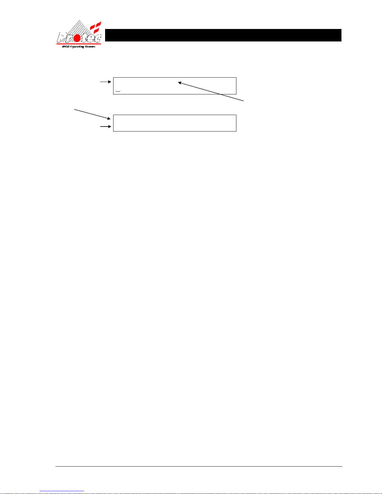
93-310-10 Issue 4 Rev 5 Page 80 of 88 Copyright Protec Fire Detection PLC
6400 OPERATING MANUAL
When the ‘View current fires’ is being displayed, press the ‘SELECT’ button, which will then display the following
options: -
• Viewing a fire event : To scroll through the fire events, press the ‘SELECT’ button while the cursor is
flashing on the ‘View next fire / alarm’ option. Once pressed, the ‘Event’ will increment
and the lower LCD will display the new event details. Pressing ‘Mute’ will cycle
through the options shown below :-
• Location text : To view the location text for fire events, the ‘View location text’ option should be
selected.
• Alarm text : To view the alarm text for fire events, the ‘View alarm text’ option should be selected.
• Show Details : To view the Fire details ( Node, Loop, Zone, etc.) for fire events, the ‘Show details’
option should be selected.
• 20 Fire Events : The repeat panels can each store a maximum of 20 fire events.
• Exit option : To return to the previous menu level, press the ‘MENU’ button.
N.B. Refer to Section 17.2 for instructions on how to select menu options.
XX Events : Event XX SYSTEM FIRE
VIEW NEXT FIRE/ALARM
Displays the event number.
1 = first event to occur.
Highest number = last event to occur.
Number of fire events
currently on the system.
Node XX Lp X Add XX Zone XX
20 Aug 2006, 10:17
Technical location
details.
Date and time of the
activation
Page 81

93-310-10 Issue 4 Rev 5 Page 81 of 88 Copyright Protec Fire Detection PLC
6400 OPERATING MANUAL
S
SIILL
E
E
N
N
C
CII
N
N
G
G
F
FII
R
R
E
E
E
E
V
V
E
E
N
N
T
T
S
S
19.1 SILENCING FIRE EVENTS
Note - This function is only available on the RDN (see section 14).
Pressing the ‘SILENCE’ button after any FIRE event will silence the system alarms. The buzzer will silence and the
following will be shown on the upper LCD :-
DO NOT at this stage attempt to ‘RESET’ the system until the cause of the fire has been established.
If an activation of another fire occurs once the sounders have been silenced, the buzzer will return to fast pip, the
sounders will reactivate and the ‘Alarms silenced’ indication will be removed.
FIRE X of X ALARMS SILENCED
Node xx Lp x Add xx Zone xx
Indicates that ALL
alarm outputs have
been silenced.
Text will be shown
for the Node / Loop
when available.
Page 82

93-310-10 Issue 4 Rev 5 Page 82 of 88 Copyright Protec Fire Detection PLC
6400 OPERATING MANUAL
R
R
E
E
S
S
E
E
T
T
T
TII
N
N
G
G
A
A
F
FII
R
R
E
E
E
E
V
V
E
E
N
N
T
T
20.1 RESETTING A FIRE EVENT
Note - This function is only available on the RDN (see section 14).
After ‘Silencing Alarms’ (section 19.1) and establishing the cause of the fire, the ‘RESET’ button can be pressed. All
current fire activations will be reset and the panel will display the system status as being ‘System Normal’ as shown
previously in section 15.1
Any fire indications will be extinguished.
Any plant equipment (control outputs) will be reset.
Page 83
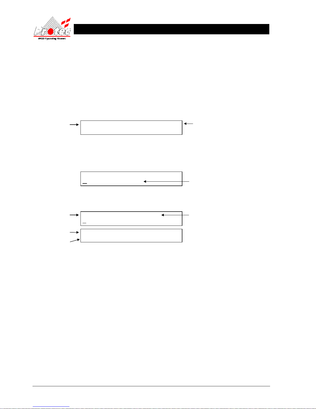
93-310-10 Issue 4 Rev 5 Page 83 of 88 Copyright Protec Fire Detection PLC
6400 OPERATING MANUAL
V
VII
E
E
W
W
C
C
U
U
R
R
R
R
E
E
N
N
T
T
F
F
A
A
U
ULL
T
T
S
S
21.1 VIEW CURRENT FAULTS
Note – Fault events can only be viewed if the repeat panel is configured to show faults.
In the event of a fault activation occurring the repeat panel’s audible buzzer will sound (1 second on / 1 second off). The
‘Fault‘ lamp will illuminate and the following will be displayed on the upper LCD: -
To view the fault events press the ‘MENU’ button and then using the ‘MUTE’ button scroll through the ‘Menu options’
until the upper LCD displays: -
When the ‘View current faults’ is shown, press the ‘SELECT’ button and the following options will be displayed:-
• Viewing events : To scroll through the fault events, press the ‘SELECT’ button while the cursor is flashing on
the ‘View next fault’. Once pressed the ‘Fault Event Number’ will increment and the lower
LCD will display the new event details. Pressing ‘Mute’ will cycle through the options
described below :-
• Location text : The location text for the fault events can be displayed (if available), by selecting the ‘View
location text’ option when viewing the correct fault event number.
• Show Details : The Fault details (Node, Loop, Zone etc) for the fault events can be displayed by selecting
the ‘Show details’ option when viewing the required fault event number.
• 30 Faults Events : The repeat panels can each store a maximum of 30 fault events.
• Exiting option : To return to the previous menu level, press the ‘MENU’ button.
N.B. Refer to Section 17.2 for instructions on how to select menu options.
xx Faults 20 May 2006, 10:17
PROTEC FIRE DETECTION PLC
MENU OPTIONS :-
VIEW CURRENT FAULTS
XX Faults : Fault Event Number XX
VIEW NEXT FAULT
Node XX Lp X Add XX Zone XX
20 Aug 06, 10:17:34 Fault description
Displays the fault event number.
1 = first event to occur.
Highest number = last event to occur.
Number of fault events
currently on the system.
Displays the menu
option for selection
Technical location details.
Time and date of the
activation
System Status
xx = Number
of faults
Current date & time
Page 84
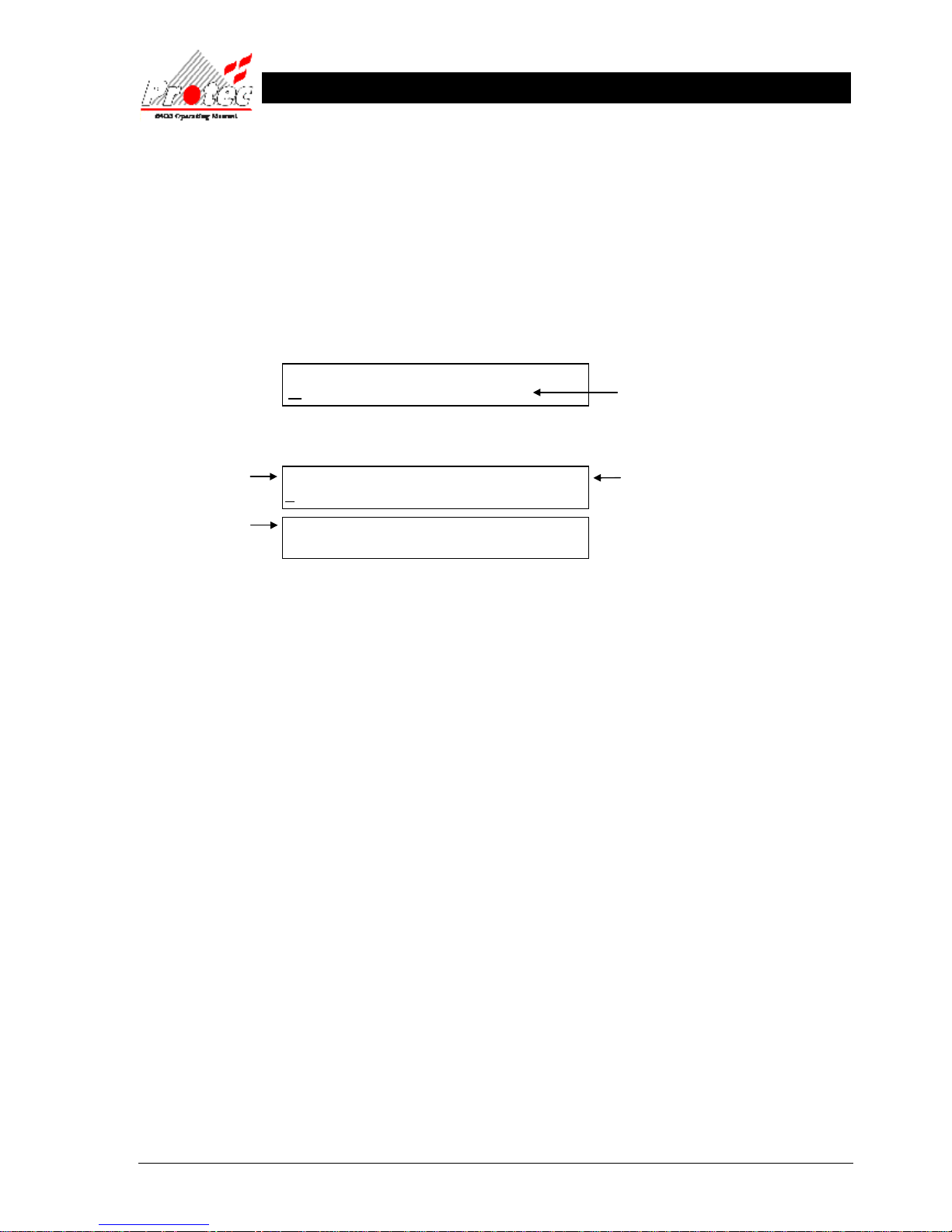
93-310-10 Issue 4 Rev 5 Page 84 of 88 Copyright Protec Fire Detection PLC
6400 OPERATING MANUAL
VVIIEEW
W CCUURRRREENNTT DDIISSAABBLLEE
M
MEENNTTSS
22.1 VIEW CURRENT DISABLEMENTS
Note – Disablements can only be viewed if the repeat panel is configured to show disablements.
In the event of a disablement occurring, the ‘Disablement‘ lamp will illuminate.
To view the disablements, press the ‘MENU’ button and then using the ‘MUTE’ button scroll through the ‘Menu
options’ until the upper LCD displays: -
When ‘View current disablements’ is shown, press the ‘SELECT’ button and the following will be displayed: -
• Viewing
Disablements : To scroll through the disablements, press the ‘SELECT’ button while the cursor is flashing
on ‘View next Disablement’. Once pressed the ‘Disablement Number’ will increment and the
lower LCD will display the new event details. Pressing the ‘Mute’ button will cycle through
the options described below :-
• Location text : The location text for the disablement events can be displayed (if available), by selecting the
‘View location text’ option when viewing the correct disablement event number.
• Show details : The disablement details can be displayed by selecting the ‘Show details’ option when
viewing the required disablement event number.
• 30 Disablements : The repeat panels can each store a maximum of 30 disablement events.
• Exiting option : To return to the previous menu level, press the ‘MENU’ button.
N.B. Refer to Section 17.2 for instructions on how to select menu options.
MENU OPTIONS :-
VIEW CURRENT DISABLEMENTS
XX Disablements : Disablement Number XX
VIEW NEXT DISABLEMENT
Disablement
description
Displays the disablement number.
1 = first event to occur.
Highest number = last event to occur.
Number of disablements
currently on the system.
Displays the menu
option for selection
Disablement details
Page 85

93-310-10 Issue 4 Rev 5 Page 85 of 88 Copyright Protec Fire Detection PLC
6400 OPERATING MANUAL
P
P
R
RII
N
N
T
TII
N
N
G
G
23.1 PRINTING - RDN Only
Note – Printing is only available if the repeat panel is configured to be used with a printer.
On the RDN there is the option of being able to print events. There are three printing options as follows: -
1 Print current fires
2 Print current faults
3 Print current disablements
N.B. The user can only print faults and disablements when the repeat panel has been configured to show faults and
disablements respectively. Obviously, the panel needs to have been configured to use a printer also.
To print one of the three options above, the user needs to enter the menus by pressing the ‘MENU’ button. The ‘MUTE’
button should then be pressed to cycle through the available options until the upper LCD shows the required option as
shown below: -
When the required option is shown, press the ‘SELECT’ button to commence printing.
Once printing has been started, printing will continue until all the events of the chosen type have been printed. Printing
can be cancelled at any time by pressing the ‘SELECT’ button (when outside of the menus).
N.B. Refer to Section 17.2 for instructions on how to select menu options.
MENU OPTIONS :-
PRINT CURRENT FIRES / ALARMS
Displays the menu
option for selection
Page 86
93-310-10 Issue 4 Rev 5 Page 86 of 88 Copyright Protec Fire Detection PLC
6400 OPERATING MANUAL
LLAAM
MPPTTEESSTT
24.1 LAMPTEST
To perform a lamptest, press the ‘MENU’ button and then using the ‘MUTE’ button scroll through the ‘Menu options’
until the upper LCD displays: -
When ‘Lamptest’ is shown, press the ‘SELECT’ button and the panel will briefly illuminate all LEDs and test the LCDs.
AABBO
ORRTT PPRRIINNTT
O
OUUTT
25.1 ABORT PRINTOUT
To abort a printout, press the ‘MENU’ button and then using the ‘MUTE’ button scroll through the ‘Menu options’ until
the upper LCD displays: -
When ‘Abort Printout’ is shown, press the ‘SELECT’ button and the panel will cancel the current printout.
MENU OPTIONS :-
LAMPTEST
Displays the menu
option for selection
MENU OPTIONS :-
ABORT PRINTOUT
Displays the menu
option for selection
Page 87
93-310-10 Issue 4 Rev 5 Page 87 of 88 Copyright Protec Fire Detection PLC
6400 OPERATING MANUAL
L
L
O
O
O
O
P
P
R
R
E
E
P
P
E
E
A
A
T
T
P
P
A
A
N
N
E
E
L
L
LOOP LCD PANEL
26.1 NORMAL DISPLAY
In normal operation the loop LCD Panel displays :-
• The ‘Power’ led is lit while there is power on the loop.
• The ‘Disablement’ led is lit when there are disablements on the 6400 system however the Loop LCD Panel does not
display them.
• The LCD backlights are not switched on when the system is in the normal state.
FIGURE 1
Fire
Power
Location Text LCD
Indications
System Status LCD
Disablement
Fault
6400
LCD Repeat Display
SYSTEM NORMAL - 8:59
PROTEC FIRE DETECTION
More Alarms
Scroll
Mute
Lamp
Page 88
93-310-10 Issue 4 Rev 5 Page 88 of 88 Copyright Protec Fire Detection PLC
6400 OPERATING MANUAL
26.2 FAULT DISPLAY
If there is a fault on the system then the loop LCD Panel displays it on the upper LCD. If it is a device related fault then
the location text is shown on the lower LCD eg :-
• The ‘Fault’ led is lit to indicate that there is a fault to view
• The Loop LCD Panel buzzer will mute if the fault event is accepted at the 6400 panel or it can be muted locally by
pressing the ‘MUTE’ button.
• If there is more than one fault to display then the faults are rotated automatically every three seconds.
26.3 FIRE DISPLAY
If there is a fire on the system then the loop LCD Panel displays it on the upper LCD. The device location text is shown
on the lower LCD eg :-
• The ‘Fire’ led is lit to indicate the fire alarm event
• The Loop LCD Panel buzzer will mute if the fire event is accepted at the 6400 panel or it can be muted locally by
pressing the ‘MUTE’ button.
• If there is more than one fire to display then the ‘More Alarms’ led is lit. The additional fires are viewed by pressing
the ‘Scroll’ button or rotated automatically every three seconds depending upon an internal switch. Fire events have
a higher priority than fault events therefore it is not possible to view fault events while fire events are present.
• Note that the device ‘alarm text’ is not displayed by the Loop LCD Panel.
26.4 LAMP TEST
Press ‘Lamp Test’ to test the leds and sound the internal buzzer.
DEVICE FAULT 14/10/06 09:02:13
BUILDING 4 ADDRESS 44
DEVICE LOCATION TEXT
IS DISPLAYED HERE
FIRE IN ZONE 5 14/10/06 09:06:27
BUILDING 4 ADDRESS 6
DEVICE LOCATION TEXT
IS DISPLAYED HERE
 Loading...