

Page 1
1
Page 2

SWIMMING POOL
HEAT PUMP UNIT
Installation & Instruction Manual
2
Applicable for:
P- Model
PC- Model
AC- Model
General information
Page 3
1. Please read this manual carefully before you install the product. Failure to do so may lead to
damage of the heat pump or injury to operators as well as cause financial loss.
2. Scientific and technological developments may lead to product improvements as well:
please check with us regularly to ensure that you are up to date with the latest product
developments.
3. If you need any further technical information, please contact your local distributor.
4. Attention:
4.1 Before installing the heat pump, please check whether the local power supply corresponds
with the requirement of the heat pump. For details, refer to the label on the unit or performance
data in this manual.
4.2 Please install the electrical protection devices according to the local regulations.
4.3 Connecting the heat pump to a ground wire is necessary in order to prevent electrical
shock caused by an unexpected short circuit inside the unit.
4.4 An electrical wiring diagram is provided in this manual.
4.5 For safety reasons, please do not change or repair the heat pump by yourself. If it is
necessary, please contact your local distributor for help.
4.6 Do not put any objects into the heat pump when running as these may touch the fan and
damage it or lead to accidents (particularly for children).
4.7 Do not use the heat pump without the grid or plate work since it may lead to accidents or
abnormal operation of the unit.
4.8 If the unit is soaked in water, please contact your local distributor immediately. The unit
can only be restarted after a thorough inspection by professional technicians.
3
4.9 Unqualified technicians are not allowed to adjust any switches, valves or controllers in the
unit.
Page 4

g
g
g
Contents
1. Performance data and installation
1.1 Performance and features..................................................................................................................... 5
1.2 Working principles ................................................................................................................................ 5
1.3 Where to install the heat pump.............................................................................................................. 6
1.4 Distance from the pool.......................................................................................................................... 7
1.5 Installation of the check-valve............................................................................................................... 8
1.6 Pool system set up ............................................................................................................................... 9
1.7 Connectin
the by-pass ........................................................................................................................9
1.8 Electrical connection............................................................................................................................. 10
1.9 First time start-up ................................................................................................................................. 11
1.10 Condensation ..................................................................................................................................... 11
2. Controlling the heat pump (LCD)
Only for LCD Display - not applicable.
3. Controlling the heat pump (LED)
3.1 Controller diagram ............................................................................................................................... 12
3.2 How to start heat pump ........................................................................................................................ 12
3.3 How to change mode ........................................................................................................................... 13
3.4 How to set desired water temperature ................................................................................................ 13
3.5 How to change parameter setting - ONLY FOR DEALERS................................................................. 13
3.6 How to check parameter setting & measured values of current status ................................................ 14
3.7 How to set the clock ............................................................................................................................. 15
3.8 How to set timer start and timer stop .................................................................................................... 16
3.9 How to cancel timer start and timer stop .............................................................................................. 16
3.10 Keypad lock and unlock ..................................................................................................................... 16
4.Protection systems
4.1 Water flow switch ................................................................................................................................. 17
4.2 Refri
erant gas high and low pressure protection ................................................................................17
4.3 Overheating protection on the compressor .......................................................................................... 17
4.4 Automatic defrost control ...................................................................................................................... 17
4.5 Temperature difference between in-flowing and out-flowing water ...................................................... 17
4.6 Low temperature cut-off ....................................................................................................................... 17
4.7 Anti-frost protection during winter ......................................................................................................... 17
4.8 First anti-frost protection ....................................................................................................................... 17
4.9 Second anti-frost protection ................................................................................................................. 18
5.Recommendations
5.1 Swimming pool water chemistry ........................................................................................................... 18
5.2 Heat pump winterizing .......................................................................................................................... 18
5.3 Restarting the pump after winter .......................................................................................................... 19
5.4 Check-up .............................................................................................................................................. 19
6.Maintenance and inspection
6.1 Maintenance ......................................................................................................................................... 27
6.2 Troubleshooting guide .......................................................................................................................... 27
6.3 Overview of failure code on display (LCD CONTROLLER) - only for LCD - not applicable................. 30
6.4 Overview of failure code on display (LED CONTROLLER) ................................................................. 30
6.5 Failure code table for Chiller-300 three phase ..................................................................................... 31
6.6 Failure code table for Protect 300 ........................................................................................................ 33
6.7 Failure code table for general PCB (single-system) ............................................................................ 34
6.8 Failure code table for
eneral PCB (dual-system)- only for dual-system- not applicable...................... 35
4
7.Name plate & wiring diagram
7.1Name plate - not applicable.................................................................................................................... 35
7.2 Wiring diagram - not applicable............................................................................................................. 35
Page 5
1. Performance and Installation
1.1. Performance and Features
High Efficiency
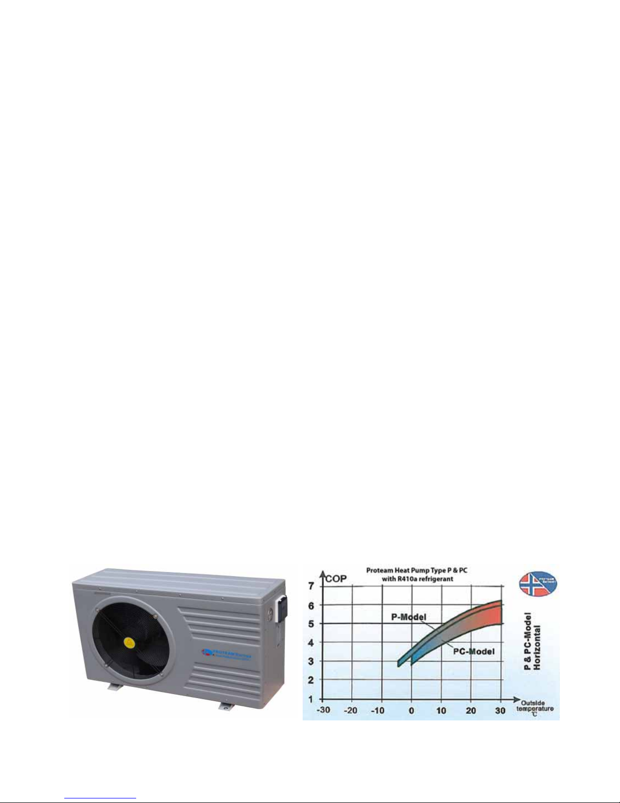
With a COP value up to 5.0, our heat pumps are very efficient when transferring heat from the
air to the swimming pool water. You can save as much as 80% of cost compared to an
electrical heater.
Long lifespan
The heat exchanger is made of PVC with titanium tube, which enables it to withstand
prolonged exposure to swimming pool water.
Easy control and operation
The unit is very easy to operate: simply switch it on and set the desired pool water
temperature. The system is equipped with a micro-computer controller, allowing all operating
parameters to be set. Operation status can be displayed on the controller with LED display.
5
1.2 Working Principles
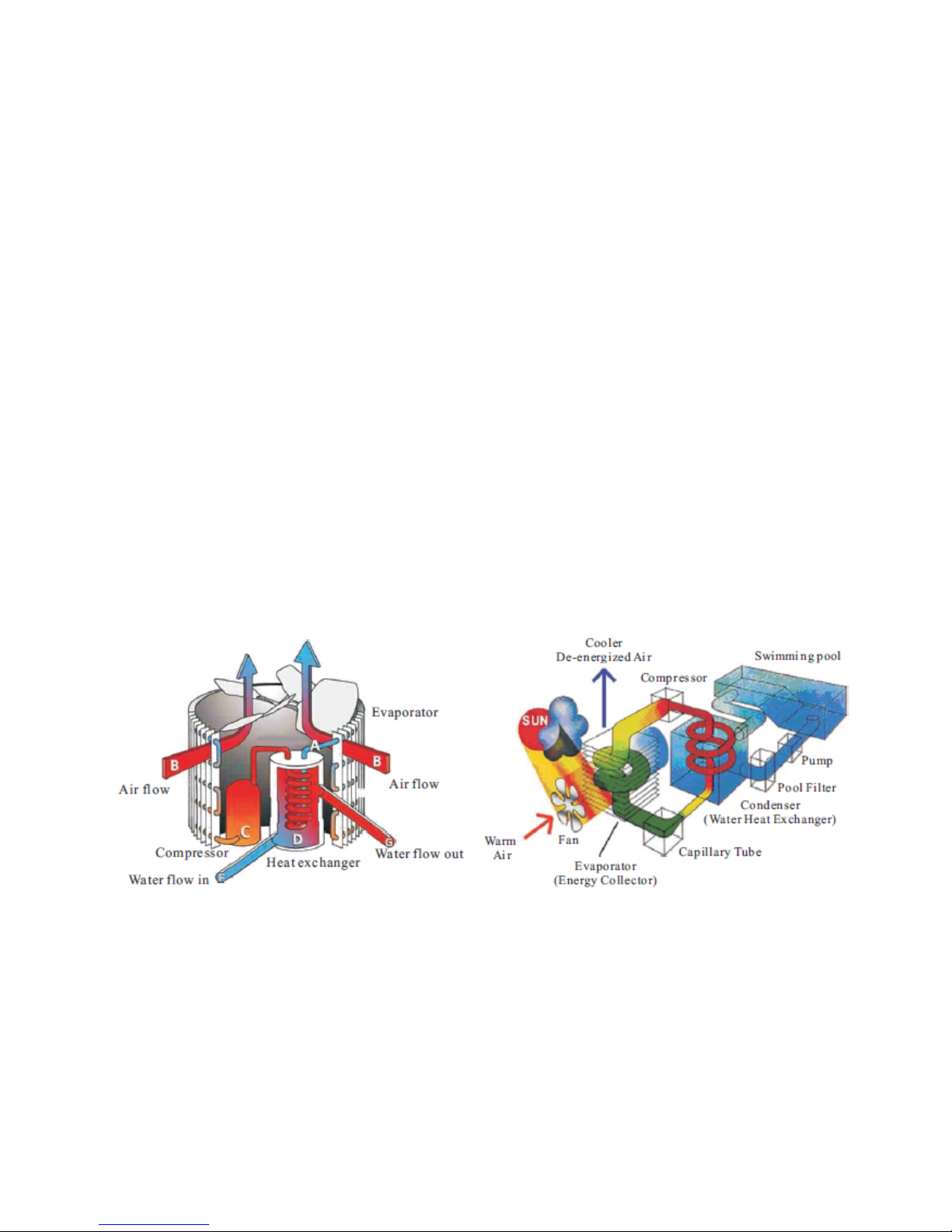
Heat pumps use heat from the sun by collecting and absorbing energy from the outside air.
This energy is then compressed and transferred to the pool water. Your existing water pump
circulates the water through the heat pump, which is normally installed next to the pool
filtration system, and the water warms up. The heat pump timer can be set so that the pump
operates at the times you want: for example, during daylight hours from 9am to 5pm.
The unit contains a fan that draws in outside air and directs it over the surface of the
EVAPORATOR (energy collector). The liquid refrigerant inside the EVAPORATOR coil
absorbs the heat from the outside air and becomes a gas.
The warm gas inside the coil passes through the COMPRESSOR, which concentrates
and increases the heat to form a very hot gas, which then passes through the
CONDENSER (water heat exchanger). It is here that the heat exchange occurs as the
Page 6
heat from the hot gas is transferred to the cool swimming pool water circulating through
the heat exchanger.
The pool water becomes warmer and the hot gas returns to its liquid form as it flows
through the CONDENSER coil. The gas then passes through the CAPILLARY TUBE
and the whole process begins again.
Developments in heat pump technology mean that today heat pumps can efficiently
collect heat from the outside air even when the temperature is as low as 7-10°C. This
means that for tropical and subtropical climates the pool can be maintained between
26°C and 32°C.
1.3 Where to install the heat pump
The unit will perform well in any location as long as the following are available:
Fresh air
Electricity
Pool filtration piping
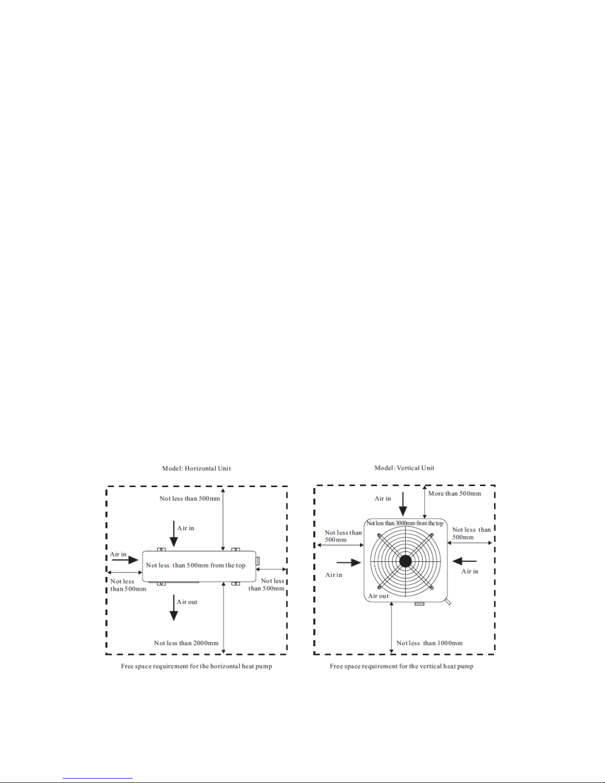
The unit can be installed almost anywhere outside provided the minimum distance
requirements with respect to other objects are met (see diagram below). For indoor pools,
please seek advice from your installer. If the unit is placed in a windy area, there are no
problems with the pilot light as is often the case with gas heaters.
6
Warning: Do not place the unit in an enclosed area with a limited air volume where the air
discharged by the unit will be re-circulated or near shrubs that could block the air inlet.
Installation in such locations will deny the unit a continuous supply of fresh air, which will
reduce its efficiency and may prevent adequate heat yield.
See diagram below for minimum distance requirements:
Warning:
- Do not place your hand or any other objects into the air outlet and fan. It could damage
the heat pump and cause injuries;
Page 7

- In case of any abnormality with the heat pump, cut off the power immediately and
contact a professional technician;
- It is strongly advised to place a protective guard around the unit to keep children away
from the heat pump.
1.4 Distance from the pool
Normally, the heat pump is installed within a 7.5m radius of the pool. The greater the distance
from the pool, the greater will be the heat loss from the piping. Since the piping is buried for
the most part, heat loss is minimal for distances up to 15m between pump and pool (total to
and from pump: 15m x 2 = 30m), unless the soil is wet or the water level is high. Heat loss per
30 metres could roughly be estimated at 0.6kw-hour (2000BTU) for every 5°C temperature
difference between the pool water and the soil surrounding the pipe, which translates into an
increase in operating time of 3-5%.
7
Page 8
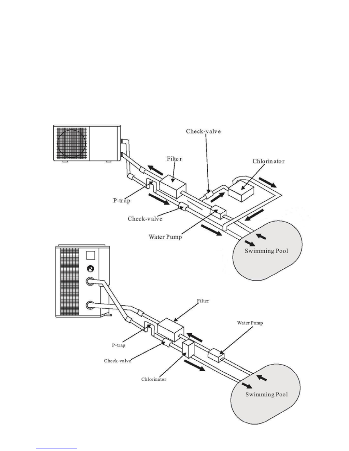
1.5 Installation of check-valve
Warning: When using automatic chlorine and pH dosing systems, it is of utmost importance to
protect the heat pump from high concentrations of chemicals as they could corrode the heat
exchanger. It is therefore recommended that these systems should add the chemicals into the
pipes located DOWNSTREAM (after) of the heat pump, and it is also recommended that a
check-valve be installed in order to prevent backflow when there is no water in circulation.
Damage to the heat pump caused by disregarding any of these recommendations will
invalidate the warranty.
8
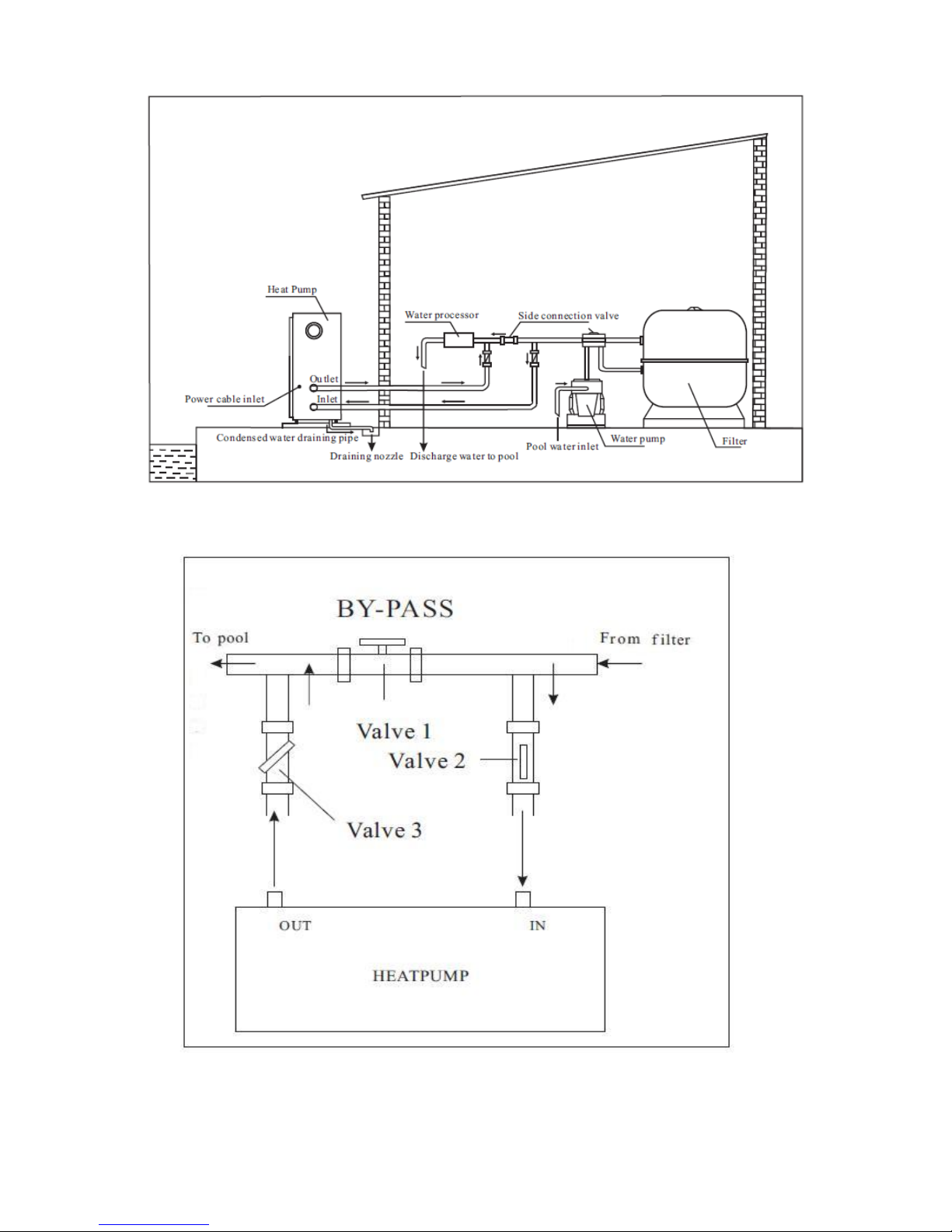
1.6 Pool system set up
Page 9
9
1.7 Connecting the by-pass
Page 10
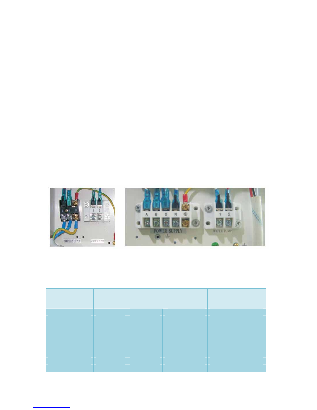
1.8 Electrical Connection
Important – although the heat pump is electrically isolated from the rest of the unit, this only
prevents the passage of water to or from the pool water. It is still necessary to ground the unit
to protect yourself from short circuits inside the unit. Make sure there is an adequate ground
connection.
Check if the voltage of the electrical mains corresponds with the operating voltage of the heat
pump prior to connecting the unit.
It is recommended to use a separate fuse (slow-type D-curve) as well as adequate wiring (see
table below).
For horizontal models: remove the panel on the right of the fan opening.
For vertical models: remove the curved panel on the front side.
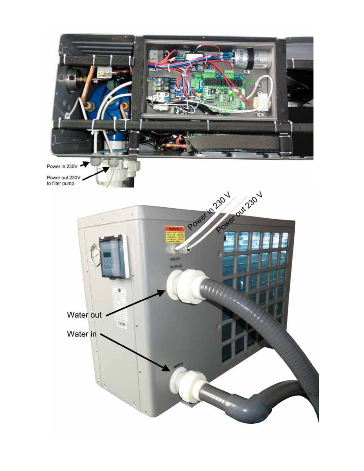
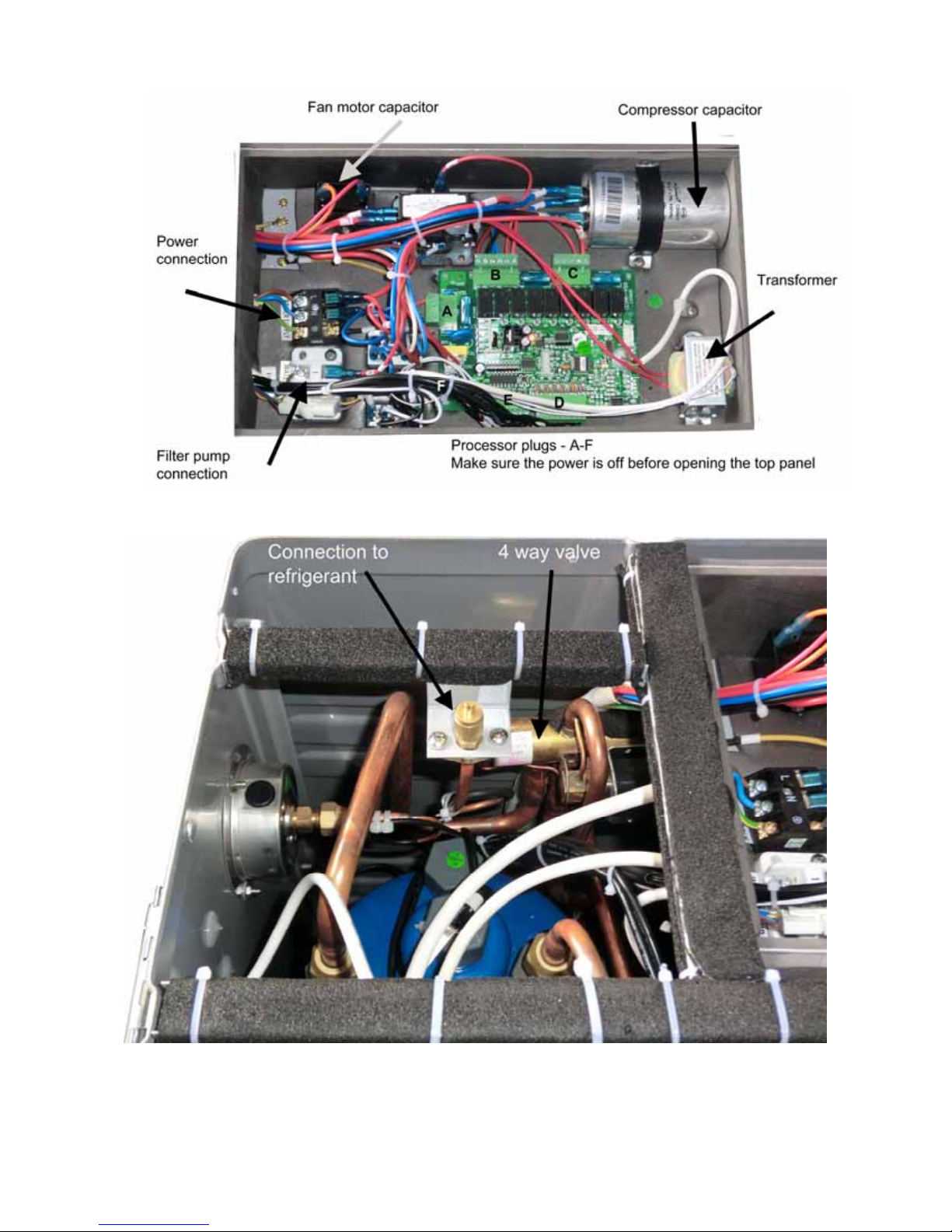
Connect the terminal wires with the terminal block labelled ‘Power Supply’. Next to this
connection there is a second terminal block labelled ‘Water Pump’, to which the filter pump
(max 5A / 240V) can be connected. This connection makes it possible to control the filter
pump operation with the heat pump. See the Parameter Setting Table below (Parameter 9) for
other possibilities.
10
Remarks: for models with 3 phases, switching 2 phases may cause an inversion of the
rotational direction of the electrical motors, which could damage the unit. Therefore, a
protection device has been built in, which will interrupt the circuit if the connection has not
been carried out correctly.
Model Voltage
(volt)
Fuse
T3/ slow blow
(A)
Nominal
current
(A)
Cable diameter (mm2)
(for max. Length of 20
meters)
P5/ PC6 220 - 240 10 3.9 2x2.5 mm2+ Ground
P6/ PC8/ AC6P 220 - 240 10 4.55 2x2.5 mm2+ Ground
P8/ PC10/ AC10P 220 - 240 16/ 13 6.64 2x2.5 mm2+ Ground
P10/ PC13/ AC13P 220 - 240 16/ 13 7.87 2x2.5 mm2+ Ground
P13/ PC15/ AC15P 220 - 240 16/ 13 9.78 2x2.5 mm2+ Ground
P15/ PC17/ AC17P 220 - 240 20/ 16 11.03 2x2.5 mm2+ Ground
P17/ PC20 220 - 240 25/ 20 14.88 4x2.5 mm2+ Ground
P21/PC25/AC25P 380- 400 16 6.36 3x2.5 mm2+ Ground
P25/PC30 380- 400 16 7.42 3x2.5 mm2+ Ground
1.9 First-time start-up
Page 11

Note: in order for the unit to heat the pool (or spa), the filter pump must be running so
that the water can circulate through the heat pump. Without this circulation, the heat
pump will not start.
When all connections have been made and checked, the following steps should be followed:
1. Turn on the filter pump. Check for leaks and verify that there is a flow to and from the
pool.
2. Turn on the electrical power supply to the unit, then press the ON/OFF key on the
electronic control panel. The unit should start when the time delay period has lapsed.
3. When the unit has been running for a couple of minutes, check if the air leaving the unit
is cooler.
4. Check the performance of the flow switch as follows: with the unit running turn the filter
pump off. The unit should also switch off automatically. If not, the flow switch must be
readjusted.
5. The unit and the filter pump should run 24 hours a day until the desired pool water
temperature has been reached. Once the set temperature is reached, the unit will
switch itself off. As long as the filter pump is running, the unit will restart automatically
when the temperature of the pool water drops more than 1°C below the set
temperature.
11
Depending on the starting temperature of the pool water and the air temperature, it can take
several days for the water to reach the desired temperature. Covering the pool with a pool
cover can reduce this period significantly.
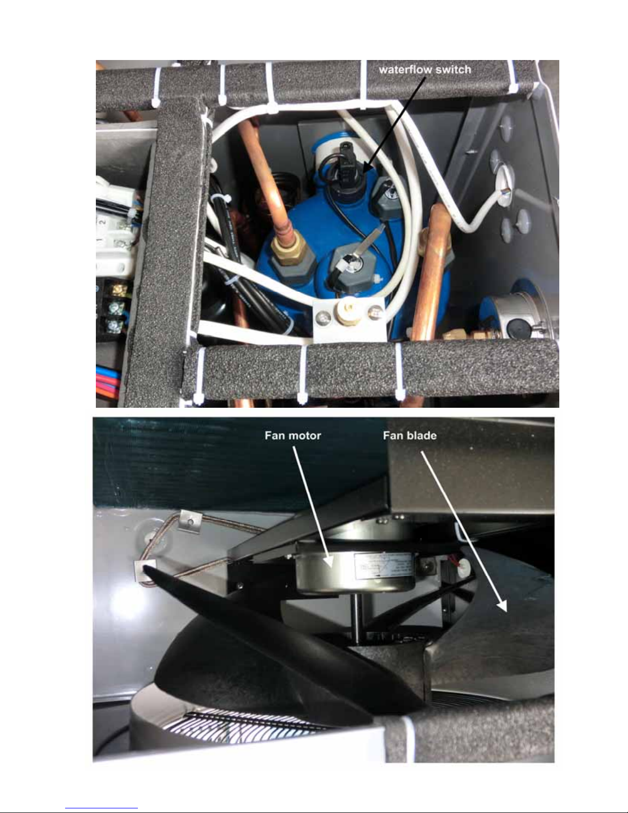
Water flow switch: the unit is equipped with a flow switch that switches on when enough
water flows through the unit and switches off when the water flow becomes too low (e.g. when
the filter pump is switched off).
Time delay: the unit is equipped with a built-in 3-minute start delay to protect electrical
components and contacts. After this time delay, the unit will automatically restart. Even a brief
interruption in the power supply will activate the start delay and prevent the unit form starting
immediately. Additional interruptions of the power supply during the delay period will have no
effect on the 3-minute countdown.
1.10 Condensation
When the swimming pool water is being heated by the heat pump, the incoming air is cooled
down considerably, which can cause condensation on the fins of the evaporator.
Condensation volumes can reach several litres per hour under high atmospheric humidity.
This can sometimes be incorrectly interpreted as water leakage.
2. Controlling the heat pump (LCD)
Not applicable.
3. Controlling the heat pump
Preparation before start-up
(LED)
Page 12
A) Inspection of the heat pump
- Check whether the outer appearance of the unit or piping system has been
damaged during transportation.
- Check that the ventilator fan does not touch any part of the unit.
B) Verifying the electrical connections
- Check that the power supply complies with the specifications in this manual or
on the label placed on the unit.
- Check whether the power cabling is connected correctly and firmly according to
the wiring diagram. Adequate grounding is required to protect against electrical
shock.
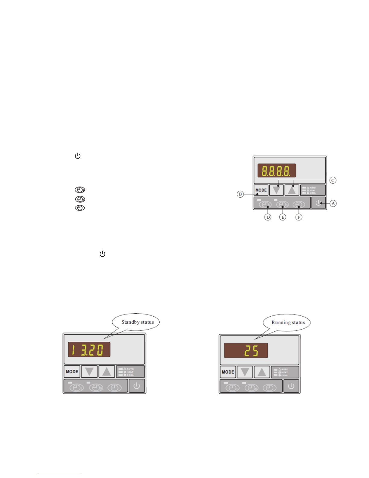
3.1 Controller diagram
A. : Switch heat pump on or off
B. MODE: Select auto, heating or cooling mode.
Corresponding indicator light will go on when selected
C. ▲ or ▼: Press to change digits.
D.
E.
F.
: ‘Timer start’ setting button
: ‘Timer stop’ setting button
: Time setting button
12
3.2 How to start heat pump
When connected with power, the controller will display the time. This means that the unit is in
standby. Press
to start the heat pump. The controller display will now show the inlet water
temperature.
Please note : If the buttons are touched many times, the processor will stop working
and you will be not able to change the mode. In this case turn off and then on the power
to the heat pump.
3.3 How to change mode
Press MODE to select auto, heating or cooling mode: the indicator light on the right side of the
controller will indicate the mode selected.
Page 13
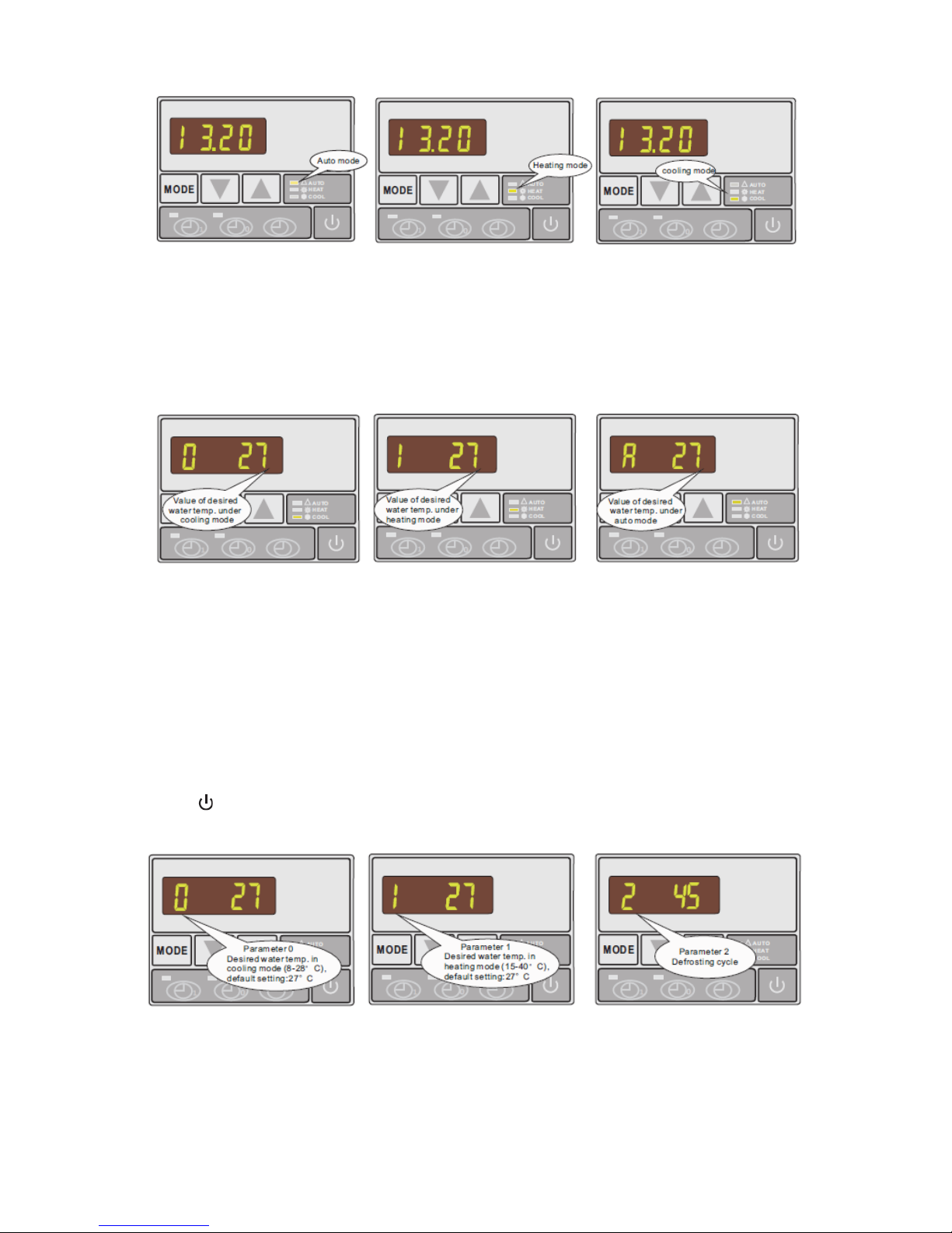
3.4 How to set the desired water temperature
1. First select the desired mode: auto, heating or cooling
2. Regardless of whether the heat pump is running or on standby, press ▲ or ▼. The
display will show the currently set water temperature of the selected mode with a
flashing number: change the water temperature by moving ▲ or ▼ as required
13
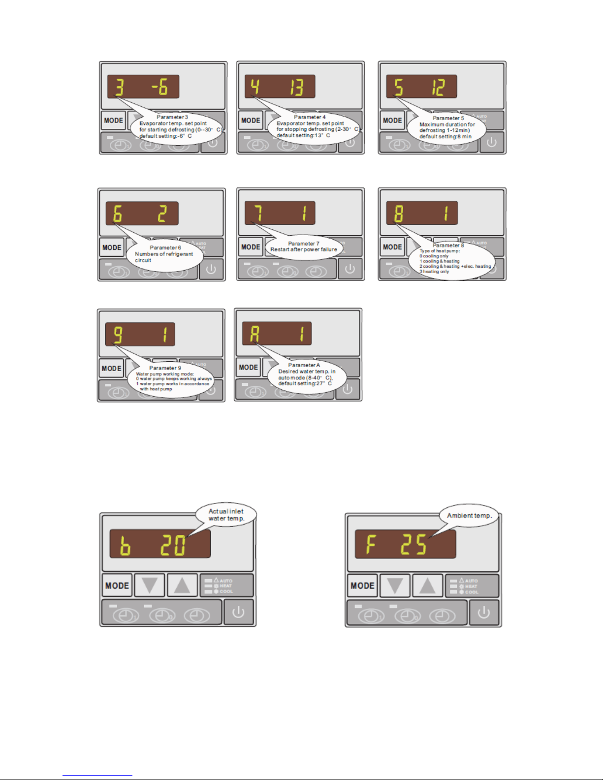
3.5 How to change parameter setting - ONLY FOR DEALERS
1. In standby status, press and hold MODE button for 5s, then use ▲ or ▼ to find
parameters 0-A and measured values of current status B or F, both parameter and
value will be blinking.
2. Press and hold ▲ and ▼ at the same time for 5 seconds continuously to activate
parameter setting
3. Change value on setting until a BEEP is heard while display continues to indicate
parameters by means of flashing values
4. Wait for 5 seconds to store the data automatically and return to standby status. Press
button to start the heat pump working.
Check if the heat pump is in required mode- auto, cooling, heating.
Page 14
14
3.6 How to check parameter settings and measured values of current status
In standby or running status press ▲ or ▼ to find parameter 0-A and measured values of
current status.
Page 15
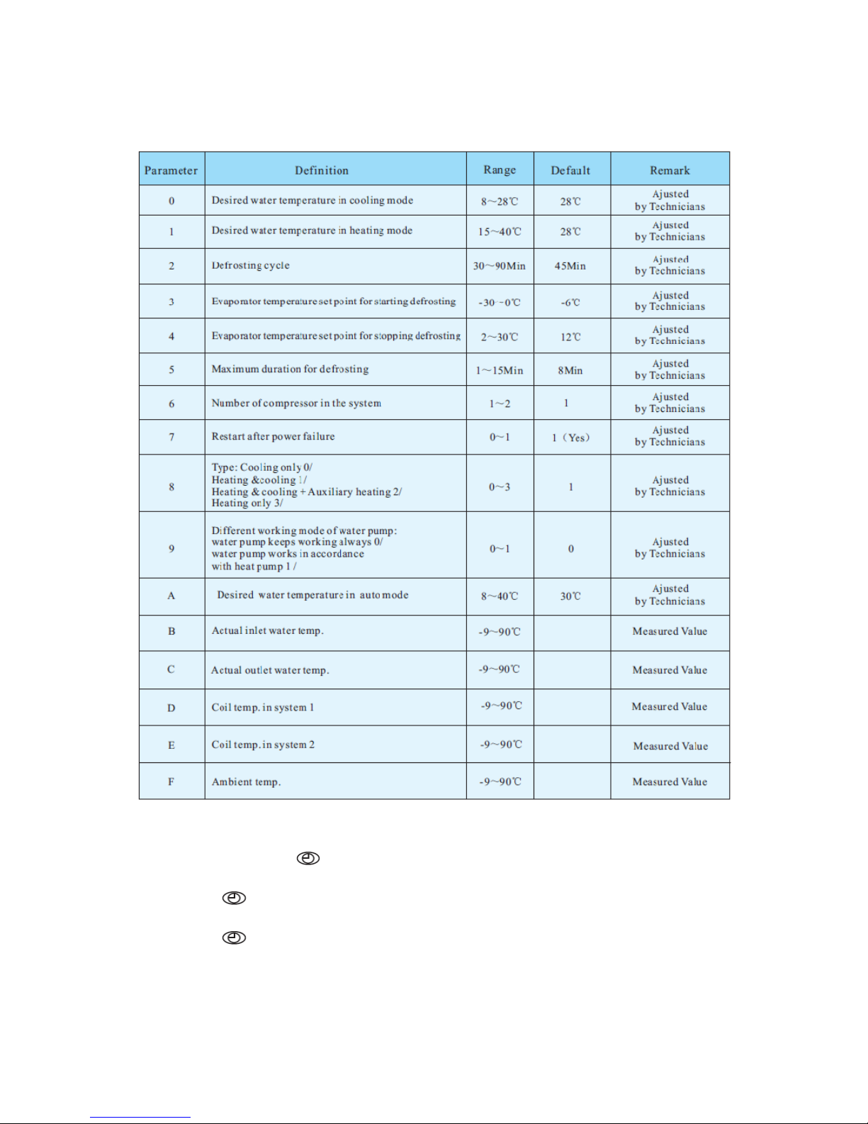
Parameter table overview
15
3.7 How to set the clock
1. In standby, press
pressing ▲ or ▼
2. Press
again: minute digits will flash to indicate that they can be modified by
pressing ▲ or ▼
3. Press
again for final confirmation of time setting
Once time has been set, LED display will show time when heat pump is on standby.
: hour digits will flash to indicate that they can be modified by
Page 16
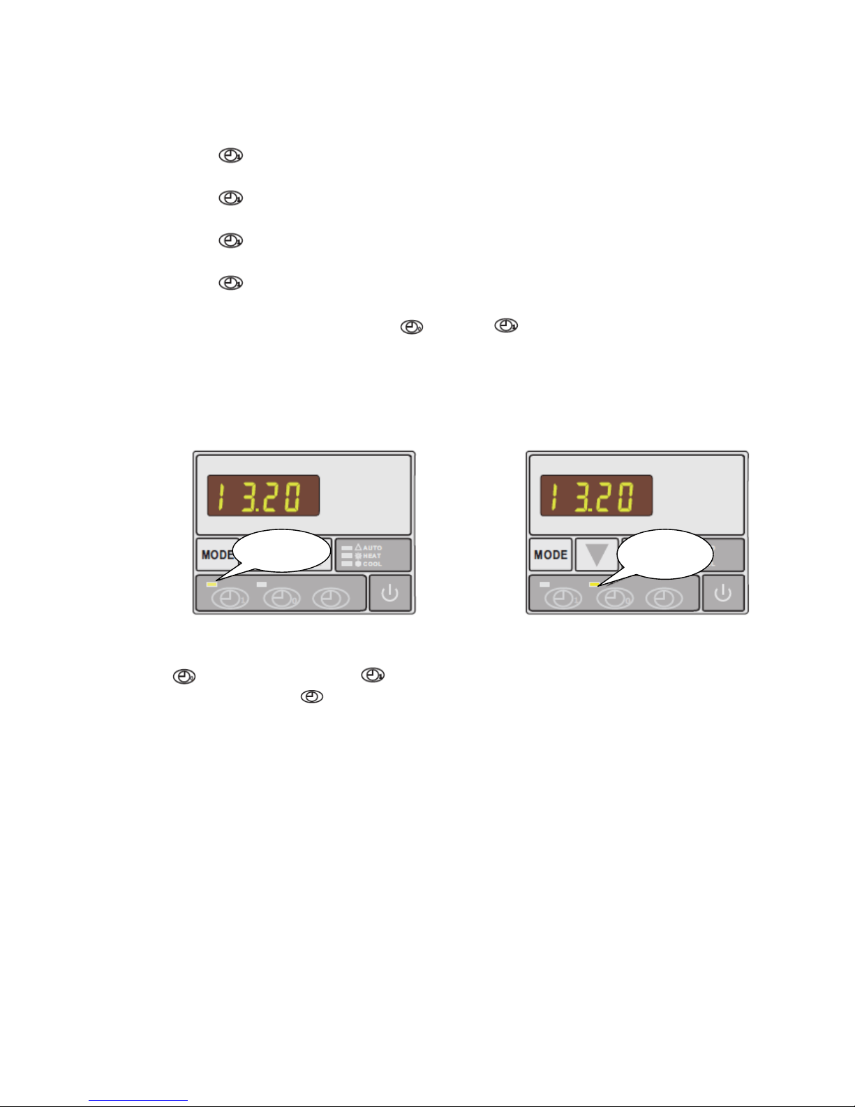
3.8 How to set timer start and timer stop
16
a) Press
to activate ‘timer start’ setting: hour and minute digits will be flashing
together.
b) Press
again to modify the hour setting: the hour digits will flash meaning they are
ready to be modified by pressing ▲ or ▼.
c) Press
again to modify the minute setting: the minute digits will flash meaning they
are ready to be modified by pressing ▲ or ▼.
d) Press
to confirm setting - display will return to standby status. ‘Timer start’ green
indicator light will light up to show the starting time has been set.
e) Repeat the same procedure using
instead of to set ‘timer stop’. ‘Timer stop’
red indicator light will light up to show the stopping time has been set.
Note: ‘timer start’ and ‘timer stop’ can be set together or separately (i.e. it is possible to set
‘timer start’ only and then stop the unit manually or set ‘timer stop’ only and start the unit
manually)
Timer start
indicator
Timer stop
indicator
3.9 How to cancel ‘timer start’ and ‘timer stop
Press
light will be flashing. Press
to activate ‘timer start’ or to activate ‘timer stop’: the corresponding indicator
to cancel ‘timer start’ or ‘timer stop’.
3.10 Locking and unlocking the keypad
Except during parameter setting, press and hold ▲ or ▼ at the same time for 3 seconds: you
will hear a BEEP and the keypad will be locked. To unlock, press and hold both buttons
simultaneously again for 3 seconds.
Page 17

4. Protection Systems
4.1 Water flow switch
The heat pump is equipped with a flow switch to ensure that it does not run when the filter
pump is not working (and the water is not circulating).
This system prevents the heat pump from heating only the water present in the heat pump
itself. The protection also stops the heat pump if water circulation is cut off or stopped.
4.2 Refrigerant gas high and low-pressure protection
The high-pressure protection ensures that the heat pump is not damaged in case of overpressurisation of the gas. The low-pressure protection emits a signal when refrigerant is
escaping from the conduits and the unit cannot be kept running.
4.3 Overheating protection on the compressor
This protection protects the compressor from overheating.
4.4 Automatic defrost control
17
When the air is very humid and cold, ice may form on the evaporator. In such cases, a thin
layer of ice appears that will grow increasingly bigger as long as the heat pump is running.
When the temperature of the evaporator becomes too low, the automatic defrost control will be
activated: this will reverse the heat pump cycle so that hot refrigerant gas is sent through the
evaporator for a brief period of time to defrost it.
4.5 Temperature difference between in-flowing and out-flowing water
During normal operation of the heat pump, the temperature difference between the water
flowing into and out of the unit will be approximately 1 to 2°C. In the event that the pressure
switch does not work and that the water stops circulating, the temperature probe monitoring
the out-flowing water will always detect a rise in temperature. As soon as the temperature
difference between in-flowing and out-flowing water exceeds 13°C, the heat pump will be
automatically turned off.
4.6 Low temperature cut-off
If, during cooling, the temperature of the out-flowing water reaches or drops below 5°C, the
heat pump will turn itself off until the water temperature reaches or exceeds 7°C.
4.7 Anti-frost protection during winter
This protection can only be activated if the heat pump is in STANDBY.
4.8 First anti-frost protection
If the filter pump is controlled by the heat pump (regardless of the value set for parameter 9),
when the water temperature is between 2 and 4°C, and the air temperature is lower than 0°C,
the filter pump will be automatically turned on to prevent the water in the pipes from freezing.
This protection is deactivated when the temperature rises again.
4.9 Second anti-frost protection
Page 18
If the water temperature drops further, i.e. below 2°C (during long periods of frost), the heat
pump will also start running to heat the water until the temperature reaches approximately 3°C.
Once this temperature is reached, the heat pump will stop but the anti-frost protection will
remain active until conditions change.
5. Recommendations
5.1 Swimming pool water chemistry
Special attention should be paid to the chemical balance of the pool water. The pool water
values should always stay within the following limits:
Min. Max.
pH
Free Chlorine (mg/l)
TAC (mg/l)
Salt (g/l)
7,0 7,4
-1,2
50 120
- 3
18
Important: failure to comply with these limits will invalidate the warranty
Note: exceeding one or several limits can damage the heat pump beyond repair. Always
install water-treatment equipment (e.g. chemical dosing systems) after the water outlet
of the heat pump, especially if the chemicals are automatically added to the water (e.g.
automatic chemical dosing systems).
A check valve should also be installed between the outlet of the heat pump and the
water-treatment equipment to prevent products from flowing back into the heat pump if
the filter pump stops.
5.2 Heat pump winterizing
Important: failure to take necessary precautions for winterising can damage the heat
pump, which will invalidate the warranty.
The heat pump, filter pump, filter and conduits must be protected in areas where the
temperature can drop below freezing point. Evacuate all water from the heat pumps as follows:
1. Interrupt the electrical power supply to the heat pump
2. Close the water supply to the heat pump: completely close valves 2 and 3 of the bypass
3. Disconnect water inlet and outlet coupling fittings of the heat pump and let the water
drain out of the unit
4. Loosely reattach water inlet and outlet coupling fittings of the heat pump in order to
prevent dirt from getting into the conduits.
Note: these precautions should be taken if you choose to use the built-in anti-frost
protection.
5.3 Restarting the pump after winter
If you emptied the heat pump for winterising, follow the steps below to restart it in spring:
Page 19

1. First check that there is no dirt in the conduits and that there are no structural problems
2. Check that the water inlet and outlet coupling fittings are adequately fastened to the
heat pump
3. Start the filter pump to start the water flow to the heat pump. Set the by-pass again.
4. Reconnect the electrical power supply to the heat pump and turn it ON.
5.4 Check-up
Our heat pumps have been built and developed to last if they have been installed correctly and
can operate in normal conditions. Regular check-ups are important if you want your heat pump
to function efficiently for many years. Below are some recommendations to ensure optimal
working conditions for your heat pump.
1. Make sure that the service panel is easily accessible.
2. Keep the area surrounding the heat pump free of organic waste.
3. Prune any vegetation around the heat pump so that there is sufficient free space
around the pump.
4. Remove any water sprinklers that are near the heat pump as they could cause damage
to it.
5. Prevent rain from running directly onto the heat pump from a roof. Install proper
drainage.
6. Do not use the heat pump if it has been flooded. Immediately contact a qualified
technician to inspect the heat pump and repair it should it be necessary to do so.
19
Condensation can occur when the heat pump is running. This condensation water can flow
away through an opening in the base pan of the unit. The amount of condensation water will
increase when atmospheric humidity is high. Remove any dirt that could impede the discharge
of the condensation. 10 to 20 litres of condensation water can be produced while the unit is
running. If more condensation is produced, stop the heat pump and wait for one hour before
checking for leaks in the conduits.
Note: a quick way to verify that the water running through the condensation is indeed
condensation is to shut off the unit and keep the pool pump running. If the water stops
running out of the condensation drain, it is condensation. AN EVEN QUICKER WAY is
to TEST THE DRAIN WATER FOR CHLORINE. If no chlorine is detected, the drain water
is a result of condensation.
Also make sure that the air inlet and exhaust passages are free, and prevent exhaust air from
immediately re-entering the unit through the inlet.
Dubai,
Page 20
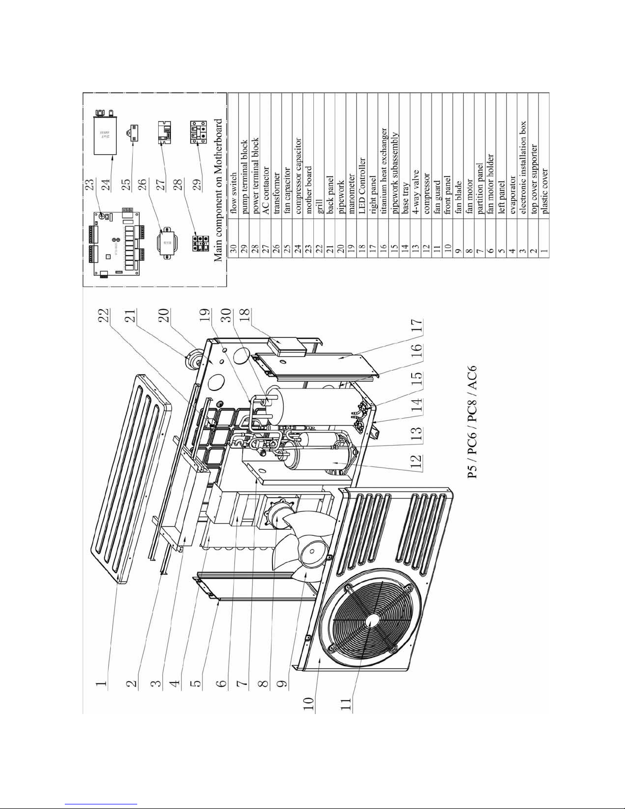
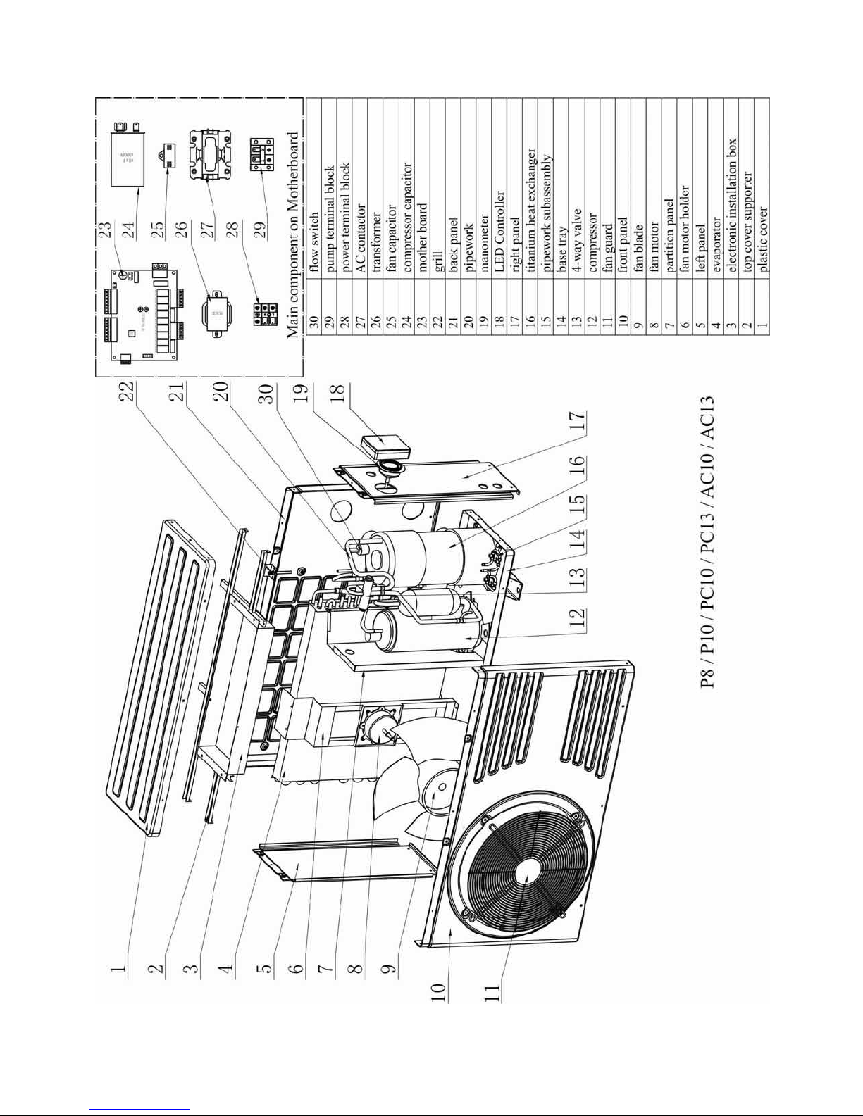
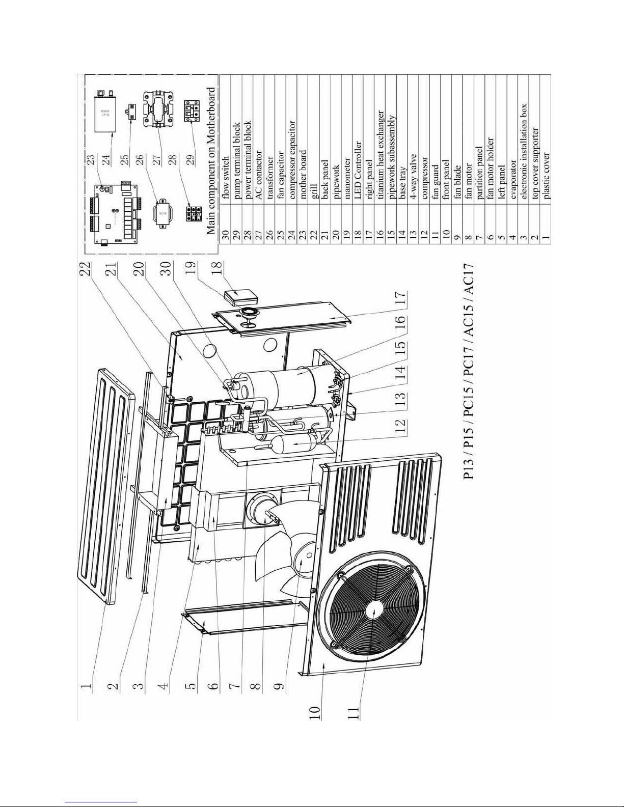
6. Maintenance and Inspection
20
Page 21
21
Page 22
22
Page 23
23
Page 24
24
Page 25
25
Page 26
26
6.1 Maintenance
Page 27

Check the water inlet and drainage often. The water and air inflow into the system
should be sufficient so that its performance and reliability are not compromised. Clean
the pool filter regularly to avoid damage to the unit caused by clogging of the filter.
Sufficient space should be left around the unit and the area should be well ventilated.
Clean the sides of the heat pump regularly to maintain optimal heat exchange
conditions and to save energy.
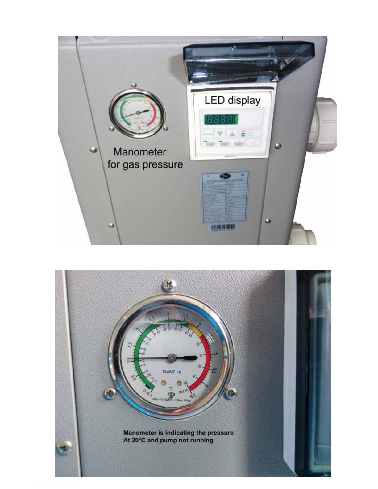
Check that all the processes in the unit are operational and pay special attention to the
operating pressure of the refrigerant system.
Check the power supply and cable connections regularly. Should the unit begin to
function abnormally or should you notice a smell coming from an electrical component,
arrange for timely repair or replacement.
Empty the water from the unit if you will not use it for a long time. You should check all
parts of the unit thoroughly and completely fill the system with water before turning it on
again after such a prolonged period without use.
6.2 Troubleshooting guide
Incorrect installation may result in an electrical charge that could lead to death or serious injury
of users, installers or others by electrical shock, and it may also cause damage to property.
DO NOT attempt to modify the internal configuration of the heat pump.
27
1. Keep your hands and hair clear of the fan blades to avoid injury.
2. If you are not familiar with your pool filtration system and heat pump:
a. Do not attempt to carry out any adjustment or service without consulting your
dealer, pool professional or air conditioning contractor.
b. Read the entire installation manual before attempting to use, service or make
adjustments to the unit.
c. Start the heat pump at least 24 hours after its installation in order to prevent
damage to the compressor.
Note: Switch off the power before carrying out any maintenance or repairs
IMPORTANT REMARK
: if a malfunction cannot be resolved immediately, in order to analyse
the problem we will need to know the message (error code) that is displayed on the controller
as well as the values for the settings (parameters 00-10 for LCD display and parameters 0-A
for LED display). We also need to know the status of the heat pump (ambient temperature,
water inlet / outlet temperature and system coil temperature) just before the failure or, if this is
not possible, just after it.
Please keep this information at hand when calling customer service.
On the following pages you will find an overview of the different types of failure problems that
can occur together with instructions on how to solve them.
Problem:
Observat
ion:
the heat pump doesn't work
the screen does not light up and the fan/compressor doesn't make a sou nd
Page 28
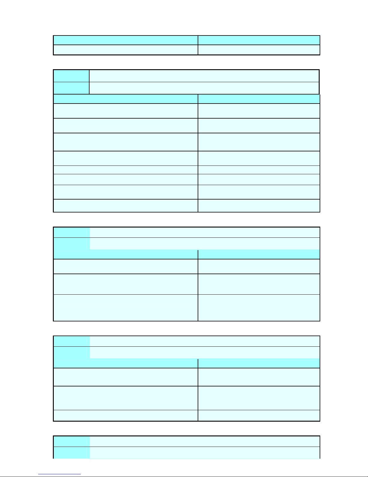
Possible cause Solution
No electrical power supply
Check power supply (wiring, fuses,…………)
28
Problem
:
Observat
ion:
the heat pump works normally but there is no or insufficient heating
The screen displays the temperature but no error codes
Possible cause Solution
1. Insufficient capacity of the heat pump in proportion to the
size of the swimming pool
2. The compressor works but the fan doesn 't
3. The fan works but the compressor doesn't
4. The heat pump has not been placed in an optimal location
5. Faulty temperature setting 5. Set the correct temperature
6. By-pass not installed 6. Have the by-pass installed by the installer
7. Massive ice formation on the evaporator
8. Not enough refrigerant
1. Install a larger sized model or an extra heat
pump. Cover the pool to limit heat loss
2. Check the electrical wiring of the fan. Replace
the condenser or the fan motor if necessary.
3. Check the electrical wiring of the compressor.
Replace the condenser or the compressor if
necessary.
4. Ensure sufficient air circulation (see manual for
details)
7. Have the settings for automatic defrost control
checked by the installer
8. Have the heat pump checked by a refrigeration
technician
Problem:
Observat
ion:
Possible cause Solution
The heat pump works normally but the water is cooling down instead of heating up
The screen displays the temperature but no error codes
1.The wrong mode has been selected 1.Verify the parameters, select the correct mode
2. Check the voltage in the electrical wiring to the
2. The controller is out of order
3. The 4-way valve is out of order
4-way valve. If no electric potential is measured,
replace the controller
3. Check the voltage in the electrical wiring to the
4-way valve. If electric potential is measured,
replace the coil. If the problem persists, have the
heat pump checked by a refrigeration technician
Problem:
Observat
ion:
Possible cause Solution
1.Wrong setting of parameters
2. Pressure switch out of order
3. Electrical failure 3. Contact your installer
the heat pump doesn't stop
the screen displays the temperature but no error codes
1.Check the set parameters and adjust them if
necessary (settings just above the capacity of the
heat pump)
2. Check operation of the pressure switch by
turning off the filter pump and restarting it. If
the heat pump doesn't react to this, the pressure
switch must be adjusted or replaced.
Problem:
Observat
ion:
water leak
There is a large amount of water under the
heat pump
Page 29
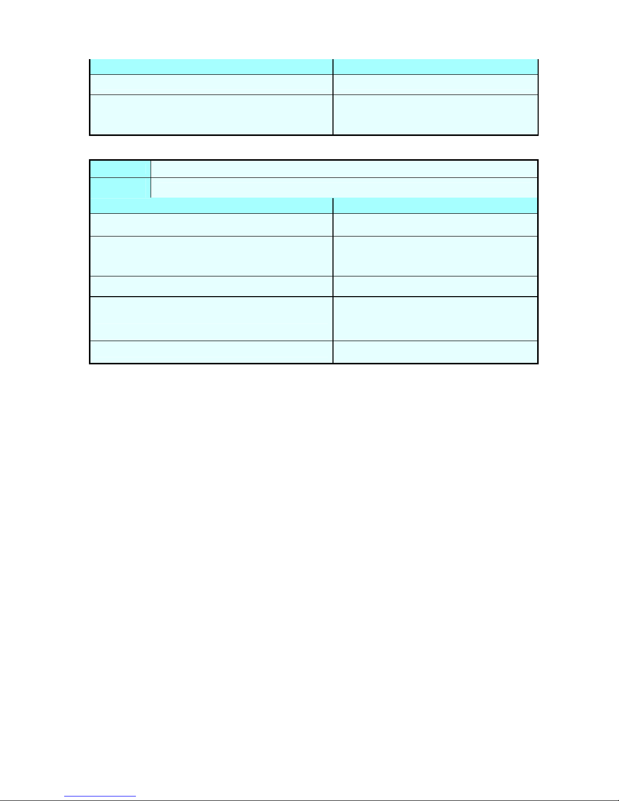
Possible cause Solution
1.Condensation due to atmospheric humidity 1.No action required
2. Try to locate the leak and check for the presence
2.Water leak
of chlorine in the water. If there is chlorine, the
heat pump must be temporarily replaced while it
is being repaired.
29
Problem:
Observat
ion:
abnormal amount of ice formed on the evaporator
the evaporator is for the most part covered in ice
Possible cause Solution
1.Insufficient air inflow
2.High water temperature
3.Incorrect setting of automatic defrost control
4.The 4-way valve is out of order
5.Not enough refrigerant
1.Check the location of the heat pump and remove
any dirt that could be present on the evaporator
2. If the pool water is already quite hot (warmer
than 29°C), the probability of ice formation
increases. Lowering the set temperature is a
possible option
3. Check the setting of the defrosting function
together with your installer.
4. Check the voltage in the electrical wiring to the
4 -way valve. If electric potential is measured,
replace the coil. If the problem persists, have the
heat pump checked by a refrigeration technician.
5. Have the heat pump checked by a refrigeration
technician.
Page 30
6.3 Overview of failure code on Display (LCD controller) – not applicable
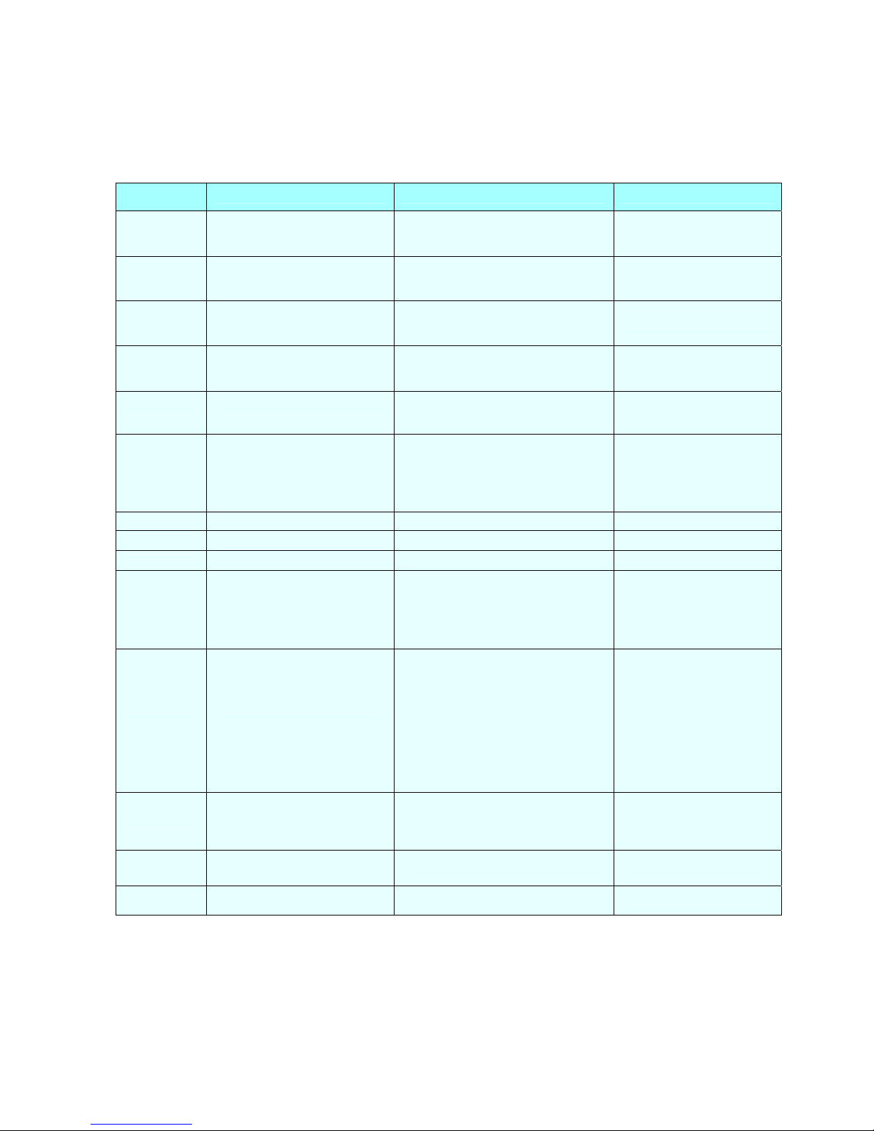
6.4 Overview of failure code on Display (LED controller)
30
Wire
controller
PP01/PP1 Inlet water temp. sensor failure
PP02/PP2 Outlet water temp. sensor failure
PP03/PP3 Coil 1 temp. sensor failure
PP04/PP4 Coil 2 temp. sensor failure
PP05/PP5 Ambient temp. sensor failure
PP06/PP6
PP07/PP7 Anti-freeze protection for cooling
PP07/PP7
PP07/PP7
EE03/EE3 Water flow switch failure
Protection/Failure Check Solution
Protection for excessive temp.
difference between water inlet &
outlet
Winter anti-freeze protection Ⅰ
Winter anti-freeze protection Ⅱ
1. Check the connection of inlet water
sensor.
2. Check if the sensor is broken.
1. Check the connection of outlet water
sensor.
2. Check if the sensor is broken.
1. Check the connection of coil 1
temperature sensor.
2. Check if the sensor is broken.
1. Check the connection of coil 2
temperature sensor. temperature
2. Check if the sensor is broken.
1. Check the connection of ambient
temperature sensor.
2. Check if the sensor is broken.
1. Check if there is any blockage in the
water circuit.
2. Check if the water flow volume is
enough.
3. Check if the water pump is working.
Refer to PP06. Refer to PP06.
No action required
No action required
1. Check if wiring connection of flow
switch is in correct position.
2. Check water flow.
3. Check if flow switch is broken.
4. Check if water pump is working.
1. Reconnect the sensor.
2. Replace the sensor.
1. Reconnect the sensor.
2. Replace the sensor.
1. Reconnect the sensor.
2. Replace the sensor.
1. Reconnect the sensor. 2.
Replace the sensor.
1. Reconnect the sensor.
2. Replace the sensor.
1. Remove the cause of the
blockage.
2. Increase the water flow
volume. 3. Repair or replace
the water pump.
1. Reconnect the wiring.
2. Increase water flow.
3. Replace flow switch.
4. Repair or replace water
pump.
1. Check if high or low pressure switch
is broken.
2. Check if refrigerant level is low (for
low pressure).
3. Ambient temp. and water inlet temp.
EE04/EE4 High / Low pressure protection
EE05/EE5
No display Defrosting
EE08/EE8 Communic ation failure Check the connection
Failure of excessive temp.
difference protection between
water inlet & outlet
is too low (for low pressure).
4. Check if there is a blockage in water
circuit or if water flow is not enough (for
high pressure).
5. Check if there is a blockage in
refrigerant circuit (for high pre ssure).
1. Check if there is enough water flow
volume.
2. Check if inlet / outlet water temp.
sensor is working.
1. Replace pressure switch.
2. Fill up with enough
refrig erant.
3. Decrease water flow.
4. Remove cause of blockage
or increase water flow.
5. Send heat pump to dealer
for detailed check.
1. Increase water flow.
2. Replace sensor.
Reconnect the connection
wire.
Page 31
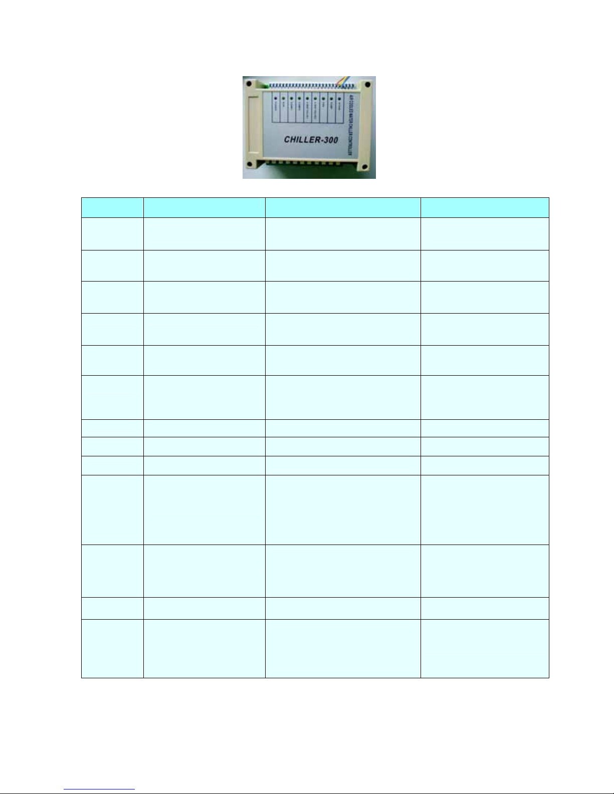
6.5 Failure code table for Chiller-300 three-phase
31
Wire
controller
PP01/PP1
PP02/PP2
PP03/PP3 Coil 1 temp. sensor failure
PP04/PP4 Coil 2 temp. sensor failure
PP05/PP5 Ambient temp. sensor failure
PP06/PP6
PP07/PP7
PP07/PP7
PP07/PP7
EE01/EE1
EE02/EE2 Malfunctions of system 2 Fault in system 2
EE03/EE3 Water flow switch failure
Protection/Failure
Inlet water temp. sensor
failure
Outlet water temp. sensor
failure
Protection for excessive temp.
difference between water inlet
& outlet
Anti-freeze protection for
cooling
Winter anti-freeze p r o tection
Ⅰ
Winter anti-freeze p r o tection
Ⅱ
High pressure protection
Low pressure protection
Check Solution
1. Check the connection of inlet water
sensor.
2. Check if the sensor is broken.
1. Check the connection of outlet water
sensor.
2. Check if the sensor is broken.
1. Check the connection of coil 1
temperature sensor.
2. Check if the sensor is broken.
1. Check the connection of coil 2
temperature sensor. temperature
2. Check if the sensor is broken.
1. Check the connection of ambient
temperature sensor.
2. Check if the sensor is broken.
1. Check if there is any blockage in the
water circuit.
2. Check if the water flow volume is
enough.
3. Check if the water pump is working.
Refer to PP06. Refer to PP06.
No action required
No action required
1. Check if high pressure switch is
broken.
2. Check if there's a blockage in the
water circuit or if water flow is not
enough.
3. Check if there is a blockage in the
refrigerant circuit.
1. Check if low pressure switch is
broken.
2. Check if refrigerant level is low.
3. Ambient temp. and water inlet temp. is
too low.
1. Check if wiring connection of flow
switch is in correct position.
2. Check if there is enough water flow.
3. Check if flow switch is broken.
4. Check if water pump is working.
1. Reconnect the sensor.
2. Replace the sensor.
1. Reconnect the sensor.
2. Replace the sensor.
1. Reconnect the sensor.
2. Replace the sensor.
1. Reconnect the sensor.
2. Replace the sensor.
1. Reconnect the sensor.
2. Replace the sensor.
1. Remove the cause of the
blockage.
2. Increase the water flow
volume. 3. Repair or replace the
water pump.
1. Replace new high pressure
switch.
2.Fill up with enough
refrigerant.
3. Remove cause of blockage or
increase water flow.
4. Send heat pump to dealer for
detailed check.
1. Replace new low pressure
switch.
2. Fill up with enough
refrigerant.
3. Send heat pump to dealer for
detailed check.
1. Check all protection points in
system 2.
1. Reconnect the wiring.
2. Increase water flow.
3. Replace flow switch.
4. Repair or replace water pump.
Page 32

EE04/EE4
EE05/EE5
High / Low pressure
protection
Failure of excessive temp.
difference protection between
water inlet & outlet
1. Check if high or low pressure switch is
broken.
2. Check if refrigerant level is low (for
low pressure).
3. Ambient temp. and water inlet temp.
is too low (for low pressure).
4. Check if there is a blockage in water
circuit or if water flow is not enough (for
high pressure).
5. Check if there is a blockage in
refrigerant circuit (for high pressure).
1. Check if there is enough water flow
volume.
2. Check if inlet / outlet water temp.
sensor is working.
32
1. Replace pressure switch.
2. Fill up with enough
refrigerant.
3. Decrease water flow.
4. Remove cause of blockage or
increase water flow.
5. Send heat pump to dealer for
detailed check.
1. Increase water flow.
2. Replace sensor.
No display Defrosting
EE08/EE8 Communication failure Check the connection Reconnect the connection wire.
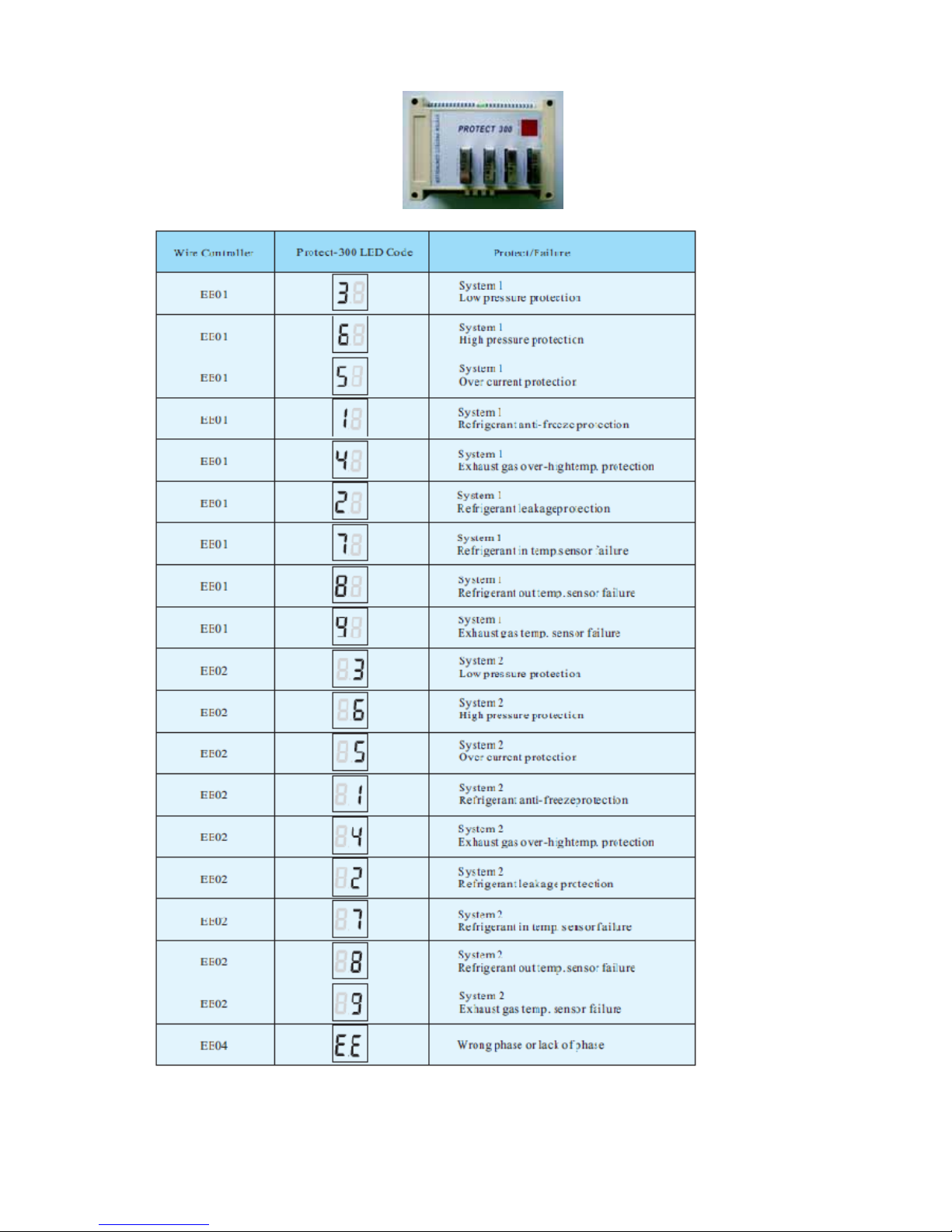
6.6 Failure code table for Protect 300
Page 33
33
Page 34
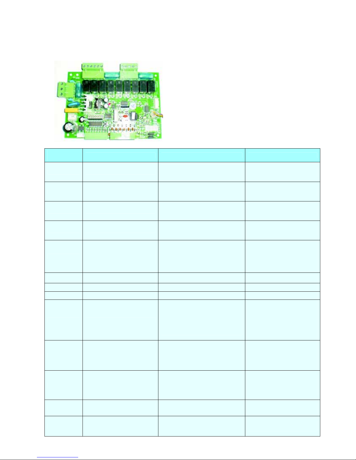
6.7 Failure code table for general PCB (single-system)
34
Wire
controller
PP01/PP1 Inlet water temp. sensor failure
PP02/PP2 Outlet water temp. sensor failure
PP03/PP3 Coil temp. sensor failure
PP05/PP5 Ambient temp. sensor failure
PP06/PP6
PP07/PP7
PP07/PP7
PP07/PP7
EE01/EE1 High pressure protection
EE06/EE6 Low pressure protection
EE03/EE3 Water flow switch failure
Protection/Failure
Protection for excessive temp.
difference between water inlet &
outlet
Anti-freeze protection for
cooling
Winter anti-freeze p r o tection Ⅰ
Winter anti-freeze p r o tection Ⅱ
Check Solution
1. Check the connection of inlet water
sensor.
2. Check if the sensor is broken.
1. Check the connection of outlet water
sensor.
2. Check if the sensor is broken.
1. Check the connection of coil
temperature sensor.
2. Check if the sensor is broken.
1. Check the connection of ambient
temperature sensor.
2. Check if the sensor is broken.
1. Check if there is any blockage in the
water circuit.
2. Check if the water flow volume is
enough. 3. Check if the water pump is
working.
Refer to PP06. Refer to PP06.
No action required
No action required
1. Check if high pressure switch is
broken
2. Check if there's a blockage in the
water circuit or if water flow is not
enough.
3. Check if refrigerant circuit jam.
1. Check if low pressure switch is
broken.
2. Check if refrigerant level is low.
3. Ambient temp. and water inlet temp.
is too low.
1. Check if wiring connection of flow
switch is in correct position.
2. Check if there is enough water flow.
3. Check if flow switch is broken.
4. Check if water pump is working.
1. Reconnect the sensor.
2. Replace the sensor.
1. Reconnect the sensor.
2. Replace the sensor.
1. Reconnect the sensor.
2. Replace the sensor.
1. Reconnect the sensor.
2. Replace the sensor.
1. Remove the cause of the
blockage.
2. Increase the water flow
volume.
3. Repair or replace the water
pump.
1. Replace with new high
pressure switch.
2. Fill up with enough
refrigerant.
3. Remove cause of blockage or
increase water flow.
4. Send heat pump to dealer for
detailed check.
1. Replace with new low
pressure switch.
2. Fill up with enough
refrigerant.
3. Send heat pump to dealer for
detailed check.
1. Reconnect the wiring.
2. Increase water flow.
3. Replace flow switch.
4. Repair or replace water pump.
EE04/EE4
EE05/EE5
Order of phases incorrect (only
for 3 phase model)
Failure of excessive temp.
difference between water inlet &
outlet
Order of phases incorrect
1. Check if there is enough water flow
volume.
2. Check if inlet / outlet water temp.
sensor is working.
Reconnect the phases in right
order.
1. Increase water flow.
2. Replace sensor.
Page 35

No display Defrosting
EE08/EE8 Communication failure Check the connection Reconnect the connection wire.
6.8 Failure code table for general PCB (dual-system) – not applicable
7. Name plate & wiring diagram
7.1 Name plate - not applicable
7.2 Wiring Diagram – not applicable
35
Page 36
36
 Loading...