

Page 1
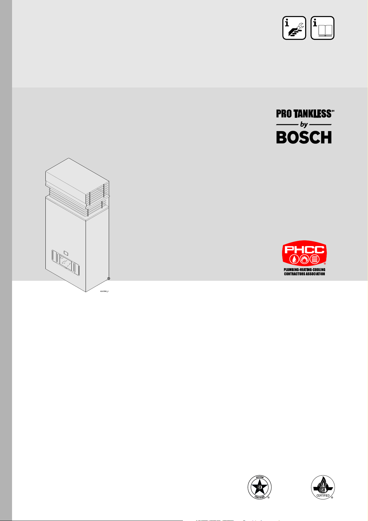
GWH 425 HNO OUTDOOR MODEL
For exterior use only
Electronic Ignition
Suitable for heating potable water only - Not approved for space heating purposes
GWH-425-HNO-N - Natural Gas
GWH-425-HNO-L - Liquefied Petroleum (LP) Gas
Warning: If the information in this manual is not
followed exactly, a fire or explosion may result
causing property damage, personal injury or death.
Do not store or use gasoline or other flammable
vapor and liquids in the vicinity of this or any other
appliance.
Improper installation, adjustment, alteration, service
or maintenance can cause injury or property
damage. Refer to this manual. For assistance or
additional information consult a qualified installer,
service agency or the gas supplier.
In the Commonwealth of Massachusetts this
product is approved only for seasonal use.
Installation must be performed by a licensed
plumber or gas fitter.
Upon completion of the installation, these
instructions should be handed to the user of the
appliance for future reference.
8 716 473 148 US (05.12) AL
What to do if you smell gas
• Close gas valve.
• Do not try to light any appliance.
• Do not touch any electrical switch; do not use any
phone in your building.
• If you cannot reach your gas supplier, call the fire
department.
• Immediately call your gas supplier from a neighbor’s
phone. Follow the gas supplier’s instructions.
•
Installation and service must be performed by a
qualified installer, service agency or the gas supplier.
Page 2
Index
Index
1 Warning 2
2 Appliance details 4
2.1 Features 4
2.2 GWH-425-HNO specifications (Technical data) 4
2.3 Unpacking the GWH-425-HNO heater 5
2.4 General rules to follow for safe operation 5
2.5 Dimensions and installation clearances 6
3 Installation instructions 7
3.1 Introduction 7
3.2 Proper location for installing your heater 7
3.3 Heater placement and clearances 8
3.4 Mounting installation 8
3.5 Gas piping & connections 10
3.6 Measuring gas pressure 12
3.7 Water connections 12
3.8 Electrical connections 13
4 Operation instructions 14
4.1 For your safety read before operating your water
heater 14
4.2 Lighting instructions 14
4.3 To turn off appliance 14
4.4 Setting the water temperature 14
4.5 Electrical diagram 16
5 Maintenance and service 17
5.1 Maintenance intervals 17
5.2 Water valve 17
5.3 Pilot 17
5.4 Main burners 17
5.5 Vent assembly 17
5.6 Mineral scale build-up 17
1 Warning
Warning: If the information in this
manual is not followed exactly, a fire or
explosion may result causing property
damage, personal injury or death.
Warning: Improper installation,
adjustment, alteration, service or
maintenance can cause injury or
property damage. Refer to this manual.
For assistance or additional information
consult a qualified installer, service
agency or the gas supplier.
Upon completion of the installation,
these instructions should be handed to
the user of the appliance for future
reference.
For your safety
Do not store or use gasoline or other flammable,
combustible or corrosive vapors and liquids in the
vicinity of this or any other appliance.
Warning: Carefully plan where you
install the heater. If a gas appliance is
not installed correctly, fatal accidents
can result from lack of air, carbon
monoxide poisoning or fire.
Warning: Place the heater in a location
where water leaks will do NO DAMAGE
to adjacent areas.
6 Troubleshooting 18
6.1 Introduction 18
6.2 Pilot will not light 18
6.3 Pilot lights but the burners will not come on 18
6.4 Hot water temp fluctuates from hot to cold 18
6.5 Water is too hot 19
6.6 Water is not hot enough 19
7 Interior components diagram and parts list 20
7.1 Interior components 20
7.2 Components diagram 21
7.3 Parts list 22
8 Protecting the environment 23
9 Fifteen Year Limited Warranty 24
2
8 716 473 148
Page 3
What to do if you smell gas
• Close gas valve.
• Do not try to light any appliance.
• Do not touch any electrical switch; do not use any
phone in your building.
• Immediately call your gas supplier from a neighbor’s
phone. Follow the gas supplier’s instructions.
• If you cannot reach your gas supplier, call the fire
department.
• Installation and service must be performed by a
qualified installer, service agency or the gas supplier.
Warning: The heater must be isolated
from the gas supply piping system
during any pressure testing of that
system at test pressures equal to or
more than 0.5 psig.
Warning
Caution: Any changes or
modifications not expressly approved
by the party responsible for compliance
could void the user’s authority to
operate the equipment.
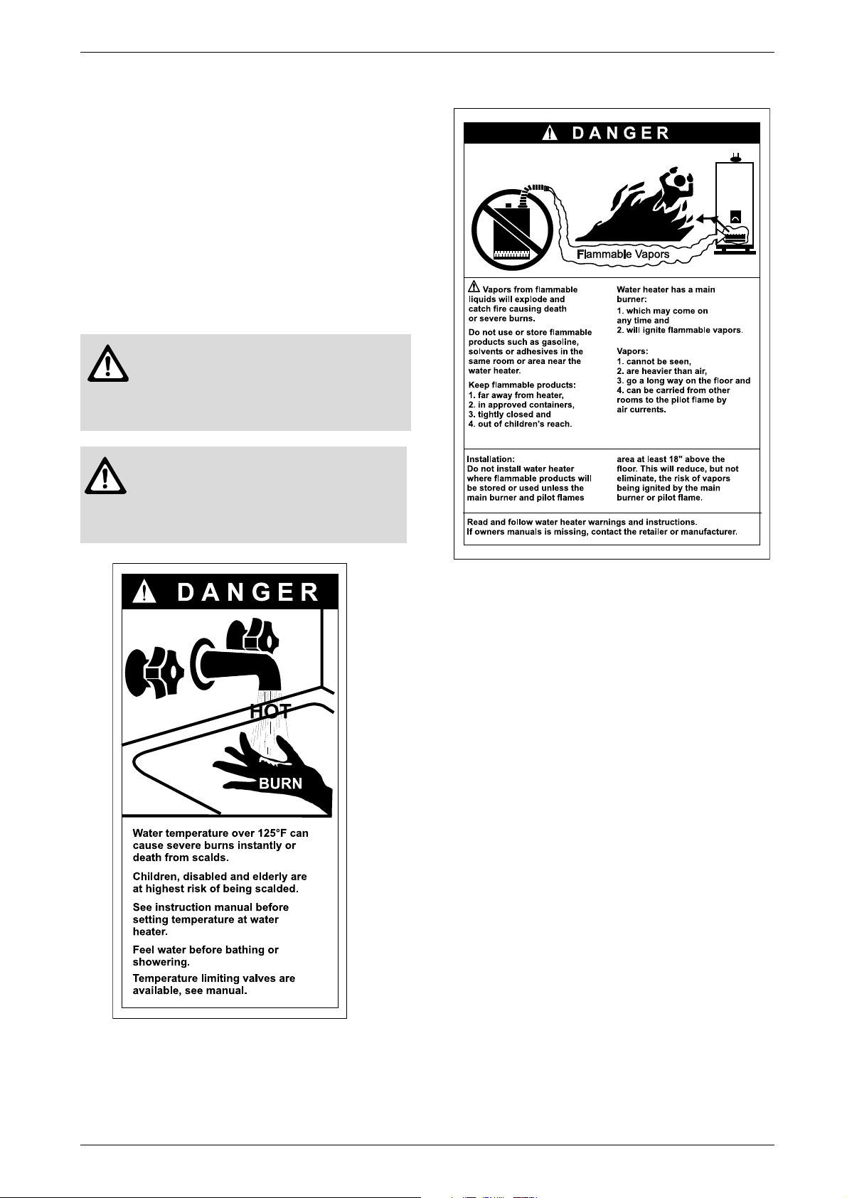
Fig. 2
Fig. 1
8 716 473 148
3
Page 4

Appliance details
i
2 Appliance details
2.1 Features
• Burner output proportional to hot water flow demand
for maximum energy efficiency
• Stainless steel burners with stabilized blue flame
• Built-in corrosion resistant draft diverter
• Adjustable water flow restrictor to ensure that water
flow demand will not exceed the heating capacity of
the heater
• Safety flame sensor at pilot burner
• Automatic overheating protection shut-off sensor
• Copper heating coils for endless supply of hot water
• Easily removable one-piece cover
• Easy one person installation
• Electronic Pilot Ignition driven by hydro-generator.
BOSCH is constantly improving its
products, therefore specifications are
subject to change without prior notice.
2.2 GWH-425-HNO specifications
(Technical data)
Approved in US/Canada
Capacity
Maximum flow rate: 3.7 GPM (14 l/min) at a 45°F
(25°C) rise.
• Water valve material: Polymer (PPS) (Polypropylene
Sulfid)
• Minimum water flow: 0.5 gallon/minute (1.9 l/m)
• Minimum recommended water pressure: 30 PSI
(2.07 bar)
• Connections:
– Bottom of heater
Dimensions
• Depth (in): 10.5” (265 mm)
• Width (in): 18.25” (460 mm)
• Height (in): 36.75” (936 mm)
• Weight: 64 pounds (29 kg).
Gas types
Natural Gas.
LP Gas
Safety devices
• Flame failure device (ionization flame rod sensor)
• Pressure relief valve (supplied with heater)
• Over heat prevention (temperature limiter).
Water resistant
IP X5 (protection against water drops).
Maximum output
101,772 Btu/h (29.8 kW)
Maximum input
117,000 Btu/h (34.3 kW)
Efficiency in %
Recovery efficiency 80%
Min. Output
28,000 Btu/h (8.2 kW)
Gas Requirement
Gas connection (inches) - ¾”
Inlet gas pressure under maximum operation*
• Propane: 10.5” - 14” water column
• Natural Gas: 5.7” - 14” water column.
* To measure Gas Pressure, see Measuring Gas
Pressure, chapter 3.6.
Water
• Hot water connection (inches) - ½”
• Cold water connection (inches) - ½”
4
8 716 473 148
Page 5

Appliance details
2.3 Unpacking the GWH-425-HNO
heater
This heater is packed securely.
Before installing the unit, be certain you have the
correct heater for your type of Gas - Propane or
Natural Gas. Identification labels are found on the
shipping box, and on the rating plate which is located on
the right side panel of the cover.
The box includes:
• Pressure relief valve
• Heat shield
• Mounting screws
• Product registration card
• Installation manual.
Do not lose this manual, there is a charge for a
replacement.
Please complete and return the enclosed product
registration card.
The GWH-425-HNO is not approved or designed
for:
• Manufactured (mobile) homes, RV's or boats
• Heating or other recirculating/pumping applications*
• Solar/preheat backup or high temperature booster
use
* This includes domestic hot water circulator pump loop
systems that may previously exist in a home hot water
system. The use of a small electric mini-tank (4-6 gallon
size) should be used for this application; when
designed so the pump will circulate the hot water in the
mini-tank only and through the building's hot water
return loop (timed or thermostatic controlled operation
of the pump is commonly done). The GWH-425-HNO
should be plumbed in line before the mini-tank water
heater, contact BBTNA if further instruction is needed.
2.4 General rules to follow for safe
operation
B 1. You should follow these instructions when you
install your heater. In the United States: The
installation must conform with local codes or, in the
absence of local codes, the National Fuel Gas Code
ANSI Z223.1/NFPA 54.
In Canada: The Installation should conform with
CGA B149.(1,2) INSTALLATION CODES and /or
local installation codes.
B 2. Carefully plan where you install the heater. Proper
clearances must be followed.
B 3. The appliance must be isolated from the gas
supply piping system by closing its individual manual
gas shutoff valve (not supplied with heater) during
any pressure testing at pressures in excess of ½ Psig
(3.5 kPa).
The appliance and its gas connection must be leak
tested before placing the appliance in operation.
B 4. Keep water heater area clear and free from
combustibles and flammable liquids. Do not locate
the heater over any material which might burn.
B 5. Correct gas pressure is critical for the optimum
operation of this heater. Gas piping must be sized to
provide the required pressure at the maximum output
of the heater, while all the other gas appliances are in
operation. Check with your local gas supplier, and
see the section on connecting the gas supply.
B 6. Should overheating occur or the gas supply fail to
shut off, turn off the gas supply at the manual gas
shut off valve, on the gas line. Note: manual gas
shutoff valve is not supplied with the heater.
B 7. Do not use this appliance if any part has been
underwater. Immediately call a qualified service
technician to inspect the appliance and to replace
any part of the control system and any gas control
which has been underwater.
8 716 473 148
5
Page 6
Appliance details
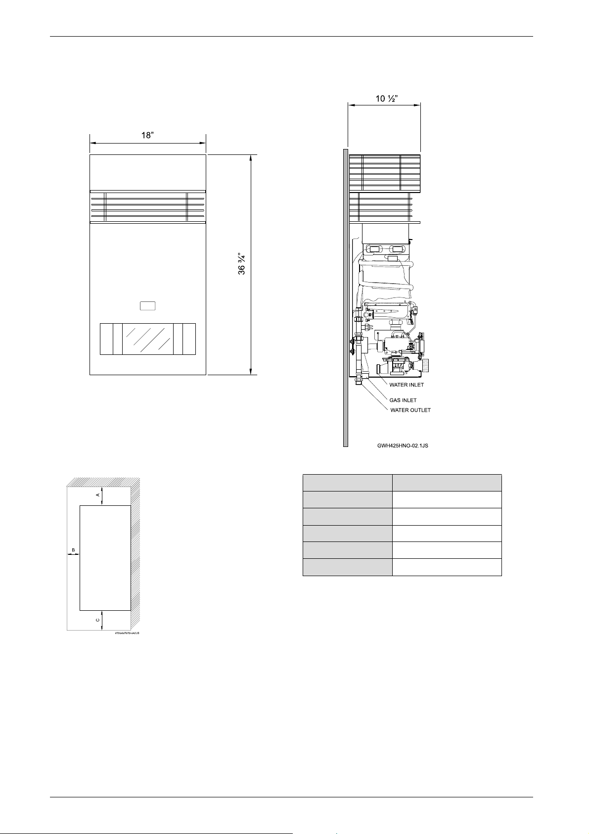
2.5 Dimensions and installation clearances
Fig. 3 Dimensions
Fig. 4 Minimum clearances
Model GWH-425-HNO
TOP (A) 3 ft.
FRONT (B) 4 ft.
BACK 0”
SIDES 4 ft.
BOTTOM (C) 1 ft.
Table 1 Minimum clearances
6
8 716 473 148
Page 7
3 Installation instructions
Installation instructions
3.1 Introduction
Please follow these instructions. Failure to follow
instructions may result in:
B Damage or injury.
B Improper operation.
B Loss of warranty.
Please contact BBT North America with any questions.
3.2 Proper location for installing your
heater
Carefully select the location of the water heater.
Follow the guidelines below:
B 1. Locate the heater where an adequate gas line size
and plumbing connections are feasible and
convenient.
B 2. The hot water lines should be kept short to save
energy. Centrally locating the water heater is best. It
is always best to have hot water lines insulated to
prevent the possibility of any freeze damage.
B 3. The water in this heater is cold and always remains
cold except for the times that hot water is being used.
The heater is equipped with freeze prevention
equipment that will operate and prevent freezing of
the water in the heater to 5°F with no wind chill.
Electrical power must be maintained to the heater to
allow this to function.
Danger: Flue gases will be released
through the vent cap. Flue gas is very
hot and contains carbon monoxide. The
heater cannot be installed indoors. To
prevent risk of fire and poisoning by
carbon monoxide, assure all clearances
indicated in manual.
Danger: Surface temperature around
vent cap is less than 140°F, except
highest top surface of vent cap may
reach 300°F.
Danger: Do not place or store any
combustible material within 5 feet of the
appliance. Risk of fire could be caused
by hot flue gas.
Warning: Flammable materials,
gasoline, pressurized containers, or any
other items or articles that are potential
fire hazards must NOT be placed on or
adjacent to the heater. The appliance
area must be kept free of all
combustible materials, gasoline and
other flammable vapors and liquids.
WARNING: Proper insulation of the
water lines below the heater is required
if below freezing temperatures, below
32°F, are ever anticipated!
Danger: If the temperature drops
below 32°F, freeze damage to the water
heater itself must be prevented by
turning off the power to the heater, then
disconnecting the plumbing connections, as well as removing the drain
plug and introducing short bursts of
compressed air (20-40 psi) through the
heater's connections. This will remove
the residual water in the horizontal
pipes and water valve.
Danger: Keep children away as the top
of the water heater vent cap will get very
hot during operation. Install in a place
that prevents the top of the heater being
reached by small children.
8 716 473 148
7
Page 8
Installation instructions
i
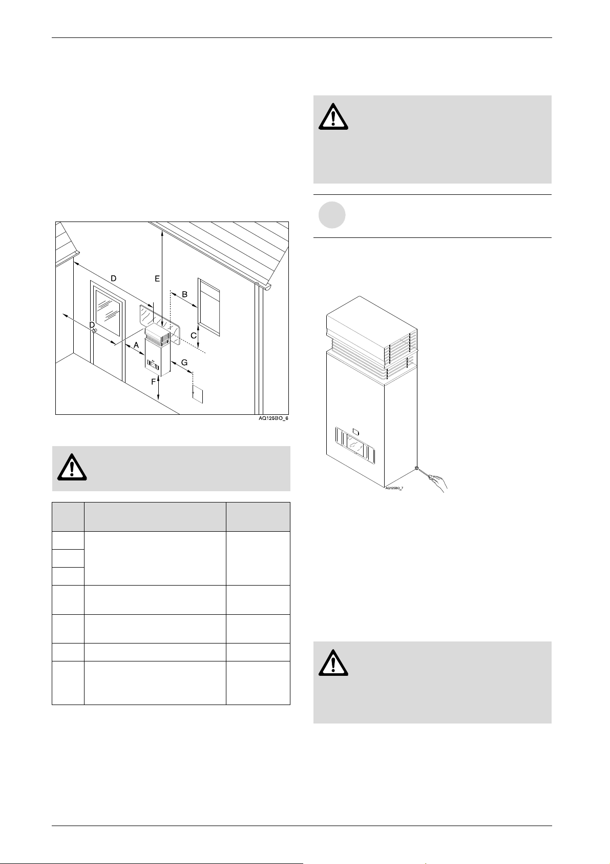
3.3 Heater placement and clearances
The GWH-425-HNO is design certified for installation
directly on a combustible wall. (see 3.4 Mounting
installation) For installation on vinyl siding see Fig. 7.
Keep the area below the heater free of combustible
material.
Minimum clearances
If the appliance is installed under an overhang, there
must be a 36” clearance from the top of the appliance
and the mounting area must be open in front and on the
sides of the appliance.
3.4 Mounting installation
Warning: before starting installation:
B check that there are no loose parts
inside the appliance
B ensure that gas pipe, gas valve, and
burner have no damage and are
properly fitted.
Front cover should be removed in order to
inspect components visually (see
instructions below).
To remove front cover.
B Loosen the two screws located on the sides of the
front panel, see Fig. 6.
Fig. 5
Danger: The top of the kit will get hot
due to the flue gases. Install away from
children.
Ref. Description
A Directly below or from an
B
C
D
E
F Above ground ≥ 1 ft
G
Table 2 Clearances
opening; operable windows,
doors and any fresh air
openings
From any adjacent wall or tall
shruberry
Below a gutter, sanitary
pipework, eaves or overhang
From a gas meter, gas
regulator, electrical box or
another 425-HNO heater.
Min.
distances
≥ 4 ft
≥ 4 ft
≥ 3 ft
≥ 3 ft
Fig. 6 Remove front cover
B Ensure that the flue terminal is clear of any
combustible material.
B After inspection, replace front cover and tighten
screws.
B Install only on an external wall, as close as possible
to the most frequently used hot tap (note clearances
in chapter 3.3.
B If the unit is to be installed on a combustible surface
use the enclosed heat shield (see Fig. 5).
Warning: Do not mount heater directly
to vinyl siding. With vinyl siding
surfacing, a 6' x 4' area of the siding
must first be covered or replaced with
wood or other non-plastic made
material. See Fig. 7.
8
8 716 473 148
Page 9
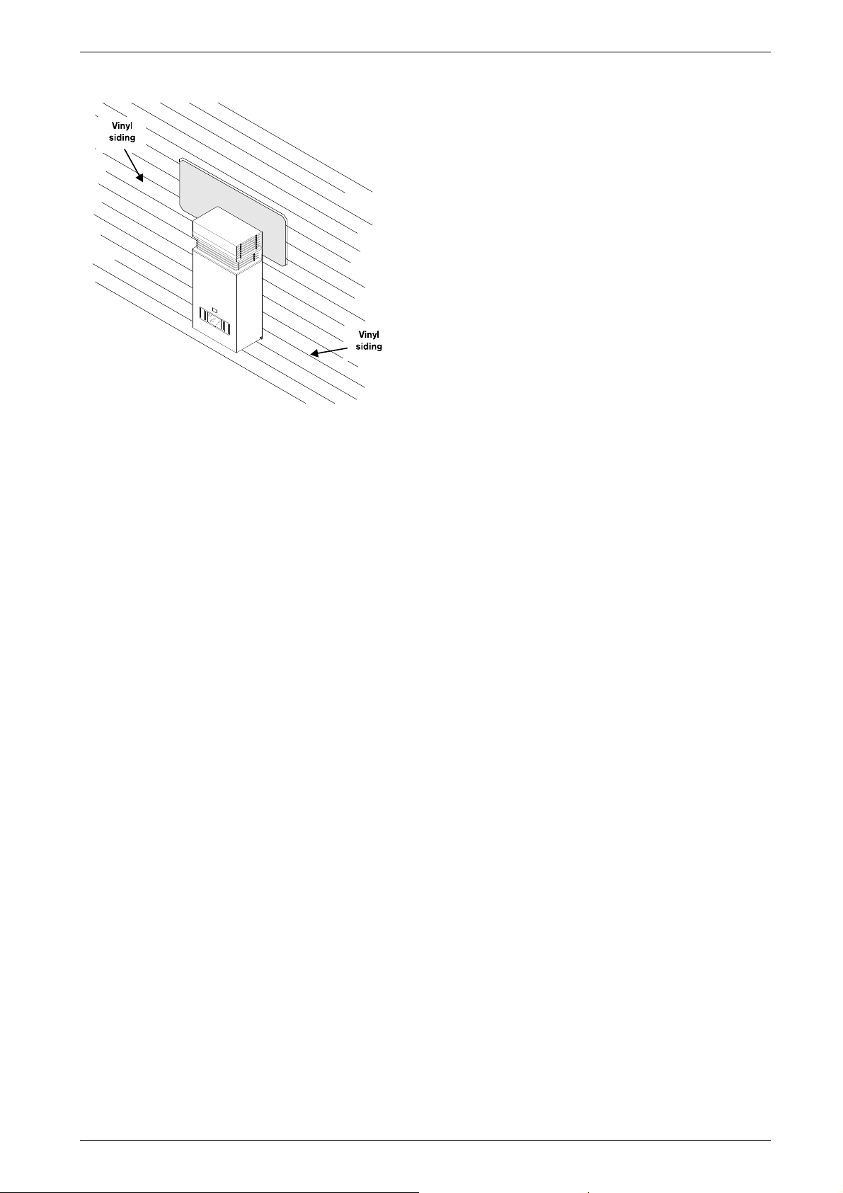
Fig. 7
B Secure heater to wall using enclosed mounting
screws. Use mounting template for proper screw
location.
B Locate head of screw in the key hole of the top
mounting bracket.
Installation instructions
Vent Safety System
The GWH-425-HNO will shut down if the intake or
exhaust louvers on the vent cap are blocked for any
reason; see troubleshooting section on page 18.
8 716 473 148
9
Page 10
Installation instructions
3.5 Gas piping & connections
Before connecting the gas supply, check the rating
plate on the right side of the heater to be sure that the
heater is rated for the same gas to which it will be
connected.
In the United States: The installation must conform with
local codes or, in the absence of local codes, the
National Fuel Gas Code ANSI Z223.1/NFPA 54.
In Canada: The Installation should conform to CGA
B149 INSTALLATION CODES and/or local installation
codes.
Note: The 425 HNO comes with a gas pressure
regulator installed. Disconnecting or altering the gas
pressure regulator will be a violation of CSA
certification of the unit. The regulator supplied with the
heater is preset for the gas shown on the rating plate to
the correct pressure. It is an appliance level regulator
designed for (low inlet) pressure (less than 1/2 Psig or
14" W.C.).
Warning: DO NOT connect to an
unregulated or high pressure propane
line or to a high pressure commercial
natural gas line.
Danger: If you have a leak, shut off the
gas. Tighten appropriate fittings to stop
leak. Turn the gas on and check again
with a gas leak detection solution.
Never test for gas leaks using a match
or flame.
HIGH ALTITUDE INSTALLATION
The pressure regulator provided with the heater is
adjusted to deliver the proper gas pressure (as
indicated on the rating plate and in the manual for
altitude up to 2000 feet (660 meters) above sea level.
On appliances being installed above 2000 ft (660
meters) elevation, the inlet gas pressure should be set
at installation to the value shown below.
Note: The gas pressures specified below refer to
pressures taken at the pressure tap on the gas inlet pipe
just above the regulator. See chapter 3.6 for measuring
gas pressure.
MAXIMUM INLET GAS FLOW PRESSURE SETTING
Altitude
0’ - 2 000 ft 5.7” 10.5”
Nat. Gas
inches W.C.
Liquid Propane
inches W.C.
Warning: The heater must be isolated
from the gas supply piping system
during any pressure testing of that
system at test pressures equal to or
more than 0.5 psig. If overpressure has
occurred, such as through improper
testing of the gas lines or malfunction of
the supply system, the gas valve must
be checked for safe operation
GAS CONNECTIONS
B Install a manual gas shut off valve, on the gas supply
line.
B Install a union when connecting gas supply.
B The minimum diameter required for any appliance
connector used is ¾”.
B National Fuel Gas Code requires that a sediment
trap (drip leg) be installed on gas appliances not so
equipped. The drip leg must be accessible and not
subject to freezing conditions. Install in accordance
with the recommendations of the serving gas
supplier.
2 000 ft - 4 500 ft 4.6” 8.4”
Table 3 Above 4.500 ft consult your local gas provider
GAS LINE SIZING
The gas supply piping should be sized according to the
applicable code for a maximum draw of 117,000 BTUH.
Measure the length of gas supply line and use the tables
in Fig. 8 or the gas line manufacturer’s sizing tables to
determine the pipe diameter necessary to
accommodate the BTU demand of the unit. If there are
more gas drawing appliances on the line, size the gas
line according to the total maximum amount of BTU
draw for all appliances.
Note: Under sizing the gas line may result in diminished
output and improper operation. See chapter 3.6 for the
procedure to confirm gas pressure.
When connections are made, check for gas leaks at all
joints. Apply some gas leak detection solution to all gas
fittings. Bubbles are a sign of a leak. A combustible gas
detector may also be used to detect for leaks.
10
8 716 473 148
Page 11
Installation instructions
Follow boxed numbers for piping just one GWH-425-HNO (example: ¾” B.I. Natural Gas pipe for 20 ft (6.1m).
will handle 190,000 btu’s (55.7 kWh). For multiple appliances combine the total btu input load and then refer to
applicable chart below.
* EHD = Equivalent Hydraulic Diameter. The greater the
value of EHD, the greater the gas capacity of the tubing
.
Maximum Capacity of Semi-Rigid copper Tubing in
Thousands of BTU per Hour of Undiluted Liquefied
Petroleum Gases (at 11 inches Water Column Inlet
Pressure).
(Based on a Pressure Drop of 0.5 Inch Water Column)
* Source National Fuel Gas Code NFPA 54, ANSI Z223.1
- No Additional Allowance is necessary for an ordinary
number of fittings
FOR LP GAS
Maximum Capacity of Pipe in Thousands of BTU per Hour of Undiluted Petroleum Gases (at 11 inches Water Column Inlet
Pressure) (Based on a Pressure Drop of 0.5 Inch Water Column).
* EHD = Equivalent Hydraulic Diameter. The greater the
value of EHD, the greater the gas capacity of the tubing.
Nominal
Iron Length of Black Iron Pipe, Feet
Pipe Internal
Size Diameter
inches inches 10 20 30 40 50 60 70 80 90 100 125 150 175 200
1/4 0.364 32 22 18 15 14 12 11 11 10 9 8 8 7 6
3/8 0.493 72 49 40 34 30 27 25 23 22 21 18 17 15 14
1/2 0.622 132 92 73 63 56 50 46 43 40 38 34 31 28 26
3/4 0.824 278 190 152 130 115 105 96 90 84 79 72 64 59 55
1 1.049 520 350 285 245 215 195 180 170 160 150 130 120 110 100
1 1/4 1.380 1050 730 590 500 440 400 370 350 320 305 275 250 225 210
1 1/2 1.610 1600 1100 890 760 670 610 560 530 490 460 410 380 350 320
2 2.067 3050 2100 1650 1450 1270 1150 1050 990 930 870 780 710 650 610
Tube
size,
inches EHD*
10 20 30 40 50 60
1/2
18 EHD
82 58 47 41 37 34
3/4
23 EHD
161 116 96 83 75 68
1
30 EHD
330 231 188 162 144 131
1 1/4
37 EHD
639 456 374 325 292 267
Length of Flexible Corrugated Stainless Steel Tubing (CSST), Feet
Nominal
Iron pipe
Black Iron Pipe
size
Length of pipe, Feet
inches
10 20 30 40 50 60 70 80 90 100 125 150
1/2 275 189 152 129 114 103 96 89 83 78 69 63
3/4 567 693 315 267 237 217 196 185 173 162 146 132
1 107 732 590 504 448 409 378 346 322 307 275 252
1 1/4 220 149 121 103 913 834 771 724 677 630 567 511
1 1/2 330 229 185 155 141 127 118 108 102 976 866 787
2 622 433 346 299 264 239 220 204 192 1811 1606 1496
Tube
size
inches EHD*
10 20 30 40 50 60
1/2
18 EHD
129 91 74 64 58 53
3/4
23 EHD
254 183 151 131 118 107
1
30 EHD
521 365 297 256 227 207
1 1/4
37 EHD
971 661 528 449 397 359
Length of Flexible Corrugated Stainless Steel Tubing (CSST), Feet
Copper (LP gas only)
Outside Length of Tubing, Feet
diameter
Inch 10 20 30 40 50 60 70 80 90 100
3/8 39 26 21 19
_ _ _ _ _ _
1/2 92 62 50 41 37 35 31 29 27 26
5/8 199 131 107 90 79 72 67 62 59 55
3/4 329 216 181 145 131 121 112 104 95 90
FOR NATURAL GAS
Maximum Capacity of pipe in Cubic Feet of Gas per Hour for Gas Pressure of 0.5 Psig or less and a Pressure drop
of 0.3 in Water Column (0.75mbar).(Based on a 0.60 Specific Gravity Gas) Btu numbers given in thousands.
Copper tubing is prohibited for use with Natural Gas in the Commonwealth of Massachusetts and not recommended
elsewhere.
Fig. 8
8 716 473 148
11
Page 12
Installation instructions
3.6 Measuring gas pressure
Connecting manometer
B Shut off gas.
B Remove front cover and locate inlet gas pressure
measuring point on the right side of the gas valve.
B Loosen screw from test point on the left side of gas
valve and connect manometer tube on test point.
Static pressure test
B Turn gas supply back on.
B Operate all other gas appliances on same gas piping
system at maximum output.
B Record static gas pressure reading on back page of
manual.
Operating pressure test
B Run high hot water flow rate.
B Set flow control knob fully clockwise.
B Set slide control to the right.
B Record operating gas pressure reading on back
page of manual.
Gas pressures lower than 5.7" W.C. for Natural Gas or
10.5" W.C. for LP Gas will result in insufficient degree
rise to the hot water being used, and must be corrected.
See Gas Line Sizing under chapter 3.5.
reversed, the heater will not function. Be certain there
are no loose particles or dirt in the piping. Blow out or
flush the lines before connecting to the water heater.
Full port valves should be installed on both the cold
water supply and hot water outlet lines to facilitate
servicing the heater (see Fig. 9). For installation on a
private well system with the use of a pressure tank, the
lowest pressure range setting recommended is 30-50
psi (2.07 and 3.45bar).
Connecting the pressure relief valve (PRV)
A listed pressure relief valve supplied with the heater
must be installed at the time of installation. No valve is
to be placed between the PRV and the heater. No
reducing coupling or other restriction may be installed
in the discharge line. The discharge line must be a
minimum of 4” above a drain and installed such that it
allows complete drainage of both the PRV and the line.
The location of the PRV must be readily accessible for
servicing or replacement, and be mounted as close to
the water heater as possible. See Fig. 9. To install the
PRV, a suitable fitting connected to an extension on a
“T” fitting can be sweated to the hot water line.
Support all piping.
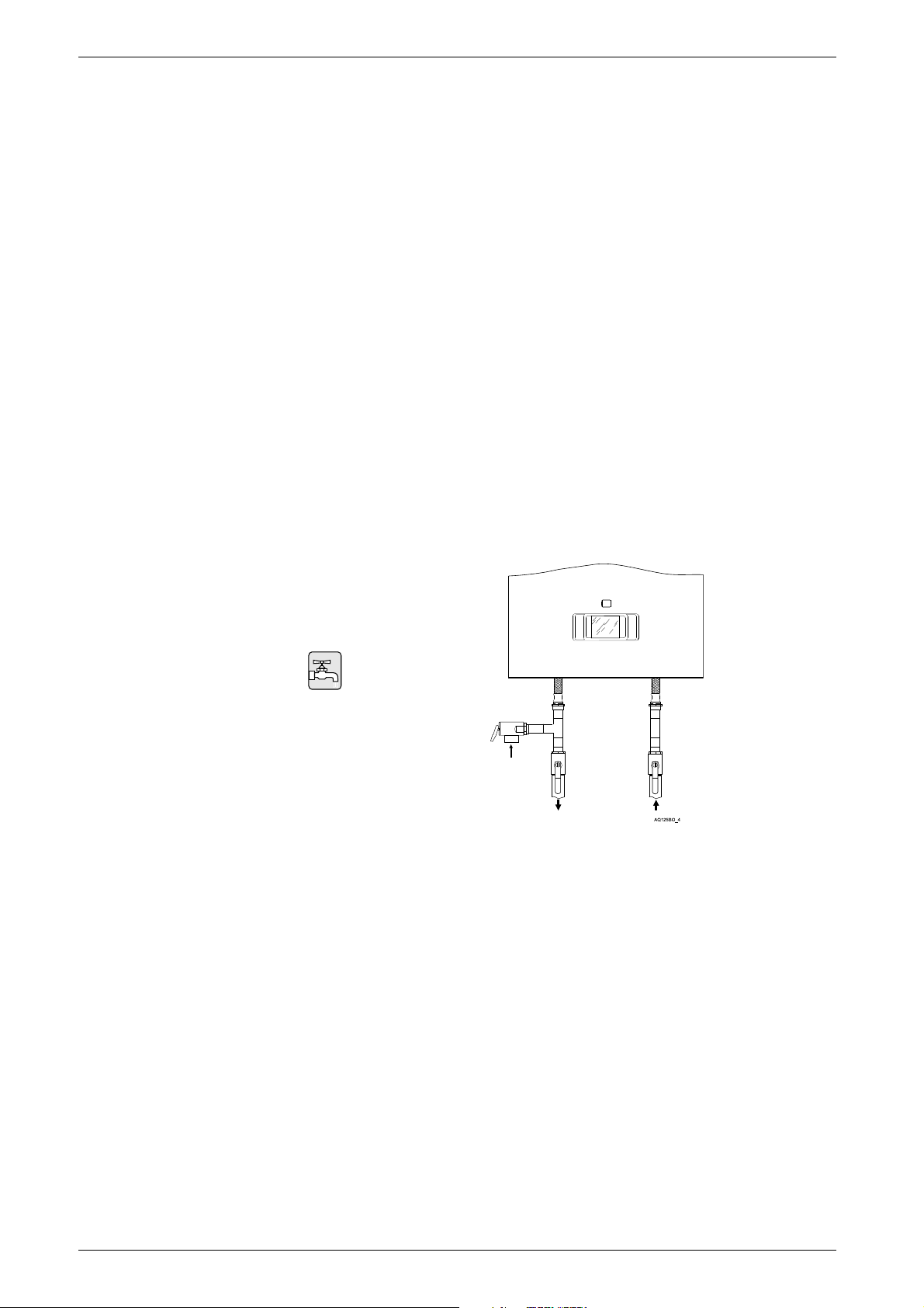
3.7 Water connections
When facing the heater, the ½” cold water inlet is on the
bottom right and the hot water outlet is on the bottom
left.
B INSTALL A UNION WHEN CONNECTING
WATER PIPE TO FACILITATE ANY
NECESSARY CLEANING AND SERVICING.
Although water piping throughout your structure may be
other than copper, we recommend that copper piping
or suitably rated stainless steel flex line piping be used
for at least three feet before and after the heater (follow
local codes if more stringent). Never sweat any rigid
piping directly to or beneath the water connections,
damage can occur to the internal water valve from
heating of the pipe. Plastics or other PEX type plumbing
line materials are not recommended for connecting
directly to the water heater. Keep water inlet and outlet
pipes to no less than ½" (12.7mm) diameter to allow the
full flow capacity.
It is recommended that all water piping below the
heater be properly insulated to avoid heat loss. If
below freezing temperatures are ever anticipated where
the heater is located, insulation material is required and
must be capable of protecting the piping from freezing.
The freeze protection that is equipped within the heater
will not prevent any freeze damage to the exterior water
piping.
If the cold and hot connections to the heater are
Fig. 9 Plumbing Connections and Pressure Relief
Valve
12
8 716 473 148
Page 13
3.8 Electrical connections
Warning: Confirm that the water
heater is appropriately grounded and
that the installation meets all electrical
codes. Outdoor electrical outlets have
special requirements.
Warning: For safety reasons,
disconnect the power supply to the
heater before any service or testing is
performed.
Warning: This heater must be
electrically grounded in accordance
with the most recent edition of the
National Electrical Code. NFPA 70. In
Canada, all electrical wiring to the
heater should be in accordance with
local codes and the Canadian Electrical
Code, CSA C22.1 Part 1. Do not rely
on the gas or water piping to ground the
metal parts of the heater.
Installation instructions
The 425 HNO requires an electrical power supply from
a 120VAC 60Hz circuit and must be properly
grounded.
A means for switching off the 120VAC power supply
must be provided.
Warning: The heater is equipped with
freeze prevention equipment that will
operate and prevent freezing of the
water in the heater to 5°F with no wind
chill. Electrical power must be
maintained to the heater to allow this to
function. WARNING: Proper
insulation of the water lines below
the heater is required if below
freezing temperatures, below 32°F,
are ever anticipated.
8 716 473 148
13
Page 14
Operation instructions
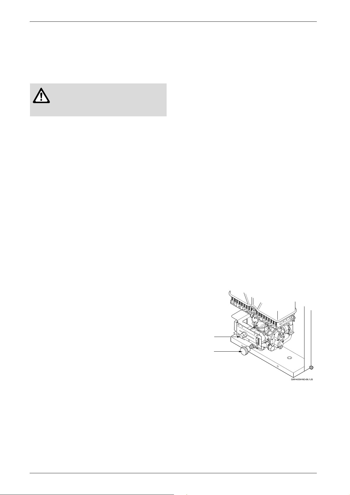
GAS CONTROL
SLIDE
TEMPERATURE
ADJUSTMENT KNOB
4 Operation instructions
4.1 For your safety read before
operating your water heater
Warning: If you do not follow these
instructions exactly, a fire or explosion
may result causing property damage,
personal injury or loss of life.
A. This appliance is equipped with electronic ignition for
lighting the main burners. When turning the heater on,
follow these instructions exactly.
B. What to do if you smell gas.
WHAT TO DO IF YOU SMELL GAS
B Do not try to light any appliance.
B Do not touch any electric switch; do not use any
phone in your building.
B Immediately call your gas supplier from a neighbors
phone. Follow the gas supplier’s instructions.
B If you cannot reach your gas supplier, call the fire
department.
C. Use only your hand to turn the on/off control switch.
Never use tools. Follow these instructions exactly. If
control switch is jammed, close the gas supply and call
a qualified service technician. Attempted forceful repair
may result in a fire or explosion.
D. Do not use this appliance if any part has been under
water. Immediately call a qualified service technician to
inspect the appliance and to replace any part of the
control system and any gas control which has been
under water.
some ignition delay. In that case, repeatedly open and
close the hot water tap in order to restart the ignition
process until all the air has been purged.
B 8. Turn the hot water faucet on to the minimum flow
rate required to activate the heater. The automatic
ignition system first ignites the safety pilot burner
which then ignites the main burner in about 4
seconds.
B 9. The pilot flame will extinguish 10-30 seconds after
the burners come on. The burners will remain on until
the hot water tap is turned off.
B 10. For maximum power, slide gas valve button all the
way to the right.
4.3 To turn off appliance
B Turn off the manual gas shut off valve on the supply
line to the heater. See Fig. 11.
B Turn power switch to the off (O) position.
B Drain water lines if unit will sit for a long period of
time.
4.4 Setting the water temperature
The 425 HNO has a gas control that modulates burner
input in response to flow. Its purpose is to ensure that
the hot water temperature will remain steady, although
the water flow demand might vary. The output
temperature can be adjusted with either the
temperature adjustment knob or the gas control slide.
4.2 Lighting instructions
B 1. STOP! Read the previous safety information.
B 2. Turn off power supply to heater.
B 3. Open the cold water inlet supply to the heater fully.
B 4. Open a hot water faucet to permit the water to fill
the heater and the piping and to eliminate the air
trapped in the system.
B 5. Close the hot water faucet after the water flows
freely and all the air has escaped from the system.
The water heater is now ready to operate.
B 6. Open gas isolation valve. Wait five (5) minutes. If
you smell gas, STOP! Follow “B” in the safety information above. If you do not smell gas, go to the next
step.
B 7. Set the switch (located behind the sliding viewer
window on the front panel strip) to the “ON” position.
In this position, the water heater is ready to use.
Note: On first time initial installation, existence of air in
the gas supply line and
14
in the water line may cause
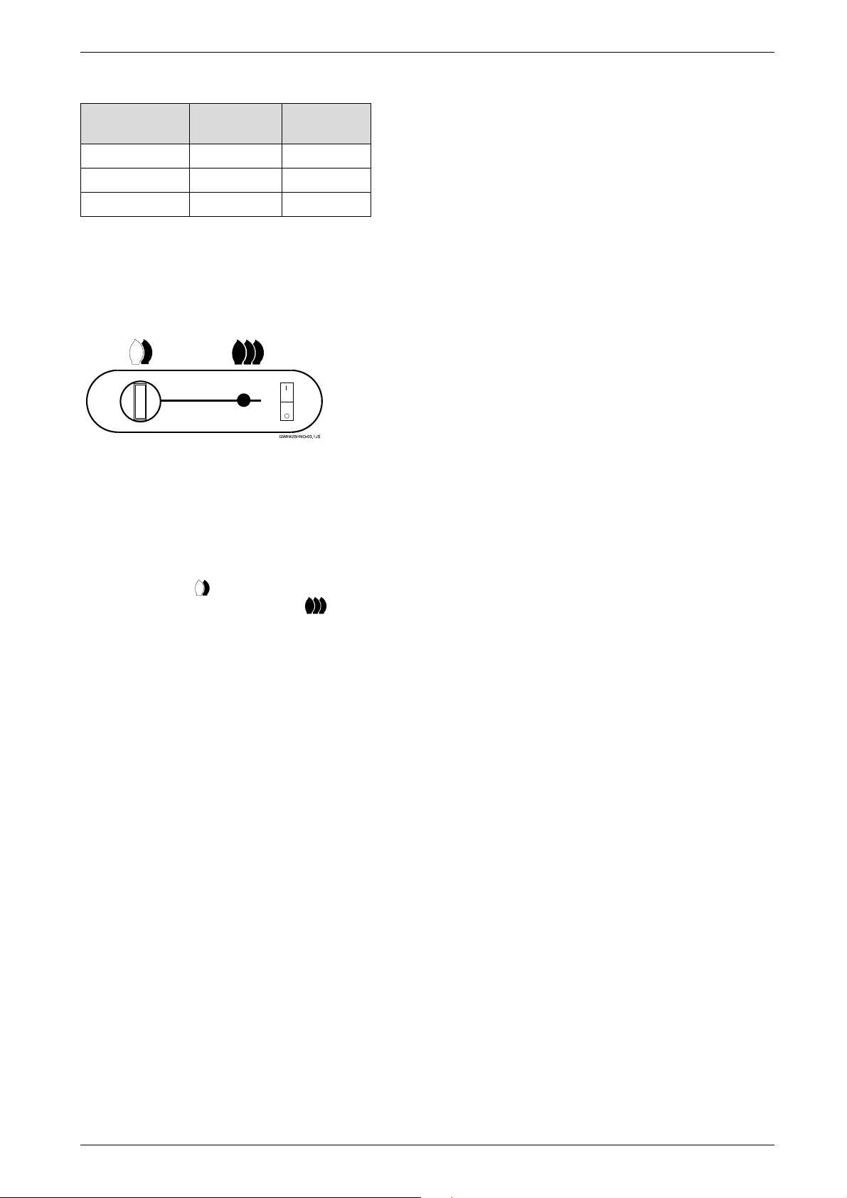
Fig. 10 Temperature Adjustment Controls
Temperature adjustment knob
The temperature adjustment knob on the front bottom of
the heater (see Fig. 10) adjusts temperature by
adjusting flow capacity. See table 4 for details.
8 716 473 148
Page 15
Operation instructions
Knob
position
clockwise
counter-
clockwise
Degree rise 90°F 45°F
Activation rate 0.5 GPM 1.1 GPM
Max flow rate 2.0 GPM 3.7 GPM
Table 4 Clearances
As the temperature adjustment knob is turned counterclockwise, the output temperature will lower and the
activation rate will be raised. Turning the knob
clockwise will raise the temperature and lower the
activation rate.
Fig. 11
Gas control slide button
The gas control slide button adjusts temperature by
adjusting how much gas is allowed to flow to the
burners.
As the slide is adjusted to the left, the output
temperature will lower, with the lowest setting being the
one flame position . The hottest position is the three
flame position all the way to the right .
8 716 473 148
15
Page 16
Operation instructions
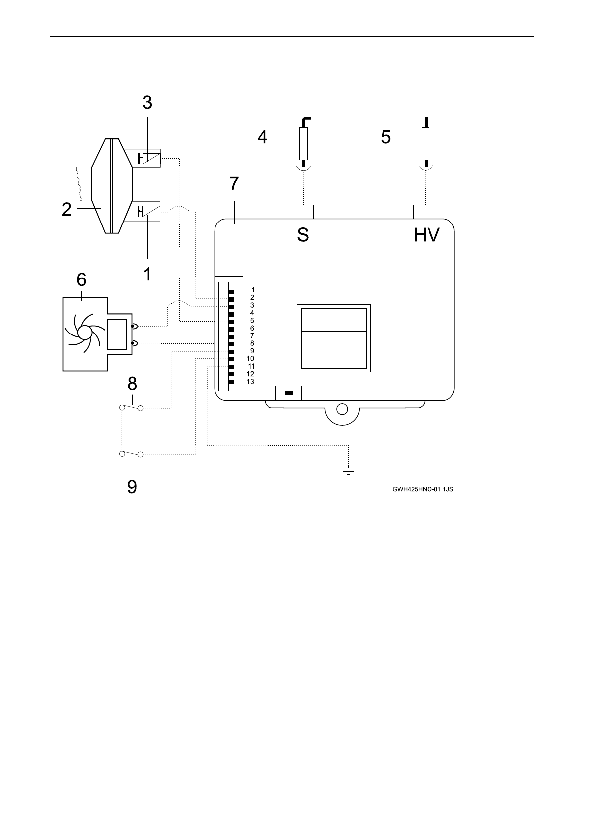
4.5 Electrical diagram
Fig. 12 Electrical scheme
1 Burner electrovalve
2 Gas control valve
3 Pilot electrovalve
4 Flame sensor
5 Pilot electrode
6 Hydro-generator
7 Electronic control box
8 Temperature limiter
9 on/off switch
16
8 716 473 148
Page 17

5 Maintenance and service
Maintenance and service
5.1 Maintenance intervals
The 425 HNO requires periodic maintenance. The
below time maintenance intervals should kept the unit
operating for many years.
Every year
B Inspect inlet water filter screen ( 5.2)
B Inspect pilot assembly and flame ( 5.3)
B Inspect burner assembly ( 5.4)
B Inspect vent assembly ( 5.6)
Every 2 years
B Lubricate and clean water valve ( 5.2)
Every 3 to 5 years
B Rebuild water valve ( 5.2)
B Clean pilot assembly and clean or replace orifice
( 5.3)
5.2 Water valve
The water valve is the main control that tells the heater
to fire. If the periodic maintenance is neglected, more
costly damage may occur over time.
Inspecting inlet water filter screen
Shut off the installer supplied cold water supply valve.
Disconnect water pipe going to the back of the water
valve. Remove filter from back of water valve. Clean the
filter and inspect for damage. Replace if the filter is at all
damaged. Inspect the top of the water valve for signs of
a water leak or corrosion. If present, rebuild the water
valve. (See below).
Lubricating the water valve
A more detailed instruction is available on our website
at www.boschpro.com. Shut off all water to the unit and
disconnect water pipe going to the back of the water
valve. Disconnect water pipe going to heat exchanger
by removing pin and pulling pipe out. Loosen two set
screws at the base of the gas valve and drop the water
valve down. Separate the two halves by removing 5
screws on the top of the water valve. Apply lithium or
faucet and valve grease to the pushrod (see Fig 14,
pos. 31). Inspect and clean the venturi (see Fig 14,
pos. 49).
Rebuilding the water valve
Several parts within the water valve should be replaced
every 3-5 years. The parts list and instruction can be
found on our website at www.boschpro.com.
5.3 Pilot
Inspecting pilot
The pilot should burn with a clean sharp blue flame. The
flame should fully envelope the bend of the flame sensor
rod. If it does not, clean the pilot assembly per
procedure below.
Cleaning pilot assembly
Disconnect the flame sensor rod cable and the igniter
cable by pulling gently down. Remove two screws holding pilot assembly in place. Loosen compression fitting
and remove pilot assembly. NOTE: The orifice sits on
top of the compression fitting DO NOT LOSE. Polish
flame sensor rod and igniter tip with emery cloth. Clean
out pilot assembly and orifice with carburetor cleaner. If
heater is an LP unit, replace orifice. Caution: Do not
enlarge orifice.
5.4 Main burners
The main burner flames should be blue, with a more
intense blue cone in the center core. Yellow flames
could be a sign of wrong size gas orifices or dirty
burners, or a blockage on the heat exchangers fins. If
some burners have yellow flames while others have
good flames, it is likely that dust, lint or spider webs
have partially clogged the burner venturis. To clean the
burners, contact a gas service person.
5.5 Vent assembly
Inspect the draft hood and heat exchanger fins for signs
of soot build-up or any other foreign material such as
spider webs. Clean out any debris found in the vent
hood. Signs of soot indicate insufficient combustion air
or exhaust draft. Check for vent assembly blockage or
combustion air blockage on the underside of the unit.
5.6 Mineral scale build-up
The 425 HNO, when operated at lower temperatures
settings, does not accumulate mineral build-up. If
however, the heater is used at the higher temperature
settings and the water has a high mineral content,
periodic descaling may be necessary. The heating coils
should be flushed with a descaling solution. Consult
your dealer or BBT North America for instructions.
Consult your service person.
8 716 473 148
17
Page 18

Troubleshooting
6 Troubleshooting
6.1 Introduction
Many of the questions customers ask regarding
operation of this unit can be answered by following the
troubleshooting steps as outlined below. Visit our web
site at www.boschpro.com for more detailed
troubleshooting. For best results, perform each step
before proceeding to the next. The suggested solutions
may require that the cover be taken off. (See chapter
3.4).
6.2 Pilot will not light
If the unit sparks, skip to step 7.
B 1. Check the On/Off switch to be sure it is in the ON
(I) position. See fig. 11.
B 2.Turn temperature adjustment knob all the way
clockwise. Turn hot water faucet to full on position
and fill a quart container. If the container fills in 30
seconds or less your flow rate (1/2 gallon per minute)
is sufficient to activate the heater. If the knob is full
counter clockwise, the container will need to fill in 14
seconds (1.1 gallons per minute) to activate the
heater. Check for restrictions in the water line such
as clogged aerators or a clogged inlet water filter
screen if flow rate is not sufficient.
B 3. Clean water inlet filter screen. See chapter 5.2.
B 4. Shut off installer supplied cold water supply valve
(if none installed, install before proceeding). Open all
hot water taps supplied by the 425 HNO. Wait 5
minutes and check all taps. Water running is a sign
of a plumbing cross-over. Consult a local plumber or
service person for help in correcting plumbing crossover.
B 5. Verify the cold water supply is connected to the
right side of the heater.
B 6. Check that the connections to the ECO are secure
and tighten if necessary.
B 7. Disconnect wire connector between hydro-
generator and the electronic control box. Turn hot
water tap to full on position and measure voltage
between two pins on hydro-generator side of the
connector. If voltage is not 1.4-1.6 vdc, clean the
hydro-generator. Procedure is available on our
website at www.boschpro.com. Replace hydrogenerator if cleaning does not produce the required
voltage.
B 8. If the unit was just installed or the gas lines have
been worked on, there may be air in the gas line. To
bleed air out of the gas line, turn hot water tap on and
leave on while unit is sparking. Once unit stops
sparking, turn hot water tap off and then turn back on.
Repeat this procedure until pilot lights and the heater
fires. It is not unusual to have to cycle the heater 2030 times before the heater fires the first time.
B 9. Check to make sure the manual gas shut off valve
is in the open position. Have licensed gas technician
or service person check the presence of gas at the
gas pressure measuring tap on the left side of the
gas control valve. If gas is not present, the regulator
may be locked up and need replacing. See chapter
3.5 for required gas pressures.
B 10. Clean or replace the pilot orifice. See chapter 5.2
for instructions.
B 11. Service the water valve. See chapter 5.1 for
intervals and instructions.
B 12. Measure voltage on orange wire connected to
the pilot electro-valve. While the unit is sparking the
required voltage is 1.4-1.6 vdc. If this voltage is
present, the pilot electro-valve may need to be
replaced. If the voltage is not present, check all wire
connections to and from the electronic control box
are connected and clean. Replace electronic control
box if unit still does not light.
6.3 Pilot lights but the burners will not
come on
B 1. Pilot flame should be blue in color and hitting the
flame sensor rod. See chapter 5.2 instructions. If it
is, lightly clean flame sensor rod with emory cloth.
B 2. Service water valve See chapter 5.1 for intervals
and instructions.
B 3. Measure voltage on green wire connected to the
burner electro-valve. While the pilot is lit the required
voltage is 1.4-1.6 vdc. If this voltage is present, the
burner electro-valve may need to be replaced. If the
voltage is not present, check all wire connections to
and from the electronic control box are connected
and clean. Replace electronic control box if unit still
does not light.
6.4 Hot water temp fluctuates from hot
to cold
B 1. Shut off installer supplied cold water supply valve
(if none installed, install before proceeding). Open all
hot water taps supplied by the 425 HNO. Wait 5
minutes and check all taps. Water running is a sign
of a plumbing cross-over. Consult a local plumber or
service person for help in correcting plumbing crossover.
B 2. Check for restrictions in the water line such as
clogged aerators, clogged shower head or a clogged
inlet water filter screen.
B 3. If hot water is so hot that a large amount of cold
water must be introduced to lower temperature to
comfortable level, lower output temperature. See
chapter 4.4 for instructions.
18
8 716 473 148
Page 19

B 4. Check the inlet water pressure. For installation on
a private well system with the use of a pressure tank,
the lowest pressure range setting recommended is
30-50 psi (2.07 - 3.45 bar). Confirm that the
pressure tank is not water logged.
B 5. Service water valve See chapter 5.1 for intervals
and instructions.
B 6. ECO (overheat sensor) tripped due to overheating
re-ignite the appliance 10 minutes later. If it happens
again, contact your service person.
6.5 Water is too hot
B 1. Check gas type on right side panel rating plate.
NG is a natural gas unit and LP is for liquid propane.
B 2. Since the unit does not measure incoming water
temperature, the output water may be warmer in the
summer than in the winter. Use the slide control to
lower output temperature as outlined in chapter 4.4.
B 3. Contact you service person if water temperature
does not lower per procedure outlined in
chapter 4.4.
Troubleshooting
6.6 Water is not hot enough
B 1. Adjust the temperature per chapter 4.4.
B 2. Shut off installer supplied cold water supply valve
(if none installed, install before proceeding). Open all
hot water taps supplied by the 425 HNO. Wait 5
minutes and check all taps. Water running is a sign
of a plumbing cross-over. Consult a local plumber or
service person for help in correcting plumbing crossover.
B 3. While the heater is running with full hot water flow,
the flames should be 3-4" tall off the burner bed. If
the flames are not this tall, have the gas pressure
measured per chapter 3.6 by a licensed gas
technician or your service person.
B 4. Service water valve See chapter 5.1 for intervals
and instructions.
8 716 473 148
19
Page 20
Interior components diagram and parts list
1
4
5
6
10
7
8
9
2
3
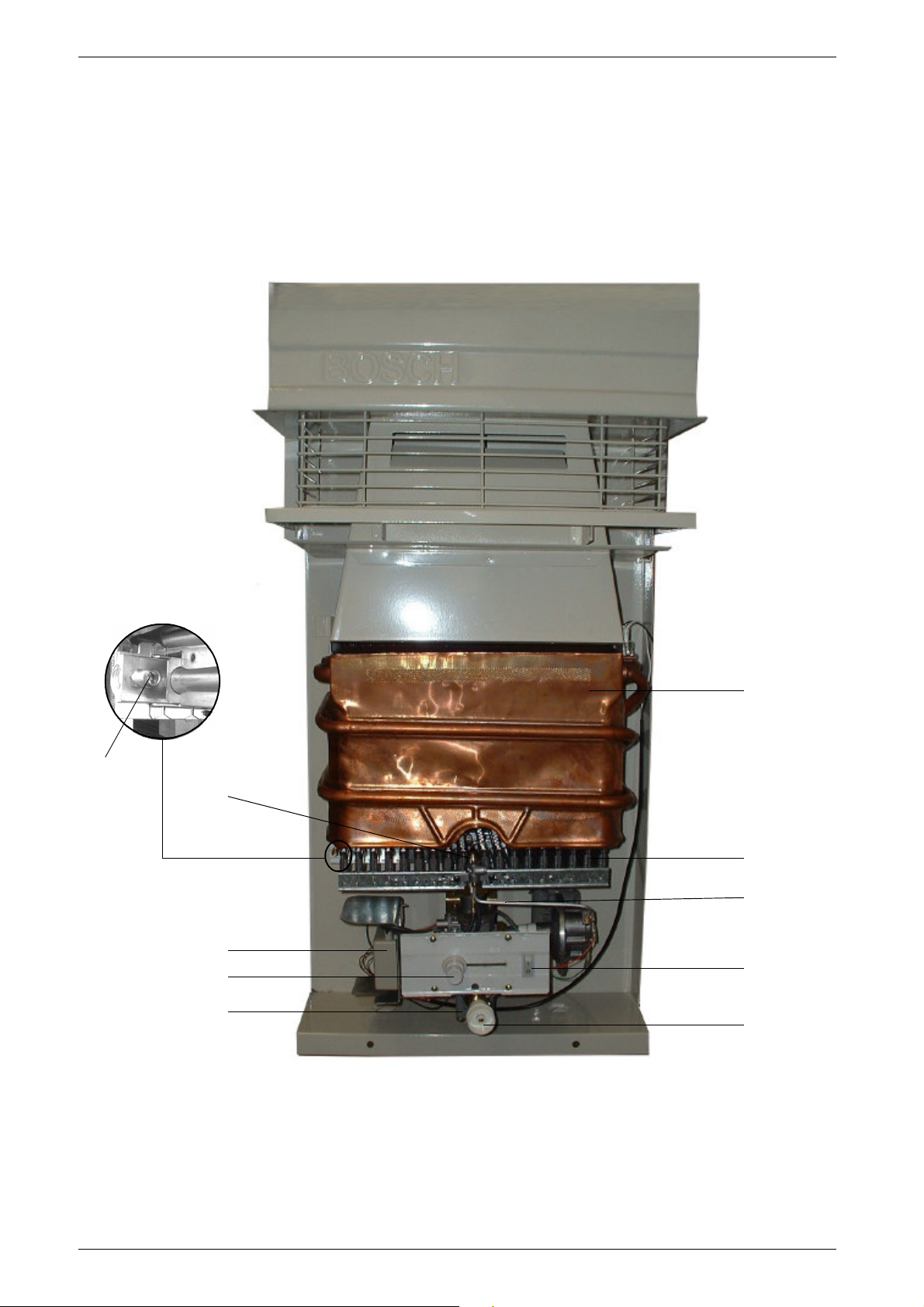
7 Interior components diagram and parts list
7.1 Interior components
Fig. 13 Functional scheme
1 Heat exchanger
2 Pilot assembly
3 Burner manifold gas pressure test nipple
4 Main gas burner
5 Pilot gas tubing
6 on/off switch
7 Water valve
8 Gas control slide
9 Electronic control box
10 Temperature adjustment selector
20
8 716 473 148
Page 21
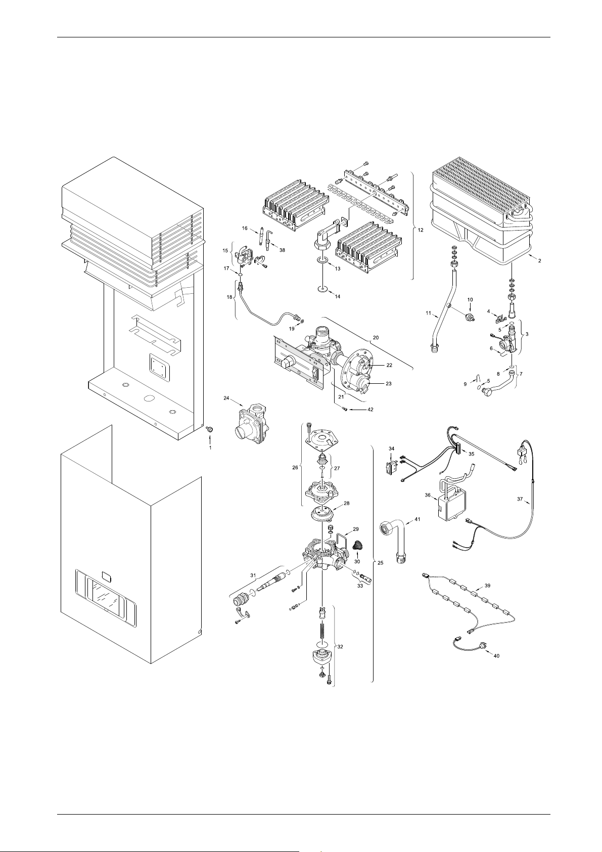
7.2 Components diagram
Interior components diagram and parts list
Fig. 14 Components Diagram
8 716 473 148
21
Page 22
Interior components diagram and parts list
7.3 Parts list
Item Description Reference
1 Screw 8 716 461 314
2 Heating body 8 705 406 235 0
3 Hydrogenerator 8 707 406 069 0
4 Wire form spring 8 701 201 020 0
5 O-ring 8 700 205 023 0
6 Wire form spring 8 704 705 030 0
7 Cold water pipe 8 700 705 947 0
8 O-ring (10x) 8 700 205 133 0
9 Wire form spring 8 704 705 025 0
10 Temperature limit 8 707 206 017 0
11 Hot water pipe 8 716 416 714
12 Burner 8 708 120 298 0 (NG)
12 Burner 8 708 120 296 0 (LP)
13 Washer 1" 8 710 103 060 0
14 Throttle disc (7,0) 8 700 100 174 0 (LP)
15 Pilot burner (41.2) 8 708 105 491 0 (LP)
15 Pilot burner (41.1) 8 718 105 051 0 (NG)
16 Flame sensor 8 708 107 007 0
17 Pilot injector (13) 8 708 200 069 0 (NG)
17 Pilot injector (74) 8 708 200 312 0 (LP)
18 Pilot gas pipe 8 700 707 370 0
19 Washer 8 700 103 173 0
20 Gas valve 8 707 021 109 0 (NG)
20 Gas valve 8 707 021 108 0 (LP)
21 Diaphragm switch 8 708 504 021 0 (NG)
21 Diaphragm switch 8 708 504 049 0 (LP)
22 Pilot valve 8 708 501 249 0
23 Servovalve 8 708 501 250 0
24 Gas regulator 8 716 487 043 (LP)
24 Gas regulator 8 716 487 044 (NG)
25 Water valve 8 707 002 708 0
26 Water valve cover 8 705 500 101 0
27 Sleeve 8 700 306 114 0
28 Diaphragm (C) 8 700 503 053 0
29 Wire form spring 8 704 705 024 0
30 Inlet water filter 8 700 507 001 0
31 Selector Screw 8 708 500 289 0
32 Volumetric water governor 8 705 705 027 0
33 Venturi (23s) 8 708 205 279 0
34 Switch 8 707 200 014 0
35 Set of cables 8 704 404 050 0
36 Ignition unit 8 707 207 078 0
37 Connecting cable 8 704 401 222 0
38 Piezo electrode 8 708 107 006 0
39 Anti frost device 8 716 459 336
40 Thermostat 8 716 459 273
41 Cold water pipe 8 716 416 715
42 Screw 8 703 401 051 0
Table 5
22
8 716 473 148
Page 23

8 Protecting the environment
Packing
The packing box may be fully recycled as confirmed by
the recycling symbol .
Components
Many parts in the heater can be fully recycled in the end
of the product life. Contact your city authorities for
information about the disposal of recyclable products.
Saving water resources:
B Make sure you close all the taps after any use. Avoid
leaving the taps dripping. Repair any leaking tap.
B Define the temperature you want. This way you have
the precise water flow needed (mixing cold water to
regulate temperature will increase the water flow with
consequent waste of water).
Protecting the environment
For increased safety shut off the appliance from
the main water supply if your are staying away
from home for a considerable time.
At below freezing temperatures, disconnect the
plumbing connections to the heater and allow
the heater to drain.
To prevent any freeze damage, introduce short
bursts of compressed air (20-40 psi) through
these connections to remove the residual water
in the horizontal pipes and water valve.
8 716 473 148
23
Page 24

Fifteen Year Limited Warranty
i
9 Fifteen Year Limited Warranty
General
BOSCH PRO water heaters are warranted by the
Manufacturer (BOSCH) through BBT North America.
BBT North America (BBTNA) will furnish a replacement
heat exchanger and will furnish a replacement of any
other part which fails in normal use and service within
the applicable periods specified below, in accordance
with the terms of this warranty. The BBTNA
replacement will be warranted for the unexpired portion
of the original warranty. This warranty will be valid only
for water heaters in possession of the original purchaser
as recorded on the warranty card.
The Heat Exchanger
If the heat exchanger fails within fifteen (15) years after
the original installation and operation, BBTNA will
furnish a replacement heat exchanger. However, if the
water heater is installed in other than a single family
dwelling, this heat exchanger warranty is limited to two
(2) years from date of original installation and operation.
Exceptions
This warranty will not apply:
• 1. to defects or malfunctions resulting from failure to
properly install, operate or maintain the unit in
accordance with the printed instructions provided;
• 2. to damage or abuse, accident, neglect or freezing
and other acts of nature;
• 3. to damage resulting from operation with either the
flame sensor rod or overheat sensor removed;
• 4. to failure of the heat exchanger resulting from the
operation of the water heater in a corrosive
atmosphere or at water temperatures exceeding the
maximum rating, or if the water heater is not supplied
with potable water;
• 5. to defects or damage cause by any attachment
or modification, including any energy-saving device.
All Other Parts
If any other part fails within three (3) years after original
installation and operation, BBTNA will furnish a
replacement part free of charge.
Shipping costs
In addition to supplying the replacement part(s),
BBTNA will provide ground service delivery for these
parts. Expedited or upgraded shipping will be charged
to the customer.
of the original water heater or a replaced water heater.
Certain service labor allowances are available to PHCC
member contractors, dependent on prior authorization
by BBTNA.
NOTE: the water heater must be free of
damaging scale deposits and not subject
to gas pressures greater than those
shown on the rating plate, which must not
be altered, defaced or removed.
How to Make a Claim
Any claim for warranty parts should be made by the
original installer or service person to the local dealer,
distributor or to BBTNA. If BBTNA, please contact the
Technical Support Department:
BBT NORTH AMERICA
Bosch Group
340 Mad River Park
Waitsfield, VT 05673
Phone 866-330-2730
www.boschpro.com
In most cases, the dealer or distributor will be able to
promptly honor your claim and subsequently notify
BBTNA. However, all replacements are made subject to
validation by BBTNA of in-warranty coverage. The
damaged or defective item must be made available in
exchange for the replacement.
Miscellaneous
No one is authorized to make any other warranties on
behalf of BBTNA. It is expressly understood that the
replacement warranty of BBTNA shall be in lieu of any
and all other warranties, express or implied, including
warranties of merchantability or fitness for a particular
use or purpose, and further that BBTNA shall not be
liable for any loss or damage directly or indirectly arising
from the use of the hot water heater, or for any
consequential damages arising from such use
(including damages from water leakage). BBTNA sole
liability with respect to any defect shall be for the
replacement of the defective part(s). Some states do
not allow such limitations and exclusions, so the above
may not apply to you.
This warranty gives specific legal rights. You may also
have other rights which vary from state to state.
Service Labor Costs
This warranty does not cover any labor costs
associated with service, removal or re-installation of
part(s). All such costs must be borne by the Purchaser.
Additionally, this warranty does not cover any labor
costs associated with service, removal or re-installation
24
8 716 473 148
Page 25

8 716 473 148
25
Page 26

26
8 716 473 148
Page 27

8 716 473 148
27
Page 28

Installer Checklist, to be performed by installer upon installation
Serial Number ___ ___ ___ ___ ___ ___ ___ ___
(8 digit serial number is located on rating plate on right side panel)
Gas Pressure Reading* Static__________ Operating__________
Building Water Pressure __________ Range if on Well system __________
Average Winter Temperature __________
Average Summer Temperature __________
Installing Company _____________________________________________
Installer name _____________________________________________
Address _____________________________________________
Phone _____________________________________________
* See Chapter 3.6 and gas pressure table (to be filled out by installer)
Installation manual should be left with the owner after the installation is tested and completed
Replacement Parts available from:
BBT NORTH AMERICA
Bosch Group
Bosch Water Heating
340 Mad River Park
Waitsfield, VT 05673
VULCANO Termodomésticos S.A.
Estrada de Cacia
3801 - 856 Aveiro - PORTUGAL
Phone 866-330-2730
Fax (802) 426-6924
www.boschpro.com
[email protected]
Recycled paper © 2005 BBT NORTH AMERICA,
Waitsfield, VT all rights reserved
 Loading...