

PRO SWEDE EL RFDA-11B, RFDEL-71B, RFDA-71B, RFDAC-71B Instruction Manual
Dimming actuator
Universal dimming actuator
RFDA-11B
RFDA-71B
RFDEL-71B
4170,4171
Warning!
Instruction manual is designated for mounting and also for user of the device. It is always a part of its packing. Installation and connection can be carried out only by a person with adequate professional qualication upon understanding this instruction manual and
functions of the device, and while observing all valid regulations. Trouble-free function of the device also depends on transportation, storing and handling. In case you notice any sign of damage, deformation, malfunction or missing part, do not install this device and
return it to its seller. It is necessary to treat this product and its parts as electronic waste after its lifetime is terminated. Before starting installation, make sure that all wires, connected parts or terminals are de-energized. While mounting and servicing observe safety
regulations, norms, directives and professional, and export regulations for working with electrical devices. Do not touch parts of the device that are energized – life threat. Due to transmissivity of RF signal, observe correct location of RF components in a building
where the installation is taking place. RF Control is designated only for mounting in interiors. Devices are not designated for installation into exteriors and humid spaces. The must not be installed into metal switchboards and into plastic switchboards with metal
door – transmissivity of RF signal is then impossible, do not use in areas aected by high-frequency interference. RF Control is not recommended for pulleys etc. – radiofrequency signal can be shielded by an obstruction, interfered, battery of the transceiver can get
at etc. and thus disable remote control.
Analogue actuator
RFDAC-71B
4280
0-10V
1-10V
02-001 Rev.6
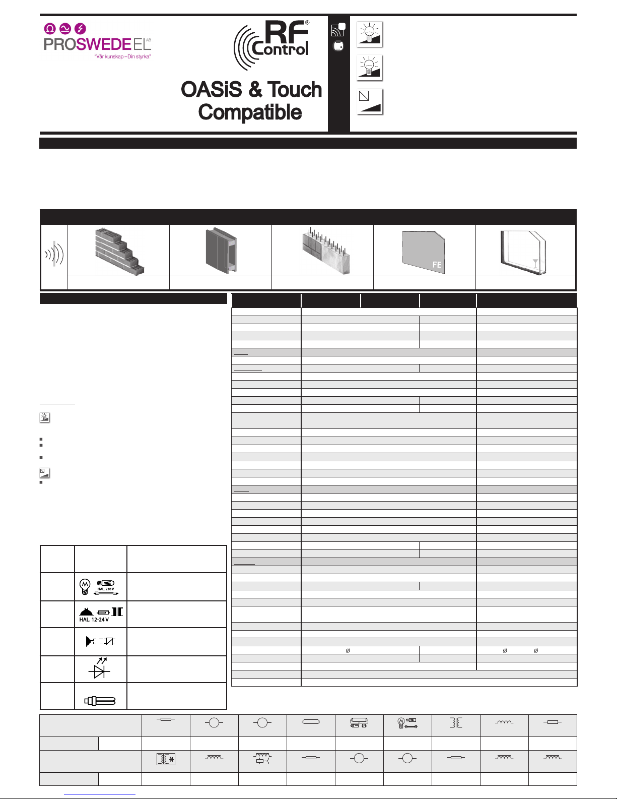
Transmission of radiofrequency signals in various materials
60 - 90 % 80 - 95 % 20 - 60 % 0 - 10 % 80 - 90 %
CA. 60-90 %
CA. 80-95 %
CA. 20-60 %
CA. 60-90 %
CA. 80-95 %
CA. 20-60 %
CA. 0-10 %
CA. 70-90 %
CA. 60-90 %
CA. 80-95 %
CA. 20-60 %
CA. 0-10 %
CA. 70-90 %
CA. 60-90 %
CA. 80-95 %
CA. 20-60 %
CA. 0-10 %
CA. 70-90 %
CA. 60-90 %
CA. 80-95 %
CA. 20-60 %
CA. 0-10 %
CA. 70-90 %
Characteristics
The Oasis & Touch compatible uses wireless communication between transmitters RF Touch and RF Pilot
(wall-mounted controller, keyring, motion detectors, door openers, etc.) and receivers to control home
appliances, lighting, electrical equipment, garage gates and roll-up shutters.
It enables you to switch various devices on and o depending on the time of start or your return. It allows
controlling and setting various lighting scenes, sunrise or sunset simulations, as well as controlling roll-up
shutters, screens and canopies. Using sensors, the RF Control system warns you of any motion of persons
or re in your home.
It is ideal for installation into existing buildings, new constructions as well as refurbished houses, without
any need to chisel into the wall. Receivers (actuators) may be installed directly into a suitable mounting
box or lighting covers.
- The RF Control system operates at 868 MHz.
- All transmitters are compatible with each other and can be combined with the previous version of the RF
Control system.
Warning: Actuators without the OASIS & Touch Compatible designation are not compatible with RF Touch
or RF Pilot units.
Transmitter designs:
Dimming actuator
- is used for creating lighting scenes, controlling light or a group of lights.
RFDA-11B: basic - 1 light scene , OFF function .
RFDA-71B: multifunction - 7 program functions: 6 dierent light
functions, ON/OFF function
RFDEL-71B: Multifunction unit- 7 programmable functions: 6 light function, ON / OFF function
select the type of load, setting of min. brightness
0-10V
1-10V
Actuator with analogue output 0(1)-10V
RFDAC-71B: for continuous regulation of devices controlled with
continuous voltage 0(1) - 10V.
- 7 program functions: 6 dierent light functions, ON/OFF function.
- output voltage mode 0-10V or 1-10V selected by pressing the Prog
button. Buttons > 2s. After releasing the button, the LED ashes,
indicating the output mode:
- the green LED -0-10V
- the red LED - 1-10V
All other signalling is indicated by the relevant colour LED.
- mounting box design (such as KU-68).
Power
supply
symbol description
R
resistive
Classic or halogen bulb
L
inductive
Coil transformer for low voltage halogen
bulbs
C
capacitive
Electronic transformer for low voltage
halogen bulbs
LED
dimmable LED 230 V
ESL/ КЛЛ
Dimmable energy saving lamps
Type of load
cos φ ≥ 0.95
M M
HAL.230V
Type of load
K
M M
RFDAC-71B
RFDAC-71B
AC12
250V / 1A
x
AC1
250V / 16A
AC2
250V / 5A
AC3
250V / 3A
AC5a uncompensated
230V / 3A (690V)
AC5b
1000W
AC6a
x
AC7b
250V / 3A
AC5a compensated
230V / 3A (690VA) do
max C=14uF
mat. contacts
contact
AgSnO
2
16A
AgSnO
2
16A
DC14
x
AC13
x
AC14
250V / 6A
AC15
250V / 6A
DC1
24V / 10A
DC5
24V / 2A
DC12
24V / 6A
DC13
24V / 2A
DC3
24V / 3A
mat. contacts
contact
* loadability of power factor cos φ=1
Power factor of dimmable LED and ESL bulbs moves in following range: cos φ = 0.95 to 0.4.
Aproximate value of maximal load is achieved by multiplication of loadability of dimmer and power factor connected to a light source.
Technical parameters
RFDA-11B RFDA-71B RFDEL-71B RFDAC-71B
Suply voltage:
Apparent input:
Loss input:
Supply voltage tolerance:
Connection:
Output
Contactless:
Load capacity
Resistive load:
Capacitive load:
Inductive load:
LED
ESL
Zero-potential analogous output/
max. current:
The choi ce of output vo ltage:
Relay contact:
Rated current:
Switching power:
Switching voltage:
Mechanical life:
Electrical life (AC1):
Control
By RF command by transmitter:
Range in op en area:
Min. programming distance:
Minimum control distance:
Button:
- Prog.:
- external:
Neon:
Other data
Operation indication:
Supply indication:
Operating temperature:
Storage temperature:
Operating position:
Mounting:
Protection degree:
Overvoltage category:
Pollution degree:
Output leads :
Length of leads:
Dimensions:
Weight:
Applicable standards:
EN 60669, EN 300220 , EN 301489; směrnice/directive RTTE, NVč. 426/2000Sb (směrnice/directive 1999/ES)
8.3 VA / cos φ = 0.1
0.83W
+10 % / -15 %
3-vodičové, s “NULOU“ / 3-wired, with “NEUTRAL“
250 W*
x
x
x
x
-15.. +50 °C
3 x 0.75 mm
2
90 mm
230 V AC /50Hz
2 x MOSFET
x
x
x
x
x
x
x
x
868 MHz
až 160 m
20 mm
20 mm
tlačítko / button PROG (ON/OFF)
červená / red LED
x
-30 až +70°C
libovolná / any
volné na přívodních vodičích /
loose on connecting wires
IP 30
III.
2
49 x 49 x 21 mm
40 g
1.1 VA
0.8 W
+10/ -15 %
4-vodičové, s “NULOU“
160 W*
Ano
Ne
-20 až + 35 °C
4 x 0.75 mm
2
90 mm
110 - 230V AC / 50-60Hz
3 VA
1.2 W
+10% / -15%
5-vodič ové, s “NULOU“/ 5-wired, with “NEUTRAL“
x
x
x
x
x
x
x
0 (1) -10V DC/ 10mA
0-10V DC, 1-10V DC
1xAgS nO2, spíná fá zový vodič / switch. ph ase wire
16 A / AC1
4000 VA / AC1
250 V AC1
3 x 10
7
0.7 x 10⁵
868 MHz
až / up to 200m
20 mm
20 mm
tlačítko/button PROG (ON/OFF)
x
x
červeno-zelená/red-green LED
x
-15 .. +50 °C
-30 až +70°C
libovolná / any
volné na přívodních vodičích /
loose on connecting wires
IP 30
III.
2
3x 0.75mm2, 2x 2.5 mm
2
90 mm
49 x 49 x 21mm
52 g
Industrigatan 4
212 14 Malmö
Sweden
- LED ashs 2x in each 1s interval
- press programmable button on receiver
PROG
- press exact control element
- by RF KEY and RFWB-40/G is rst control position
set just by one touch of control element, second
control position is set automatically
- press any control element (rst next press after 1s)
- t setting
- LED on receiver is ashing in 1s interval
Legend
Delete all
3 x 3 x
PROG
> 8s1 x
Programming mode
1s - max. 4min.1 x
PROG
> 1s1 x
Deleting one transceiver
1s
PROG
> 5s1 x
Timing mode /
PROG
> 5s1 x
0.5s1 x
Manual control
PROG
< 1s1 x
Delete all
3 x 3 x
PROG
> 8s1 x
Programming mode
1s - max. 4min.1 x
PROG
3s 1 x
Deleting one transceiver
1s
PROG
> 5s1 x
Manual control
PROG
< 1s1 x
Change the input mode
PROG
1s 1 x
Timing mode /
PROG
> 5s1 x
0.5s1 x
Operation modes of receivers
RFDA-11B; RFDA-71B; RFDEL-71B
RFDAC-71B
Control RFDEL-71B
RFDEL-71B
Control with connected button:
- Short button push (<0.5s) turns on / o the light
- Long button push (> 0.5s) enables continuous control of light intensity.
- external button is superior to commands of the the RF units (RFTouch, RF Pilot RF Key), RF signal is blocked for 5 seconds after
release of
external buttons
Dimmer control:
- If the light is off, short push (<0.5s will switch on the light to the stored brightness level
- Long push continuously regulate the light intensity. The brightness level is stored after button release
- Minimal brightness setting is for setting of minimal brightness and suppression of spontaneous blinking or switching off
- For ESLbulbs, short button press increase increase brightness to a maximum level (to „spark“ on the gas discharge in ESL)
and then drops to the preset brightness level
Set the minimum brightness:
- Minimum brightness setting turned on when we perform load by turning the potentiometer min. brightness to the desired value.
- Min. brightness is automatically stored after cca. 3 seconds since the last potentiometer position change.
Setting the load type:
- Setti ng the type of l oad is perf ormed with di sconecte d load by turni ng the light sou rce selecto r to the desire d position
Description of device protection
RFDEL devi ce is protec ted against ove rheating, sh ort-term and l ong-term over load:
Error s are signaled by r apidly ashi ng STATUS LED on the fron t panel of RFDEL
- Thermal protection: activate d at constant o utput overlo ad or insuci ent cooling of t he device.
Prot ection is ac tive until th e dimmer cool do wn to the worki ng temperatu re. Then you can t urn on the dimm er again.
Remo ve the fault by pr oviding a bet ter cooling of t he dimmer, reduc ing the input o f the connec ted load, or swi tching to
cor rect posit ion of the light s ource
- Short-term overload: activates by a large short-term overload, such as short-term short-circuiting.
The pr otection is si gnalised by a sho rt ashing of t he connecte d load. Remove th e fault by reduc ing amount of co nnected
load,
or by s witching to th e correct po sition of the li ght source
- Long-term overload: activated b y permanent sh ort circui t, output over load or exces sive amount of co nnected lo ad.
The pr otection d evice turns o after 5 minut es and dimmer tr ies to switc h on again. Remove t he fault by red ucing amount
of connected
load a nd check of the w iring by quali ed elect rician
Additional Information:
Do not mix mo re types of l ight sources!
Do not tr y to use energy s aving bulbs th at are not label ed as dimmable!
Incorre ct setti ng of the type o f light source a ects the e xtent and di mming (but no dam age to the dimme r or load)
Incorre ct setti ng of the type o f load can caus e overheatin g of dimmer
Maximum number of light sources depends on their internal structure
List of te sted light sou rces see Table. on w ww.rfcon trol.cz in / da ta / svetelne_ zdroje_ RFDSC.pdf
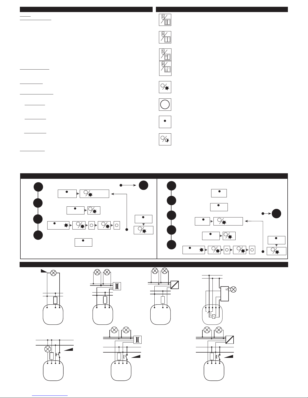
coil transformer electronic transformer
controlling of power dimmers
V L N
RF DA C-71 B
T
L
N
N
L
1-10V
T
L
N
L
N
V L N S
LED, ESL, R
RFDEL-71B
R L C
R
L
N
RF DA-11B
RFD A-71B
N L V
L
L
N
RF DA-11B
RFD A-71B
N L V
C
L
N
RF DA-11B
RFD A-71B
N L V
L
N
V L N S
L
RFDEL-71B
L
N
V L N S
C
RFDEL-71B
Connection
 Loading...