

Page 1
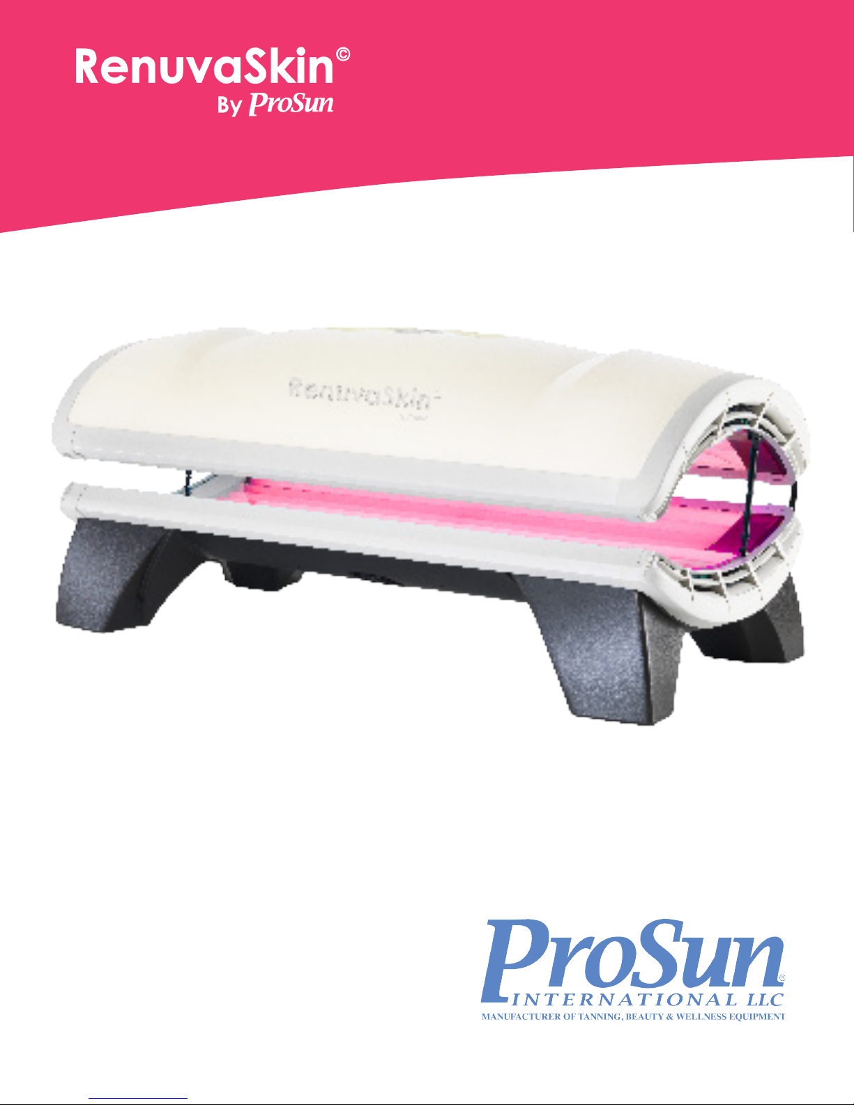
User's Manual 15 Minutes
RenuvaSkin JD 3200 by ProSun
15 MINUTES
ProSun International, LLC
2442 23rd Street North
St Petersburg, FL 33713
www.ProSun.com
800-874-2776
E304-031
Page 2

Table of Contents
CONGRATULATIONS on your ProSun® purchase!
Your new unit has been manufactured with the utmost care and attention and consists of
high-quality parts. We are very proud of our products and it is very important for us that we deliver
quality products. That’s why every unit runs a full cycle in our Quality Control Department.
Please make sure you read this manual carefully before using this equipment and specifically the
maintenance schedule. ProSun has drawn up a maintenance schedule to ensure good performance
and maximum life of your unit. It is strongly recommended to adhere to these service instructions and
intervals. Always disconnect the power before starting any maintenance work or cleaning!!
In the event there are any issues/problems, please contact ProSun at 727-825-0400
Important Customer Information ……...................…..................................3
Warning/Danger Label ……………………………….……………...............…3
Lamps ……………………….…..….……................................…...…........…. 4
Exposure Recommendation .........................................................................4
Electrical Requirement……..………..…………………..........................….....5
General Notes……………………………………………….…..………........….6
Assembly .…………………………………………………...............................8
Assembly Introduction ................................................................................8
Included Parts .............................................................................................9
Assembly ......................................……………………….............................10
AddingT-Max ............................................................................................. 18
Integrate T-Max ......................................................................................... 20
Operation ...................................................................................................24
Care and Maintenance .………………………………………….....................28
Preventative Maintenance ……………………………………………….…....30
Replacement of Components …………………………….…........................31
Warranty ………………………………………………………………..............32
Page 3
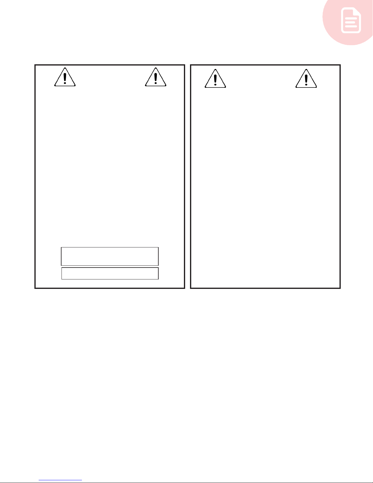
Warning/Danger Label
WARNING
• Read the instruction booklet before using this
product
• When using a folding combination machine with a
canopy and bench, lie down on the bench and pull
the canopy down as far as it will go.
• When using a canopy only, lie down and pull the
canopy down to a point no closer to the body then
the minimum allowed usage distance 4 inches or
10 centimeters
• Operation of this device closer to the body than
the recommended minimum distance for use may
result in overexposure
• Recommended eye wear; provided eye shields
(Intrexco nr. 5635/1s) or equivalent eyewear as
dened under 21CFR1040.20.2(b)(6)
• Two pair of protective eye wear are furnished with
this equipment and should be worn all persons in
the room when lamps are on
• Disconnect power before attempting to clean,
replamp, or engage in the maintenance of this
product
CAUTION DISCONNECT
UNIT BEFORE SERVICING
DANGER
• Follow instructions
• WEAR PROTECTIVE EYEWEAR -FAILURE TO DO
SO MAY RESULT IN SEVERE BURNS OR LONG
TERM INJURY TO THE EYES
• Medications or cosmetics may increase your
sensitivity to light
• To reach maximum session times, follow the
recommended exposure schedule
Complies with CFR 1040.20
3
Page 4
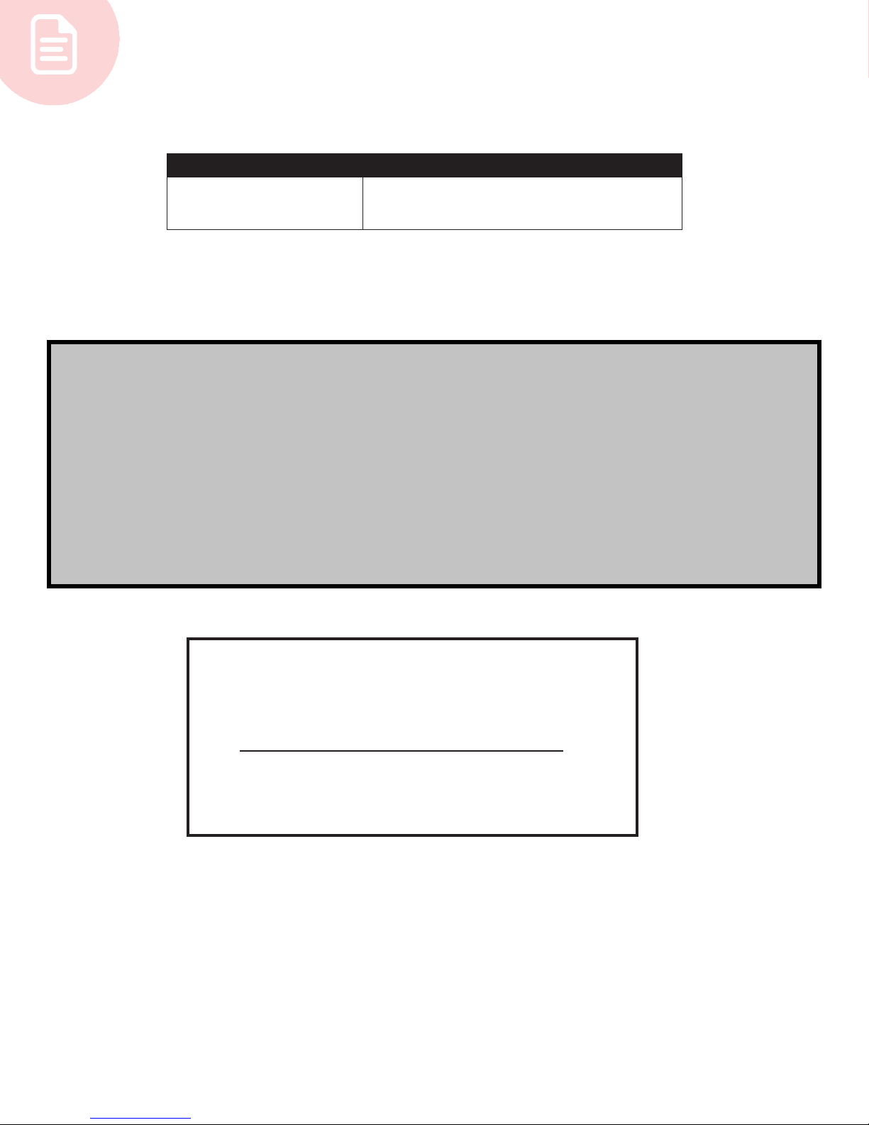
Lamps
Model Lamp
RenuvaSkin JD 3200
Canopy: RenuvaSkin 18 x 75" 110W
Bench: RenuvaSkin 14 x 71" 100W
Exposure Recomendation
Session Times
• For optimum results use this product for a minimum period of 10-15 weeks. (Results may
vary)
• Sessions should be conducted every other day for no longer than the recommended 15 minute session time.
• To maintain results, continue using this product 1 time a week for the recommended 15
minute session.
Note: We recommend you write down your serial number in the manual to have it on hand
for any future part orders or service needs.
4
Serial Number
Page 5
Electrical Requirements
Important Notice:
• Never operate this machine when the ambient room air temperature is greater than 90
degree fahrenheit
• Never operate this machine in a commercial application when t he remote timer is not
working properly.
• Never operate this machine when it is not ventilating itself properly (too hot inside).
• The salon owner or operator may never, under any circumstances, open the bench or
canopy of tanning units without the supervision of an authorized service person.
CAUTION: Please refer to your individual unit for the recommended exposure schedule and
proper exposure times for the model that you have purchased.
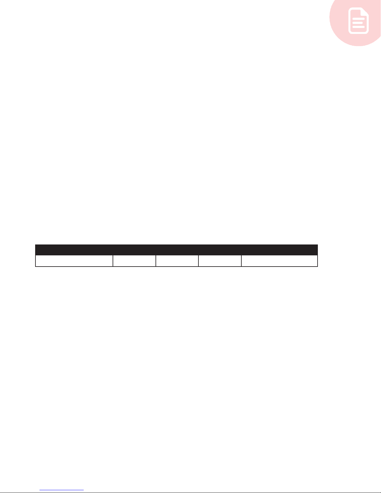
The Electrical requirements for your ProSun unit are:
Model Breaker Volt Hertz Operating Amps 1
RenuvaSkin JD 3200 20 Amp 120V 60 Hz 19 Amps
Operating any 220 Volt combination at voltage levels below 215 Volts or above 230 Volts
for the ProSun Units constitutes an automatic NULLIFICATION of the manufacturers factory
warranty, because it could cause damage to the unit’s system.
Please insure that your electrician and/or installer, reads this user’s manual carefully prior to
the installation of your ProSun unit. You will need a buck booster if voltage requirements are
not met.
WARNING: Always disconnect the ProSun unit from its power supply when serving or
repairing the unit.
5
Page 6

General Notes
• Every eort has been made to ensure that the equipment outlined reects the actual
equipment expected to be installed. The equipment is positioned in such a manner as to
provide optimum operation. The customer shall bear the sole responsibility for compliance
with all applicable codes, OSHA, NEMA, local and national standards.
• Expressed or implied on the part of ProSun®, its dealers, distributors or other designated
agents, shall be contingent upon strict compliance with electrical, structural, and
mechanical recommendations contained in this manual unless specied otherwise in the
equipment sales order.
• The customer is responsible for all room preparation, costs, fees, permits, and inspections
unless specied otherwise in the general order for equipment purchased.
• ProSun®, its dealers, distributors or designated agents shall supply all interconnecting
cables required for the equipment installation and setup. Additional power, grounding or
ancillary equipment shall be the responsibility of the customer unless specied otherwise
in the equipment sales order.
• Equipment installation cannot begin until the room is complete and ready for equipment
installation. To include; contractors equipment, electrical requirements and room
construction.
• ProSun®, its dealers, distributors or designated agents shall reserve the right to refuse to
install and equipment into any room which has not been properly prepared in accordance
with these general notes.
• All electrical work shall conform to the requirements of the national electrical code, OHSA
or applicable local and or state ordinances, as well as, utility company rules regarding
ampere interruption and safety shunt trip switches and power panels of which shall bear
the label of underwriter's laboratories, incorporated and shall be permanently marked for
easy identication.
• All wires shall be single solid runs without splices meeting the NEMA standards
• The electrical contractor shall provide and install all electrical material as specied for a
safe operating system.
• The electrical contractor shall provide and install all electrical material as specied for a
safe operating system.
• The electrical shall ring out, tag, and terminate all wires at both ends, with each run to be
inspected to ensure that no wires have been grounded or are open.
• The customer shall provide a dedicated power source when called for by ProSun®, its
dealers, distributors or other designated agents.
• ProSun®, its dealers, distributors or other designated agents are not responsible for
the nal installation of the electrical system. The recommended electrical plan must be
coordinated between the customer and the electrical contractor. Any deviation of the
electrical plan before, during, and after equipment installation is the responsibility of the
customer.
• The electrical contractor shall ensure the completion of all electrical requirements prior or
the installation of any ProSun® system.
6
Page 7
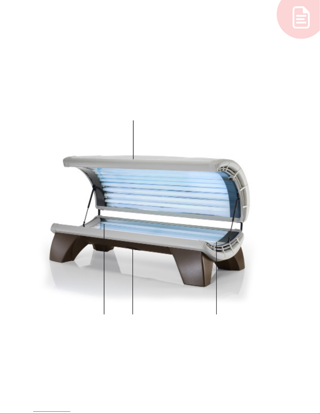
* Unit can only be used by one(1) person during a session
* Remain laying down during session, with face towards facials
Canopy
Feet Bench
Head
7
Page 8
Assembly Introduction
Required for assembly (not included):
• 1 wrench to tighten bolts
• Power adapter kit (220V for commercial use, for warranty to apply voltage must be
between 218-230 V)
*Make sure to write the Serial Number (located on the back of the canopy) down on the
previous page and store the manual somewhere you can easily access. The Serial Number is
MANDATORY to order parts for your unit, as well as, any customer service calls.
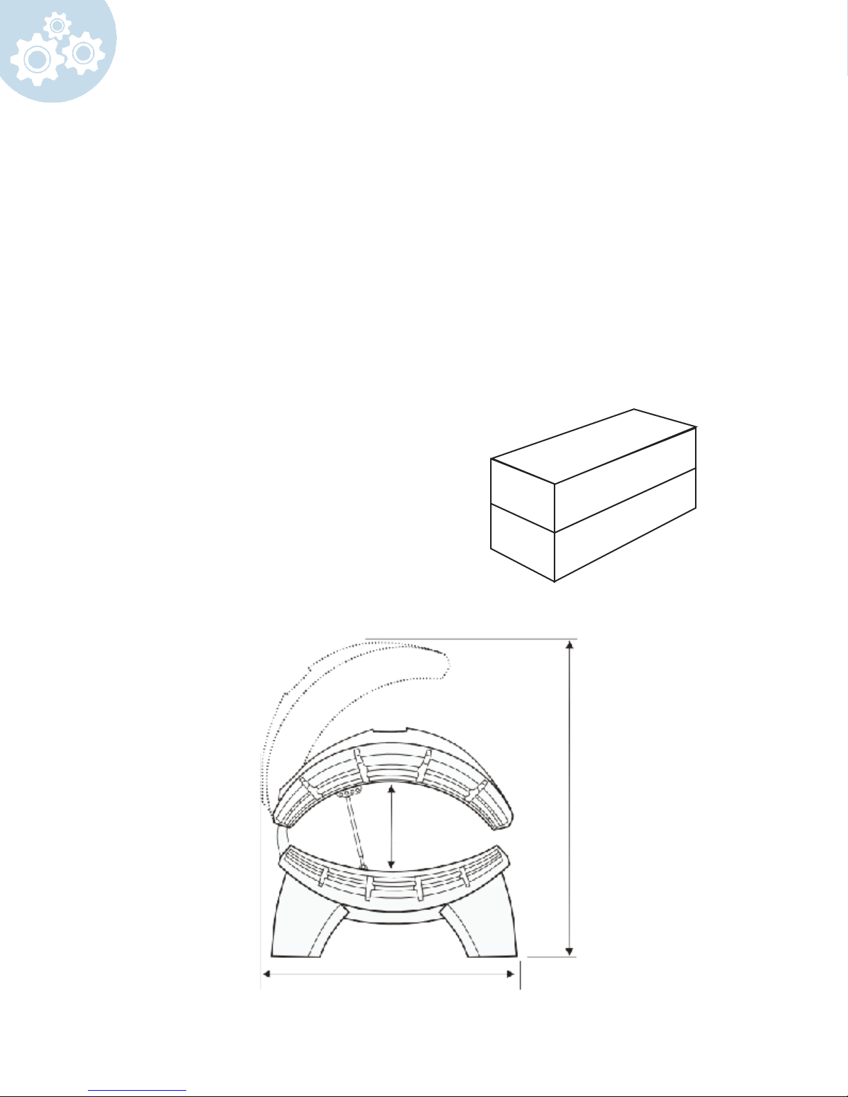
The boxes should be shipped in this manner.
Bench
14"
Canopy
47"
Side view
8
35"
L = 83"
Page 9
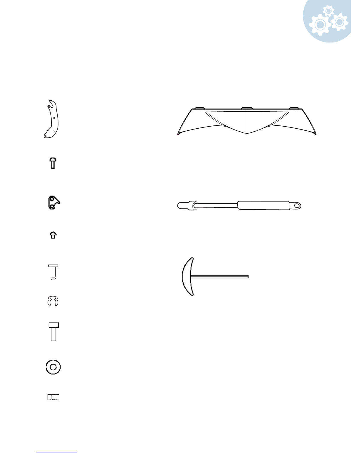
2 Combi Arms
FAMS6012171
Included Parts
Make sure all parts are included before you begin.
6 Combi Arm Screws
FASN1508828
2 Security Plates
FAMS6012236
4 Security Plate Screws
FASN1513151
4 Gas Shock Pivots
GASP9008435
4 Security Clips
GASP90008436
2 Deco Shield Screws (optional)
black
FASN5010879
1 Plastic Front Skirt (optional)
bronze - CVPL 6012336
red - CVPL 6513606
white - CVPL 6525156
1 Gas Shock
1 Alan Wrench
ACCE1009552
2 Deco Shield Washers
FASN6001362
2 Deco Shield Nuts
FASN3001132
9
Page 10
Assembly
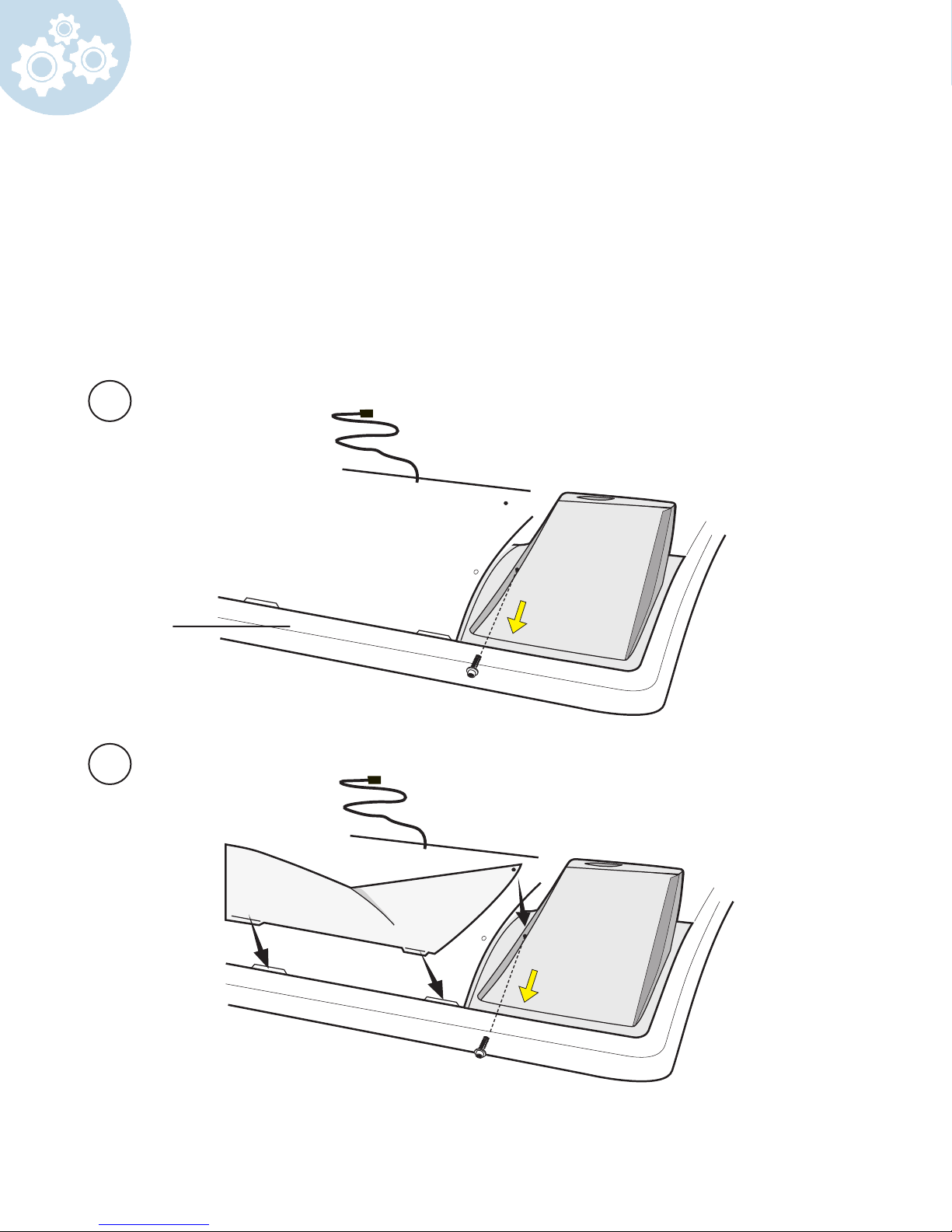
Carefully remove the bench from box and keep it face down.
*Optional Front Skirt (if you do not have a plastic front skirt go to step 3)
Retrieve
1 Plastic front skirt (located in canopy box)
Remove the screw from the leg.
1
2
bench
Insert plastic front skirt and screw in place. Repeat these steps on other side.
10
Page 11
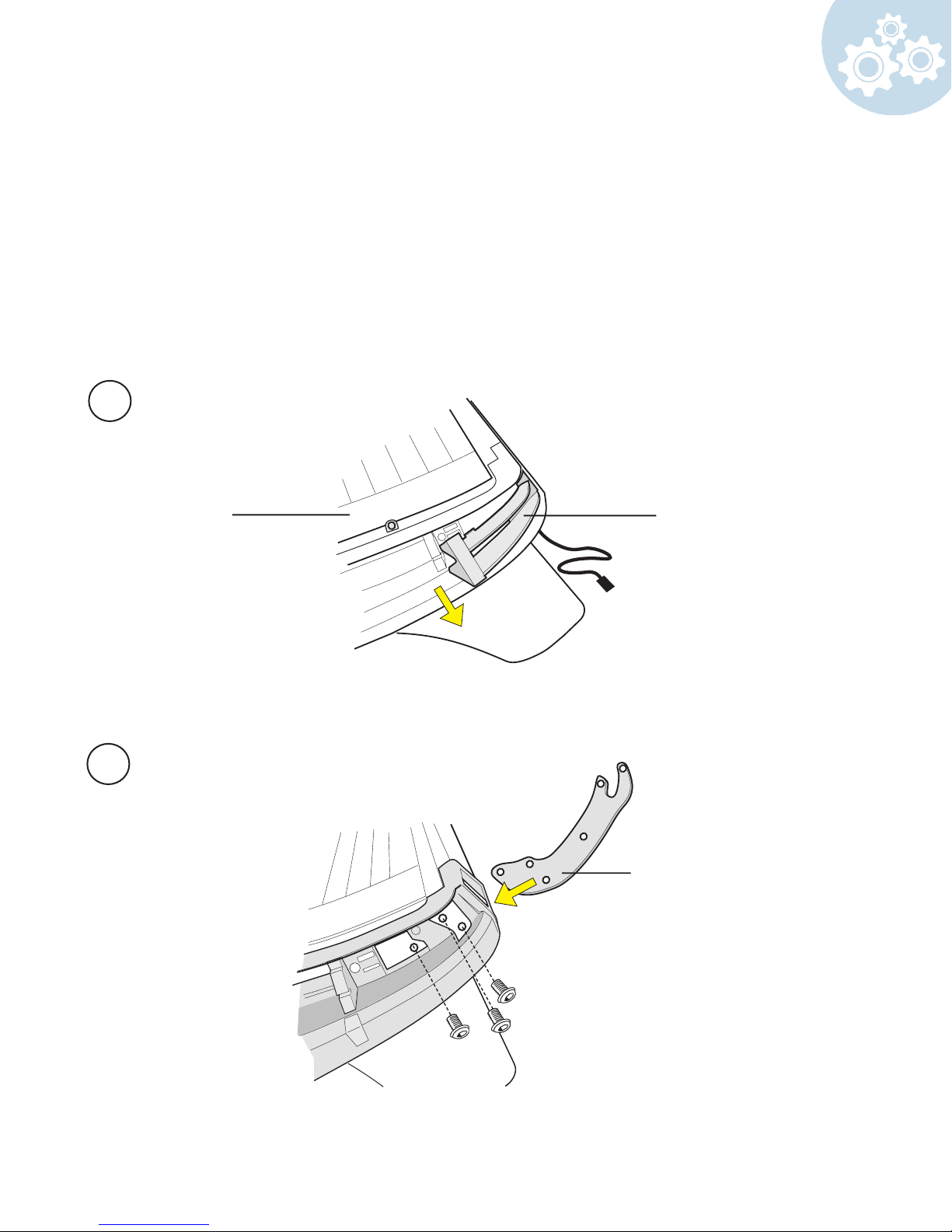
Flip bench over.
Retrieve
2 Combi Arms
6 Combi Arm Screws
Remove the end cap ller.
3
end cap llerbench
4
Insert combi arm into bench and secure with screws. Repeat these steps on other side.
1
combi arm
11
Page 12
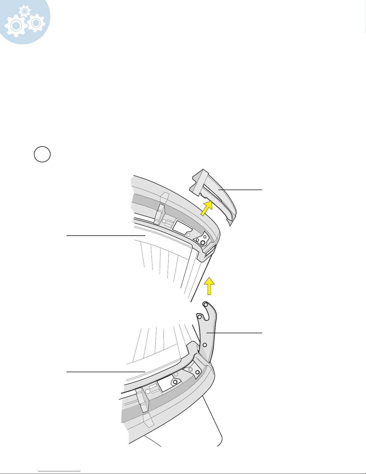
Remove the canopy from the box.
Remove the end cap ller as done previously with the bench.
While holding the canopy on each end attach it to the bench by sliding it onto the combi arms
5
end cap
ller
canopy
1
bench
12
2
combi arm
Page 13
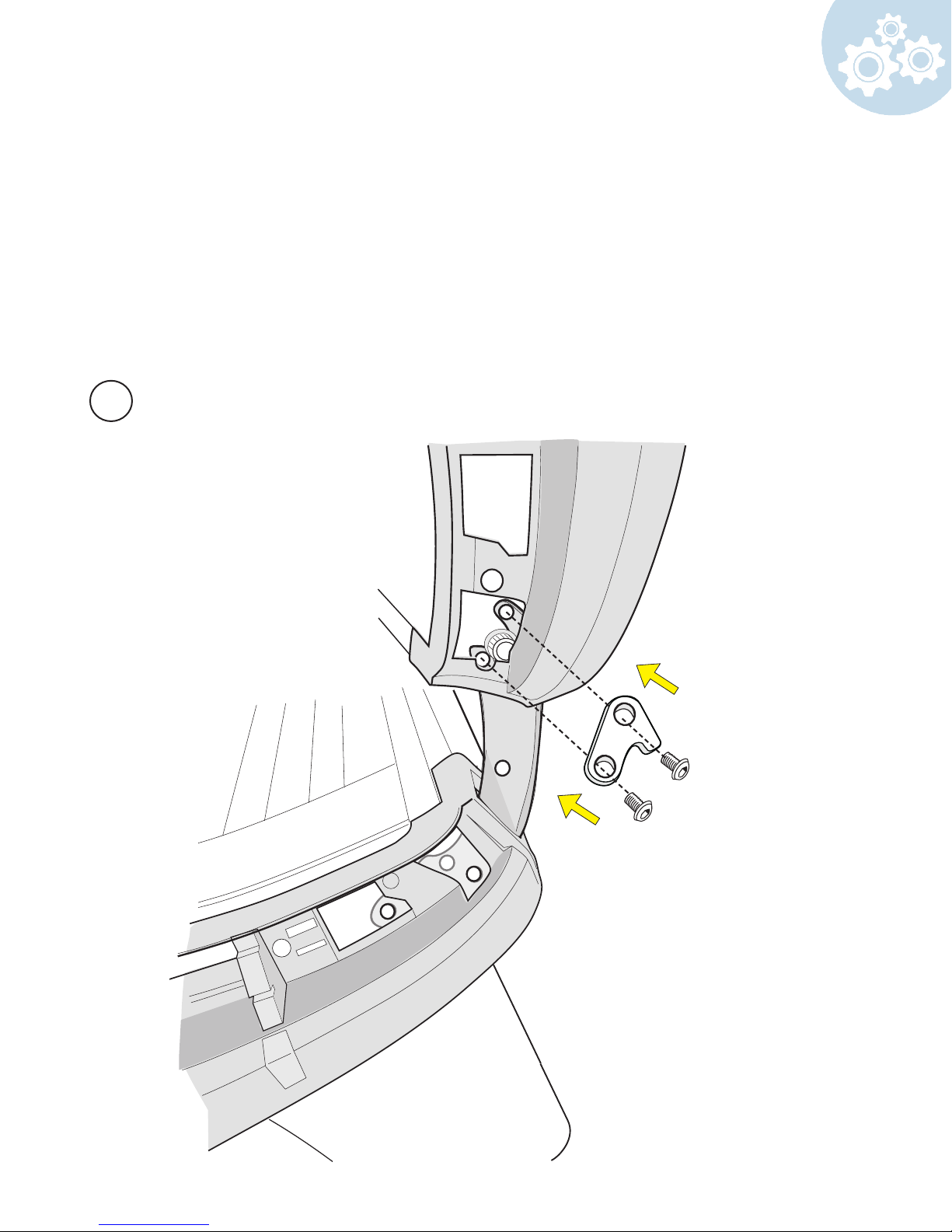
Retrieve
2 security plates
4 security plate screws
Once the canopy is attached to the bench, secure the security plate into place with security
plate screws.
Repeat these steps on other side.
6
13
Page 14
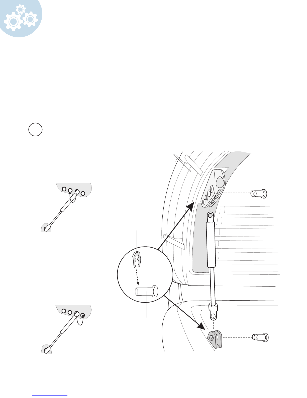
Retrieve
2 Gas shocks
4 Gas shock pivots
4 security clips
While the canopy is in an open position, insert gas shock into the bench and into third hole on
the canopy. Then insert gas shock pivots and secure with a security clip.
7
If the canopy rises
spontaneously move gas
shock to hole 2
1
If the canopy lowers
spontaneously move gas
shock to hole 4
Security clip
2
Gas shock pivot
14
Page 15
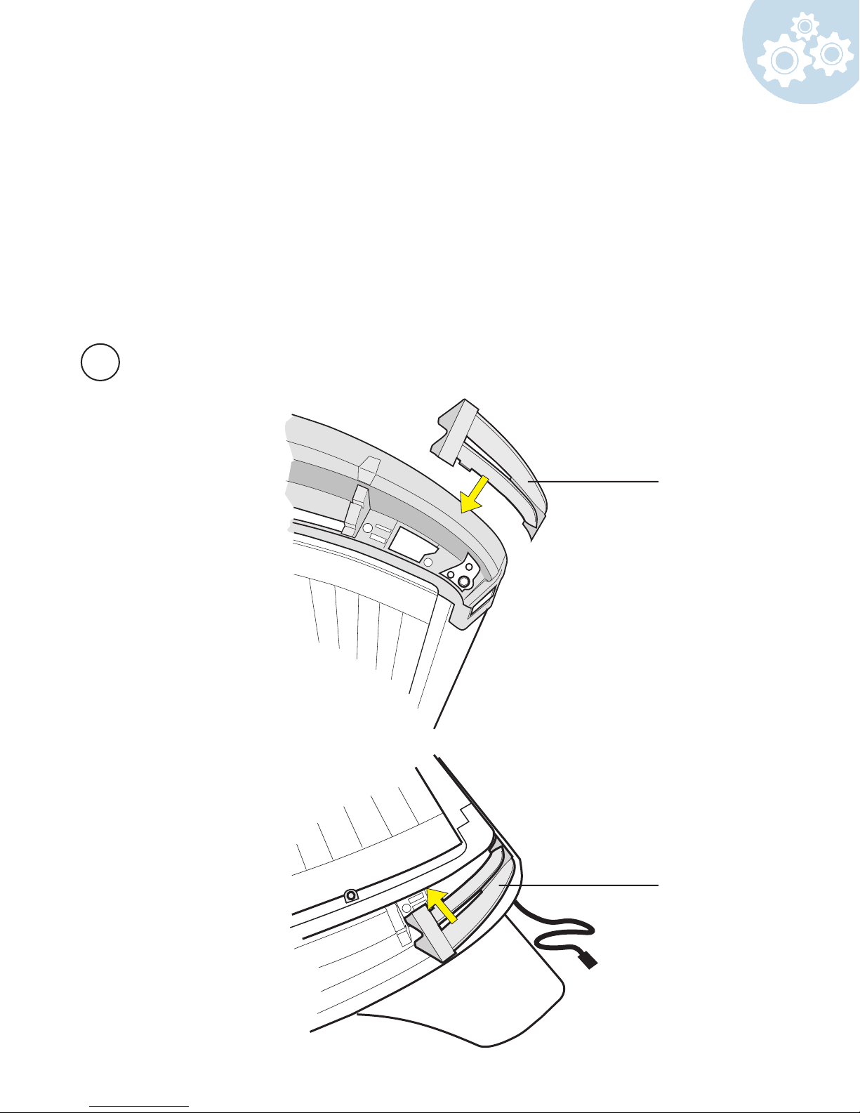
The four end cap llers that were removed need to be inserted back into the bench
and canopy.
8
End cap
ller
End cap
ller
15
Page 16
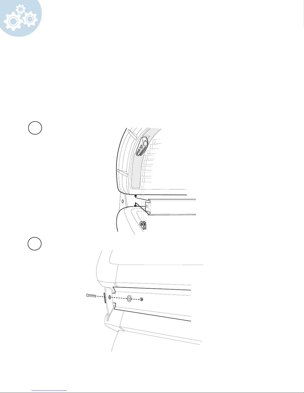
*Optional Deco Shield
Retrieve
1 Deco shield
2 deco shield screws
2 deco shield washers
2 deco shield nuts
Insert the deco shield in between the canopy and bench.
7
8
screw
Secure by attaching the decor shield to combi arm.
16
washer
nut
Page 17
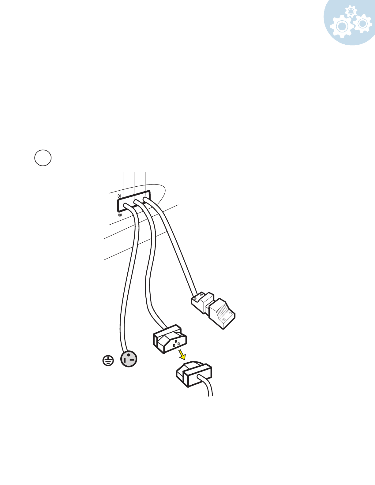
On the back of the canopy you will see three chords:
Plug "A" into your wall outlet (or into optional buck booster)
Plug "B" in the bench
"C" is used for the T-Max timer which is an optional additional feature (if you do not have a
T-Max then the chord will remain unused)
9
A
B C
Used for optional t-max
timer, see next page for
directions
220 volt 30 Amp plug
17
Page 18
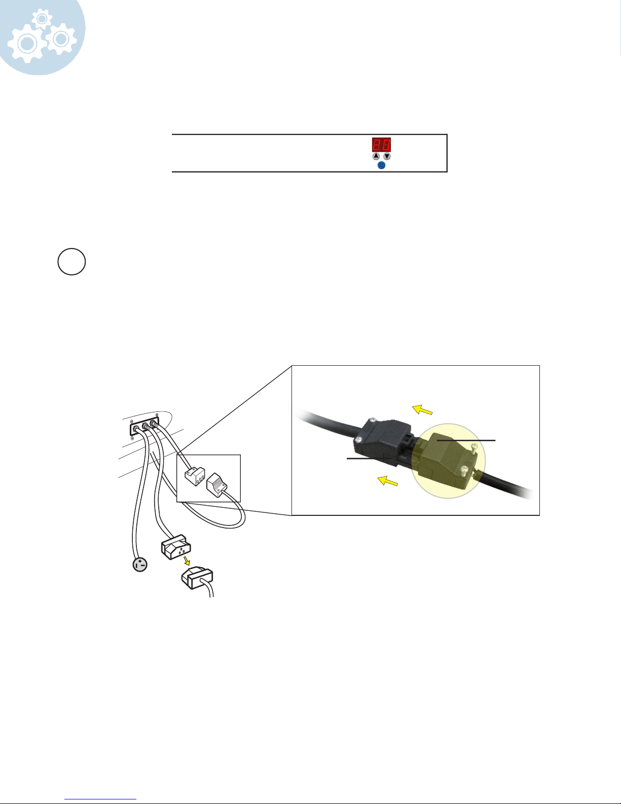
Optional T-Max Connection
If the deco shield has an integrated t-max system follow the steps below.
* For commercial use only
Plug the male end (located on the back of deco shield) into the female end (located on the
back of canopy)
1
Back of
canopy
Male
Female
18
Page 19
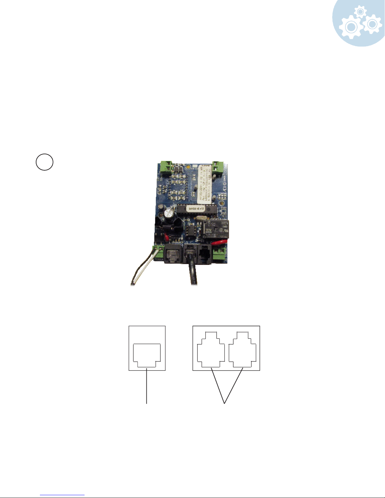
If necessary unscrew the backing of the t-max timer to expose the 3 data ports.
Connect the corresponding cables.
2
wireless adaption
Daisy ChainConnection for
19
Page 20
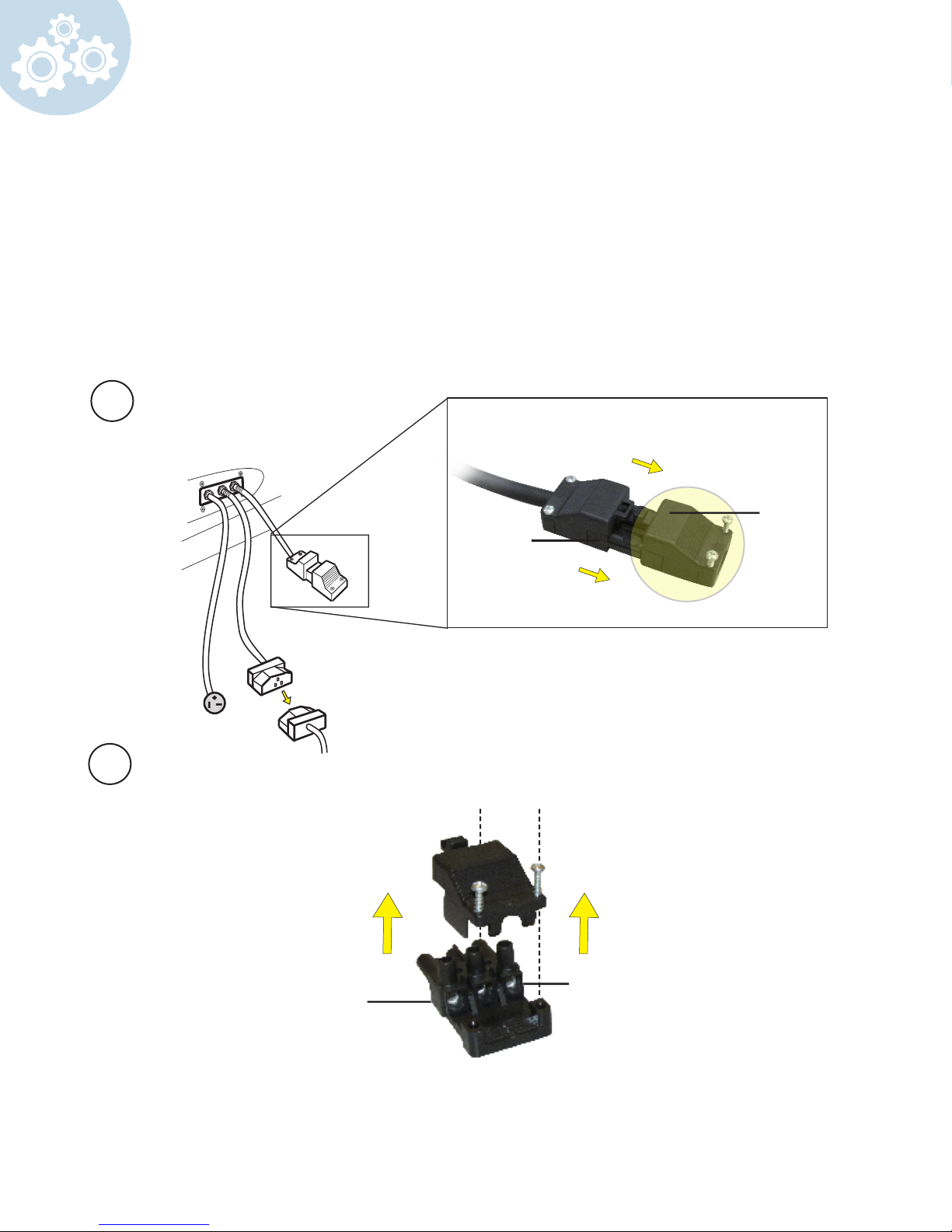
Optional T-Max Connection
If you are adding a T-Max timer to your unit follow the steps below.
* For commercial use only
Remove the male end from the female (located on the back of the canopy)
1
Back of
canopy
Female
Male
2
Pin 1
neutral
Unscrew and remove top.
20
Pin 3
live
Page 21
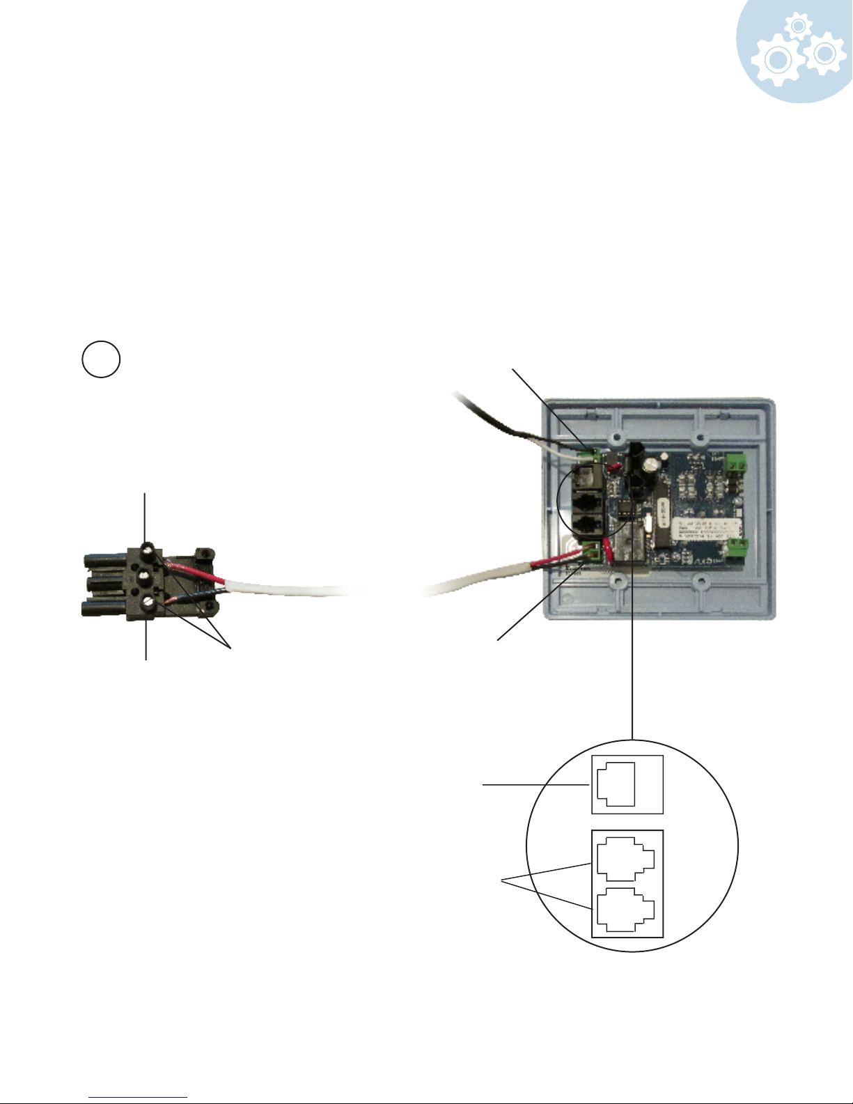
You will need an 18/2 speaker cable.
Insert one end of the 18/2 cable into the J3 Contact on the back of the T-Max. Insert the other
end into Pins 1 and 3 on the male part. Tighten screws to hold cables in place.
**Make sure that the 18-2 cable is long enough to reach from the bed to the location of the
T-Max timing display.
3
Pin 3
live
Pin 1
neutral
Tighten screws once
cables are inserted
Power 9-12 V
J3 Contact
Wireless
adaption
connection
Daisy Chain
21
Page 22
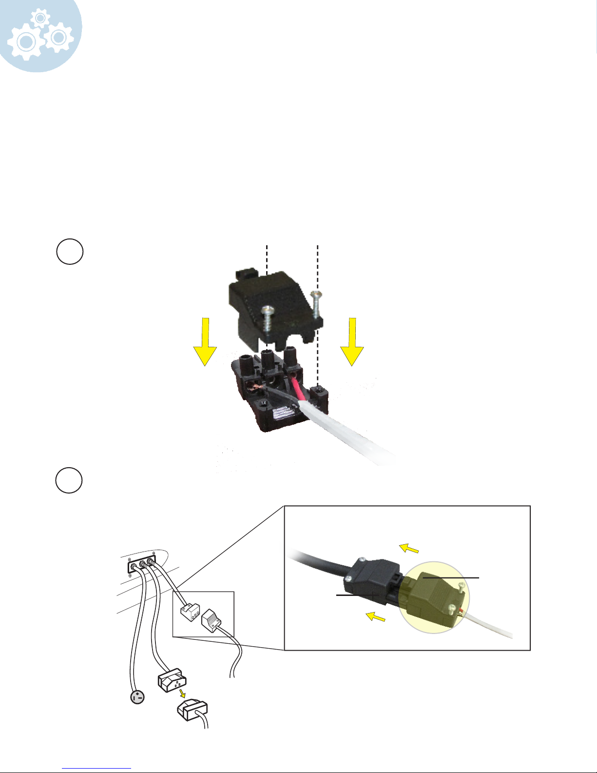
After all the appropriate cables connected, screw the top back on.
4
5
Back of
canopy
22
Male
Female
Page 23
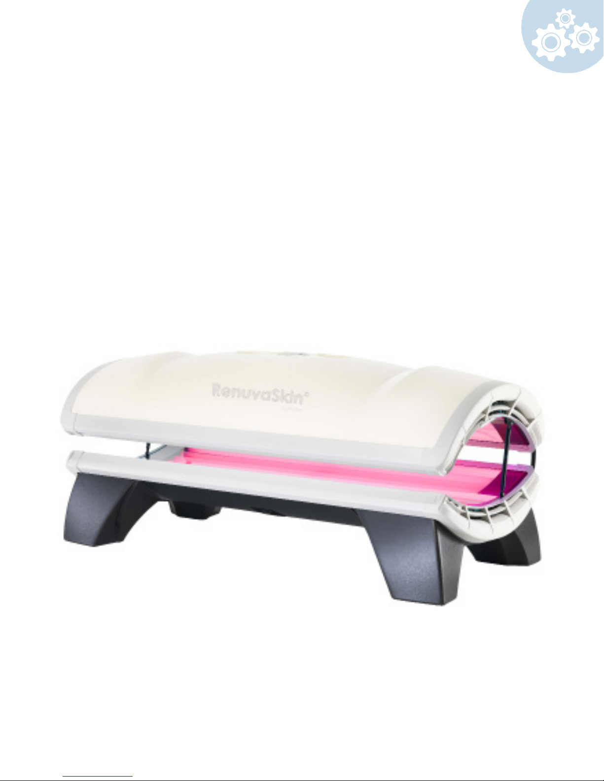
Congratulations! Your RenuvaSkin JD 3200 is now ready for use.
Refer to the operation instructions on the next page to use your new red light
unit.
23
Page 24
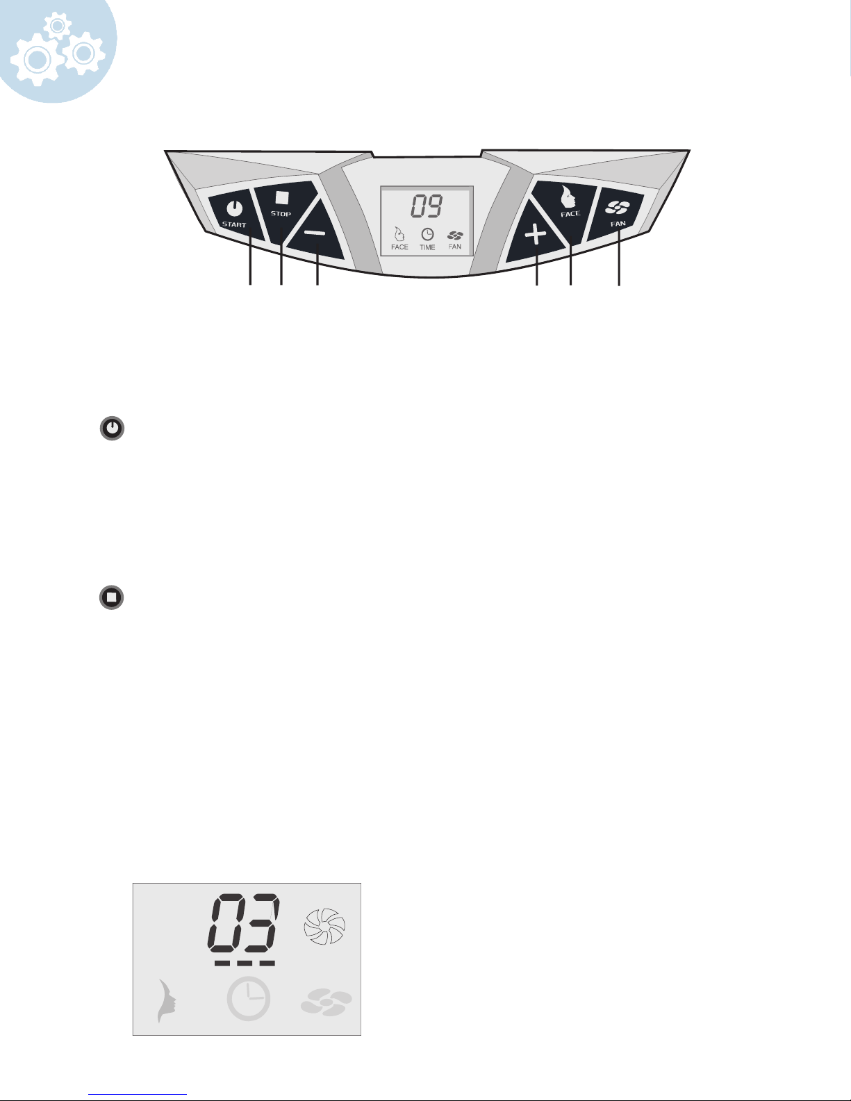
Operation
A B C D E F
Note: Typically Stand-alone mode is for residential use and Remote mode is for commercial use
All units come standard in remote-mode
A
B
Start
Stand-alone mode:
By depressing start once the “+ and –“ buttons can be used to set the session time.
Pressing for a second time will start the unit.
Remote mode: (only for commercial units)
The unit can be started automatically by the external timer. The start button can be
used only when the unit has to be restarted from “pause”.
Stop
Stand-alone mode: (for residential units)
Pressing stop once will cause the unit to “pause”. The lights will go out but the
ventilation will continue
to run.
Pressing stop twice will initiate a mandatory after-cooling phase of 3 minutes. The unit
cannot be started during these 3 minutes.
Remote mode: (only for commercial units)
Pressing stop once will cause the unit to “pause”. The lights will go out but the
ventilation will continue
to run.
The unit will not respond to pressing stop several times. The external timer
automatically will switch the unit o. Switching o will initiate a mandatory cool down of
3 minutes. The unit cannot be started during these 3 minutes.
24
Illustration after-cooling
Page 25
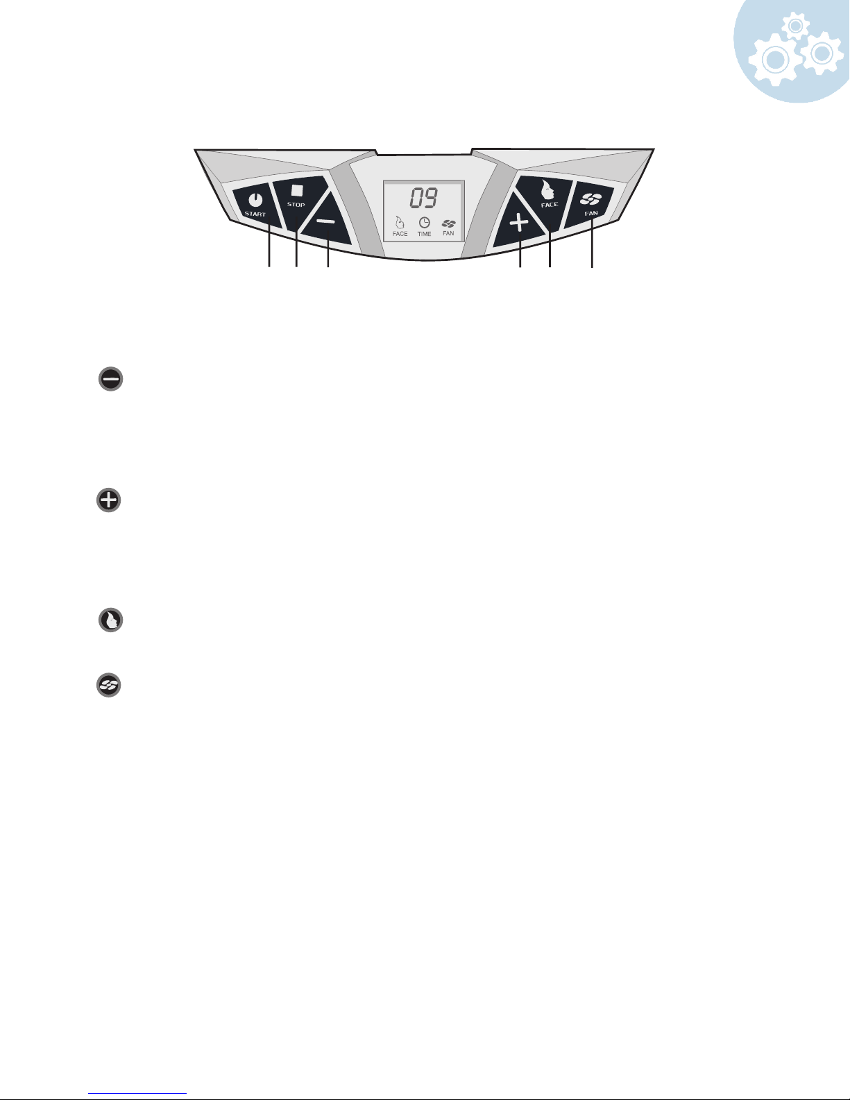
A B C D E F
Stand-alone mode:
a. Reduce session time
b. Reduce body cooler speed
Coin mode:
a. Reduce body cooler speed
Stand-alone mode:
a. Increase session time
b. Increase body cooler speed
Coin mode:
a. Increase body cooler speed
Face
Switch the facial light on and o
Fan
Switch the body cooler on and o
25
Page 26
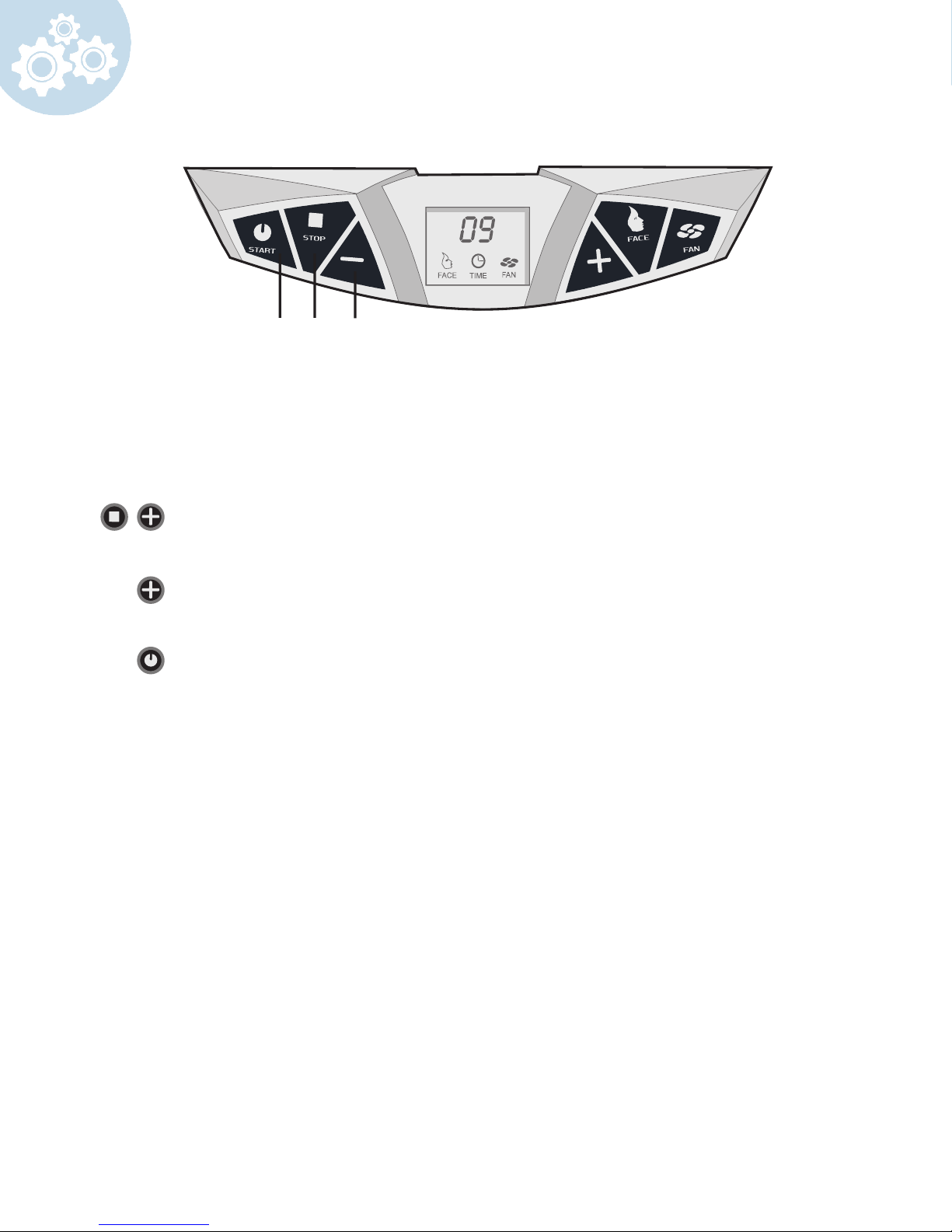
A B C D E F
General:
The unit is generally set for use with external timer. When the unit has to operate in
combination with an remote timer (remote mode), the internal time should be set to 0
minutes. If you want to use the unit in stand-alone mode follow the steps below:
Press both "stop" and "+" and hold for 10 seconds until "01" is shown.
Press the "+" button and continue to press until the display indicates “15”
Press start once and the unit will beep in response.
Note: The maximum session is restricted to 15 minutes.
Press start again and unit will show "15" min.
Press start for a third time and unit will turn on.
26
Page 27
A B C D E F
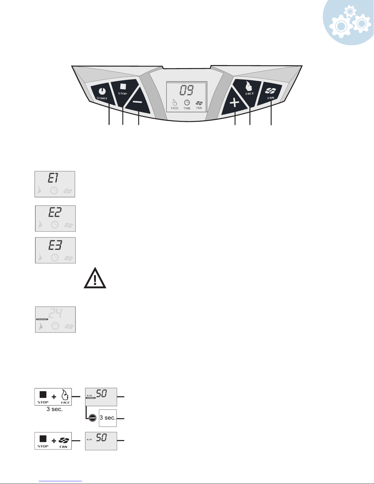
Display messages:
Overrule error (Switch print and/or display print defective)
Filter glass defect (Filter glass of the face tanner is broken or glass protection
is defective) or unit is overheated
Communication error (No communication between switch print and display
print)
Note: When you receive one of the above error messages on your
LCD display, you should stop using the unit and unplug it. Please
contact your dealer.
This symbol will appear on the LCD display after 500 lamp hours. It is
preferable after 800 lamp hours to replace the lamps with new ones. After
replacing the lamps reset the lamp hour counter.
Note: The exposure label on the front of the unit shows the lamps that are
suitable for your unit.
Reading Hour Counter:
Hour counter lamps x 10
Reset hour counter lamps
Hour counter red light bed x10 (not able to reset)
27
Page 28

Care and Maintenance
The Care and Maintenance in this section covers most of the diculties that you may
encounter under normal working circumstances. If your tanning bed fails to operate properly,
please review the following steps before calling for service.
THE BED YOU PURCHASED CONTAINS VOLTAGES WHICH ARE POTENTIALLY
HAZARDOUS. ALL REPAIRS AND GENERAL MAINTENANCE SHOULD BE
PERFORMED BY QUALIFIED SERVICE PERSONNEL.
FOR YOUR RED LIGHT BED:
Safe and continuous operation of your bed depends partially on the care taken by users.
Please observe the following precautions when bed is in use.
• Do not disassemble any part of the bed while in use.
• Do not allow sharp objects in the bed while in use.
• Do not allow liquid or any foreign objects to get inside the bed.
• Ensure the beds back side is at least 8 – 12 inches away from the wall.
• Avoid having the acrylic sheets come in contact with sharp edges and objects.
• The room or cabin in which the unit is operated must be well ventilated.
• Make sure that the unit never comes in contact with water while connected to power.
• Do not turn the machine on and o frequently within the space of 3 minutes.
• When replacing or cleaning Facial Lamps, both facial lenses and bulbs should be cleaned
with alcohol, keeping them free of smudges and nger prints.
28
Page 29
Care and Maintenance
Cleaning the machine
Always disconnect the main power from the unit before attempting to clean or repair it.
Dust the lamps with a dry cloth - do not use cleaning uid or alcohol. The acrylics should be
taken out at least once every week of operation and cleaned thoroughly with a non-alcoholic
disinfectant glass or surface cleaner. If alcohol is used, the acrylic may fade, crack, or break
altogether. Failure to use anything other than an approved cleaning material on the acrylic
will result in poor red light transmission, and could eventually cause injury to the person using
the machine. Use a vacuum cleaner with a dust nozzle to clean around the ballast racks and
throughout the interior portions of the base, top deck, and bench.
Longevity of the acrylic sheets
The acrylic sheets used in this machine should be changed between 1200 and 1500 hours
of operation. If not, transmission could be greatly reduced. ProSun® recommends the use of
Lucasol or Solacryl when cleaning acrylic sheets
Longevity of the lamps
Lamp lifespan is about 1,000 hours.
IMPORTANT: When replacing or cleaning Facial Lamps, both facial lenses and bulbs should
be cleaned with alcohol, keeping them free of smudges and nger prints
WARNING DANGER
NEVER use this unit if the lter glass is missing, cracked or otherwise damaged. SEVERE
INJURY may result within seconds.
What to do with old lamps?
Contact your local garbage disposal company or city authority to nd out what is the most
environmentally sound manner of throwing away old uorescent lamps.
For more maintenance information please visit our website at:
www.prosun.com/customer-service/equipment-care/
29
Page 30
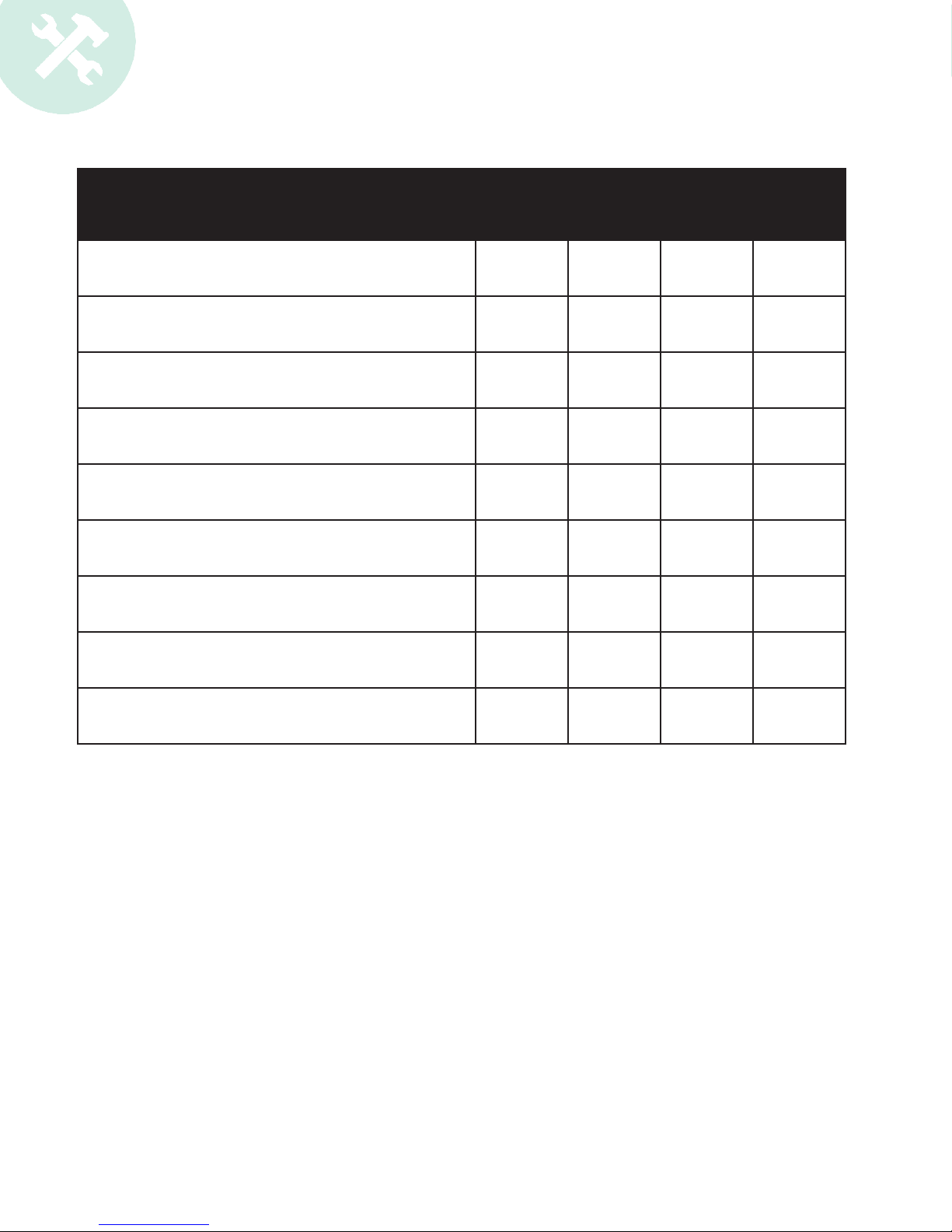
Preventative Maintenance Schedule
Frequency After
Each
Session
Click Strips are rmly in place X
Clean & Sanitize Bed Exterior X
Remove & Clean inside of acrylic sheets X
Dust Lamps X
Wipe & Vacuum fans & vents X
Clean all reectors X
Inspect Acrylics for cracks & wear X
Daily Weekly Monthly
Check hinges bolts for proper tightness X
Inspect vent hoses for optimum ventilation X
30
Page 31

Replacement of Components
WARNING: Before doing any repair or replacement work on this machine, ALWAYS
disconnect the power at the main circuit breaker(or, if the main power cable has a wall plug,
pull it out).
Lamp replacement:
Holding the lamp at both ends, turn it counter-clockwise until the bi-pins can slide easily out
of the lamp holder socket, and slowly take it out of the unit. Clicks will be heard as the socket
incrementally rotates. Replace the lamp in just the opposite manner, making sure that the
labeling on the lamp itself is pointed outward.
SEE WARNING LABEL FOR LAMP TYPES.
IMPORTANT: Only use manufacturer-authorized replacement components. Failure to do so
many void warranty.
High pressure facial lamp (400 Watt) replacement:
Remove the blue and clear lter glasses by loosening their respective securing screws on the
frame of the facial light cassette. Making absolutely sure not to touch the glass of the lamp
itself, take it out of its box and set it to the side. Hold the old lamp also by one end and push
it into the opposite end of the spring-loaded lamp holder, until the end you are holding comes
free. Replace the new lamp in just the opposite manner, but do not touch the glass of the
lamp.
SEE WARNING LABEL FOR LAMP TYPES.
IMPORTANT: Only use manufacturer- authorized replacement components. Failure to do so
may void warranty.
31
Page 32

Warranty
LIMITED WARRANTY
EFFECTIVE June 2015
1. Warranty Period: PROSUN warrants light equipment manufactured or imported by it,
provided it is still owned and operated by the original purchaser, to be free from defects in
material and workmanship under normal use and service, for a prorated period of twelve
(12) months from the date of delivery to the original Purchaser. Equipment intended for
residential use, where a Prosun authorized dealer sells equipment to a third party, will be
considered active when the third party takes possession of the equipment or six months
after the dealer takes possession of the equipment- whichever occurs rst.
2. What is covered: During the warranty period as specied above PROSUN will replace
any defective system or component, at PROSUN’s sole discretion. Prior to making any
repairs PROSUN will advise the Purchaser of the nature of the problem and the cost to
the Purchaser based on the proration of the defective system or component.
3. What is not covered:
A. Acrylic sheets, starters (igniters), lamps, blue and clear lter glass.
B. Any plastic parts aected by discoloration.
C. Cracked or broken cover plates, end caps and sidebars
D. Any failure to the external timing system (example: T-Max, FST timers and timer
system components)
E. Any failure to the external voltage transformer (example: “buck and boost”
transformers)
F. Any damage caused by the failure of any supporting hardware not supplied by
PROSUN.
G. Any labor charges, travel time charges, or mileage charges associated with a warranty
item.
H. Shipping costs back to PROSUN’S factory. PROSUN will pay for ground transportation
of repaired or replaced part back to purchaser.
I. Tanning units, parts or components damaged in transit where PROSUN’S damaged
goods policy is not followed by purchaser or purchaser’s designee.
This warranty does not apply to any failure of product due to alterations,
modications, misuse, abuse, neglect, accident, improper maintenance or
installation, use of parts not supplied by PROSUN, failure to operate and
use the product in accordance with the instructions provided in the Owner’s
Manual supplied with the product or failure to otherwise meet manufacturer’s
specications, or if the serial number has been removed, altered or defaced.
4. Procedure for Requesting Warranty Work: In the event of a problem covered under
this limited warranty, the customer must rst contact PROSUN and obtain a returned
goods authorization form for products to be repaired or replaced at PROSUN’s discretion,
provided product(s) are returned freight prepaid to PROSUN. PROSUN will perform its
obligation within thirty (30) days from the date of receipt of the authorization form and
the part(s). Electronic replacement parts purchased after the original warranty period
hold a 90-day warranty, if the parts have been purchased from PROSUN and installed
by PROSUN’s instructions and approval. Any payment due from the Purchaser shall be
payable in full prior to PROSUN’s return of the repaired or replacement part. Any product
being returned to PROSUN for repair or replacement must be adequately packaged to
prevent freight damage and shipped via traceable method.
5. Right to Modify: PROSUN reserves the right to make changes or improvements in its
products without incurring any obligations to similarly alter products which have been
previously purchased.
32
Page 33

6. Exclusivity of Warranty: This warranty is the only warranty made by PROSUN and may
only be modied or amended by a written instrument signed by a duly authorized ocer
of PROSUN. PROSUN’s sole and exclusive liability and Purchaser’s sole and exclusive
remedy under this warranty shall be, at PROSUN’s option, to repair or replace, to the
extent available on a prorated basis, any such defective Products. These remedies
are available only if PROSUN’s examination of such Products discloses to PROSUN’s
satisfaction that such defects actually exist and were not caused by Purchaser’s misuse,
abuse, neglect, improper installation, maintenance or testing, alterations or modications,
failure to meet manufacturer’s specications or any other cause beyond the range of
normal usage, or by accident, re or other hazard. Repair or replacement of a part does
not extend the warranty period or extend the prorated value of a part or product beyond
the initial two year limited warranty period from the date of delivery.
THE WARRANTY SET FORTH ABOVE IS IN LIEU OF ALL OTHER WARRANTIES,
EXPRESS OR IMPLIED, INCLUDING BUT NOT LIMITED TO ANY IMPLIED
WARRANTY OF MERCHANTABILITY OR FITNESS FOR A PARTICULAR
PURPOSE. IN NO EVENT SHALL PROSUN BE LIABLE FOR ANY INCIDENTAL OR
CONSEQUENTIAL DAMAGES WITH RESPECT TO THE PRODUCTS DELIVERED
HEREUNDER OR SUBSEQUENT USE THEREOF.
7. Limitation of Liability: PROSUN shall not be liable for any loss, damages, or penalty
resulting from failure to perform any of its obligations under this Agreement due to major
force or any cause beyond its reasonable control.
PROSUN’S LIABILITY UNDER OR FOR BREACH OF THIS AGREEMENT SHALL
NOT EXCEED THE REFUND OF THE PURCHASE PRICE LESS REASONABLE
RENTAL FOR PAST USE. IN NO EVENT SHALL PROSUN BE LIABLE FOR COSTS
OF PROCUREMENT OF SUBSTITUTE GOODS BY THE PURCHASER OR FOR
UNAUTHORIZED REPAIRS UNDERTAKEN BY THE PURCHASER WITHOUT
PROSUN’S PREVIOUS WRITTEN APPROVAL. IN NO EVENT SHALL PROSUN
BE LIABLE FOR ANY SPECIAL, CONSEQUENTIAL, OR INCIDENTAL DAMAGES,
HOWEVER CAUSED, WHETHER FOR BREACH OF WARRANTY, NEGLIGENCE, OR
OTHERWISE. PROSUN DISCLAIMS ANY OBLIGATION OR LIABILITY FOR LOSS
OF USE OF THE PRODUCT WARRANTED, LOSS OF TIME, INCONVENIENCE,
RENTAL OR SUBSTITUTE PRODUCTS, LOSS OF BUSINESS, LOSS OF INCOME,
COMMERCIAL LOSS OR ANY OTHER DIRECT, CONSEQUENTIAL, SPECIAL OR
INCIDENTAL DAMAGES.
8. Governing Law: Notwithstanding principles of conicts of law of any jurisdiction to the
contrary, all terms and provisions of this Agreement are to be construed and governed
by the laws of the state of Florida without regard to the laws of any other jurisdiction.
The Purchaser waives any and all privileges and rights which they may have under
Chapter 47, Florida Statutes (1993), relating to venue as it now exists or may hereafter
be amended, and under any other statute, or administrative provision thereof in any legal
action on this Agreement; and further, the Purchaser agrees that any legal action brought
on this Agreement or in connection therewith, shall be brought in the appropriate court in
Pinellas County, Florida.
9. Attorney’s Fees: Should a dispute arise with regard to this warranty or any other aspect
of this sale the prevailing party shall be entitled to reasonable attorneys fees and costs
through appeal.
33
Page 34

ProSun International, LLC
2442 23rd Street North
St Petersburg, FL 33713
www.ProSun.com
800-874-2776
 Loading...