

Page 1

Manual
Non-Programmable Thermostats
User
PRS3110
Single Stage Heat / Cool
Conventional and Heat Pump
PRS3210
Up to 2 Heat / 1 Cool
Conventional and Heat Pump
Model number is located on back of thermostat
1
Specifications
2
Installation
3
Setting User Options
Warning
Turn off power to the heating or cooling
equipment before installation.
Attention
For installation by experienced service
technicians only.
Read all instructions before proceeding.
This thermostat requires 24 Volt AC Power or two (2) properly installed
“AA” Alkaline batteries for proper operation. When connecting 24 Volt
AC Power the batteries may be installed as a backup.
installation and all components of the system shall conform to
Class II Circuits per NEC code.
For use only as described in this manual. Any other use will void warranty.
Operating Your Thermostat
4
5
Additional Operation Features
6
Thermostat Maintenance
Thermostat
Specifications
1
PRS3210
only)
Single compressor heat pump systems with an auxiliary heat stage (PRS3210)
PRS3210 – Rc, Rh, O, B, Y1, E/W1, G, W2, C
PRS3110-100-02
Page 2
Installation
2
Warning
Disconnect power before beginning installation.
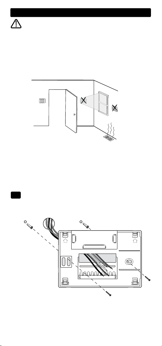
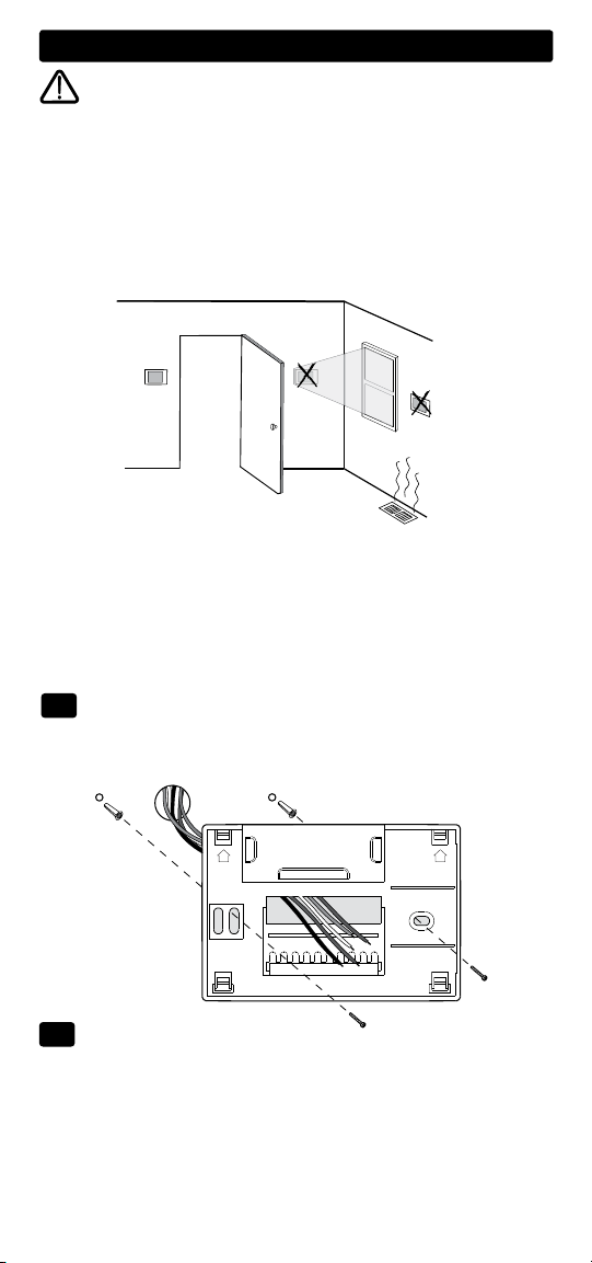
Thermostat Location
Install the thermostat approximately 5 feet (1.5m) above the floor in an
area that has a good amount of air circulation and maintains an average
room temperature.
Avoid installation in locations where the thermostat can be affected by
drafts, dead air spots, hot or cold air ducts, sunlight, appliances, concealed
pipes, chimneys and outside walls.
Install your new PROSTAT thermostat in 5 basic steps:
1 Install the Sub-Base
2 Provide Power
3 Connect Your Wires
4 Set Installer Switches
5 Attach Thermostat to Sub-Base
1
Install the Sub-Base:
• Remove the sub-base from the body of the thermostat.
• Mount the sub-base as shown below:
Drill 3/16” pilot holes in
your desired location.
Use supplied anchors for
drywall or plaster.
UP UP
1
Page 3
2
Provide Power
• For 24 Volt AC power, you must connect the common side of the trans former to the C terminal on the thermostat sub-base.
• For primary or back-up power, insert the 2 supplied “AA” type alkaline
batteries into the battery compartment located in the rear housing of the
thermostat. Make sure to position the Positive (+) and Negative (-) sides
of the batteries correctly with the +/- symbols in the battery compartment.
3
Connect Your Wires
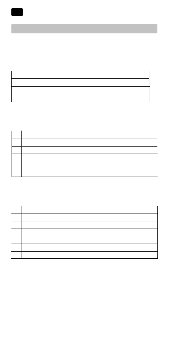
Conventional Systems
Typical Wiring Configurations
NOTE: The “Installer Switch” option will be configured in the next step.
Heat Only or Millivolt
Set Installer Switch to CONV
Rh
Power Connection
W
G Fan Relay [note 4]
C 24 Volt AC Transformer Common [note 1]
Heat Relay (appears as W1/E on PRS3210)
1 HEAT / 1 COOL Single or Dual Transformer
Set Installer Switch to CONV
Rh
Rc
W1
Y1 Compressor Relay
G Fan Relay
C 24 Volt AC Transformer Common [note 1, 3]
24 Volt AC Power (heating transformer) [note 2]
24 Volt AC Power (cooling transformer) [note 2]
Heat Relay (appears as W1/E on PRS3210)
2 HEAT / 1 COOL Single or Dual Transformer
(PRS3210 Only)
Rh
Rc
W1 Heat Relay Stage 1
W2 Heat Relay Stage 2
Y1 Compressor Relay Stage 1
G Fan Relay
C 24 Volt AC Transformer Common [note 1, 3]
24 Volt AC Power (heating transformer) [note 2]
24 Volt AC Power (cooling transformer) [note 2]
Set System Type to CONV
NOTES - Conventional Systems
[1] If batteries are installed the 24 Volt AC common connection is optional
[2] Remove factory installed jumper for dual transformer systems
[3] In dual transformer systems, transformer common must come from
cooling transformer
[4] If needed for system
Provide disconnect and overload protection as required.
2
Page 4

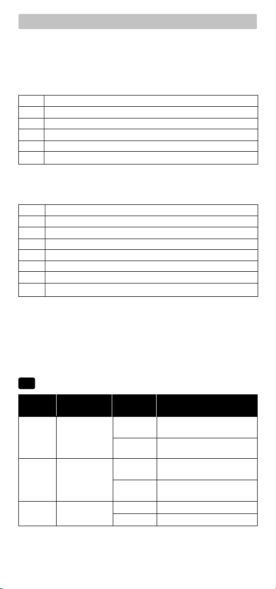
Heat Pump Systems
Typical Wiring Configurations
NOTE: The “Installer Switch” option will be configured in the next step.
1 HEAT / 1 COOL - No Auxiliary Heat
Set Installer Switch to HP
Rh 24 Volt AC Power
Rc Connected to Rh with supplied Jumper Wire
O or B
Changeover Valve [note 2]
Y1 Compressor Relay
G Fan Relay
C 24 Volt AC Transformer Common [note 1]
2 HEAT / 1 COOL - Including Auxiliary Heat
(
PRS3210 Only)
Rh 24 Volt AC Power
Rc Connected to Rh with supplied Jumper Wire
O or B
Changeover Valve [note 2]
Y1
W2 Auxiliary Heat Relay (2nd stage heating) [note 3]
W1/E Emergency Heat Relay [note 3]
G Fan Relay
C 24 Volt AC Transformer Common [note1]
NOTES - Heat Pump Systems
[1] If batteries are installed the 24 Volt AC common connection is optional.
[2] Select O for cool active or B for heat active.
[3] Install a field supplied jumper between the W2 and E terminals if
there is no separate emergency heat relay installed.
Provide disconnect and overload protection as required.
Set Installer Switch to HP
Compressor Relay (1st stage heating/cooling)
4
Set Installer Switches
Factory Setting
Switch Default Options Comments
CONV / HP CONV
F / C F
HE / HG HG
NOTE: The reset button should be pressed after making any changes to the
installer switches.
CONV Select for conventional systems
HP Select for heat pump systems
F Select for fahrenheit temperature scale
C Select for celsius temperature scale
HG Select for gas heat
HE Select for electric heat
3
Page 5
5
Attach Thermostat to Sub-Base
1. Line up the thermostat body with the sub-base.
2. Carefully push the thermostat body against the sub-base until it snaps
into place.
3. Insert quick reference card into slot on top of thermostat.
Setting User Options
3
Advanced User Options
User options allow you to customize some of your thermostats features.
Most users will not need to make any changes to the settings in this section.
To access the User Options menu, hold down both the and buttons
for approximately 3 seconds until the screen changes and displays
the first User Option.
Press the or button to change the setting for the displayed User Option.
After you have made your desired setting, press and together to
advance to the next User Option.
The thermostat will return to normal mode after your last user option is
made or after no keys have been pressed for 15 seconds.
Table of User Options
User Factory Setting
No. Options Default Options Comments
1 1st stage
differential
or 1˚C)
2 2nd stage
differential
(PRS3210
only)
0.5
2.0 1.0, 2.0,
0.5, 1.0
or 2.0 differential of .5˚, 1˚ or 2˚F (.2˚, .5˚
3.0, 4.0
5.0
Select a 1st stage temperature
Select a 2nd stage temperature
, differential of 1˚, 2˚, 3˚, 4˚, 5˚ or 6˚F
or
6.0
(.5˚, 1˚, 1.5˚, 2˚, 2.5˚ or 3˚C)
Detailed Explanation of User Options:
Temperature Differential
(User Option 1 and 2)
The differential setting is the temperature control range that your thermostat
will provide. The smaller the setting, the tighter your range of temperature
control and comfort will be. The 2nd stage differential is only for systems
with a second stage of heating (auxiliary heat).
4
Page 6
Operating Your Thermostat
4
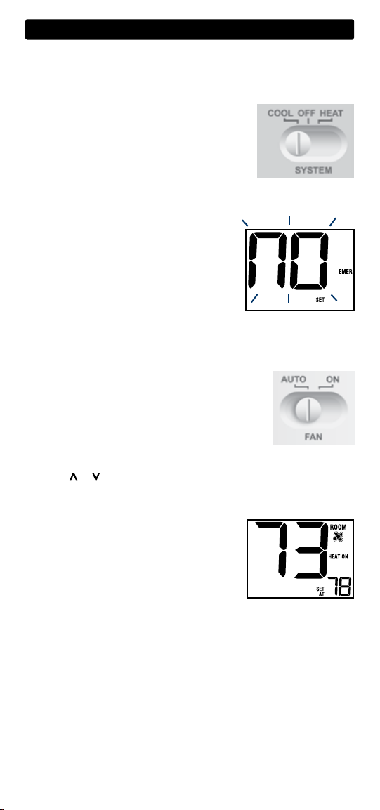
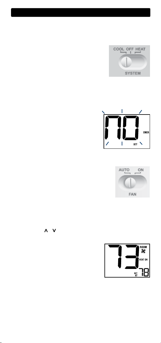
Setting the System Control Mode
The System Control has several modes of operation that can be selected by
moving the SYSTEM switch to the appropriate position.
COOL Only your cooling system will operate
OFF Heating and cooling systems are off.
HEAT Only your heating system will operate.
Additional Switch Position (Model PRS3210 Only):
EMER Operates a backup heat source (Emergency Heat) for heat pump
systems only.
NOTE:
If your model PRS3210 was configured for
a conventional system (CONV) then you will not
have
the EMER (emergency heat) option and “NO
EMER SET” will flash in the display if EMER is
selected with the system switch.
Setting the Fan Control Mode
The Fan Control has 2 modes of operation – AUTO and ON. The mode
can be selected by moving the FAN switch to the appropriate position.
AUTO The system fan will run only when your
heating or cooling system is running.
ON The system fan stays on.
Temperature Adjustment
Press the or button to adjust the current set point temperature.
Status Indicators
Status indicators appear in the display to let
you know if your system is heating, cooling
or off.
HEAT ON
COOL ON
Additional Status Indicators (Model PRS3210 Only):
AUX Indicates that the auxiliary stage of heating is running
(Multi-Stage Systems only).
EMER Indicates that the emergency heating system is running
(Heat Pump Systems only).
Indicates your heating system is running.
Indicates your cooling system is running.
5
Page 7

Resetting the Thermostat
This thermostat provides you with a reset button that will erase all of your
user settings. To reset the thermostat, use a small object such as a tooth
pick or paperclip and gently press the button located inside the small hole
on the front of the thermostat housing labeled “reset”.
Additional Operation Features
5
Compressor Protection
This thermostat includes an automatic compressor protection delay to
avoid potential damage to your system from short cycling. This feature
activates a short delay after turning off the system compressor.
Thermostat Maintenance
6
Changing the Batteries
Depending on your particular installation, this thermostat
may be equipped with two (2) “AA” type alkaline batteries.
If batteries are installed and they become low, a low battery indicator will
appear in the display.
you see the low battery signal by following these instructions.
1. Remove thermostat body by gently pulling it from base.
2. Remove old batteries and replace with new batteries.
3. Make sure to correctly position the (+) and (-) symbols.
4. Gently push thermostat body back onto base.
NOTE: We recommend replacing the thermostat batteries annually or if the
thermostat will be unattended for an extended period of time.
You
should change your batteries immediately when
Thermostat Cleaning
Never spray any liquid directly on the thermostat. Using a soft damp cloth
wipe the outer body of the thermostat. Never use any abrasive cleansers to
clean your thermostat.
Store this manual for future reference.
5 Year Limited Warranty
PROPARTS warrants each new PROSTAT thermostat against any defects that are due
to faulty material or workmanship. This warranty and our liability does not apply to
batteries, nor does it include damage to merchandise or the thermostat resulting from
accident, alteration, neglect, misuse, improper installation or any other failure to follow
PROSTAT installation and operating instructions. This limited warranty applies for the
duration of the warranty period from the original date of purchase by a professional
service technician.
facility.
thermostat under
PRS3110-100-02
PROPARTS agrees to repair or replace at its option any PROSTAT
warranty provided it is returned postage prepaid to our warranty facility in a padded
carton within the warranty period, with proof of the original date of purchase and a
brief description of the malfunction. This limited warranty does not include the cost of
removal or re-installation.
This warranty gives you specific legal rights and you may also have other rights that
vary from state to state or province to province. Answers to any questions regarding our
limited warranty may be obtained by writing our corporate offices.
For warranty service, please visit your nearest PROPARTS
Technical Assistance: 855-445-2466 (U.S.)
All trademarks are the property of their respective owners.
©2018 PROPARTS • All Rights Reserved • Made in China.
Page 8

Manual de
Termostatos No Programables
Usuario
PRS3110
1 Etapa Calefacción / Aire Acondicionado
Convencional y Bomba Térmica
Hasta 2 etapas de Calefacción / 1 de
PRS3210
Aire Acondicionado Convencional y
Bomba Térmica
El número del modelo se encuentra en la parte
posterior
del termostato.
1
Especificaciones
2
Instalación
3
Configuración de las
opciones del usuario
Advertencia
de aire acondicionado o calefacción antes de la instalación.
Atención
Solamente debe ser instalado por técnicos
de servicio experimentados.
4
Funcionamiento de su termostato
5
Características funcionales
adicionales
6
Mantenimiento del termostato
Apague la energía que alimenta el equipo
Lea todas las instrucciones antes de continuar.
Este termostato requiere energía de 24 V de CA o dos (2) baterías
alcalinas tipo “AA” instaladas correctamente para su adecuado
funcionamiento. Al conectar la energía a 24 V de CA, las baterías
se pueden instalar como respaldo. La instalación del termostato y
todos los componentes del sistema deberán conformarse a los
Circuitos de clase II del código NEC.
describe en este manual. Cualquier otro uso anulará la garantía.
Solamente se debe usar como se
Especificaciones
1
PRS3110-100-02
Page 9
Instalación
2
Advertencia
Desconecte la energía antes de empezar a
hacer la instalación.
Ubicación del termostato
Instale el termostato aproximadamente a 1,5 m (5 pies) por encima del
piso en un área que tenga una buena cantidad de aire circulante y mantenga una temperatura ambiental promedio.
Evite la instalación en lugares donde el termostato pueda ser afectado por
corrientes de aire, aire estancado, ductos de aire frío o caliente, luz solar,
electrodomésticos, tuberías ocultas, chimeneas y paredes exteriores.
Instale su nuevo termostato PROSTAT en 5 pasos básicos:
1 Instale la sub-base
2 Suministre energía
3 Conecte los cables
4 Configure los interruptores de instalación
5 Fije el termostato a la sub-base
1
Instale la sub-base:
• Retire la sub-base del cuerpo del termostato.
• Monte la sub-base como se muestra a continuación
UP UP
Perfore agujeros guía
de 4,8 mm (3/16 pulg.)
en el lugar deseado.
Use los anclajes suministrados para láminas
de yeso o masilla.
2
Suministre energía
• Para energía a 24 voltios de CA, debe conectar el lado común del
transformador al terminal C de la sub-base del termostato.
• Para energía primaria o de reserva, introduzca las 2 baterías alcalinas
tipo “AA” suministradas en el compartimiento ubicado en la parte poste rior del termostato. Asegúrese de colocar correctamente los lados positivo
(+) y negativo (-) con los signos +/- del compartimiento de
1
las baterías.
Page 10
3
Conecte los cables
Sistemas convencionales
Configuraciones típicas de cableado
NOTA:
La opción “Interruptor de instalación” se configurará en el siguiente paso.
Calefacción solamente o milivoltaje
Configurar el interruptor de instalación en CONV
Rh
Conexión de la energía
W
G Relé del ventilador [nota 4]
C Línea común del transformador a 24 voltios de CA [nota 1]
Relé de calefacción (aparece como W1/E en el modelo PRS3210)
Transformador doble o sencillo con 1 etapa de calefacción /
1 etapa de aire acondicionado
Configurar el interruptor de instalación en CONV
Rh
Rc
W1 Relé de calefacción (aparece como W1/E en el modelo
Y1 Relé del compresor
G Relé del ventilador
C Línea común del transformador a 24 voltios de CA [nota 1, 3]
Energía a 24 voltios de CA (transformador de calefacción) [nota 2]
Energía a 24 voltios de CA (transformador de aire acondicionado) [nota 2]
PRS3210
)
Transformador doble o sencillo con 2 etapas de calefacción /
1 etapas de aire acondicionado (PRS3210 solamente)
Configure el tipo de sistema a CONV
Rh
Rc
W1 Relé de calefacción etapa 1
W2 Relé de calefacción etapa 2
Y1 Relé del compresor etapa 1
G Relé del ventilador
C Línea común del transformador a 24 voltios de CA [nota 1, 3]
Energía a 24 voltios de CA (transformador de calefacción) [nota 2]
Energía a 24 voltios de CA (transformador de aire acondicionado) [nota 2]
NOTAS - Sistemas convencionales
[1] Si las baterías están instaladas, la conexión común a 24 voltios de CA
es opcional.
[2] Retire el puente instalado en fábrica para los sistemas de doble
transformador.
[3] En sistemas de doble transformador, la línea común del transformador
debe venir del transformador de aire acondicionado.
[4] Si es necessario para sistema
Proporcione protección contra desconexión y sobrecarga según sea necesario.
2
Page 11
Sistemas de bomba de calor
Configuraciones típicas de cableado
NOTA:
La opción “Interruptor de instalación” se configurará en el siguiente paso.
1 etapa de calefacción / 1 etapa de aire acondicionado –
Sin calefacción auxiliar
Configure el interruptor de instalación en HP
Rh Energía a 24 voltios de CA
Rc Conectado a Rh con el cable para puente suministrado
O or B
Válvula de conversión [nota 2]
Y1 Relé del compresor
G Relé del ventilador
C Línea común del transformador a 24 voltios de CA [nota 1]
2 etapas de calefacción / 1 etapa de aire acondicionado –
Incluida calefacción auxiliar (PRS3210 solamente)
Configure el interruptor de instalación en HP
Rh Energía a 24 voltios de CA
Rc Conectado a Rh con el cable para puente suministrado
O or B
Válvula de conversión [nota 2]
Y1
Relé del compresor (1ra etapa de calefacción/aire acondicionado)
W2 Relé de calefacción auxiliar (2da etapa de calefacción) [nota 3]
E Relé de calefacción de emergencia [nota 3]
G Relé del ventilador
C Línea común del transformador a 24 voltios de CA [nota1]
NOTAS - Sistemas de bomba de calor
[1] Si las baterías están instaladas, la conexión común a 24 voltios de CA
es opcional.
[2]
Seleccione O para aire acondicionado activo o B para calefacción activa.
[3] Instale un puente suministrado en obra entre los terminales W2 y E si
no se ha instalado un relé de calefacción de emergencia por separado.
Proporcione protección contra desconexión y sobrecarga según sea necesario.
4
Configure los interruptores de instalación
Valor predeter- Opciones de
Interruptor minado de fábrica configuración Comentarios
CONV Seleccione para el sistema
CONV / HP CONV
F / C F
HE / HG HG
NOTA: Los interruptores de instalación están ubicados en la parte posterior
del termostato. Después de haber realizado cualquier cambio en los interruptores, presione el botón reiniciar.
convencional
HP Seleccione para el sistema de
bomba de calor
F Seleccione para escala de
temperatura de grados Fahrenheit
C Seleccione para escala de tempera-
tura de grados centígrados
HG Seleccione para calefacción a gas
HE
Seleccione para calefacción eléctrica
3
Page 12

5
Fije el termostato a la sub-base
1. Alinee el cuerpo del termostato con la sub-base.
2. Empuje cuidadosamente el cuerpo del termostato contra la sub-base
hasta que encaje en su sitio.
3. Introduzca la tarjeta de consulta rápida en la ranura de la parte superior
del termostato.
Configuración de las opciones del usuario
3
Opciones avanzadas del usuario
Las opciones del usuario permiten personalizar algunas de las características de su termostato. La mayoría de los usuarios no tendrán que hacer, en
esta sección, cambio alguno a lo configurado.
Para tener acceso al menú Opciones del usuario, mantenga presionados los botones y durante 3 segundos aproximadamente hasta
que la pantalla cambie y muestre la primera Opción para el usuario.
Presione el botón o para cambiar la configuración para la Opción del
usuario que se muestra. Después de haber realizado la configuración deseada, presione al mismo tiempo y para avanzar a la siguiente opción
del usuario.
El termostato regresará al modo normal después de la última opción del
usuario o si no se presiona una tecla durante 15 segundos.
Tabla de las opciones del usuario
Valor pre-
Opciones deter
No. del usuario
1 Diferencial de
1ra etapa
(0.5˚, 1˚ o 2˚F)
2 Diferencial de
2da etapa
(PRS3210
solamente) 3˚C (1˚, 2˚, 3˚ 4˚, 5˚ o 6˚F)
minado
de fábrica
0.5
0.5, 1.0
2.0
Opciones de
configuración
or 2.0
1.0, 2.0,
3.0, 4.0
5.0 or 6.0
Comentarios
Seleccione un diferencial
de temperatura de 1ra
etapa de 0.2˚, 0.5˚ o 1˚C
Seleccione un diferencial de
,
temperatura de 2da etapa de
0.5˚, 1˚, 1.5˚, 2˚, 2.5˚ o
Explicación detallada de las opciones del usuario:
Diferencial de temperatura
(Opción del usuario 1 y 2)
La configuración diferencial es la amplitud de control de temperatura que el
termostato le proporcionará. A menor configuración, menor será la amplitud
de control de temperatura y la comodidad. El diferencial de 2da etapa está
destinado solamente a sistemas con segunda etapa de calefacción
(calefacción auxiliar).
4
Page 13
Funcionamiento de su termostato
4
Configuración del modo de control del sistema
El control del sistema cuenta con varios modos de funcionamiento que
pueden seleccionarse al mover el interruptor del sistema a la posición
apropiada.
COOL (aire acondicionado) Sólo funcionará el
sistema de aire acondicionado.
OFF (Apagado) Los sistemas de calefacción y
aire acondicionado están apagados.
HEAT (Calefacción) Sólo funcionará el sistema de calefacción.
Posición de interruptor adicional (para modelo PRS3210 solamente)
EMER
(Emergencia) Activa una fuente de calefacción de respaldo (calefacción
de emergencia) sólo para los sistemas de bomba de
NOTA: Si su modelo PRS3210 fue configurado
para un sistema convencional (CONV), no contará
con la opción EMER (calefacción de emergencia)
y la pantalla destellará “NO EMER SET” (sin
configuración auxiliar) si se selecciona EMER
(emergencia) con el interruptor del sistema.
calor.
Configuración del modo de control del ventilador
El control del ventilador tiene 2 modos de
funcionamiento - AUTO (Automático) y ON (Encendido).
Puede seleccionar el modo moviendo el interruptor
de FAN (ventilador) a la posición adecuada.
AUTO (Automático). El ventilador del sistema
funcionará sólo cuando su sistema de
calefacción o aire acondicionado esté funcionando.
ON (Encendido)
El ventilador del sistema permanece prendido.
Ajuste de la temperatura
Presione el botón o para ajustar el valor predeterminado actual
de la temperatura.
Indicadores de estado
Los indicadores del estado aparecen en la pantalla
para informarle si su sistema está en calefacción,
aire acondicionado o apagado.
HEAT ON
sistema de calefacción está funcionando.
COOL ON (aire acondicionado encendido) Indica que su sistema de aire
acondicionado está funcionando.
Indicadores de estado adicionales (Modelo PRS3210 solamente):
AUX (Auxiliar) Indica que la etapa auxiliar de calefacción está
funcionando (sólo para sistemas multietapa).
EMER
está funcionando (sólo para sistemas de bomba de calor).
(Calefacción encendida) Indica que su
(Emergencia) Indica que el sistema de calefacción de emergencia
5
Page 14

Reinicio del termostato
Este termostato tiene un botón de reinicio (Reset) que borrara toda la
programación del usuario. Para reiniciar el termostato, utilice un objeto
pequeño, como un palillo o un clip y presione suavemente el botón ubicado
dentro del pequeño agujero de la parte frontal de la caja del termostato
rotulado “reset” (reiniciar).
Características funcionales adicionales
5
Protección del compresor
Este termostato incluye un retardo de protección automática del compresor
para evitar posibles daños al sistema provocados por ciclos cortos. Esta
característica activa un corto retardo después de apagar el compresor
del sistema.
Mantenimiento del termostato
6
Cambio de las baterías
Dependiendo de su instalación, este termostato puede estar
equipado con dos (2) baterías alcalinas tipo “AA”.
Si las baterías están instaladas y la carga baja, aparecerá en la pantalla
un indicador de batería baja.
Debe cambiar las baterías inmediatamente
cuando vea la señal de batería baja, siguiendo estas instrucciones.
1. Retire el cuerpo del termostato tomándolo suavemente por la base
y tirando.
2. Retire las baterías viejas y reemplácelas por unas nuevas.
3. Asegúrese de colocar correctamente los signos (+) y (-).
4. Empuje suavemente el cuerpo del termostato de nuevo en su base.
NOTA: Recomendamos el remplazo anual de las baterías o si el termostato
estará desatendido por un periodo largo.
Limpieza del termostato
No rocíe ningún líquido directamente sobre el termostato. Limpie la parte
de exterior del termostato con un paño suave y húmedo. Nunca utilice
limpiadores abrasivos para limpiar el termostato.
Guarde este manual para consultarlo en el futuro.
5 Años de Garantía Limitada
PROPARTS garantiza a cada nuevo termostato PROSTAT contra defectos causados por
material o fabricación defectuosa. Esta garantía y nuestra responsabilidad no es aplicable a
las baterías, ni incluye daños a la mercancía o termostato como resultado de un accidente,
alteración, negligencia, mal uso, instalación malhecha o cualquier otra falla en seguir las
instrucciones de instalación u operación de PROSTAT. Esta garantía limitada es aplicable
desde la fecha de compra original por un técnico profesional.
PROSTAT acepta reparar o reemplazar a su elección cualquier termostato PROSTAT que
se encuentre bajo garantía, siempre y cuando se devuelva, con gastos de correo pagados,
a nuestro centro de garantías en una caja de cartón acolchada, dentro del período de la
garantía, con un comprobante de la fecha original de compra y una breve descripción del
defecto. Esta garantía limitada no incluye el costo de retiro o reinstalación.
Esta garantía le da derechos legales específicos y usted puede tener también otros
derechos que varían de un estado a otro o de una provincia a otra. La respuesta a cualquier
pregunta acerca de nuestra garantía limitada se puede obtener escribiendo a nuestras
oficinas corporativas. Para garantia contacte a PROPARTS.
Teléfono: 855-445-2466 (EE.UU.)
Todos los “trademarks” son propiedades de sus respectivos dueños.
©2018 PROPARTS •
Todos los derechos están reservados.
Hecho en China.
PRS3110-100-02
 Loading...