

ProSpot Fitness PC-1000 User Manual
rM
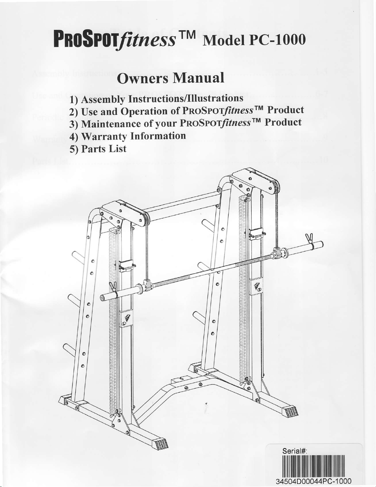
Pno$PoWness
Modet
Pc-tooo
Owners
1) Assembly
2) Use
Maintenance
3)
4) Warranty
5) Parts
and
Operation
List
Manual
Instructions/Illustrations
PnoSYor/itnessrM
of
your PnoSrory'tzessrM
of
Information
Product
Product
Serial#:
ililil ililtililrilililil||il||il
34504D00044PC-1000
ilillililllililll
Table
of
Contents
Assemblylnstructions.
Use and
Periodic
Warranty Information.
Parts
Operation of Your PROSPOUtnessrM
Maintenance
List....
of
your
Product......
PROSPOffrnessrM
Product......................8
..........1-5
.....,..........6-7
.........9
..... 10
lnstructions
for
Assembly
of the PROSPOTItnessrM PC-1000
.
Before
'1000
PROSPOTlrressrM
or spilled on any electrical
.
Approximate assembly time is 1/2
o
A flat area of 8' x 8'will be
.
You will need the following tools
.
Floor Padding, such as cardboard, to avoid scratching
.
A
caTtons.
o
HAND TIGHTEN
.
Before assembly, separate
distinguished by the
"L"&"R"stickers.
assembly, choose a safe
has a footprint of approximately 6'x
PC-'|000
.
5 mm Allen
.
14 mm Box End
.
17 mm Box End Wrench
.
19 mm Box End
good pair
of scissors
Wrench
Wrench
Wrench
will be helpful in separating the
bolts. DO NOT fully tighten
all
manner in which
location for
from any source of
away
part.
Do not insert any object
hours.
required to assemble and
and a helper to complete the assembly:
and identify the righfsided
your
pre-drilled
the
PROSPOFJitnessrM PC-1000. The PROSPOTlrressrM PC-
6'. The barbell is approximately 7' long. Locate
water. Do not
into the electrical
properly
your
bolts
until
holes align with corresponding
use the
floor during assembly.
parts
from
instructed
parts
from
allow any
PROSPOTlrtersrM
one another while removing them from
to do so.
left-sided
the
box.
liquid
parts.
parts.
to be
PC-1000.
These
or are
near
the machine
parts
identified
are easily
your
the
by
.
The PROSPO"ffitnessrM
of bolt called for at each step of assembly.
r
WARNING: Never
PC-l000 while the Power Supply
PC-1000 uses several different lengths of bolts. Be careful
Refer to the sizing charts
perform
any
maintenance
plugged
is
STEP # 1: MAIN FRAME ASSEMBLY
1. Place the two Base Rails
lllustration. Place the Lower Cross Brace
holes of the Base Rails
2.
Carefully
Base Rails
3. Attach the two Base Rails
bolts
4. Attach the Right
Support Plate
as shown.
5. Attach the Left Upright Guidepost Assembly
Support Plate
as shown. HAND TIGHTEN the bolts at this time.
thread the Cross Brace Wire Harness
(1
& 2) then
(22),
washers
eight
Upright Guidepost
(6)
attached on the right base rail
HAND TIGHTEN
(6)
attached on the left base rail
(1
2) opposite each other in the center of the assembly
&
(3)
between the two Base Rails
(1
& 2) align with the end holes of the Lower Cross Brace
(8)
through the corresponding
pull
Wire Harness
the
(1
& 2) to the Lower Cross Brace
(18)
and four nuts
Assembly
the bolts at this time.
(8)
out of the top
(20)
as shown. HAND TIGHTEN the bolts
(7,
10,23\
(1)
using two bolts
(9,
12,23) to the Lower Cross Brace
(2)
using two bolts
provided.
on the PROSPOT/itnesslM
into the wall !!!
(1
holes
of the Base Rails
(3)
using two Upright
to the
Lower
(22),
(22),
Cross Brace
four washers ( 18)
four washers ( 18)
to use the correct length
area as shown in the
& 2) so that the
(3).
pre-drilled
side
('l
& 2).
Support Plates
at this time.
(3)
and
and two nuts
(3)
and the Upright
and two nuts
pre-drilled
side
holes
(6),
the Upright
of the
four
(20)
(20)
6. Plug
just
under the
together both
perforated
of the Cross Rail Wire Harness
Slider Shields on back
of the Screen Panels
__1__
(8)
to lower ends of the
Spiral Signal Cables
(23).
(46)
Iocated
7. Attach
and four nuts
the two
Rear Support
(20)
as shown.
Frames
HAND TIGHTEN the
(4)
to the two base
bolts
rails
this time.
at
(1
& 2) using four bolts
(22),
eight washers
(18)
8. Attach the two
12) using eight bolts
&
at this time.
Attach
9.
(18)
'10.
Tighten all bolts and nuts used
11. Carefully
grooves
that the cables are
12. Repeat the step
STEP
1.
2. Place one Plastic Locking Sleeve
the
and four nuts
Frame
(17)
#2:
Standing
Weight Bar
preinstalled
the
rotation limi{ing
in the knuckles
until they butt up against and secure
bolts securely.
Pulley Support Frames
(28),
sixteen washers
Upper Cross Brace
(20)
as shown.
insert the Left Weight Bar
and flex the Left
each corresponding
of
straight and uncrossed and
11
on the
SENSOR
in front of the PROSPOTlrressrM
(25)
into the Knuckles
sensor retaining collars
pin
that
g?
A 44t as
(11)
HAND TIGHTEN the bolts
for assembly
Weight Bar Cables
pulleys
right
side
WEIGHT BAR
protrudes
it
is slid
(17)
two Rear Support
to the
Knuckle
and allowing
of the PROSPOT/nsssrM
Rear Support Frames
to the
(18)
and
eight
previous
in
(44)
up through the rectangular cutout in the Pulley Support
(24)
onto the
the Left Weight Bar Knuckle
cables and
nuts
Frames
at this time.
steps.
pulleys (27)
pulleys
PC-1000.
(4)
and the Upright Guide Posts
(20)
as shown. HAND TIGHTEN
(4)
using
so that the cables
move smoothly.
INSTALLATION
PC-1000. Insert one end and
(42
44). Slide the knuckles onto the Bar until they rest snugly
&
(45
& 48) at each end of the Sensor Weight Bar
from the bottom of the Sensor Weight Bar
position).
into
(39)
each end of the Sensor Weight Bar
onto
the Weight Bar Cable
Knuckle
place.
in
then the
(10
the bolts
four bolts
(44)
(25)
(25)
Tighten Plastic Locking Sleeve
(51),
eight washers
insert
into the
to hang free. Be
other
that must fit through
and slide them inwards
of the
end
(25). (There
Sensor
against
sure
is
a slot
a
3. Place one of the Olympic Adapters
they touch the Plastic Locking Sleeves
of the Sensor Weight Bar
Allen
4. Attach the four small
washers
Attach
5.
twenty-four washers
6.
Carefully thread the
Electronic Box Locating
using two bolts
7. Attach
lwo washers
(29),
bolts
(38)
the six Side Weight Plate
the
two washers
and four nuts
(22),
Electronic Box Protecting Cover
(57)
as shown. Tighten the screws
(25)
plastic pipes (15)
(35)
(18)
and twelve nuts
rear
ends
Plate
four
washers
(30)
onto the Sensor
(39).
Insert an Olympic Adapter Retaining Plug
so that they also
(36)
and two spring
to the two
as shown.
Holders
of the Cross Brace Wire
(13)
(18)
Tighten the
(14)
(20)
then attach the Locating Plate
and
and two
go
washers
to the two Rear Support Frames
as shown. Tighten the bolts securely.
nuts
(5)
to the
securely.
Note: In this manual when referring to Left and
are from
outside, facing
the
front of the unit.
the
Weight Bar
inside of the Olympic Adapters
(56).
Pulley
Support
bolts securely.
Harness
(20).
Tighten the bolts securely.
Locating Plate
Right
side of unit, the left and right
(25)
and slide them onto the Bar until
Frames
(17)
using
(4)
(8)
through the middle hole
(13)
to the Lower
(13)
using two cross screws
(33)
(30).
four
using
twelve bolts
onto each end
Secure with two
(34),
bolts
Cross Brace
eight
(53),
on the
(52)
(3)
and
perspective
--2--
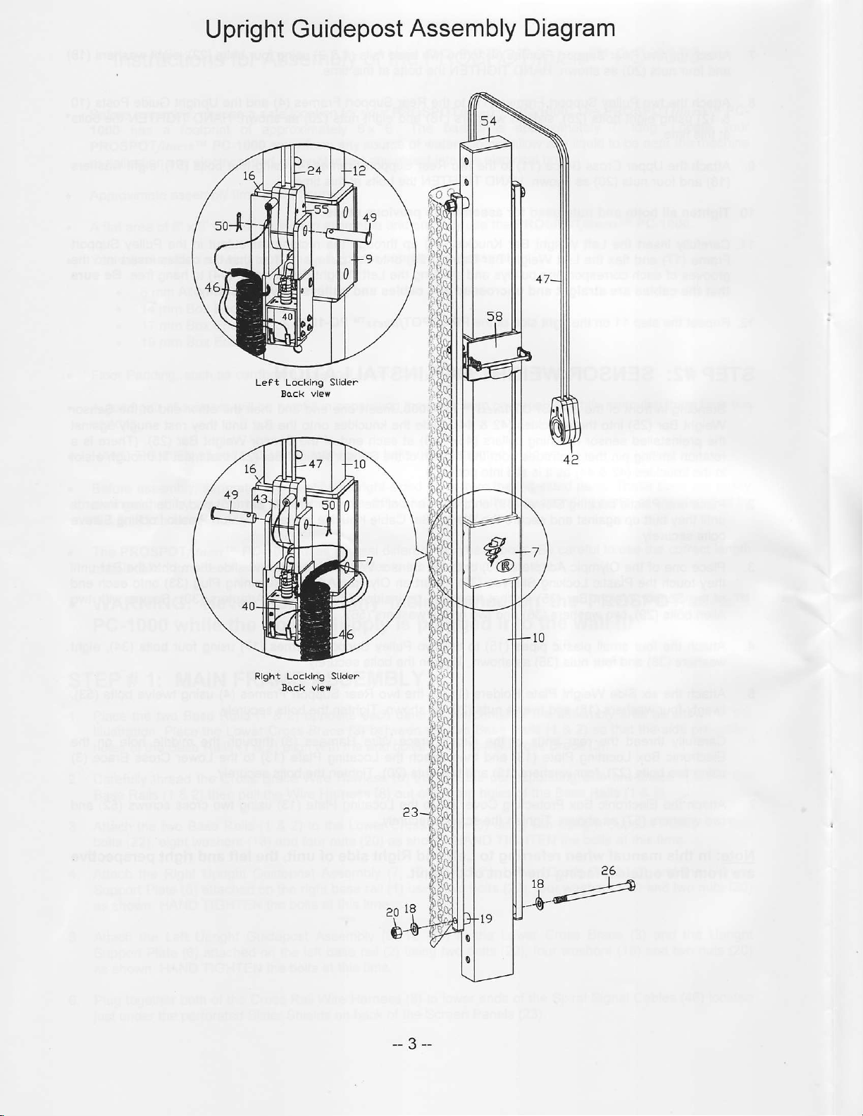
Upright Guidepost
Left Locklng Stlder
Assembly
Diagram
Rlght Locklng Stlder
Bock vlevr
--3--
 Loading...