

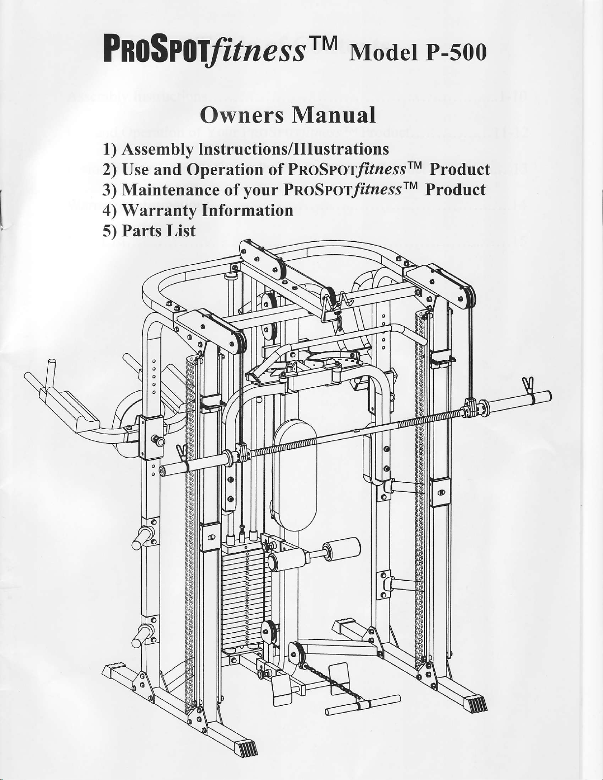
ProSpot Fitness P-500 User Manual
PnoSP
olfitne,ss
rM
Moder P-5oo
Owners
1) Assembly lnstructions/Illustrations
2) Use and Operation of
Maintenance
3)
4) Warranty Information
5) Parts
List
of
your
Manual
PnoSrorf/zessrM
PnoSroty'lzessrM
Product
Product

Table
of
Contents
Assembly
Use and
Periodic
Warranty
Partslist....
Instructions.
Operation
Maintenance
Information.
of Your
your
of
PnoSroffrnessrM
pnoSror/aessrM
product.
. .
. . . . .
product.
. . ..
........1_10
. .......1
. .
.. . .
...........15
_12
|
.....
. I 3
.....14

lnstructions for Assembly
of the
PROSPOT/tnessrM
P-500
.
Before assembly, choose a safe location for
P-500 has a footprint
PROSPOTlrzessn P-500 away from any source
machine or spilled on any electrical
.
Approximate
.
A flat
area of 9' x 9' will be required to assemble and
.
You will need
.
5 mm Allen Wrench
.
14 mm Box End Wrench
.
17 mm Box End Wrench
.
19 mm Box End Wrench
.
Floor Padding,
.
good pair
A
them from the cartons.
r
HAND TIGHTEN
.
Before
easily
distinguished by
identified
assembly time is 1-1l2 hours.
the following tools and a helper to complete
assembly, separate
"1"
by
&
of approximately 8'x 8'. The barbell is
part.
Do not insert
as cardboard,
such
of scissors will be helpful in separating
all bolts. DO NOT fully
and identify the right-sided
manner
the
"R"
stickers.
to avoid scratching
tighten bolts until instructed
in whjch the
your
PROSPOTJitnessrM
water.
of
any object into the
properly
parts
pre-drilled
Do not allow
use the PROSPOT/itressrM
the assembly:
your
floor during assembly.
parts
the
from the left-sided
holes align with
P-500. The PROSPOTlrzessn
approximately 7' long.
liquid
any
electrical box.
from
one another while
to do so.
parts.
corresponding
Locate
to
be near the
P-500.
These
rals :- a.e
your
re-:, 19
.61s a-e
o
The PROSPOTfitnessrM
length
of bolt called for at each
o
WARNING:
Never
while the Power
P-500 uses several
step of assembly. Refer to
perform
Supply is
any maintenance
plugged
different lengths
the sizing charts
on the PROSPOffiressn
into
the watl
!!!
of bolts. Be careful to use
provided.
:^e ::..e.t
P-500
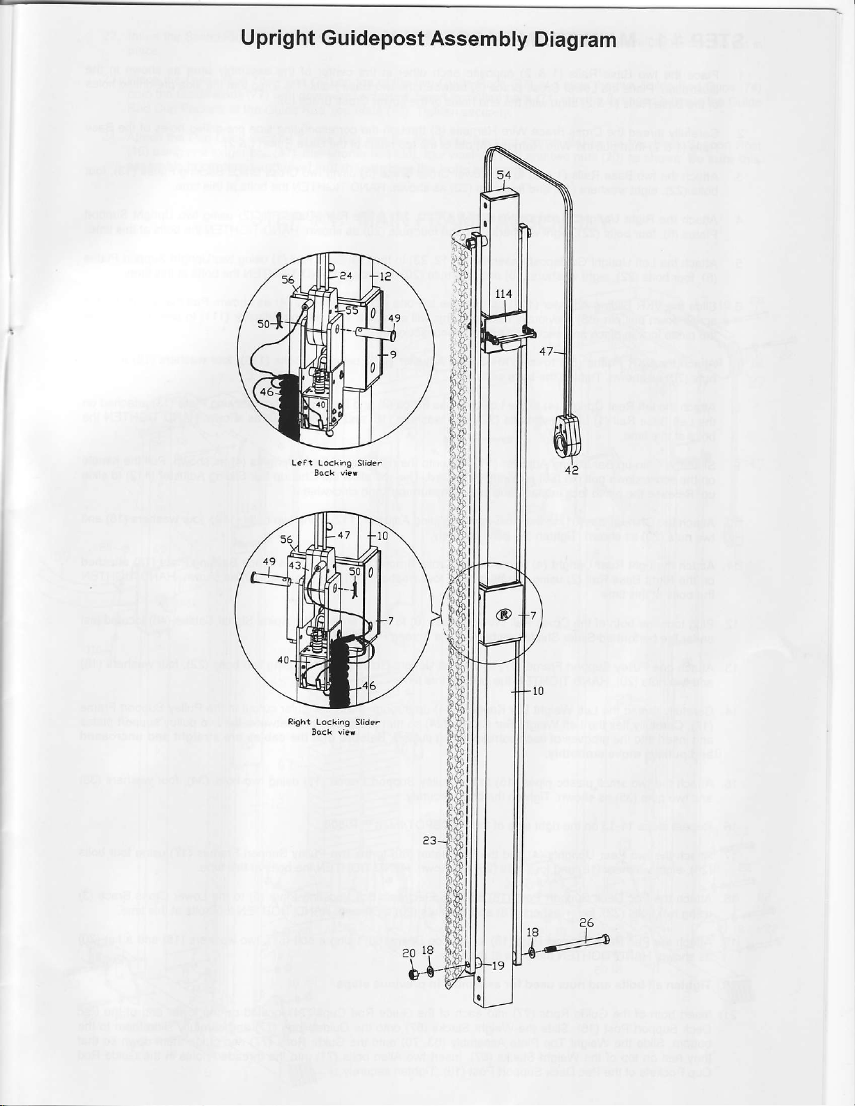
Upright
Guidepost
Assembly
Diagram
Leat Locki.g Slide.
Right
Lockihg Sli.te.
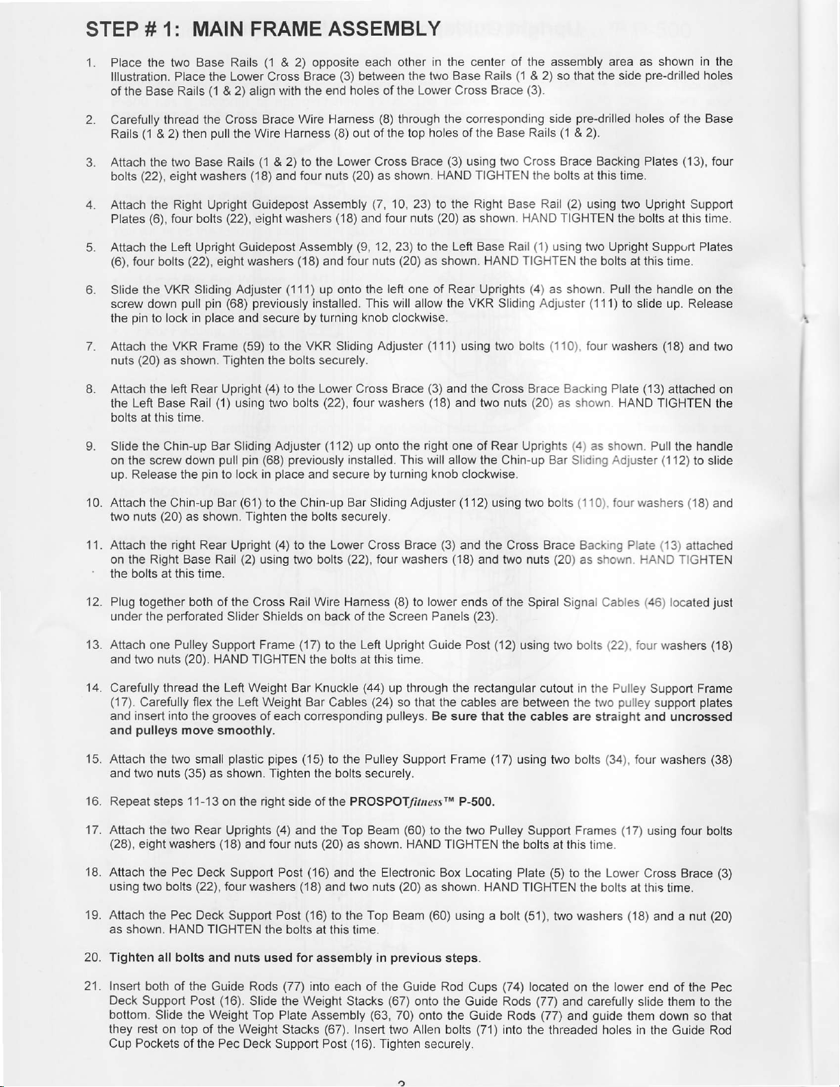
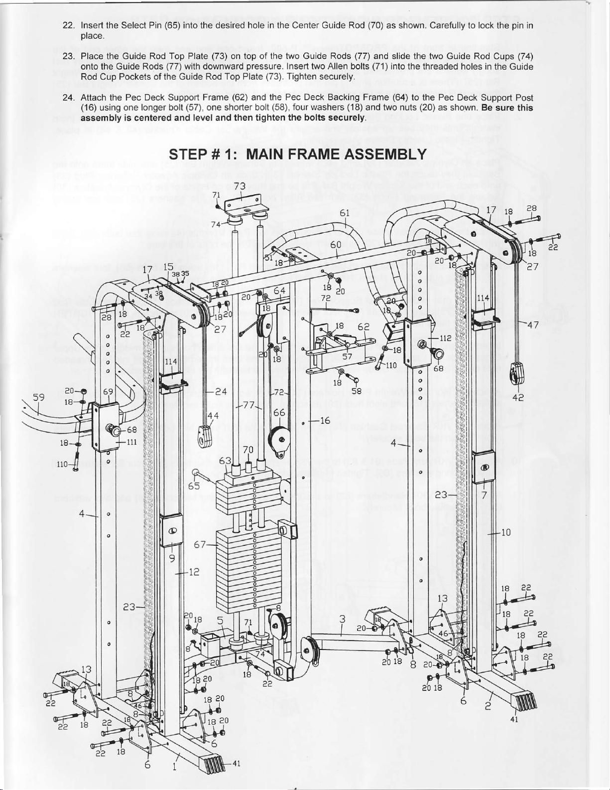
STEP # 1: MAIN FRAME ASSEMBLY
1. Place the two
lllustration. Place the Lower Cross Brace
Base Rails
of the
2. Carefully
3. Attach the
4. Attach the
5. Attach the
6. Slide the
7. Attach the VKR Frame
8. Attach the left Rear Upright
9. Slide the Chin-up Bar Sliding Adjuster
(1
Rails
(22),
bolts
(6),
Plates
(6),
four
screw down
pin
the
to
(20)
nuts
the Left Base Rail
bolts at this time.
on the screw
up. Release the
Base Rails
(1
thread the Cross
& 2) then
eight
bolts
VKR Sliding Adjuster
lock
as shown.
pull
two Base Rails
washers
Right Upright Guidepost
four bolts
Left Upright Guidepost Assembly
(22),
eight washers
pull pin
place
in
(1)
pull pin
down
pin
to lock in
(1
& 2) opposite each other
& 2) align with the end
Brace Wire Harness
Wire Harness
the
(1
2)
&
('18)
(22),
eight
previously
(68)
and secure
(59)
Tighten the bolts securely.
using two bolts
to the
and four nuts
Assembly
washers
(18)
('111)
up onto
installed. This will allow the
by turning knob clockwise.
VKR Sliding Adjuster
to the
(4)
to the Lower Cross
previously
(68)
place
and secure by turning
(3)
between the two
holes of the Lower Cross Brace
(8)
(8)
of the top holes of the Base
out
Lower Cross Brace
(20)
as shown.
(7,
(18)
and four
(9,
12, 23) to the Left Base Rail
four nuts
and
the left one of Rear Uprights
(22),
four washers
(1
12) up onto the right one
installed.
in the center of the assembly area as shown
Base Rails
through
10, 23\ to the Right Base
(20)
Brace
This will allow the Chin-up Baf S
the
corresponding
(3)
using two Cross
HAND TIGHTEN the bolts at this time.
(20)
nuts
as shown.
as shown. HAND TIGHTEN the bolts
(111)
using
(3)
and lhe Cross
(18)
and two nuts
knob
clockwise.
(1
HAND TIGHTEN
VKR
Sliding Adjuster
bolts
two
Rear Uprights
of
2) so
&
(3).
side
Rails
Rail
(1)
using
(4)
as shown. Pull the handle
(110)
Brace Backlng Plate (13)
(20)
the side
that
pre-drilled
(1
& 2).
Brace Backing Plates
(2)
using two Upright Support
two
(11'l)
four washers (18)
as shown.
(4)
as shown Pull the handle
id ng Adtuster (1
pre-drilled
holes of the Base
the bolts at this time.
Upright
Suppurt Plates
at this time.
to slide
HAND
TIGHTEN
in the
holes
(13),
four
on the
Release
up.
and
two
attached on
the
'12)
to slide
10. Attach the Chin-up Bar(61) tothe Chin-up BarSliding Adjuster
two nuts
1 1 . Attach the right Rear Upright
on the Right Base Rail
the bolts at this time.
12. Plug
under the
'13.
Attach one Pulley
and two
'14.
Carefully thread the Left Weight Bar Knuckle
(17).
and insert into the
and
15. Attach
and two nuts
16.
Repeat steps 11-13 on the right side of
'17.
Attach
(28),
18. Attach
using
(20)
as shown.
together
Carefully flex the Left Weight Bar Cables
pulleys
eight washers
two
both of
perforated
(20).
nuts
move smoothly.
two small
the
(35)
the two Rear Uprights
Pec Deck
the
bolts
(22),
Tighten
(2)
the
Slider Shields on back of the Screen
Support
HAND TIGHTEN
grooves
plastic pipes
as shown. Tighten
(18)
and four nuts
Support Post
four washers
the bolts securely.
(4)
to the Lower Cross Brace
using two bolts
Cross Rail Wire Harness
(17)
Frame
of each
corresponding
(15)
(4)
and the Top Beam
(18)
(22),
to the
the bolts at this time.
to the
the bolts
PROSPOTlirrressrM P-500.
the
(20)
as shown. HAND
(16)
and the Electronic Box Locating
and two nuts
four washers
(8)
to
Left
Upright
(44)
up through
(24)
so that the cables
pulleys.
Pulley
Support
securely.
(60)
(20)
(3)
(18)
lower
Panels
Guide Post
the
Be sure
Frame (17)
to the two Pulley
TIGHTEN
as shown.
(1
1 2) using two bolts ( 1 1
and the Cross Brace Backrng Plate
(20)
and two
ends of the Spiral Signal Cables
(23).
rectangular
that the cables are straight and
HAND TIGHTEN the bolts
nuts
(12)
using two bolts
cutout in the Pulley
are between the iwo
using
two bolts
Support Frames
the bolts
Plate
this
at
(5)
to the Lower
fourwashers
0)
as sholvn
(22).
puliey
(34).
(17)
time.
at this time.
HAND TIcHTEN
(46)
four
Support Frame
four
using four
Cross Brace
('18)
(13)
attached
located
washers
support
uncrossed
washers
and
just
(18)
plates
(38)
bolts
(3)
19. Attach the Pec Deck
as shown. HAND TIGHTEN
20. Tighten
21.
Insert both of the
Deck Support Post
bottom. Slide the Weight Top
they rest on top of the Weight
Cup Pockets of the Pec Deck
all bolts and nuts used for
Guide
(16).
Support Post
the bolts at this time.
Rods
Slide the Weight Stacks
(16)
to the Top Beam
assembly
(77)
into each of the Guide Rod Cups
Plate Assembly
Stacks
Support Post
(67).
(60)
using
previous
in
(67)
(63,
70) onto the Guide Rods
Insert two Allen bolts
(16).
Tighten securely.
onto
steps.
the
(51),
a bolt
(74)
located
Guide Rods
(71)
into
the threaded holes in the Guide Rod
two washers
on the lower end
(77)
and
(77)
carefully
and
guide
(18)
and a nut
of the
slide
them to the
them down
(20)
Pec
so that
Insert
place.
the Select
Pin
(65)
into the desired
hole in the
Center Guide
Rod
(70)
as shown. Carefully to lock the
pin
in
23.
Place
the Guide
the Guide Rods
onto
Rod Cup Pockets of the Guide
24.
Attach the
(16)
using one
assembly
Rod Top Plate
Pec Deck Support Frame
longer bolt
is centered and level and then tighten
(73)
on top of the two Guide Rods
(77)
with downward
Rod Top Plate
(57),
one shorter bolt
pressure.
(62)
and the
(73).
(58),
STEP # 1: MAIN
(77)
and slide the two Guide
lnsert two Allen bolts
Tighten securely.
Pec Deck Backing Frame
four washers
the bolts securely.
FRAME
(71)
(18)
and two nuts
ASSEMBLY
into
the threaded holes in
(64)
to the Pec Deck
(20)
as shown.
Rod Cups
the Guide
Support Post
Be sure
(74)
this
e0
18
69
a3-
 Loading...