

Page 1

PR-8
Instruction Manual
2000-08
US
GB
- approved
Page 2

Pro Spot PR-8
Preface
You have just bought a Pro Spot PR-8.
The use of microprocessor control in our vehicle body welding equipment has
many benefits. It means, for example, that a wide range of features is available to
the operator.
The microprocessor is programmed in the same way as an ordinary computer. It
includes software that enables the operator to control energy input to suit the
particular application or conditions. Repair work quality can be checked with an
acoustic signal, while a display helps the operator to control and set up the
machine.
Read this instruction book to appreciate how versatile the Pro Spot PR-8 is.
The photographs and drawings in this manual are merely illustrative and do not necessarily
represent the actual appearance of equipment available. The equipment is designed to be
used in accordance with established practices and in observation of applicable safety regulations. The design of the equipment presented in this manual may be changed without
prior notice.
GB/US/2000-08 PRO SPOT
- 1 -
Page 3

Pro Spot PR-8
Contents
A. Safety
A1 Warnings, important notes
and information 3
A2 Safety signs 4
A3 Placement of safety signs 5
B. Installation
B1 Connection to the power unit 6
B2 Maintenance 6
C. Function selection
C1 Operating mode 7
C2 Control pushbuttons (modes 1-5) 7
C3 Control pushbuttons (mode 6),
automatic program 8
D. Operation
D1 Welding tools 9
D2 Mode selections 9
- Swaging, heating – graphite arc tool 9
- Washer, stud and single-sided welding 9
- C & X tongs, double-sided spot welding 9
- Automatic control and special programs 10
D3 Fitting the welding device 12
D4 Fitting the earth connection 14
D5 Welding gun with single electrode 15
D6 Setting the welding current 16
E. Trouble shooting
E1 Welding problems 17
E2 Error list 18
F. Technical specification
F1 Technical data 19
F2 Block Diagram 20
F3 Diagram 21
GB/US/2000-08
G. Spare parts 23
H. C-tong Situations 27
- 2 -
PRO SPOT
Page 4
Pro Spot PR-8
A. Safety
A1. Warnings, important notes and information
Follow these safety rules to ensure safety for the operator and other persons.
In addition to the safety signs shown on page 5, the following warnings and important notes
will be found elsewhere in these instructions.
Warning! Make sure you know where fire extinguishing
equipment is.
Important! Risk of damage to materials close to the weld,
e.g. glass or textiles.
Important! Ensure that all electrical equipment within the working
area is disconnected. Beware risk of interference.
Important! When in Operating Mode 4, the earth connection
must be made to the supporting body sheet and not to the part to
be welded.
Important! The user must have the necessary knowledge for
use of this equipment.
REMEMBER GENERAL FIRE SAFETY!
Pay attention to the fire safety regulations. Welding is always classified as a fire risk
operation.
Welding where there is flammable or explosive material is strictly forbidden.
Remove flammable material from the immediate vicinity of the welding site.
Fire extinguishers must always be on site where welding is taking place.
NOTE: Sparks may cause fire many hours after completion of welding.
WATCH OUT FOR THE MAIN VOLTAGE!
Take care of the cables - the connection cable must not be compressed, touch sharp edges
or hot work pieces.
Faulty cables are always a fire risk and highly dangerous.
Do not locate the welding machine on wet surface.
GB/US/2000-08 PRO SPOT
- 3 -
Page 5

Pro Spot PR-8
A. Safety
A2. Safety signs
Blue with white symbol.
Directive - Prescribes a specific obligation
Yellow with black symbol.
Warning - Warning for danger.
Undamaged safety signs must always be positioned at the places indicated.
If any sign is damaged or missing, the user must ensure that it is immediately replaced by a
new sign. Safety signs are available as spare parts.
Warning: Appropriate eye protection
must be worn when using this equipment.
Protective gloves, clothing and shoes
must be worn when using this equipment.
Warning: Risk of tripping: loose hoses, cables etc.
Warning: Sparks from welding could start a fire.
Warning: All electrical work on the power unit (connec-
tion, service and installation) must be performed only by
authorized personnel. Disconnect the supply before performing any service or installation work.
GB/US/2000-08
- 4 -
PRO SPOT
Page 6

Pro Spot PR-8
A3. Placement of safety signs
A. Safety
GB/US/2000-08 PRO SPOT
- 5 -
Page 7

Pro Spot PR-8
B. Installation
B1. Connection to the power unit
Warning: All electrical work on the power unit (connection,
service and installation) must be performed only by authorized
personnel. Disconnect the supply before performing any service
or installation work.
Make sure that the voltage shown on the machine rating plate is the same as that of your
supply.
Connect the equipment to a supply socket capable of supplying the power required
The main supply cable must be of such a size as to ensure that it does not overheat when the
equipment is in use.
USA / Canada Other countries
Supply protection:
Voltage/Power: 3 phase 208-240Volt / 60 A 3 phase 208-240Volt / 60 A
Cable area: 20mm
conductor
Circuit Breakers Residual Current Device
3 phase 400-440Volt / 40 A 3 phase 400-440Volt / 40 A
2
per conductor 10mm2 per conductor
> 380Volt 6mm
2
per
Degrees of protection: IP 23 IP23
Connection to the compressed air system
The equipment requires a compressed air supply at 6-8 bar. This must be clean, oil-free and
moisture-free air.
Connect the Pro Spot PR-8 to the compressed air system via the connection on the rear
panel of the machine, using a standard compressed air connector.
The Pro Spot PR-8 is now ready for use.
B2. Maintenance
The amount of use and the working environment should be taken into consideration when planning the
frequency of maintenance of the machine. Careful use and preventive maintenance will help to ensure trouble
free operation.
Daily maintenance: Check the condition of tongs, air connections and air hoses to prevent overheating
and mailfunction due to bad cooling.
Check the condition of tongs and welding cables, do not use faulty cables!
Make sure that the main connection cables in use are safe and according to laid
down regulations. The repair and mounting of main connection cables should be
carried out by an authorized electrician.
Clean all oxidized parts of the tongs, electrodes and connections and tighten the
loosened ones.
Regular maintenance: Pro Spot service repair shops make regular maintenance.
Cleaning the machine
Checking and maintenance of connections, welding tools and electric connections.
Checking of main cable and plug.
Damaged parts or parts in bad condition are replaced by new ones.
Maintenance testing. Operation and performance of the machine are checked.
GB/US/2000-08
- 6 -
PRO SPOT
Page 8

Pro Spot PR-8
C. Function selection
C1. Operating modes Front panel
1. 2.
The Pro Spot PR-8 has six operating modes, as follows:
1. Swaging (graphite arc tool) for thermal straightening of damaged bodywork.
2. Washer welding for slide-hammer tool (pulling out dents.)
3. Stud welding for welding various types of studs, rivets, etc.
4. Single-sided spot welding for welding body parts without tongs.
5. Tongs (double-sided spot welding) for welding with C or X tongs.
3.
4. 5.
6.
6. Automatic Control and special programs.
C2. Control pushbuttons (modes 1-5)
7. Ten LEDs (four green, three orange and three red). For indication of power output.
8. See below.
Press + Plus to increase output power.
+ ”
”
”
- ”
” v ”
NB: When operating in Mode 3, text will
be shown on the display for rivets, studs etc.
Press – Minus to decrease output power.
Acknowledge/cancel messages or faults
with V (reset).
”
s ”
GB/US/2000-08 PRO SPOT
Press S to select operating modes.
- 7 -
7.
8.
Page 9

Pro Spot PR-8
C. Function selection
C3. Control pushbuttons in Mode 6, Automatic Program
Don’t forget to connect the welding cables and control cable. When using tongs, connect the
air hose on the welding cable to the air supply connection on the front panel.
s ”
”
”
+ ”
”
- ”
” v ”
Pressure gauge
Push S to select operating mode.
Push + Plus to select program.
Push – Minus to select program.
Push V to reset alarm signals.
Air
Main On/Off switch
Welding cables
Pressure Regulator
GB/US/2000-08
Cooling air
- 8 -
Trigger connection
& measurement
PRO SPOT
Page 10
Pro Spot PR-8
D. Operation
D1. Welding tools
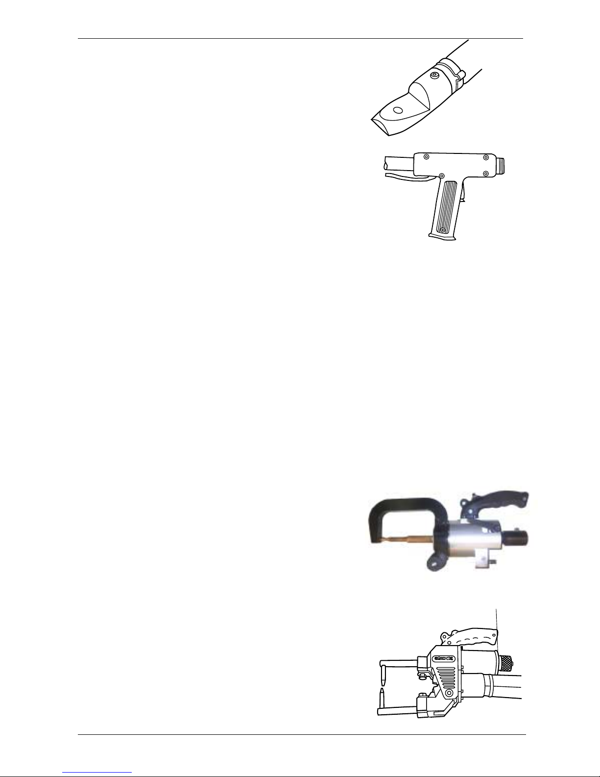
The PR-8 has two 150 mm² screened, air-cooled welding
current cables, with connectors for the welding tool to be
used.
Select the welding tool(s) that is/are suitable for the repair
work to be performed.
D2. Mode selection
There are six different operating modes, each with ten
programs.
Select the required operating mode by pressing the S
pushbutton.
Select the required program and/or output power using the
+ pushbutton.
Description of operating cycles:
Operating Mode 1 (swaging, heating – graphite arc
tool)
Current flows when the operator presses the trigger.
Current stops when the operator releases the trigger.
Operating Modes 2, 3 and 4 (washer, stud and
single-sided welding)
When pressing the trigger, the welding cycle starts and
stops automatically. Keep the pressure on the tool until the
machine shows the goahead signal.
Operating Mode 5 (C and X tongs, double-sided spot
welding)
Pressing the trigger starts the following programmed
sequence:
- Current flows after a half-second delay when the operator presses the trigger. This is referred to as the squeeze
sequence.
- The welding electrodes close.
- Welding current flows.
- The electrodes are held closed to ensure a reliable spot
weld.
Nut
Release the trigger to release the welding electrodes and
move them to the next position. Turn the nut on the rear of
the pneumatic cylinder to adjust the width of opening of the
tongs. Turn the nut anti-clockwise to increase the opening
and clockwise to decrease it.
GB/US/2000-08 PRO SPOT
- 9 -
Page 11

Pro Spot PR-8
D. Operation
D2. Mode selection (continued)
Operating Mode 6: Automatic and special programs
At Power On of the machine it is possibly to see the
default calibration value for a short time in the display.
If the calibrationvalue set from the factory is to be
changed, se instructions below.
NOTE! Do the calibration in Mode 6 with 1 diode ON. It’s
always better to calibrate at low power.
Select the required program by pressing the + or - button
until the correct program is shown on the display .
Calibration for AC1 and AC2
Important! Concerns the two programs, whose text on
the display start with AC1 and AC2.
- Press the + and – pushbuttons at the same time.
- The display shows CALIBRATION.
- Push the trigger on the tong.
- Read the message on the display. If there is no error
message (such as ‘CLEAN ELECTRODES’), and if a
value of 195 - 205 µOhm is shown, conditions are
correct.
- Finish calibration by pressing V
or if the value needs to be changed press + or - to get
the correct value. Store the new value by pressing S.
The text MEM is displayed and finish calibration by
pressing V.
Now it is possible to use AC1 (metal thickness 0.5 - 1.9
mm) or AC2 (1.0 - 3.0 mm) and let the PR-8 compensate
for different metal thickness.
The display and the beep indicate the quality of each
weld (correct spot weld, defective spot weld, too high
power).
Signals during operation:
Acoustic signals allow the operator to concentrate on the
welding, telling him of the quality of the welds.
1.
Strident signal: correct weld.
2.
Muffled signal: defective weld (see E1, Welding
problems).
z Further information in all cases is shown on the display.
Why changing the calibration
Value?
Depending of how powerful the main
supply is there is sometimes a need
for a change of the calibration value.
If the machine is to powerful:
Increase the calibration value with 10
units and test.
If the machine is to weak: Reduce
the calibation value with 10 units and
test.
Only for AC1 and AC2
GB/US/2000-08
- 10 -
PRO SPOT
Page 12

Pro Spot PR-8
D. Operation
D2. Mode selection (continued)
The Automatic Control System.
The machine monitors the resistance of the weld as the weld current builds up, stopping
the current when a correct weld has been achieved.
The machine generates an error signal when a defective weld has been made.
ACE program suits best when there is a lot of similar welding points (same thickness) to
weld, the program will compensate for the temperatur raise (transformer, cables and tong)
and put out more power.
AC1 / AC2 program is more sensitive and need a calibration (ref. D2). The program works
good when welding different sheet thickness.
Special program
Select the special program by pressing the + button. The selected program will be shown
on the display (1).
1.
GB/US/2000-08 PRO SPOT
- 11 -
Page 13

Pro Spot PR-8
D. Operation
D3. Fitting the welding device
1) Stud holder:
Two sizes of stud holders are supplied with
the PRO SPOT PR-8. Select the correct
holder to suit the size of stud to be welded,
and fit it using the brass nut supplied.
2) Conducting probe (graphite arc):
Fit this in the same way as the stud holders.
The welding devices, studs and washers can
be stored on the tool chart.
3) Tongs for double-sided welding:
The tongs can be connected to the same
welding cables, which means that they can
be changed without having to change the
cables.
GB/US/2000-08
- 12 -
PRO SPOT
Page 14

Pro Spot PR-8
D. Operation
D3. Fitting the welding device (continued)
4) The welding electrodes, the wheel, the
slide-hammer electrode and the rivet holder
all feature a conical shank and can be fitted
on the same adapter.
5) The slide-hammer tool (for pulling out
dents) is intended to be screwed directly into
the welding gun handle. Make sure that the
locating pin fits into the corresponding
groove. Select the particular part to suit the
work. See the Welding Devices section.
GB/US/2000-08 PRO SPOT
- 13 -
Page 15

Pro Spot PR-8
D. Operation
D4. Fitting the earth connection
a) For Operating Modes 1, 2 and 3
- Carefully grind an area of 7 x 4 cm and
temporarily secure the earth connection
to the workpiece with a clamp.
- Grind an area of 7 x 4 cm on the body
sheet, choosing an area where it is flattest. See diagram A.
- Spot-weld an earth connection stud in the
centre of the ground area, using Operating Mode 3, level 7 or 8. Make sure that
the stud cannot be twisted or broken off.
- Secure the earth connection to the stud
with the hand bolt.
b) For Operating Mode 4
- Carefully grind an area of 7 x 4 cm on
the load-carrying part of the body and
temporarily secure the earth connection
to it with a clamp.
(1)
Part
SUPPORTING SHEET
IMPORTANT! (For Operating Modes 1,
2 and 3): The earth connection must be
secured to the part to be welded, and not
to the metal beneath it. Make the connection as close to the working area (1)
as possible.
(1)
- Grind an area of 7 x 4 cm on the loadbearing body sheet, choosing an area
where it is flattest. See diagram B.
- Spot-weld an earth connection stud in
the centre of the ground area, using
Operating Mode 3, level 7 or 8. Make
sure that the stud cannot be twisted or
broken off.
Part
SUPPORTING SHEET
IMPORTANT! (For Operating Mode 4):
The earth connection must be secured
to the supporting part that is to be welded to the new part. Make the connection as close to the working area (1) as
possible.
GB/US/2000-08
- 14 -
PRO SPOT
Page 16
Pro Spot PR-8
D. Operation
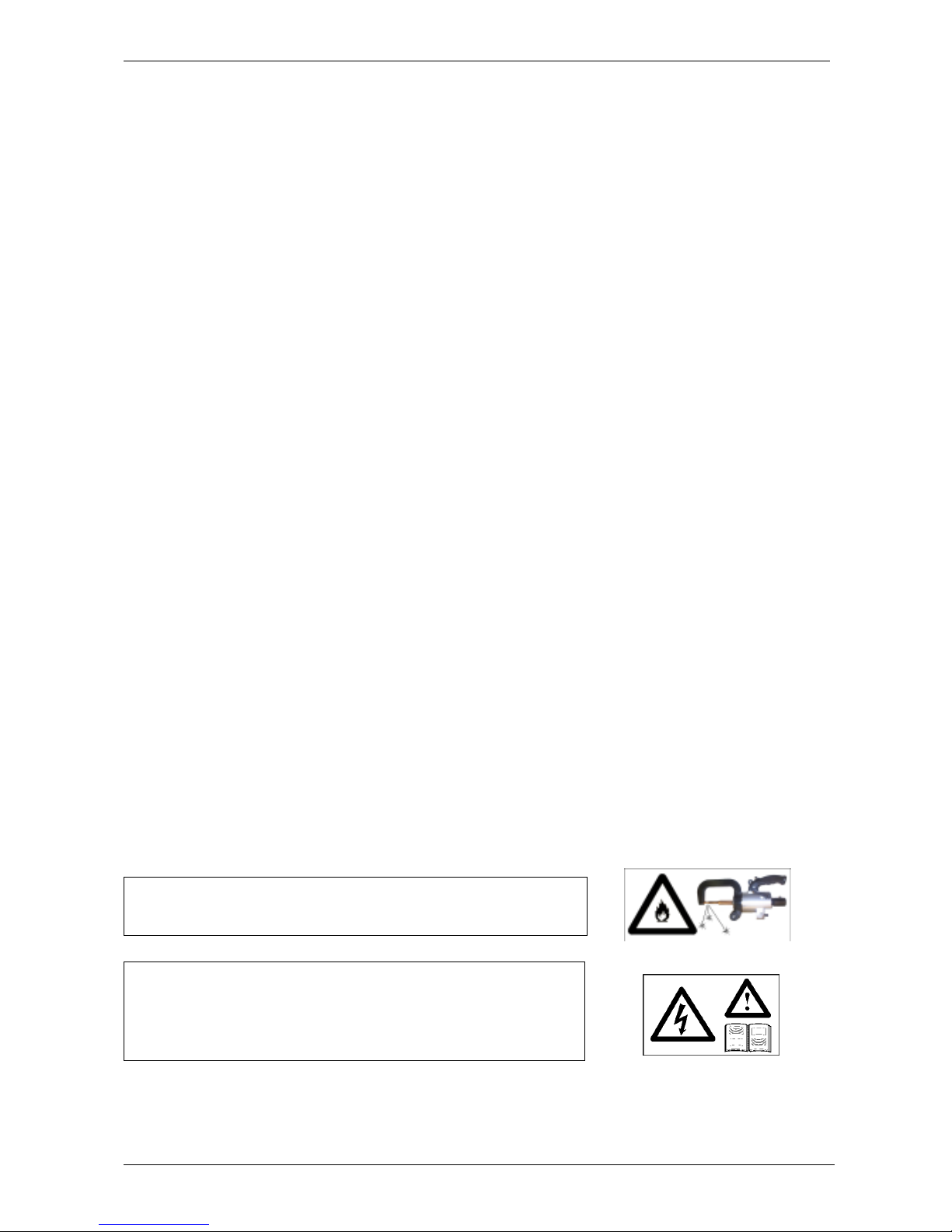
D5. Welding gun with single electrode (Operating Mode 4).
The use of a microprocessor in the BOSS+V4 means that the operator needs only set the
required value of the current before starting to use the equipment. However, some basic
welding rules need to be followed if best use is to be made of the machine:
- Do not weld on the body sheet to which the earth connection is made. (See section D4 on
the earth connection.)
- When performing spot welding, start with the spot furthest away from the earth
connection and work towards the earth connection.
- Make sure that the two body plates to be welded are in good metallic contact with each
other.
- Press the electrode against the body sheet by hand pressure. Note: Insufficient hand
pressure and too high a welding current can burn a hole in the metal and damage the
electrode. Make sure that you are using the correct combination of pressure and current.
- Wait for about a second after conclusion of welding before removing the gun, to allow time
for the weld to fuse.
- Reposition the welding gun and repeat the operation.
- Clean and sharpen the electrode tip carefully, particularly if poor contact has caused the
metal to stick to the tip of the electrode. (Probably due to excessive current and/or too low
hand pressure.)
- Let the machine and welding cables cool down if they overheat and/or if an overheating
alarm is generated.
Tong (Operating Mode 5-6).
The starting time of the welding cycle, a half second squeeze sequence, gives the possibility
to stop the cycle if bad positioning.
Important! Risk of damage to materials close to the weld,
e.g. glass or textiles.
Warning! All electrical work on the power unit (connection,
service and installation) must be performed only by authorized personnel. Disconnect the supply before performing
any service or installation work.
GB/US/2000-08 PRO SPOT
- 15 -
Page 17

Pro Spot PR-8
D. Operation
D6. Setting the welding current
The operator can increase or decrease the welding current with the + and – pushbuttons.
z The display (1) shows the Operating Mode and program that you have selected.
1.
Numbers 1 to 10 represents number of diodes ON.
Mode 4 (Diode 4 ON)
Prog Display (1) Anmärkning
1 31 0.5-0.6 mm Welding of 0.5 - 0.6 mm
2 32 0.6-0.7 mm Welding of 0.6 - 0.7 mm
3 33 0.7Weld into 1.5 Welding of 0.7 mot 1.5 mm
4 34 1.0Weld into 1.5 Welding of 1.0 into 1.5 mm
5 35 0.7Weld into 2.0 Welding of 0.7 into 2.0 mm
6 36 1.0Weld into 2.0 Welding of 1.0 into 2.0 mm
7 37 ACE3 0.5-0.7mm ACEnergy 3 for 0.5 - 0.7 mm welding
8 38 ACE5 0.7-1.0mm ACEnergy 5 for 0.7 - 1.0 mm welding
9 39 1.5Weld into 1.5 ACEnergy welding for 1.5 into 1.5 mm
10 40 1.5Weld into 2.0 ACEnergy welding for 1.5 into 2.0 mm
Mode 5 (Diode 5 ON)
1 41 STD PROG TWIN Sheet Thickness 0.5 - 0.7 mm
2 42 STD PROG TWIN Sheet Thickness 0.6 - 0.8 mm
3 43 STD PROG TWIN Sheet Thickness 0.7 - 0.9 mm
4 44 STD PROG TWIN Sheet Thickness 0.7 - 1.0 mm
5 45 STD PROG TWIN Sheet Thickness 1.0 - 1.4 mm
6 46 STD PROG TWIN Sheet Thickness 1.2 - 1.5 mm
7 47 STD PROG TWIN Sheet Thickness 1.6 - 2.0 mm
8 48 STD PROG TWIN Sheet Thickness 2.0 - 2.4 mm
9 49 STD PROG TWIN Sheet Thickness 2.2 - 2.5 mm
10 50 STD PROG TWIN Sheet Thickness 2.5 - 3.0 mm
Mode 6 (Diode 5 ON and Diod Extra Program ON)
1 51 0.7 - 0.7 GALV Welding of galvanized sheets 0.7 - 0.7 mm
2 52 1.0 - 1.0 GALV Welding of galvanized sheets 1.0 - 1.0 mm
3 53 1.5 - 1.5 GALV Welding of galvanized sheets 1.5 - 1.5 mm
4 54 2.0 - 2.0 GALV Welding of galvanized sheets 2.0 - 2.0 mm
5 55 AC1 0.5 - 1.9 AC1 Automatic program for sheets 0.5 to 1.9 mm (see D2)
6 56 AC2 1.0 - 3.0 AC2 Automatic program for sheets 1.0 to 3.0 mm (see D2)
7 57 ACE3 0.5 - 0.9 ACEnergy for sheets 0.5 - 0.9 mm
8 58 ACE7 0.7 - 1.4 ACEnergy for sheets 0.7 - 1.4 mm
9 59 ACE30 1.5 - 2.4 ACEnergy for sheets 1.5 - 2.4 mm
10 60 ACE50 2.5 - 3.0 ACEnergy for sheets 2.5 - 3.0 mm
GB/US/2000-08
- 16 -
PRO SPOT
Page 18

Pro Spot PR-8
E1. Welding problems
E. Trouble shooting
Swaging (Operating Mode 1):
Nothing happens when the graphite
electrode touches the body sheet:
- Make sure that the earth connection is
correctly positioned.
- Check the power supply to the machine
(fuses, MCBs, plugs inserted etc.).
- See the section on fault tracing.
Washer welding (Operating Mode 2)
Severe burning of the metal
- Reduce the current.
The edge of the washer penetrates into
the body sheet:
- Reduce the pressure on the washer and
reduce the current.
Stud welding (Operating Mode 3):
The studs do not hold:
- Make sure that the stud and the earth
contact are on the same body part.
- Position the earth connection close to the
part to be welded.
- Increase the pressure on the stud and
increase the current. Note: the current
and the pressure must be matched.
- Grind the sheet - it may be covered with
something that prevents proper current
flow.
Single electrode (Operating Mode 4)
Spot welds are not holding:
- Check the earth connection and make
sure that it is sufficiently close to the part
to be welded.
- Make sure that the earth connection is
secured to the supporting sheet and not to
the part to be welded.
- Start by welding the spot furthest away
from the earth connection and then work
towards the earth connection.
- Increase the pressure on the electrode,
and increase the current.
- Clean and sharpen the tip of the electrode.
- Check the power supply to the machine
(fuses, MCBs, plugs inserted etc.).
- Check that the welding cables are connected to the correct polarity (+ and –).
Double electrode (Operating Modes
5 and 6)
The electrode burns through the material:
- Replace the electrodes if they are too old.
- Check the air pressure: must be at least
6 bar.
Pressure for C-tong should be 5 bar(73
psi, see table on front panel).
- Check to see whether the electrode
clamping force is too low.
The studs burn through the sheet:
- Reduce the current.
- Increase the pressure on the stud.
- Grind the sheet for better current distribution.
GB/US/2000-08 PRO SPOT
- 17 -
Page 19

Pro Spot PR-8
E. Trouble shooting
E2. Error list
Error message (welding)
51 = Calculation error
53 = Measurement error
54 = Stop or thyristor fault
55 = Calibration error
56 = Too high power
57 = Resistance error (AC)
58 = Autoblanking not found (AC)
59 = Safety time (AC)
High temperature – Allow the machine to cool for a few minutes. Do not turn it off, so that the
fan can continue to run and the welding gun can work.
1.
2.
Press the V pushbutton and try again. If the
same error message recurs, stop using the
machine and call for service.
Error no. 5 will be displayed if you do not
press the V pushbutton.
1. Test button for the RCD (residual current
device). We recommend that you press this
button at least once a year to check that the
RCD is operating correctly.
3.
2. RCD. The machine incorporates an RCD
that protects against earth faults and power
failures. If it operates, reset it by turning it on
again.
3. MCB (miniature circuit-breaker). Protects
against overloads. If it operates, reset it by
turning it on again.
GB/US/2000-08
- 18 -
PRO SPOT
Page 20

Pro Spot PR-8
F. Technical specification
F1. Technical data
Permissible load : Duty cycle % 2.5% maximum load.
Supply voltage : 208 - 240 Volt, 60 A
: 400 - 440 Volt, 40 A
: 3 phase, 50/60 Hz
Output voltage : 15V
Welding current : 200-9500 A (see diagram)
Cable length : Up to 3 m (normally 3 m)
Welding cable area : 150 mm²
Cooling : Air + fan
No. of operating modes : 6
No. of programs : 60
Air supply pressure : 5 bar (C-tong), 6 - 8 bar (X-tong)
Degrees of protection : IP 23
Pro Spot PR-8 meets the following directives:
ETL and C-ETL Listed Mark, Low Voltage Directive LVD(73/23/EEC), The EMC Directive
(89/336/EEC), The Machinery Directive (89/392/EEC).
GB/US/2000-08 PRO SPOT
- 19 -
Page 21
Pro Spot PR-8
F. Technical specification
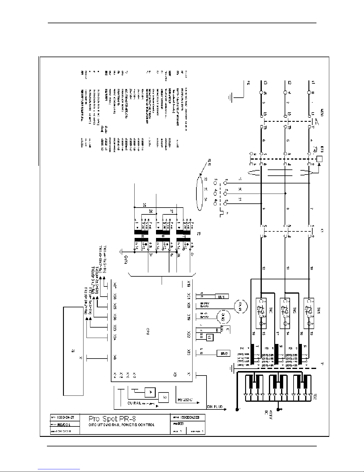
F2. Block diagram
Protect the equipment by means of an RCD where required by local regulations.
GB/US/2000-08
- 20 -
PRO SPOT
Page 22

Pro Spot PR-8
F3. Diagram
F. Technical specification
Welding current
15KA
10KA
5KA
01m2m3m
Mains voltage:
- High
- Medium
- Low
The actual welding current depends on
several factors: supply voltage, cable
length and cable cross-sectional area are
particularly important.
The diagram represents the main functions and processes graphically.
Cable length
15KA
10KA
5KA
300 mm²
240 mm²
150 mm²
01m2m3m
The power unit can supply a maximum of
18 kA. However, such a current is seldom
necessary, and it requires
a cable length
of zero.
For a welding current of 6-8 kA, which is a
normal value for 3+3 steel, 150 mm²
cables can be up to 2 m long. Heavier
currents require shorter or thicker cables.
(The diagram applies for a high mains
voltage and low internal impedance.)
Cable length
GB/US/2000-08 PRO SPOT
- 21 -
Page 23

Pro Spot PR-8
F. Technical specification
F3. Diagram (continued)
Intermittence factor
100 %
50 %
The intermittence factor is 100% for low
currents, and up to 60% for MIG/TIG
welding.
Spot welding is never performed continuously, which means that its intermittence
factor is probably 1-10% (0,6 seconds
welding with 6-10 seconds between welds).
The Pro Spot PR-8 has a intermittence
factor of: 2,5% without getting a overheat.
0 %
xxxxxxxxx
daN
150
100
50
xxxxxxxx
daN
Welding current
0 5 KA 10 KA 15 KA
150 300 450
Calculated as follow.
In 1 minute it’s possibly to make 8
spotwelds.
Each weld is 10 cycles = 200ms
Duty = (8 * 0,2)/(60-1,6) = 0,027 = 2,7%
xxxxxxxxxxxxxxxxxxxxxxx
250
200
100
100 200 300
GB/US/2000-08
xxxxxxxxxxxxxxxxxxxxxxxx
- 22 -
PRO SPOT
Page 24
Pro Spot PR-8
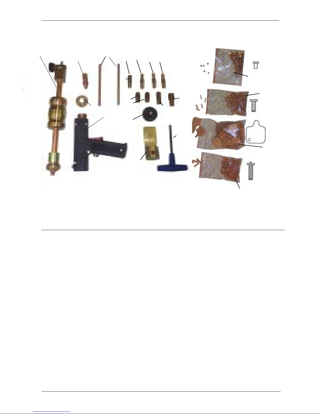
G. Spare parts
Grundsats/Basic set
1
4
3
6
2
5
12
19
7
18
89
11
10
17
x 200
15
13
x 100
x 50
16
x 50
14
Pos Part.No. Quant. Description
Basic set
1 1392001300 1 Puller
2 1394003201 1 Single spot gun
3 1391003101 1 Nut
4 1394001113 1 Electrode holder
5 1394001108 1 Pencil tip holder
6 1394001012 1 Graphite rod
7 1394001109 1 Stud holder diameter 5
8 1394001110 1 Stud holder diameter 6
9 1394001111 1 Rivet holder
10 1394001112 1 Stamp electrode
11 1394001116 1 Single-spot electrode (dome)
12 1394001103 2 Electrode length 40
13 1394001201 1 Stud, 5x14, coarse thread
14 1394001202 1 Stud, M6x20 (earth)
15 1394001204 1 Clip rivets
16 1394001207 1 Cover-plated washer
17 1394023001 1 Allen-key
18 1394010225 1 Grounding device
19 1394001011 1 Hand nut
GB/US/2000-08 PRO SPOT
- 23 -
Page 25

Pro Spot PR-8
G. Spare parts
3
54
14
2
1
6 7 8 9 10 11 12 13
22
21
20
19
15
17
16
Pos Part.No. Quant. Description
C-tong
1 1394025300 1 C-tong
2 1394025302 1 80-yoke
3 1394025303 1 330-yoke
4 1394001103 3 Electrode length 40
5 1394001101 1 Electrode length 80
1394025310 1 Fender Edge Kit
6 1394001135 1 Washer
7 1394001133 1 Electrode L80-S13
8 1394001134 1 Electrode L80/45°-S13
9 1394001132 1 Electrode L80/45°
10 1394001137 1 Electrodeholder
11 1394001136 1 Electrodeholder
12 1394001131 1 Electrode length 20
13 1394001104 1 Electrode -S
14 1394025304 1 Fender edge yoke
X-tong
15 1394023300 1 X-tong
16 1394023124 2 Arm L=150
17 1394001101 2 Electrode L=80
18 1394023101 2 Arm L=400
19 1394001101 6 Electrode L=80
20 1394001104 2 Electrode S
21 99200 1 Allen key 6mm
22 1394001127 1 Sleeve
GB/US/2000-08
- 24 -
18
PRO SPOT
Page 26

Pro Spot PR-8
1
G. Spare parts
2
14
13
Pos Part.No. Quant. Description
Cables
1 1394010306 1 Cable, 150mm
2 1394010305 1 Cable, 150mm
3 1394010306 1 Cable, 240mm
4 1394010305 1 Cable, 240mm
2
3m +
2
3m -
2
2,4m +
2
2,4m -
3
5
6
4
7
8 9 10 11 12
Electrodes
5 1394001131 1 Electrode length 20
6 1394001103 1 Electrode length 40
7 1394001102 1 Electrode length 60
8 1394001101 1 Electrode length 80
9 1394001128 1 Electrode length 100
10 1394001129 1 Electrode length 120
11 1394001130 1 Electrode length 140
12 1394001104 1 Electrode -S
Accessories
13 1394025201 1 Handle
14 1394025305 1 600-yoke
1394025311 1 600-yoke Kit
Pos. 14, 7, 10
GB/US/2000-08 PRO SPOT
- 25 -
Page 27
Pro Spot PR-8
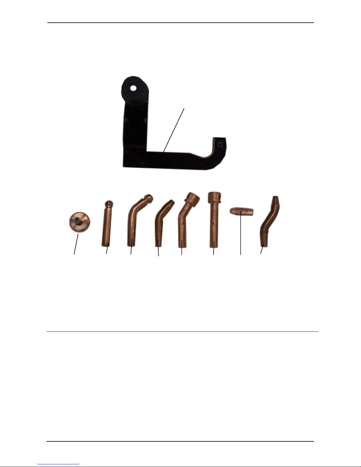
G. Spare parts
9
21
Pos Part.No. Quant. Description
1394025310 1 Fender Edge Kit
Accessories
1 1394001135 1 Washer
2 1394001133 1 Electrode L80-S13
3 1394001134 1 Electrode L80/45°-S13
4 1394001132 1 Electrode L80/45°
5 1394001137 1 Electrodeholder
6 1394001136 1 Electrodeholder
7 1394001131 1 Electrode length 20
8 1394001104 1 Electrode -S
9 1394025304 1 Fender edge yoke
3
4
5
6
7
8
GB/US/2000-08
- 26 -
PRO SPOT
Page 28

Pro Spot PR-8
H. C-tong Situations
GB/US/2000-08 PRO SPOT
- 27 -
Page 29

Pro Spot International, Inc
956 S. Andreasen Dr. #101
Escondido, CA 92029
U.S.A.
Tel 1-877 PRO SPOT
Fax (760) 489-1531
 Loading...