

Page 1
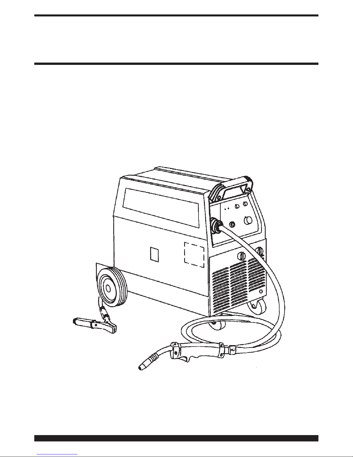
INSTRUCTION MANUAL FOR WIRE WELDING MACHINE
25/09/03
3.300.898
IMPORTANT OPERATING INSTRUCTIONS
SAVE THESE INSTRUCTIONS
Page 2
The additional letter C means that the
equipment is protected against access to
the live parts of the power supply circuit
by a tool (diameter 2.5 mm).
Suitable for use in high-risk environ-
ments.
NOTES: The welding machine has also been designed for
use in environments with a pollution rating of 3. (See IEC
664).
1.3 OVERLOAD CUT-OUT
This machine is protected by a thermostat, which prevents the machine from operating if the allowable temperatures are exceeded. In these conditions the fan continues to operate and the lamp Hlights.
2 DESCRIPTION OF THE MACHINE
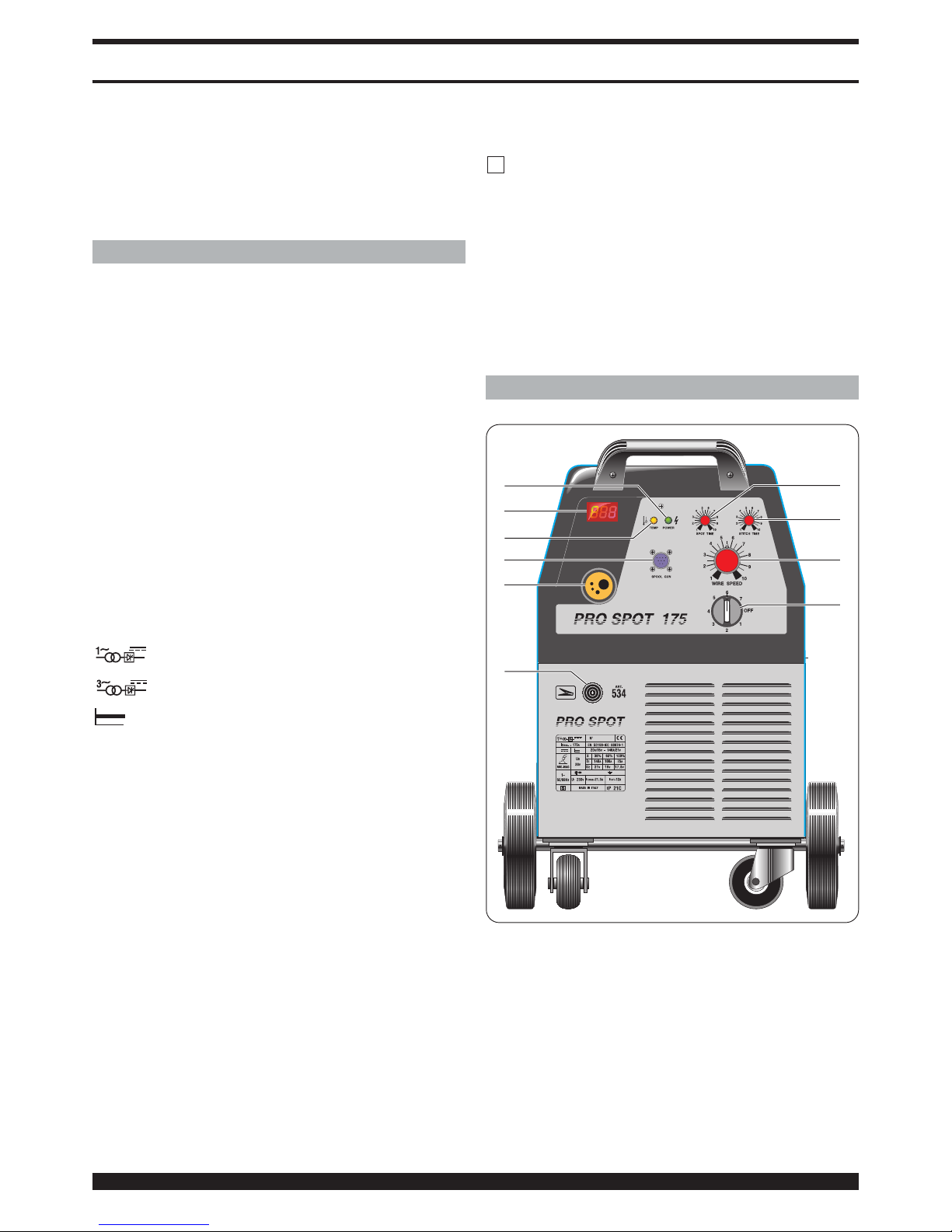
A) Selector switch.
Turns the machine on or off and select the welding
ranges.
B) Wire speed adjuster knob.
Use this knob to set the wire feed speed. This knob is
not active when the extension cable is connected to
the connector D
C) Spot time adjuster knob.
Use this knob to set the spot welding duration time.
When the button on the welding gun is pressed, the
machine will start spot welding and continue for the
time set on this knob. To start the next welding cycle,
release and press the welding torch button.
S
fig. 1
E
F
A
B
L
C
D
H
G
I
2
IMPORTANT: BEFORE STARTING THE EQUIPMENT,
READ THE CONTENTS OF THIS MANUAL, WHICH MUST
BE STORED IN A PLACE FAMILIAR TO ALL USERS FOR
THE ENTIRE OPERATIVE LIFE-SPAN OF THE MACHINE.
THIS EQUIPMENT MUST BE USED SOLELY FOR WELDING OPERATIONS.
FOR THE DIMENSIONS AND WEIGHT OF THIS WELDING
MACHINE, SEE THE SPECIFIC CATALOGUE.
1 GENERAL DESCRIPTION
1.1 SPECIFICATIONS
This manual has been prepared for the purpose of educating personnel assigned to install, operate and service
the welding machine.
This equipment is a constant-voltage power source, suitable for MIG/MAG and OPEN-ARC welding.
Upon receiving the machine, make sure there are no broken or damaged parts.
The purchaser should address any complaints for
losses or damage to the vector. Please indicate the
article and serial number whenever requesting information about the welding machine.
1.2 EXPLANATION OF TECHNICAL SPECIFICATIONS
EN 50199 The welding machine is manufactured
EN60974.1 according to these international stan-
dards.
N° serial number, which must always be
indicated on any type of request regarding the welding machine.
Single-phase transformer - rectifier
three-phase transformer-rectifier.
Flat characteristic.
MIG/MAG. Suitable for continuous electrode welding.
I2 max Unconventional welding current.
This value represents the max. limit
attainable in welding.
U0. Secondary open-circuit voltage.
X. Duty cycle percentage.
The duty cycle expresses the percentage
of 10 minutes during which the welding
machine may run at a certain current
without overheating.
I2. Welding current
U2. Secondary voltage with welding current
I2.
U1. Rated supply voltage
1~ 50/60Hz 50- or 60-Hz single-phase power supply.
3~ 50/60Hz 50- or 60-Hz three-phase power supply.
I1 max Maximum absorbed current value.
I1 eff This is the maximum value of the actual
current absorbed, considering the duty
cycle.
IP21C Protection rating for the housing.
Grade 1 as the second digit means that
this equipment is suitable for use out-
doors in the rain.
INSTRUCTION MANUAL FOR WIRE WELDING MACHINE
Page 3

3
D) Remote connector.
Connector for the extension cable.
E) Welding torch connector.
Connector for the welding torch (supplied) or the
extension cable.
F) Earth cable.
G) Ammeter.(optional)
The ammeter displays the welding current.
H) Yellow led.
This lights up when the thermostat interrupts welder
operation.
I) Green led.
This lights up when the selector switch (A) is on.
L) Rest time adjusting knob.
By means of this knob you can adyst the rest time
between a spot weld and the other. Such function is
active only when the spot time is on (knob C).
3 INSTALLATION
• Only skilled personnel should install the machine .
• All connections must be carried out according to
current regulations, and in full observance of safety
laws.
Make sure that the supply voltage corresponds to the
value indicated on the power cable. If it is not already fitted, connect a plug suited to the power cable, making
sure that the yellow/green conductor is connected to the
earth pin.
The capacity of the overload cutout switch or fuses
installed in series with the power supply must be equivalent to the absorbed current I1 max. of the machine.
Make sure that the wire diameter corresponds to the one
indicated on the roller, and mount the wire reel. Make sure
that the welding wire passes through the groove in the
small roller 2.
Before connecting the power cable 14, make sure that
the power voltage corresponds to that of the welding
machine, then:
a) for permanent connection to the power mains with-
out a plug, you must insert a main switch having a
suitable capacity in compliance with the rated specifications.
b) for a plug-socket connection, use a plug having a
suitable capacity in compliance with the rated specifications. In this case the plug must be used to
completely disconnect the machine from the mains,
after setting the switch A to “O” (off).
The yellow-green wire must be connected to the earth
terminal. Connect the earth clamp 24 to the part to be
welded.
The welding circuit must not be deliberately placed in
direct or indirect contact with the protection wire except
in the workpiece.
If the workpiece is deliberately grounded using the protection wire, the connection must be as direct as possible, using a wire at least as large as the welding current
return wire, and connected to the workpiece at the same
point as the return wire, using the return wire clamp or a
second grounding clamp placed next to it.
All precautions must be taken to avoid stray welding currents.
Turn the machine on using the switch A.
Remove the tapered gas tip by turning it clockwise.
Unscrew the contact tip.
Do not press the torch trigger until you have read the
instructions carefully.
It is important to make sure the machine is turned off
whenever changing the wire reel and wire roller, to prevent the wire feed motor from starting accidentally.
Press the torch trigger and release it only when the welding wire comes out.
welding wire can cause puncture wounds.
Never aim the torch at parts of the body, other people or
metals when loading the welding wire.
Screw the contact tip back on, making sure that the hole
diameter corresponds to the wire used.
Slide the tapered gas welding tip on, always turning
clockwise.
3.1 CYLINDER PLACEMENT AND CONNECTING
THE GAS HOSE
• Position the cylinder on the cylinder holder of the weld-
ing machine, using the straps provided to fasten it to the
rear panel of the machine.
• The gas cylinder must not be higher than 1m, to
avoid creating hazardous conditions.
• Periodically check for wear on the straps, and order
replacements if necessary.
• The cylinder must be equipped with a pressure regula-
tor complete with flow gauge.
• Only after positioning the cylinder, connect the outgoing
gas hose from the rear panel of the machine to the pressure regulator.
• Adjust the gas flow to approximately 10/12
liters/minute.
4 WELDING
4.1 SPOT WELDING
For spot welding, replace the gas-weld nozzle with the
special spot-weld nozzle. Exert enough pressure with the
torch to achieve a good junction of metal sheets.
This can be obtained by positioning the knob C on "spottime" and adjusting the spot-welding time through the
knob.
ATTENTION: Metal sheets will have to be perf
4.2 WELDING MILD STEEL
4.2.1 With gas protection.
Either 75% ARGON + 25% CO2 or 100% CO2 may be
used for welding mild steel.
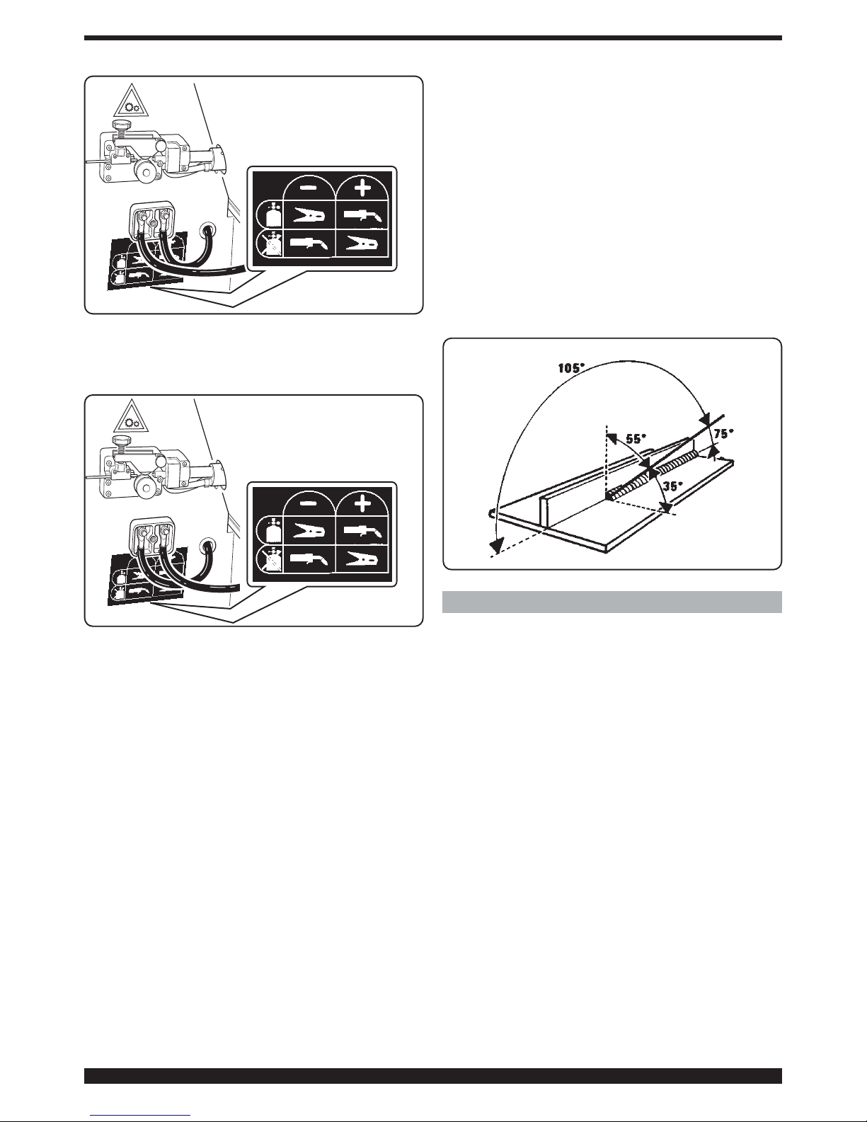
Connect the cables as shown in the figure 2.
Select the welding current by means of the rotary switchl
25. Move the torch near the welding point and press the
trigger.
Adjust the potentiometerl knob 31 until the welding is
done with a constant, continuous noise.
If the speed is too fast, the wire tends to stick to the piece
and cause the torch to skip; if the speed is too low, the
wire melts in spaced drops or the arc does not remain lit.
When you have finished welding, turn off the machine and
close the gas cylinder.
Page 4
4
For the correct welding angle see figure 4.
4.2.2 Without gas protection.
Connect the cables as shown in the figure 3.
Use only diam. 0.9-1.2mm flux cored wire that complies
with thestandard AWS AS.20 E71 TII or E71 TGS, suitable
for use without gaseous protection.
Connect the earth cable clamp to the workpiece. After
connecting the cables, follow the instructions given in
paragraph 5.2.1.
NOTE: For compact, well-protected welds always work
from left to right and from top to bottom.
Remove all waste after each welding operation.
For the correct welding angle see figure 4.
4.3 WELDING ALUMINIUM
The welding machine must be prepared as for welding
mild steel with gas protection, but with the following differences:
- 100% ARGON as the protection gas for welding.
- A wire having a composition suited to the base material
to be welded.
For welding ALLUMAN: 3÷5% silicon wire
- For welding ANTICORODAL: 3÷5% silicon wire
- For welding PERALUMAN: 5% magnesium wire
- For welding ERGAL: 5% magnesium wire
Use abrasive grinders and tool brushes specifically
designed for aluminium. Never use these tools on other
materials.
REMEMBER that cleanliness equals quality.
The wire spools must be stored in plastic bags with a
dehumidifier.
See the figure for correct torch inclination.
4.4 WELDING STAINLESS STEEL.
The welding machine must be prepared as for welding
mild steel with gas protection, but with the following differences:
- Reel of stainless steel wire compatible with the compo-
sition of the material to be welded.
- Cylinder containing 98% ARGON + 2% 02 (recom-
mended composition)
The recommended torch angle and welding direction are
shown in figure 4.
5 MAINTENANCE AND CHECKS.
5.1 GENERAL NOTES.
· Turn off the welding machine and unplug the power
cord from the socket before each checking and maintenance operation.
· Moving parts can cause serious lesions
· Keep away from moving parts.
· INCANDESCENT SURFACES can cause serious burns.
· Let the unit cool before servicing.
· Periodically remove any dust or foreign matter that may
have deposited on the transformer or diodes; to do so,
use a jet of clean, dry air.
· When replacing the wire roller, make sure the groove is
aligned with the wire and corresponds to the diameter of
the wire used.
· Always keep the interior of the gas nozzle clean to avoid
metal bridges created by welding dross between the gas
nozzle and the contact tip. Make sure the outlet hole of
the contact tip has not expanded excessively; if so,
replace.
· Strictly avoid striking the torch or allowing it to suffer
violent impact.
5.2 REPAIRING THE WELDING MACHINE.
Experience has shown that many accidents are caused
by repairs performed incorrectly. That is why it is just as
fig. 2
fig. 3
fig. 4
Page 5
· If the repairs have not been performed by the manufac-
turer, repaired welding machines in which some components have been replaced or altered must be marked in
such a way that the person who performed the repairs is
clearly identifiable.
·
After making repairs, take care to re-order the wiring so
that there is certain insulation between the primary side
and the secondary side of the machine. Prevent the wires
from coming into contact with moving parts or parts that
heat up during operation. Replace all clamps as on the
original machine to prevent a connection from occurring
between the primary and secondary side if a conductor
accidentally breaks or disconnects.
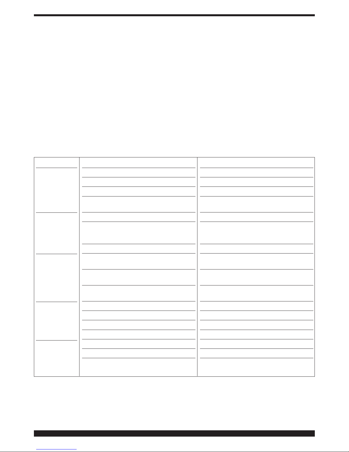
5.3 TROUBLESHOOTING GUIDE.
5
important to check a repaired welding machine carefully
and completely as it is for a new welding machine.
In addition, this protects the manufacturer from being
held liable for defects when the true fault lies elsewhere.
5.2.1 Instructions for performing repairs
· After rewinding the transformer or inductance, the weld-
ing machine must pass the applied voltage tests as indicated in table 2 of paragraph 6.1.3 of the standard EN
60974.1 (CEI 26.13). Compliance must be verified as
specified in 6.1.3.
· If no rewinding has been done, a welding machine that
has been cleaned and/or revised must pass an applied
voltage test with test voltage values equal to 50% of the
values given in table 2 of paragraph 6.1.3. Compliance
must be verified as specified in 6.1.3.
· After rewinding and/or replacing parts, the no-load volt-
age must not exceed the values given in paragraph 10.1
of EN 60974.1.
TROUBLE
The welding
machine supplies limited
current.
Welding with a
lot of metal
spatter
The wire jams or
entangles
between the
drive rolls and
the torch infeed
wire guide
No wire feed or
irregular wire
feed
Porosity in the
welding seam
PROBABLE CAUSE
Line fuse blown
Burnt out diode or diodes
Burnt out electronic board
Loosened torch or earth connections or any
other electrical power connections
Voltage adjustment switch has a loose contact
Improper adjustment of welding parameters
Insufficient grounding
Contact tip with wrong diameter
Misalignment of the drive roll groove
Obstructed or clogged liner
Drive roll with too large a groove
Obstructed or clogged liner
Wire holding roller not completely tightened
Clogged contact tip
Insufficient shielding gas
Excess oxidation of the edges to be welded.
Gas nozzle partially or completely clogged by
spatter
REMEDY
Replace line fuse
Replace
Replace
Tighten all connections
Replace the switch
Select the correct parame- ters through the
welding-voltage switch and the wire-speed
adjustment poten-tiometer
Check grounding connections
Replace
Realign
Remove and clean
Replace the drive roll
Remove and clean
Tighten all the way
Replace
Increase gas delivery.
Thoroughly clean the edges with a metal brush
Remove and clean or replace being careful not
to clog the gas outlets
Page 6
6
6 SAFETY PRECAUTIONS
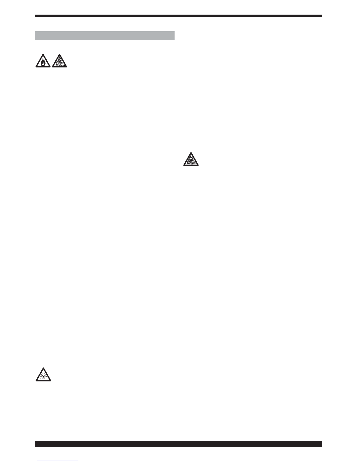
6.1 Fire
·
Avoid causing fire because of sparks,
slag, hot metal or pieces.
·
Make sure that suitable fire-fighting
equipment is available close to welding area.
·
Remove all flammable and combustible material from
the welding area and its surrounding (32 ft minimum).
·
Do not weld containers of combustible or flammable
material, even when empty. These must be carefully
cleaned before being welded.
·
Allow the welded material to cool down before touching
it or putting it in contact with combustible or flammable
material.
·
Do not weld parts with hollow spaces, containing flammables.
·
Do not work under conditions with high concentrations
of combustible vapours, gases, or flammable dust.
·
Always check the work area half an hour after welding
so as to make sure that no fire has started.
·
Do not keep any combustible material such as lighters
or matches in your pockets.
6.2 Burns
·
Wear fire-proof clothing all over your body in order to
protect your skin against burns caused by ultraviolet radiation given off by the arc, and from weld metal sparks and
slag.
·
Wear protective clothing-gauntlet gloves designed for
use in welding, hat and high safety-toe shoes. Button
shirt collar and pocket flaps, and wear cuff-less trousers
to avoid entry of sparks and slag.
·
Wear helmet with safety goggles and glasses with side
shields underneath, appropriate filter lenses or plates
(protected by clear cover glass). This is a MUST for welding to protect the eyes from radiant energy and flying
metal. Replace cover glass when broken, pitted, or spattered.
·
Avoid oil or greasy clothing. A spark may ignite them.
Hot metal such as electrode stubs and workpieces
should never be handled without gloves.
·
First-aid facilities and a qualified first-aid person should
be available for each shift unless medical facilities are
close by for immediate treatment of flash burns of the
eyes and skin burns.
·
Ear plugs should be worn when working on overhead or
in a confined space. A hard hat should be worn when others work overhead.
·
Flammable hair preparations should not be used by
persons intending to weld or cut.
6.3 Fumes
Welding operations give off harmful fumes and
metal dusts which may be hazardous to your
health, therefore:
·
Work in a well-ventilated area.
·
Keep your head out of fumes.
·
In closed areas, use suitable exhaust fans.
·
If ventilation is not enough, use breathing sets approved
for this procedure.
·
Clean the material to be welded of any solvents or halogen degreasers giving rise to toxic gases. Some clorine
solvents may decompose with the radiation emitted by
the arc, and create phosgene gas.
·
Do not weld plated metals or those containing lead,
graphite, cadmium, zink, chrome, mercury or beryllium,
unless you have the proper breathing set.
·
The electric arc creates ozone. A long exposure to high
concentrations may cause headaches, nasal, throat and
eye irritation as well as serious congestions and chest
pains.
IMPORTANT: DO NOT USE OXYGEN FOR VENTILATION.
·
Gas leaks in a confined space should be avoided.
Leaked gas in large quantities can change oxygen concentration dangerously. Do not bring gas cylinders into a
confined space.
·
DO NOT WELD where solvent vapors can be drawn into
the welding atmosphere or where the radiant energy can
penetrate to atmospheres containing even minute
amounts of trichloroethylene or perchloroethylene.
6.4 Explosions
Do not weld above or near containers under pressure.
·
Do not weld in environments containing explosive dusts, gases or vapours.
This welding machine uses inert gases such as CO2,
ARGON, or a mixture of ARGON + CO2 for the protection
of the arc, thus you should take special precautions:
A) CYLINDERS
·
Do not directly connect cylinder to the machine gas
hose without a pressure regulator.
·
Handle or use pressure cylinders in conformity with the
existing rules.
·
Do not use leaking or damaged cylinders.
·
Do not use cylinders which are not well secured.
·
Do not carry cylinders without the protection of the
installed valve.
·
Do not use cylinders whose content has not been clear-
ly identified.
·
Never lubricate cylinder valves with oil or grease.
·
Do not put the cylinder in electrical contact with the arc.
·
Do not expose cylinders to excessive heat, sparks,
molten slags or flame.
·
Do not tamper with the cylinder valves.
·
Do not try to loosen tight valves by means of hammers,
keys, or any other object.
·
NEVER DEFACE or alter name, number, or other mark-
ings on a cylinder. It is illegal and hazardous.
·
Do not lift cylinders off the ground by their valves or
caps, or by chains, slings or magnets.
·
Never try to mix any gases in a cylinder.
·
Never refill any cylinder.
·
Cylinder fittings should never be modified or exchanged.
B) PRESSURE REGULATORS
·
Keep pressure regulators in good condition. Damaged
regulators may cause damages or accidents, they should
only be repaired by skilled personnel.
·
Do not use regulators for gases other than those for
which they are manufactured.
·
Never use a leaking or damaged regulator.
·
Never lubricate regulators with oil or grease.
C) HOSES
·
Replace hoses which appear damaged.
Page 7
7
·
Keep hoses unwound in order to avoid bending.
·
Keep the excess hose wound and out of the working
area in order to avoid any damage.
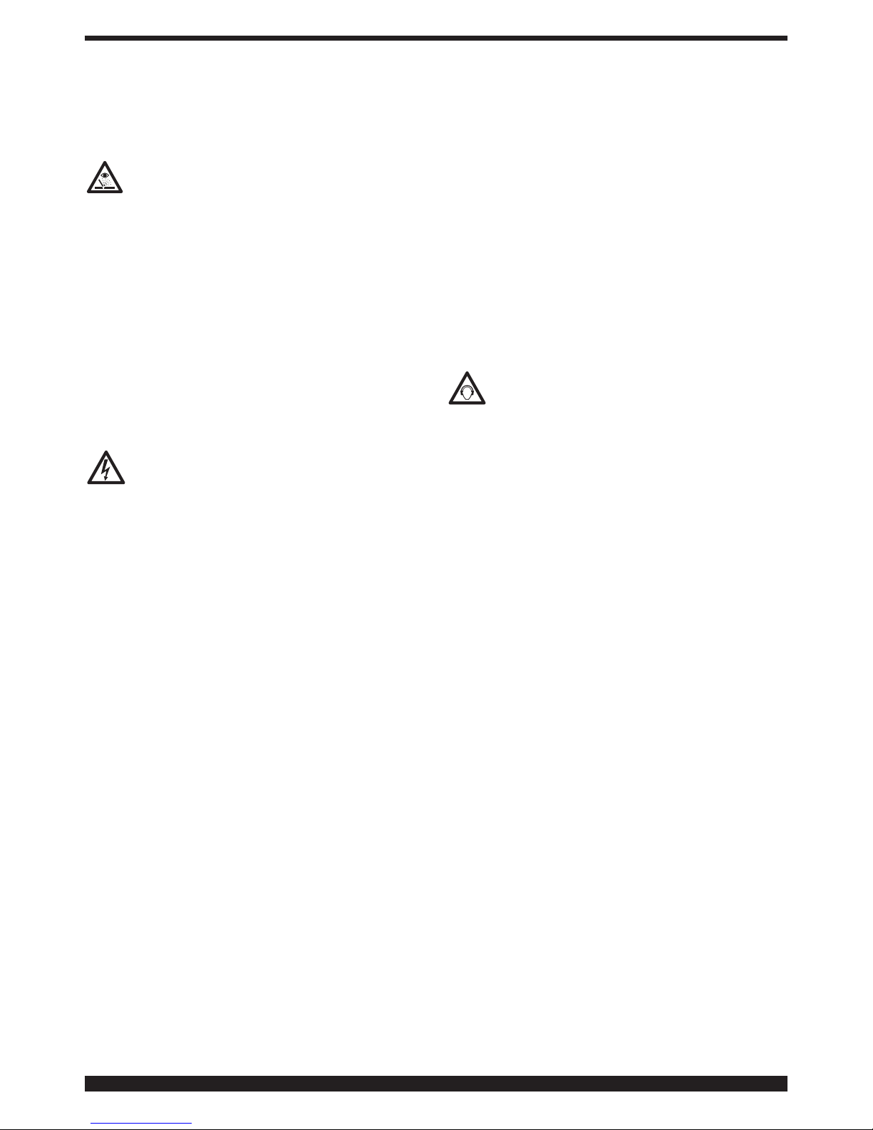
6.5 Radiations
Ultra-violet radiation created by the arc may
damage your eyes and burn your skin. Therefore:
·
Wear proper clothing and helmet.
·
Do not use contact lenses!! The intense heat coming
from the arc may cause them to stick to the cornea.
·
Use masks with grade DIN 10 or DIN 11 safety lenses
at the least.
·
Protect people in the surrounding welding area.
Remember: the arc may dazzle or damage the eyes. It is
considered dangerous up to a distance of 15 meters (50
feet). Never look at the arc with the naked eye.
·
Prepare the welding area so as to reduce reflection and
transmission of ultra-violet radiation. Paint walls and
exposed surfaces in black to reduce reflection, install
sheathings or curtains to reduce ultra-violet transmissions.
·
Replace mask lenses whenever damaged or broken.
6.6 Electric shock
Electric shock can kill.
All electric shocks are potentially fatal.
·
Do not touch live parts.
·
Insulate yourself from the piece to be cut and from the
ground by wearing insulated gloves and clothing.
·
Keep garments (gloves, shoes, hats, clothing) and body
dry.
·
Do not work in humid or wet areas.
·
Avoid touching the piece to be welded.
·
Should you work close to or in a dangerous area, use all
possible precautions.
·
If you should feel even the slightest electric shock sensation, stop welding immediately. Do not use the machine
until the problem is identified and solved.
·
Always fit an automatic wall switch with adequate
power, possibly close to the machine, allowing you to
immediately switch the machine off in case of an emergency.
·
Frequently inspect the power supply cable.
·
Disconnect power supply cable from mains before
replacing cables or before removing unit covers.
·
Do not use the unit without protection covers.
·
Always replace any damaged parts of the unit, with
original material.
·
Never disconnect unit safety devices.
·
Make sure that the power supply line is equipped with
an efficient earth plug.
·
Any maintenance should only be carried out by qualified
personnel aware of the risks due to dangerous voltages
necessary for the operation of the unit.
6.7 Pace maker
·
Magnetic fields from high currents can affect pacemaker operation. Persons wearing electronic life support
equipment (pacemaker) should consult their doctor
before going near arc welding, gouging or spot welding
operations.
6.8. Caution!
Welding wire can cause puncture wounds.
·
Do not press gun trigger until instructed to do so.
·
Do not point gun toward any part of the body, other
people, or any metal when threading welding wire.
6.9. Moving parts can cause injury.
Moving parts, such as fans, can cut fingers and hands
and catch loose clothing.
·
Keep all doors, panels, covers, and guards closed and
securely in place.
·
Have only qualified people remove guards or covers for
maintenance and troubleshooting as necessary.
·
Keep hands, hair, loose clothing, and tools away from
moving parts.
·
Reinstall panels or guards and close doors when ser-
vicing is finished and before starting the machine.
6.10 Noise
These power source alone do not produce noise
levels exceeding 80 dB. The welding procedure,
however, may produce noise levels in excess of 80
dB. in which case the machine operator must take the
necessary safety precautions as prescribed by the national safety regulation.
Page 8
8
Page 9
9
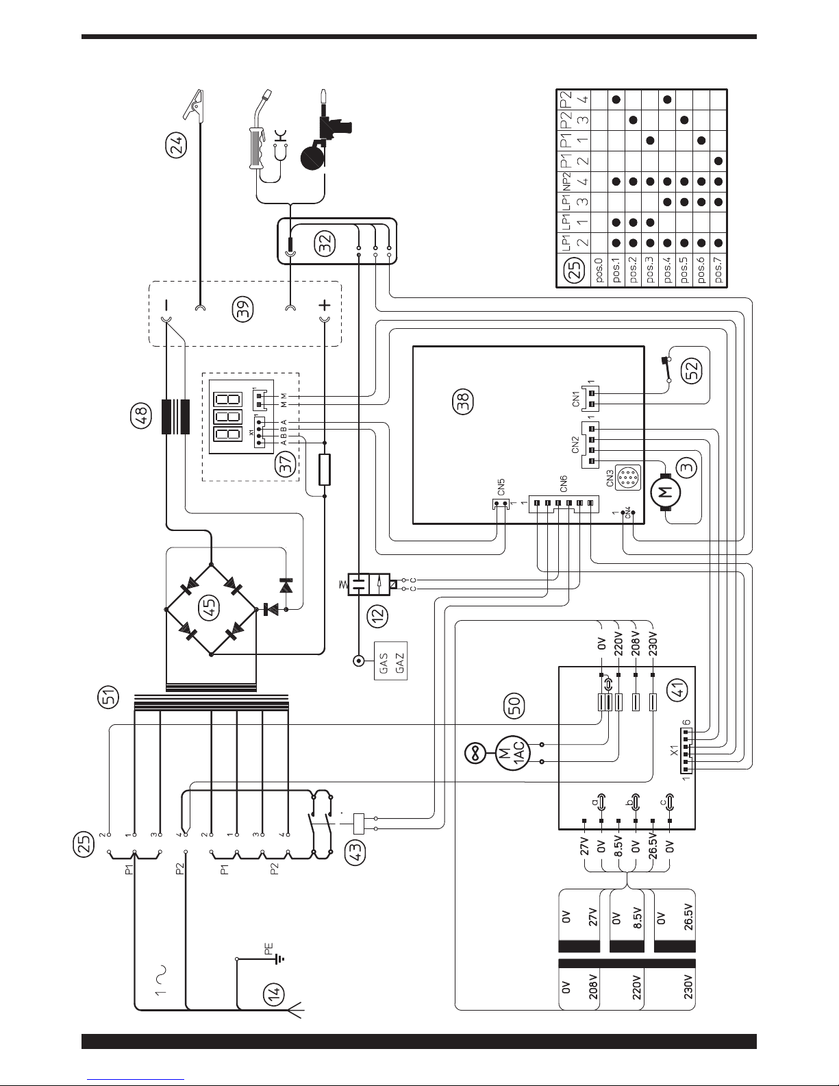
WIRING DIAGRAM COLOUR CODE
A BLACK
B RED
C GREY
D WHITE
E GREEN
F PURPLE
G YELLOW
H BLUE
K BROWN
J AORANGE
I PINK
L PINK-BLACK
M GREY-PURPLE
N WHITE-PURPLE
O WHITE-BLACK
P GREY-BLUE
Q WHITE-RED
R GREY-RED
S WHITE-BLUE
T BLACK-BLUE
U YELLOW-GREEN
V BLUE
Page 10
10
8
11
14
9
47
9
13
12
10
40
43
44
45
15
46
4
41
42
50
49
20
15
52
39
38
25
19
18
17
1648512223
21
2426272829
34
32
31
33
30
37
36
2
3
1
35
5 6 7
Page 11
11
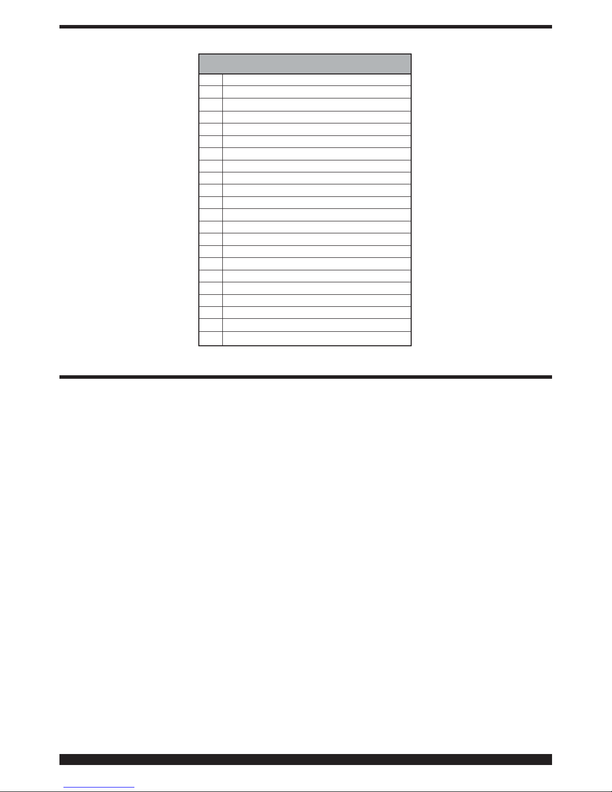
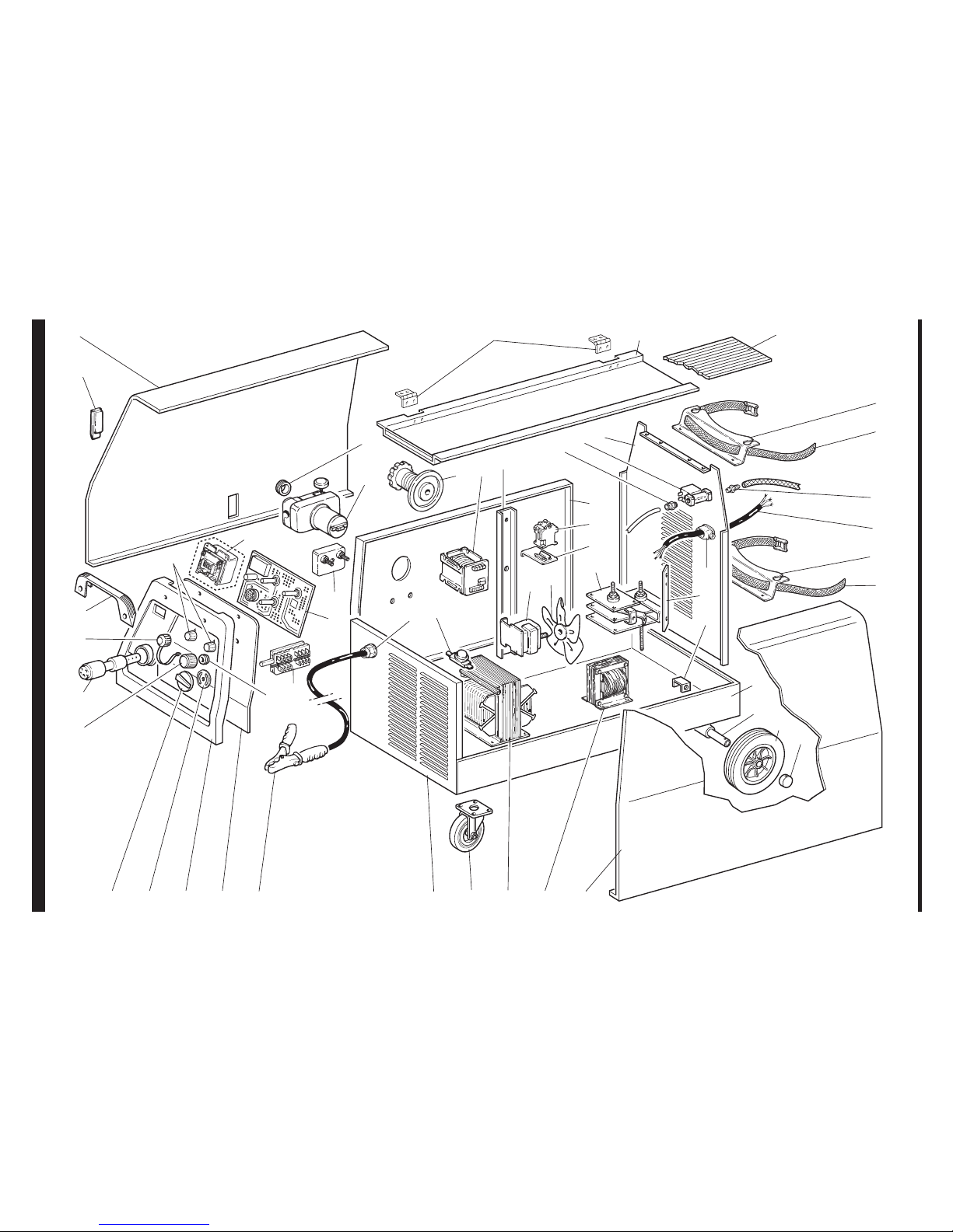
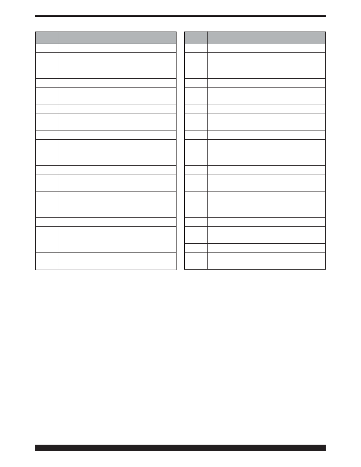
When ordering spare parts please always state the machine item and serial number and its purchase data, the spare
part position and the quantity.
01 HINGED SIDE PANEL
02 WIRE FEED ROLLER
03 WIRE FEED MOTOR
04 COIL SUPPORT
05 HINGE
06 COVER
07 RUBBER MAT
08 GAS CYLINDER SUPPORT
09 BELT
10 BACK PANEL
11 FITTING
12 SOLENOID VALVE
13 FITTING
14 POWER CORD
15 STRAIN RELIEF
16 FIXED SIDE PANEL
17 CAP
18 FIXED WHEEL
19 AXLE
20 SUPPORT
21 BOTTOM
22 SWIVELING WHEEL
23 FRONT PANEL
24 EARTH CABLE
25 SWITCH
26 CONTROL PANEL
27 FRAME
28 RUBBER PROTECTION
29 KNOB
30 RUBBER PROTECTION
31 KNOB
32 ADAPTOR BODY
33 CAP
34 HANDLE
35 CLOSING
36 KNOB
37 AMPERMETER
38 CIRCUIT BOARD
39 TERMINAL BOARD
40 INSIDE BAFFLE
41 AUXLIARY TRANSFORMER
42 SUPPORT
43 CONTACTOR
44 SUPPORT
45 RECTIFIER
46 SHUNT
47 GAS CYLINDER SUPPORT
48 CHOKE
49 FAN
50 MOTOR
51 TRANSFORMER
52 THERMOSTAT
pos DESCRIPTIONpos DESCRIPTION
Page 12

12
 Loading...