

Page 1
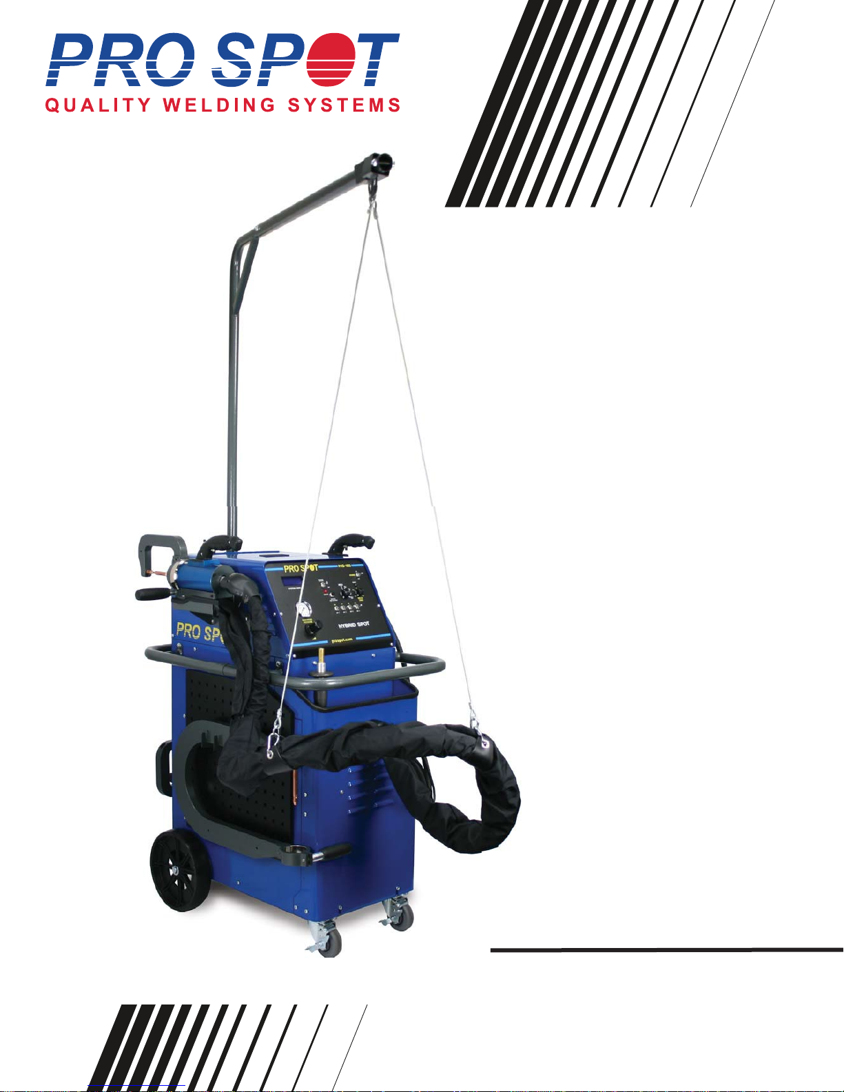
Hybrid Spot
Battery Powered
Resistance Spot Welder
Instruction Manual
Version 1.7
All Info Copyright © Pro Spot International Inc.
Page 2

Hybrid Spot
Table Of Contents
Quick start instructions . . . . . . . . . . . . . . . . . . . . . . . . . . . . . . . . . . . . . .4
1 Introduction . . . . . . . . . . . . . . . . . . . . . . . . . . . . . . . . . . . . . . . . . . . . . 5
2 Safety
2.0 Safety & Environmental Specifications. . . . . . . . . . . . . . . . . . . . . . . . . . . . . . . . . . . .6
2.1 General . . . . . . . . . . . . . . . . . . . . . . . . . . . . . . . . . . . . . . . . . . . . . . . . . . . . . . . . . . .6
2.2 Warnings and important notices . . . . . . . . . . . . . . . . . . . . . . . . . . . . . . . . . . . . . . . .6
2.3 Safety devices . . . . . . . . . . . . . . . . . . . . . . . . . . . . . . . . . . . . . . . . . . . . . . . . . . . . . .8
2.3.1 Cooling . . . . . . . . . . . . . . . . . . . . . . . . . . . . . . . . . . . . . . . . . . . . . . . . . . . . . .8
3 Installation
3.1 General . . . . . . . . . . . . . . . . . . . . . . . . . . . . . . . . . . . . . . . . . . . . . . . . . . . . . . . . . . .9
3.2 Packaging and delivery inspection . . . . . . . . . . . . . . . . . . . . . . . . . . . . . . . . . . . . . .9
3.3 Welder assembly . . . . . . . . . . . . . . . . . . . . . . . . . . . . . . . . . . . . . . . . . . . . . . . . . . .9
3.4 Battery Installation . . . . . . . . . . . . . . . . . . . . . . . . . . . . . . . . . . . . . . . . . . . . . . . . . . .10
3.5 Connection of electrical supply . . . . . . . . . . . . . . . . . . . . . . . . . . . . . . . . . . . . . . . . .11
3.6 Connection of pneumatic air supply . . . . . . . . . . . . . . . . . . . . . . . . . . . . . . . . . . . . .11
4 Operation
4.1 Before you begin welding . . . . . . . . . . . . . . . . . . . . . . . . . . . . . . . . . . . . . . . . . . . .12
4.2 About your welder . . . . . . . . . . . . . . . . . . . . . . . . . . . . . . . . . . . . . . . . . . . . . . . . . .13
4.2.1 Welder Overview & Technical Specifications . . . . . . . . . . . . . . . . . . . . . . . . 13
4.2.2 Getting familiar with your welder . . . . . . . . . . . . . . . . . . . . . . . . . . . . . . . . . .13
4.2.3 Control Panel . . . . . . . . . . . . . . . . . . . . . . . . . . . . . . . . . . . . . . . . . . . . . . . . .14
4.2.4 Indications on the Control Panel . . . . . . . . . . . . . . . . . . . . . . . . . . . . . . . . . .14
4.3 Turning on the welder . . . . . . . . . . . . . . . . . . . . . . . . . . . . . . . . . . . . . . . . . . . . . . .14
4.3.1 Checking & Charging battery voltage. . . . . . . . . . . . . . . . . . . . . . . . . . . . . . . . 15
4.3.2 Battery Alerts. . . . . . . . . . . . . . . . . . . . . . . . . . . . . . . . . . . . . . . . . . . . . . . . . . . .15
4.3.3 Removing Battery Covers for Service. . . . . . . . . . . . . . . . . . . . . . . . . . . . . . . . .16
4.3.4 Checking Battery Water Levels . . . . . . . . . . . . . . . . . . . . . . . . . . . . . . . . . . . . . .16
4.4 Choosing the weld mode . . . . . . . . . . . . . . . . . . . . . . . . . . . . . . . . . . . . . . . . . . . .17
4.5 Setting the pneumatic air pressure . . . . . . . . . . . . . . . . . . . . . . . . . . . . . . . . . . . . .17
4.6 Setting/Changing the weld program . . . . . . . . . . . . . . . . .
4.7 Setting the weld time . . . . . . . . . . . . . . . . . . . . . . . . . . . . . . . . . . . . . . . . . . . . . . .17
4.8 Checking weld quality. . . . . . . . . . . . . . . . . . . . . . . . . . . . . . . . . . . . . . . . . . . . . . . .18
5 Double-Sided Welding
5.1 PS-500 Double-Acting Spot Gun . . . . . . . . . . . . . . . . . . . . . . . . . . . . . . . . . . . . . .19
5.1.1 PS-500 Component Diagram . . . . . . . . . . . . . . . . . . . . . . . . . . . . . . . . . . . .19
5.1.2 Using the Double-Acting Gun . . . . . . . . . . . . . . . . . . . . . . . . . . . . . . . . . . . .19
5.2 Extension Arms . . . . . . . . . . . . . . . . . . . . . . . . . . . . . . . . . . . . . . . . . . . . . . . . . . . .19
5.2.1 Switching to extension arms . . . . . . . . . . . . . . . . . . . . . . . . . . . . . . . . . . . . .20
5.2.2 Extension Arms and Welding Electrodes . . . . . . . . . . . . . . . . . . . . . . . . . . .21
5.3 PS-500 Electrode Alignment . . . . . . . . . . . . . . . . . . . . . . . . . . . . . . . . . . . . . . . . . .22
5.4 Removing Welding Electrodes . . . . . . . . . . . . . . . . . . . . . . . . . . . . . . . . . . . . . . . .23
5.5 Welding Electrode Maintenance . . . . . . . . . . . . . . . . . . . . . . . . . . . . . . . . . . . . . . .24
. . . . . . . . . . . . . . . . . . .17
All Info Copyright © Pro Spot International Inc.
Page 3
Hybrid Spot
Table Of Contents
5.6 Wheel House Arm . . . . . . . . . . . . . . . . . . . . . . . . . . . . . . . . . . . . . . . . . . . . . . . . . .24
5.7 X-Adapter (optional) . . . . . . . . . . . . . . . . . . . . . . . . . . . . . . . . . . . . . . . . . . . . . . . .25
5.7.1 Attaching the X-Adapter . . . . . . . . . . . . . . . . . . . . . . . . . . . . . . . . . . . . . . . .25
5.7.2 Using the X-Adapter . . . . . . . . . . . . . . . . . . . . . . . . . . . . . . . . . . . . . . . . . . .26
5.7.3 X-Adapter Configurations . . . . . . . . . . . . . . . . . . . . . . . . . . . . . . . . . . . . . . .26
6 Single-Sided Welding
6.1 Single-Sided Welding Overview . . . . . . . . . . . . . . . . . . . . . . . . . . . . . . . . . . . . . . .27-28
6.2 Single-Sided Spot Welding . . . . . . . . . . . . . . . . . . . . . . . . . . . . . . . . . . . . . . . . . . .29
6.3 Bolt Welding . . . . . . . . . . . . . . . . . . . . . . . . . . . . . . . . . . . . . . . . . . . . . . . . . . . . . . .29
6.4 Nut Welding . . . . . . . . . . . . . . . . . . . . . . . . . . . . . . . . . . . . . . . . . . . . . . . . . . . . . . .30
6.5 Dent Pulling with Spot Hammer . . . . . . . . . . . . . . . . . . . . . . . . . . . . . . . . . . . . . . . .30
6.6 Moulding Clip Rivet Welding . . . . . . . . . . . . . . . . . . . . . . . . . . . . . . . . . . . . . . . . . .31
6.7 Dent Pulling with Washers and Slide Hammer with Hook . . . . . . . . . . . . . . . . . . . .31
6.8 Contact Shrinking . . . . . . . . . . . . . . . . . . . . . . . . . . . . . . . . . . . . . . . . . . . . . . . . . .32
6.9 Pro Pull Dent Pulling (optional) . . . . . . . . . . . . . . . . . . . . . . . . . . . . . . . . . . . . . . . .33
6.9.1 Selecting Pro Pull Weld Mode . . . . . . . . . . . . . . . . . . . . . . . . . . . . . . . . . . . .33
6.9.2 Pro Pull Component Diagram . . . . . . . . . . . . . . . . . . . . . . . . . . . . . . . . . . . .33
6.9.3 Pro Pull Assembly . . . . . . . . . . . . . . . . . . . . . . . . . . . . . . . . . . . . . . . . . . . . .34
6.9.4 Dent Pulling with Pro Pull . . . . . . . . . . . . . . . . . . . . . . . . . . . . . . . . . . . . . . .34
6.9.5 Paintless Dent Pulling With Pro Pull . . . . . . . . . . . . . . . . . . . . . . . . . . . . . . .34
7 Troubleshooting
Troubleshooting . . . . . . . . . . . . . . . . . . . . . . . . . . . . . . . . . . . . . . . . . . . . . . . . . . . .35
OPEN CIRCUIT VOLTAGE AS IT RELATES TO STATE OF CHARGE
Open Circuit Voltage* State of Charge
12.80 or greater.............................100%
12.60..................................75%
12.30..................................50%
12.00..................................25%
12.00....................................0
* The actual stabilized OCV can only be determined after the
battery has been disconnected from the charger for 24 hours.
READ BEFORE OPERATING WELDER!
Connect all 4 cables to negative
battery terminals Before using.
To access terminals, open right
side cover.
(The four cables to the negative battery terminals are
disconnected during shipping.)
Battery Warnings
DANGER/POISON
SHIELD
EYES.
EXPLOSIVE
GASES CAN
CAUSE BLINDNESS
OR INJURY.
KEEP OUT OF REACH OF CHILDREN
NO
SPARKS
FLAMES
SMOKING
SULFURIC
ACID
CAN
CAUSE
BLINDNESS OR
SEVERE BURNS.
FLUSH EYES
IMMEDIATELY
WITH WATER.
HELP FAST.
GET
MEDICAL
All Info Copyright © Pro Spot International Inc.
Page 2
3
Page 4
Hybrid Spot
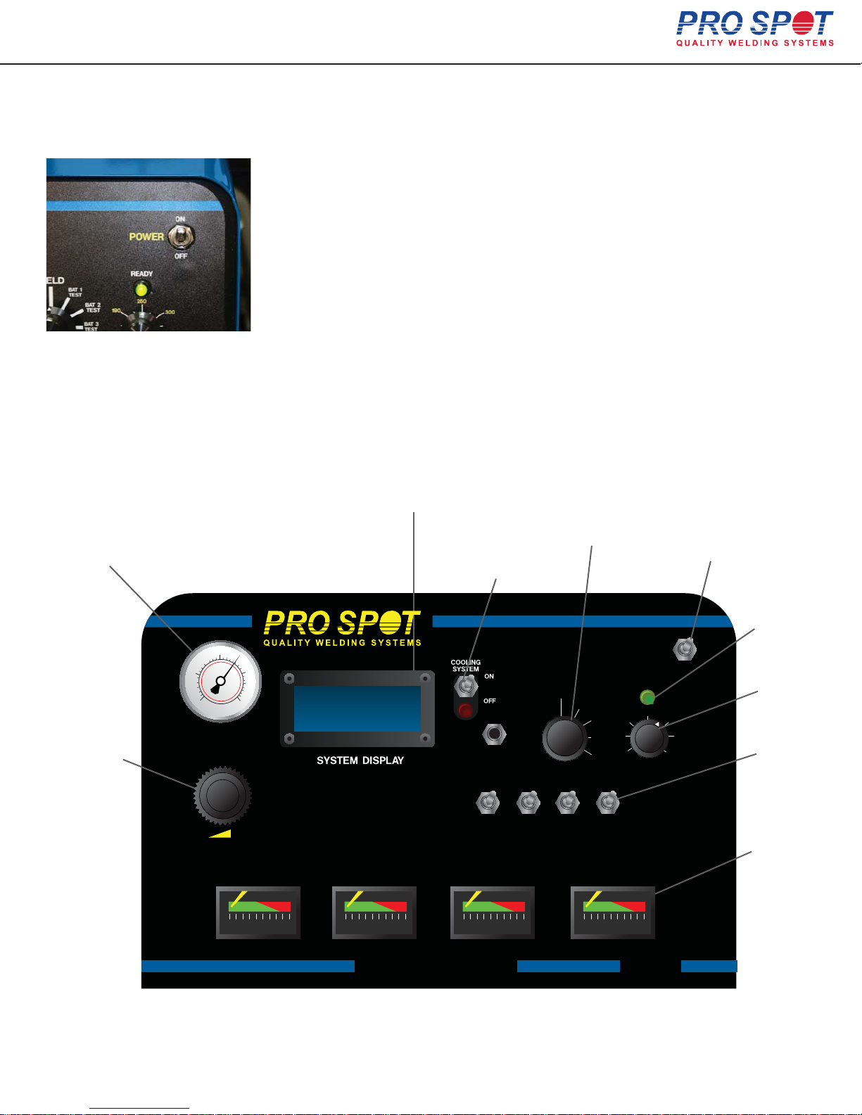
Quick start instructions
Figure 1.1
1. Turn the power switch on the front panel ON (Fig 1.1).
2. Connect Air to the air inlet located on the back panel.
3. Turn the “WELD SWITCH” to the weld position.
4. Turn on the desired amount of battery power by using the battery selector
switches (1-4). For two-sided welding use 3 to 4 batteries in the ON position.
For single-sided welding use one battery. Adjust weld time to 260-300 for two-sided.
120 for single-sided.
5. Place the welding gun at the weld area and press the lower trigger button to weld.
The upper weld button is for spreading the electrodes open for better access.
The welder is now ready to operate. Make sure air pressure is set at 90 PSI.
NOTE: When the welder is not being used, turn the power switch off. Leave
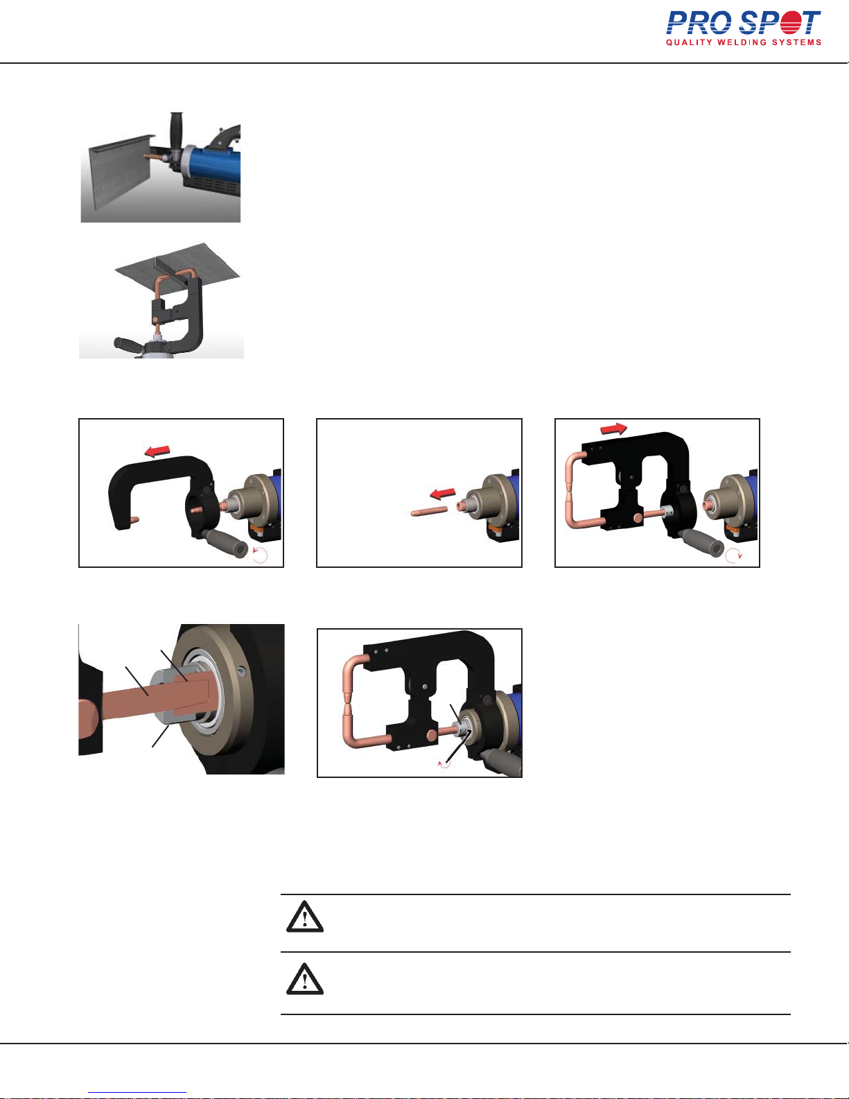
power cord plugged in to allow unit to charge.
Air Pressure
Air Pressure
Regulator
System Display.
Shows battery voltage and charge current.
Hybrid Spot Control Panel
80
40
0
ELECTRODE
PRESSURE
120
160
CHARGING
DC AMPS DC AMPS DC AMPS DC AMPS
Batt1
Batt2
Batt3
Batt4
15.30V
15.30V
15.30V
15.30V
CHARGING
1.5A
1.5A
1.5A
1.5A
Air Cooling
Switch
SERVICE
PUSH TO
TEST BATTERY
ON ON ON ON
BAT 1
BAT 2 BAT 3 BAT 4
CHARGING
WELD
Weld
Switch
BAT 1
TEST
BAT 2
TEST
BAT 3
TEST
BAT 4
TEST
CHARGING
Power
Switch
Ready
Weld
Time Knob
190
POWER
READY
260
ON
OFF
300
Battery
120
WELD
TIME
350
Selector
Switch
Charge
Indicator
Displays
BAT 1
All Info Copyright © Pro Spot International Inc.
BAT 2
BAT 3
HYBRID SPOT
BAT 4
PHS-100
Page 3
4
Page 5
Hybrid Spot
1 Introduction
Congratulations on acquiring your new Hybrid Spot welder!
Team Pro Spot looks forward to supporting you.
You have a welder and support group that will increase your productivity. The integrated features, ease of use,
speed and quality welds that your Hybrid Spot offers will become an important part of your business.
The following information will be needed when you call Pro Spot:
* MODEL TYPE: Hybrid Spot
* SERIAL NO:________________
The serial number is located on the back of the unit.
For parts or service contact your local distributor,
Local number: ____________________________
or in the U.S. call: Toll free:1-877 PRO SPOT or 1-760-407-1414
for a customer service representative.
Visit Pro Spot On-Line: www.prospot.com E-mail: [email protected]
NOTE: You can now order parts online at: prospot.com/store/
The Hybrid Spot welder is used by body shops to
duplicate the welding procedure used by the car
manufacturers.Use of the equipment that is contrary to the
instructionsin this manual can cause personal injury and/or
machine damage.
Pro Spot International, Inc. can in no way be held
responsible for intentional or unintentional damage, and
consequent unlimited loss of profit, loss of income, loss
of business opportunity, loss of use, etc. that originates
from incorrect use of this equipment ir its use in a manner not intended.
Warranty
Pro Spot International, Inc. offers a two-year guarantee
on the welder from the date of delivery. This guarantee covers material defects and assumes normal care
and maintenance. Batteries shipped with the welder
are covered by a 1 year prorated warranty.
The guarantee assumes that:
the equipment is correctly installed and inspected
the equipment has not been altered or rebuilt without
approval from Pro Spot International, Inc.
genuine Pro Spot International, Inc. spare parts are
used to make repairs.
operation and maintenance has been carried out
according to the instructions in this manual.
All claims on warranty must verify that the fault has
occurred within the guarantee period, and that the unit
has been used within its operating range as stated in
the specifications. All claims must include the product
type and serial number. This data is stamped on the
name plate.
Note: This instruction manual provides instructions
for installation, operation, maintenance and troubleshooting.
IMPORTANT!
become familiar with the proper operation of
the welder. Do not neglect to do this as
improper handling may result in personal
injury and damage to the equipment.
IMPORTANT! Lisez ce Mode d’Emploi
attentivement afin de vous familiariser avec
le bon fonctionnement du soudeur. Ne
négligez pas de le faire puisque une mauvaise manipulation peut conduire aux
blessures et dommages à l'équipement.
The drawings in this manual are presented for illustrative purposes only and do not necessarily show the
design of the equipment available on the market at any
given time. The equipment is intended for use in accordance with current trade practice and appropriate safety
regulations. The equipment illustrated in the manual
may be changed without prior notice.
The contents in this publication can be changed without
prior notice.
This publication contains information that is protected by
copyright laws. No part of this publication may be reproduced, stored in a system for information retrieval or be
transmitted in any form, in any manner, without
Pro Spot International, Inc.’s written consent.
Read this manual carefully to
All Info Copyright © Pro Spot International Inc.
1 Introduction
Page 4
5
Page 6
Hybrid Spot
2 Safety
2.0 Safety & Environmental Specifications
The Hybrid Spot welder is designed for indoor use.
The Hybrid Spot welder is designed to operate from 10º C to 40º C.
Do not operate the unit on a slope of more than 10º.
2.1 General
The Hybrid Spot welder has been designed and is tested to meet strict safety requirements. Please read the following instructions carefully before operating the
unit and refer to them as needed to ensure the continued safe operation of the welder.
Information provided in this manual describes the suggested best working practices and should in no way take precedence over individual responsibilities or
local regulations.
The Hybrid Spot Welder is designed to comply with all applicable safety regulations for
this type of equipment. During operation, it is always each individual’s responsibility to consider:
Their own and other’s personal safety.
The safety of the welder through correct use of the equipment in accordance
with the descriptions and instructions provided in this manual.
By observing and following the safety precautions, users of the Hybrid Spot
Spot welder will ensure safer working conditions for themselves and
their fellow workers.
2.2 Warnings and important notices
The following types of safety signs are used on the equipment and in Pro Spot’s
instruction manuals:
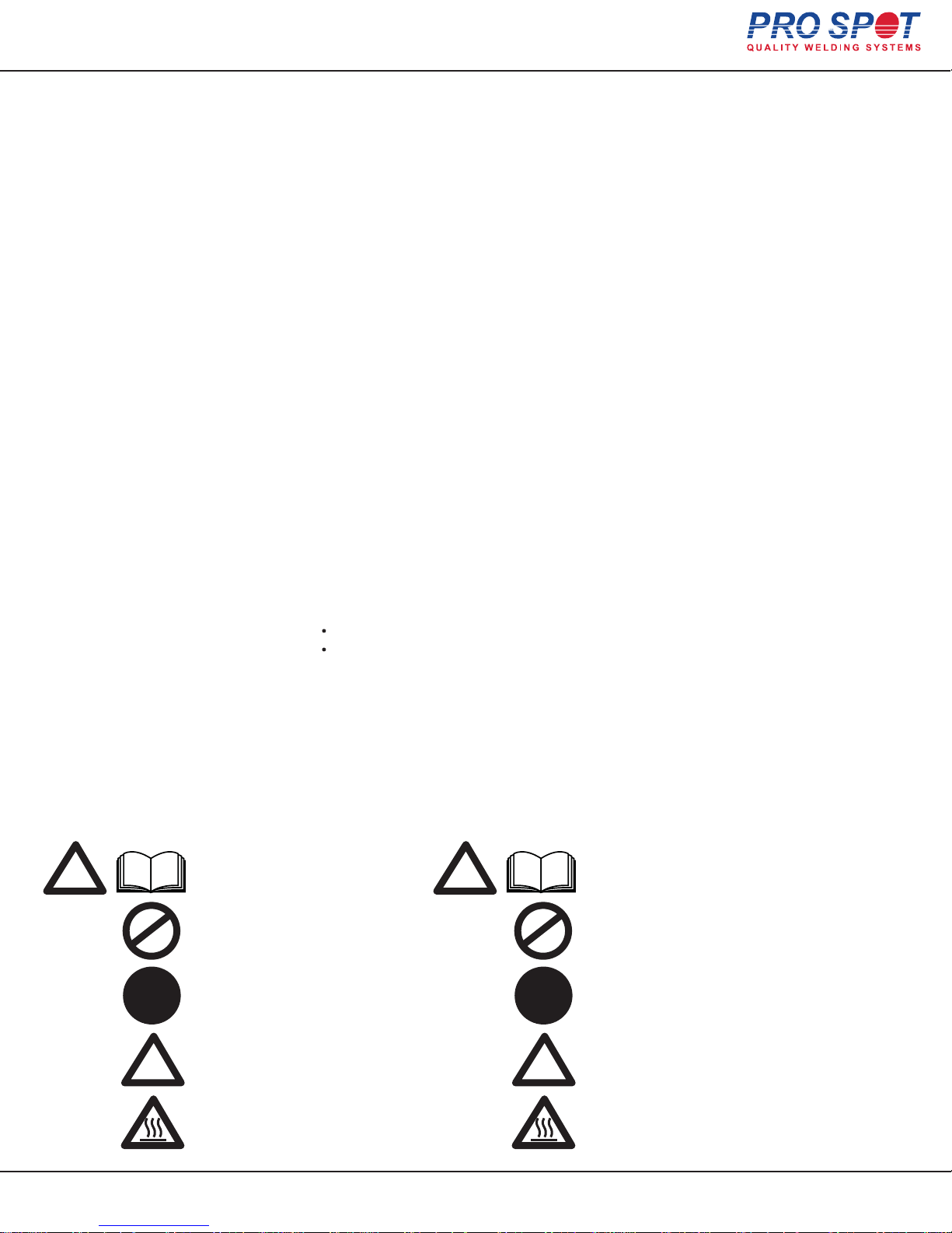
Caution.
!
Read instruction manual.
Attention!
!
Lire Mode d’Emploi.
Prohibited.
Prohibits behaviour that
can cause injury.
Command.
Calls for a specific action.
Warning.
! !
All Info Copyright © Pro Spot International Inc.
Notice of personal injury risk and
or damage to equipment.
Warning.
Some parts of the welder may become
hot after prolonged use.
2 Safety
Interdit.
Interdit aux comportements
qui peuvent provoquer des blessures.
Commande.
Appelle à une action spécifique.
Avertissement.
Avis de risque de blessure personnelle
et / ou d’endommager l'équipement.
Avertissement.
Certaines parties du soudeur peuvent devenir
chaudes après une utilisation prolongée.
Page 5
6
Page 7
Hybrid Spot
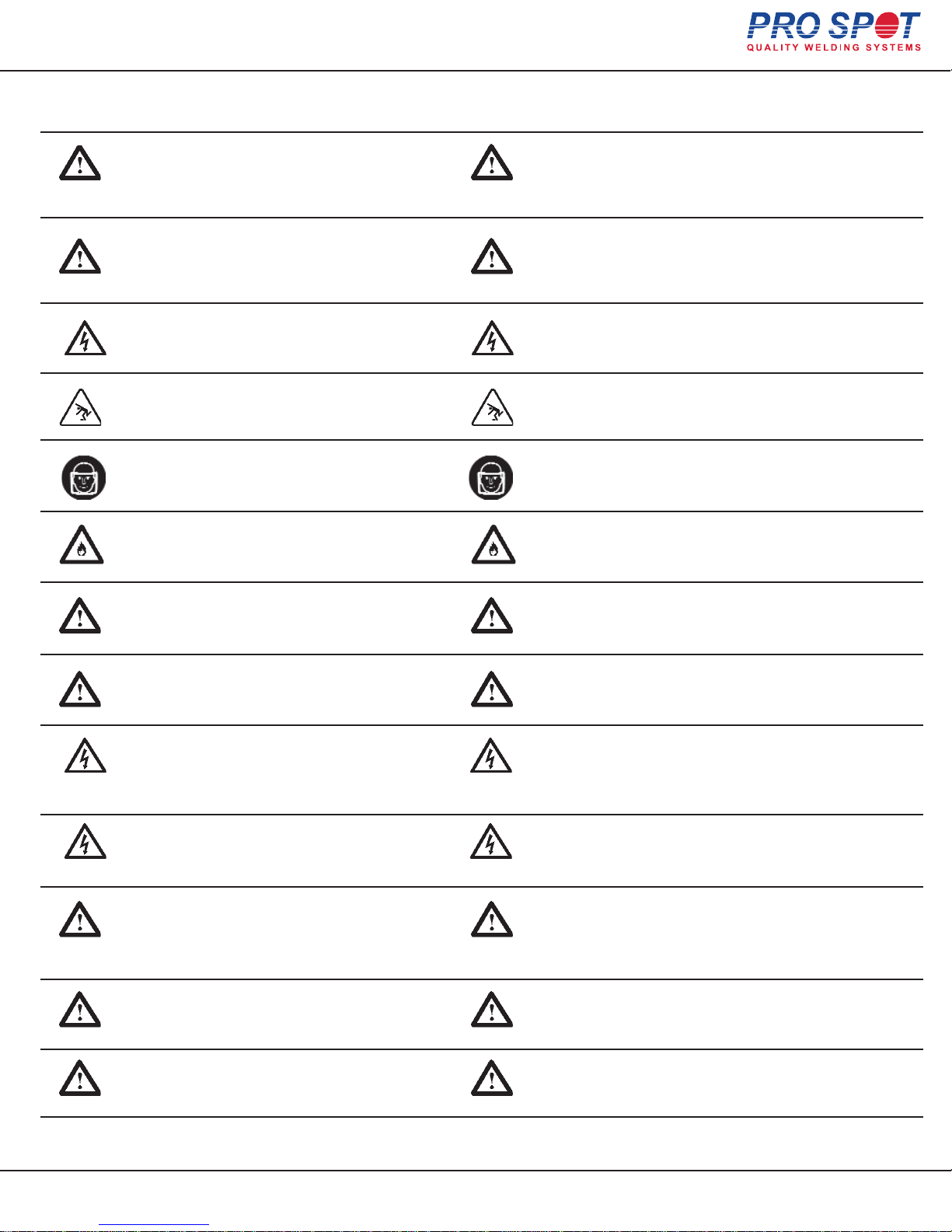
The following warnings and important notices are used in the instruction manual:
WARNING! Do not operate or place
the welder near water, in wet locations
or outdoors. Risk for injuries or damage
to the welder.
WARNING! Do not place the welder on
unstable or uneven ground. The welder
might tip causing personal injuries or
serious damage to the welder.
WARNING! All electrical connections
must be made by a qualified electrician.
Risk for electrical shock.
WARNING! Loose cables and hoses
present tripping risks. Risk for injuries.
WARNING! Make sure to use welding
goggles when spot welding. The sparks
might otherwise injure the eyes.
WARNING! Sparks from welding
could start a fire. Risk for injuries.
ATTENTION! Ne pas faire fonctionner le soudeur
près de l'eau, en voie humide , ou à l’éxterieur .
Risque de blessures ou de dommages au
soudeur.
ATTENTION! Ne placez pas le soudeur sur un sol
instable ou irrégulière. Le soudeur peut basculer
causant des lésions corporelles ou des dommages
graves au soudeur.
ATTENTION! Toutes les connexions électriques
doivent être faites par un électricien qualifié.
Risque de choc électrique.
ATTENTION! Câbles et tuyaux lâches présentent des
risques de déclenchement. Risque de blessures
ATTENTION! Veuillez utiliser des lunettes de soudeur
sur place. Les étincelles pourraient autrement blesser
les yeux.
ATTENTION! Étincelles de soudure pourrait provoquer
une incendie. Risque de blessures.
WARNING! Risk for damage to materials
close to the weld, e.g to glass or textiles.
WARNING! For proper cooling efficiency,
never operate the welder without connecting
it to the compressed air source.
WARNING! All service and maintenance
must be carried out by Pro Spot service
personnel and service support. Risk for
electrical shock.
WARNING! Unplug the welder from the
wall outlet before servicing, cleaning or
maintenance. Risk for electrical shock.
IMPORTANT! The welder may only be
used by qualified personnel. The user of
the welder must have knowledge of spot welding
and of alignment of collision-damaged vehicles.
IMPORTANT! Do not turn off the welder
while cooling is activated!
ATTENTION! Risque de dommages aux matériaux à
proximité de la soudure, par exemple verre ou textiles.
ATTENTION! Pour refroidissement efficace, ne jamais
soudeur sans attacher à la source d'air comprimé.
ATTENTION! Tout le service et l'entretien doivent être
effectués par personnel et soutien de service Pro
Spot. Risque de choc électrique.
ATTENTION! Débranchez le soudeur de la prise
murale avant l'entretien, ou nettoyage. Risque de
choc électrique.
IMPORTANT! Le soudeur peut seulement être utilisé
par personnel qualifié. L'utilisateur du soudeur doit
avoir une connaissance de soudage par points et
l'alignement des véhicules endommagés par collisions.
IMPORTANT! N'éteignez pas le soudeur pendant que le
refroidissement est activé!
IMPORTANT! The air must be clean and
free from oil and moisture. Use filter.
All Info Copyright © Pro Spot International Inc.
2 Safety
IMPORTANT! L'air doit être propre et sans huile et
humidité. Utilisez un filtre
Page 6
7
Page 8
Hybrid Spot
2.2 Warnings and important notices (cont’d.)
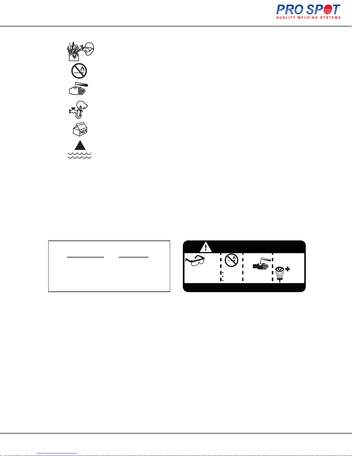
SHIELD EYES EXPLOSIVE GASES
Can cause blindness or injury.
NO SPARKS, FLAMES OR SMOKING
SULFURIC ACID
Can cause blindness or severe burns.
FLUSH EYES IMMEDIATELY
With water. Get medical help fast.
IF SWALLOWED
Drink as much water or milk as possible. Get medical help fast.
!
IF SPILLED
Spread baking SODA over spill, then dilute with large amounts of water.
KEEP OUT OF REACH OF CHILDREN
Do Not Tip, Keep Vent Caps Tight And Level
PROPOSITION 65 WARNING
Battery posts, terminals and related accessories contain lead and lead
compounds, chemicals known to the State of California to cause cancer and
reproductive harm. Batteries also contain other chemicals known to the State
of California to cause cancer. Wash hands after handling.
OPEN CIRCUIT VOLTAGE AS IT RELATES TO STATE OF CHARGE
Open Circuit Voltage* State of Charge
12.80 or greater.............................100%
12.60..................................75%
12.30..................................50%
12.00..................................25%
12.00....................................0
* The actual stabilized OCV can only be determined after the
battery has been disconnected from the charger for 24 hours.
Battery Warnings
DANGER/POISON
SHIELD
EYES.
EXPLOSIVE
GASES CAN
CAUSE BLINDNESS
OR INJURY.
KEEP OUT OF REACH OF CHILDREN
NO
SPARKS
FLAMES
SMOKING
SULFURIC
ACID
CAN
CAUSE
BLINDNESS OR
SEVERE BURNS.
FLUSH EYES
IMMEDIATELY
WITH WATER.
MEDICAL
HELP FAST.
GET
2.3 Safety devices
When the Spot Gun is used continuously, the welding cables get hot.
To prevent the welder from malfunctioning due to overheating, it is
2.3.1 Cooling
cooled using the built-in air cooling system. The air cooling system
cools the welding cables, cable ends and the spot gun.
To activate the cooling system, turn the air cooling ON. Compressed air
will flow through the weld cables. It is not necessary to leave on at all
times, but should be used when the weld cables are hot to the touch.
For best results, let the welder rest when cables are too hot. Cooler weld
cables result in better weld performance.
All Info Copyright © Pro Spot International Inc.
2 Safety
Page 7
8
Page 9
Hybrid Spot
3 Installation
3.1 General
The Hybrid Spot welder is inspected and tested prior to leaving the factory to
guarantee consistent quality and the highest possible reliability. Follow the installation tips and operating instructions below to ensure user safety and proper
welder performance.
WARNING! Do not operate or place the welder near water, in wet
locations or outdoors. Risk for injuries or damage to the welder.
WARNING! Do not place the welder on unstable or uneven
ground. The welder might fall causing personal injuries and damage to
the welder. Do not operate on a slope of more than 10º.
IMPORTANT! It is the responsibility of the owner to ensure that
the equipment has been installed as specified in the instructions provided. It is also the owner's responsibility to ensure that the welder
is inspected in accordance with applicable regulations before it is
put into service. Do not use for thawing out frozen water pipes (17.1)
ATTENTION! Ne pas faire fonctionner le soudeur près de l'eau, en voie
humide ou à l'extérieur. Risque de blessures ou de dommages au soudeur.
ATTENTION! Ne placez pas le soudeur sur un sol instable ou irrégulière.
Le soudeur peut tomber causant des dommages graves au soudeur.
Ne pas utiliser sur une pente de plus de 10º
IMPORTANT! C'est la responsabilité du propriétaire de s'assurer que
l'équipement a été installé comme spécifié dans les instructions fournies.
C'est aussi la responsabilité du propriétaire de s’assurer que le soudeur est
inspecté conforment à la réglementation applicable avant qu'il ne soit mise
en service. Ne pas utiliser pour dégeler les conduites d'eau congelées (17.1)
A grounded electrical plug must be installed (refer to section 3.4 “Connection of
electrical supply”).
3.2 Packaging and delivery inspection
Check the contents of the shipping container against the packing list, consignment note, or other delivery documentation to verify that everything is included
and in the correct quantity. Check the Spot Welder carefully to make sure that
no damage has occurred during transport. If anything is damaged or missing, the
welder may be unsafe to use till the part is repaired or replaced. If anything is
missing, please contact your supplier. Remove all packaging material from the
welder.
3.3 Welder assembly
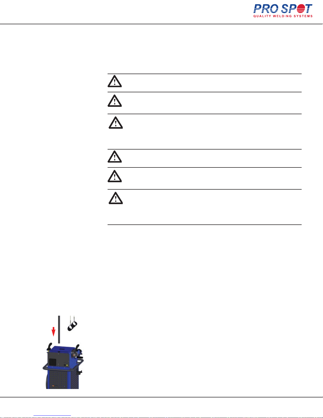
For your convenience, the welder ships fully assembled.
Insert the support arm (boom) as shown in Figure 3.1
Figure 3.1
All Info Copyright © Pro Spot International Inc.
3 Installation
Page 8
9
Page 10
Hybrid Spot
3.4 Battery Installation
Preferred
Recommended batteries — Centennial Commercial
Other
Recommended batteries — Deka
C-31-10AP CCA1100
31P, P# - 1231PMF, CCA1000, RES 185, REF 1190
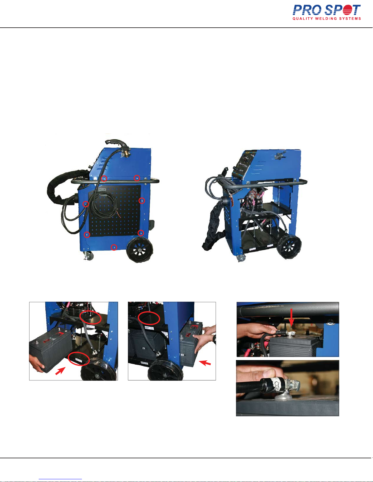
When you rst receive your hybrid battery spot welder you will need to purchase 4 - 31P batteries at >=1000A that
have pole style car battery terminals. Remove the 7 screws on both side panels and then remove the panels.
Insert batteries from the side,
be sure to put check the labels
(circled in the image) and set the
batteries poles facing the correct
direction.
The rear lower battery has to be
installed form the opening in the
back of the welder.
Place the leads (red on positive and
black on negative) on the battery terminals and tighten with a 1/2” socket.
Do not over tighten.
All Info Copyright © Pro Spot International Inc.
3 Installation
Page 9
10
Page 11
Hybrid Spot
3.5 Connection of electrical supply
Battery charging system:
The Hybrid Spot welder is equipped with an on-board charging system that
will charge all 4 batteries at once.
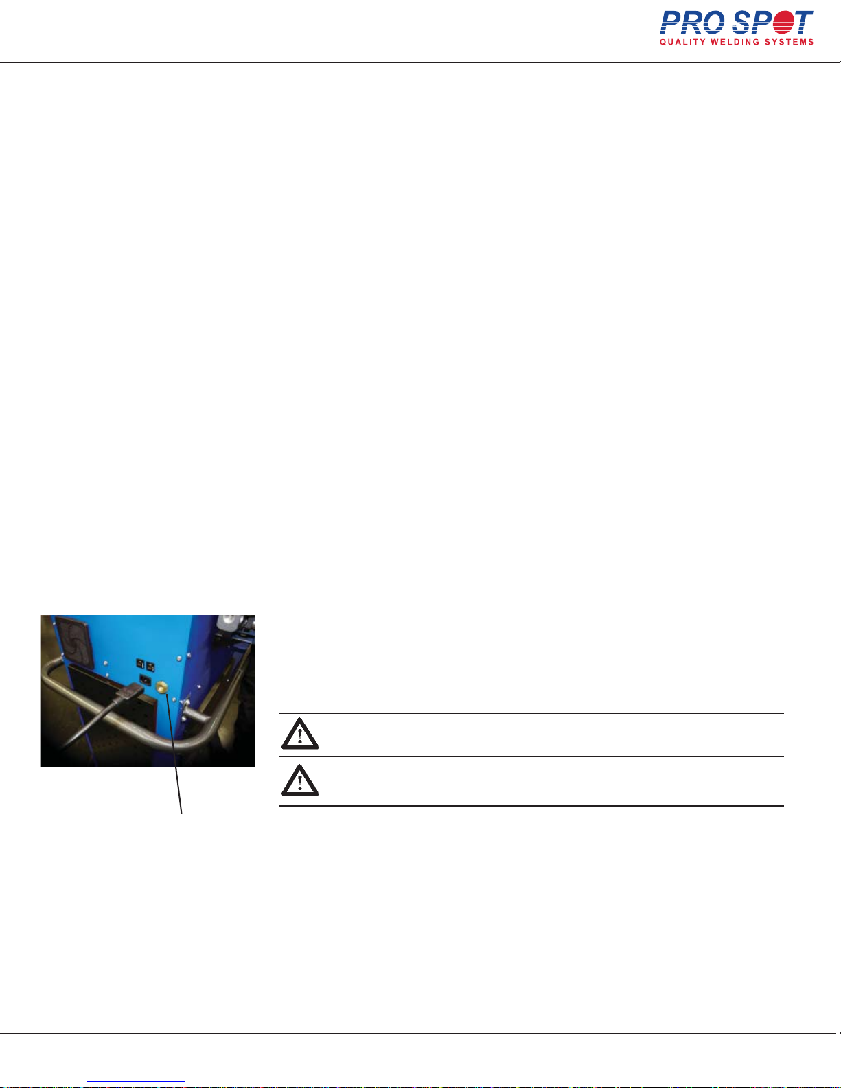
To activate charging, simply plug in the power cord to the outlet on the back
of the welder Fig 3.2 and the supply 120VAC or 240VAC for Europe, Australia,
and China. The power supply switches automatically between
120VAC and 240VAC.
It is possible to weld while the charging is activated; the charger will automatically
switch off when welding. The charger will turn back on 2 minutes after the last weld is
made. To check each battery’s voltage, turn the WELD switch to Bat 1 Test,
Bat 2 Test, etc.
To check the battery under load press “PUSH TO TEST BATTERY” button
for 3 seconds to see loaded voltage. Repeat for each battery.
3.6 Connection of pneumatic air supply
The Hybrid Spot welder must be connected to a pneumatic air network.
(100 PSI to 130 PSI)
1. Connect the welder to the air supply via the threaded input port at
the rear of the welder using a standard connector.
2. If not already set, adjust the air pressure setting on the welder front panel to
90 PSI (4-5 bar) (refer to section 4.5 “Setting the pneumatic air pressure”).
IMPORTANT! The air must be clean and free from oil and
moisture. Use a filter.
Figure 3.2
Air supply port
IMPORTANT! L'air doit être propre sans huile et
humidité. Utilisez un filtre.
All Info Copyright © Pro Spot International Inc.
3 Installation
Page 9
11
Page 12
Hybrid Spot
4 Operation
4.1 Before you begin welding
Before you begin welding, be sure to read and understand the following instructions.
The Hybrid Spot is a Resistance Spot Welder that was designed for the collision
repair industry. It duplicates the welding procedure usedby the car manufacturers.
It is important to understand the design and function of
this welder before operating it.
ELECTRICITY ONLY: The welder uses only electricity to create the welds unlike the
MIG welder which uses an arc from a feeding wire to build a weld nugget using
inert gas and the feeding wire material.
PRESSURE: The welder has a built in air cylinder that compresses the Double-Sided
Gun’s welding tips together automatically when triggered. The compression is an
important part of a good resistance weld. The pressure is adjustable from the
Control Panel. The optimum welding pressure varies between 60-90 PSI (4-6.5
BAR). 90 PSI seems to be a common starting pressure. As a rule, increase pressure with thicker metals but remember that too much pressure could decrease the
resistance of the metal between the electrodes, resulting in poor weld penetration.
CURRENT: Another important aspect of a weld is the current applied through the
work
piece. A weld is created when a large current is transferred through the layers of sheet metal. The resistance in the metal causes the area to heat up and
fuse the sheets together in a nugget.
WELD PROGRAM: Maintaining the air pressure after the current shuts off makes
the weld cool down under pressure resulting in a harder, stronger weld. This feature is built in to the welder’s weld control program and is engaged automatically during a weld cycle.
TIME: The Timer controls the duration of the current applied during the weld
cycle. The ideal is to get a weld that uses higher current and shorter time to control heat buildup.
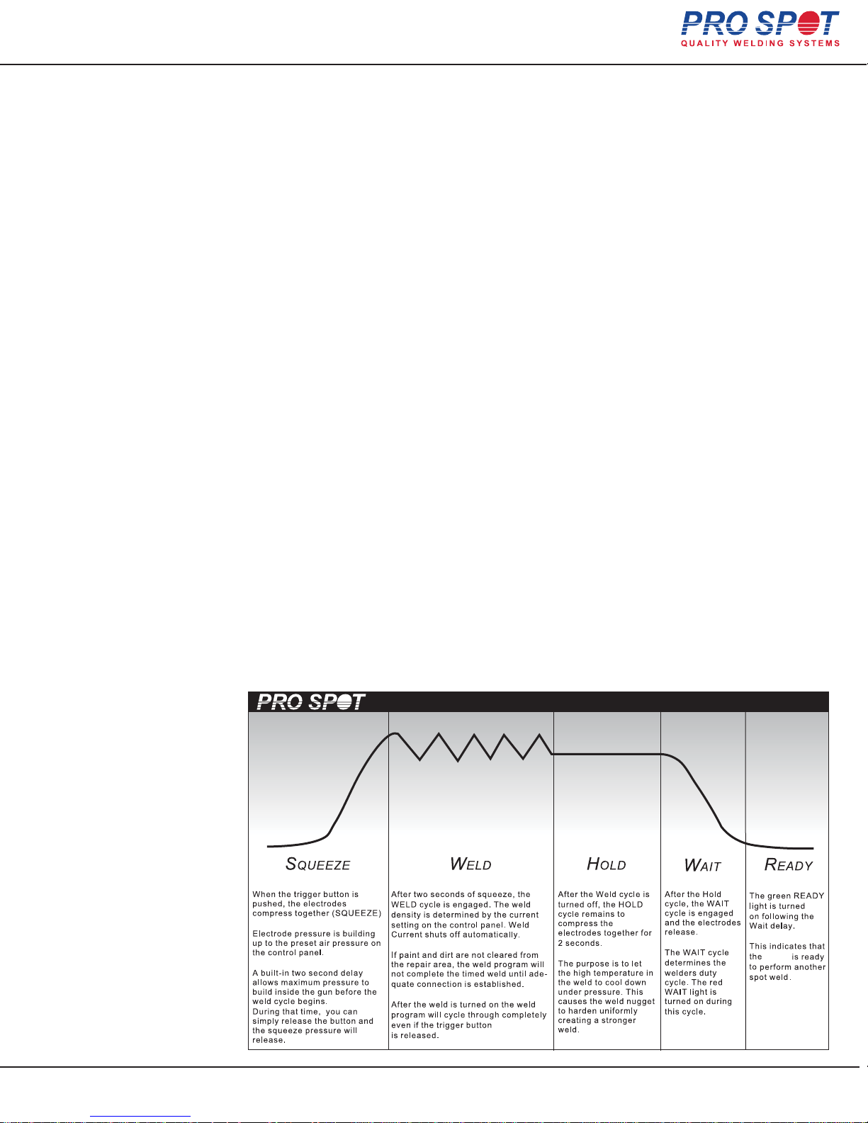
WELD CYCLE CHART
All Info Copyright © Pro Spot International Inc.
4 Operation
Page 10
12
welder
Page 13
Hybrid Spot
4.2 About your welder
4.2.1 Welder Overview & Technical Specifications
The welder is supplied with four high performance 12V batteries.
Input voltage:
The actual voltage and frequency is stated on the rear panel name plate.
Open circuit output voltage 15V max.
120VAC or 240VAC 1 Phase 5A
Welding amperage: 10,000A max
Cable length: 8’ (2.5m) standard
Electrode force: At 7 bars (90 PSI)-280 DaN (616 Lb)
At 8 bars (116 PSI)-320 DaN (720 Lb)
Cooling system: Air (1 fan), Compressed air
(weld gun and weld cables)
Shipping Weight (standard): 515lb (234kg)
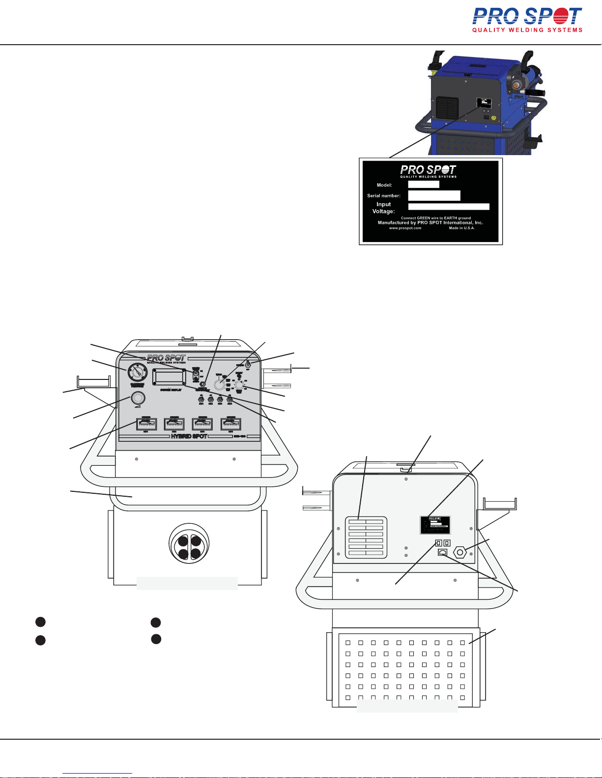
4.2.2 Getting familiar with your welder
Air Cooling Switch
Air Pressure Gauge
Double-Sided
Gun Holder
Air Pressure
Regulator
Battery Charge
Indicator
Battery Test Button
Batt1
15.30V
1.5A
Batt2
15.30V
1.5A
Batt3
15.30V
1.5A
Batt4
15.30V
1.5A
Weld Switch & Battery Test Switch
Weld Time Switch
Display Screen
Battery Selector Switches
Power Switch
Single-Sided
Gun Holder
PHS-100
90021
120VAC or 240VAC 1 Phase 5A
The name plate is at the rear of the welder unit.
The required voltage is indicated on the label.
Welding output is rated at 15V.
Cable Holder Bracket
Cooling Fan
Name Plate shows:
Input voltage,
Serial number, etc.
Tool Tray
3
1
4
2
Figure 4.1 Front View
WELD CABLES CONFIGURATION
1
Two-Sided spot gun cable
Two-Sided ground cable
2
Single-Sided Weld Gun cable
3
4
Single-Sided ground cable
All Info Copyright © Pro Spot International Inc.
4 Operation
Fuses
Figure 4.2 Back View
Connect filtered air
100 PSI 7 BAR (min)
Power Input
Back Panel
Tool board
Page 11
13
Page 14
Hybrid Spot
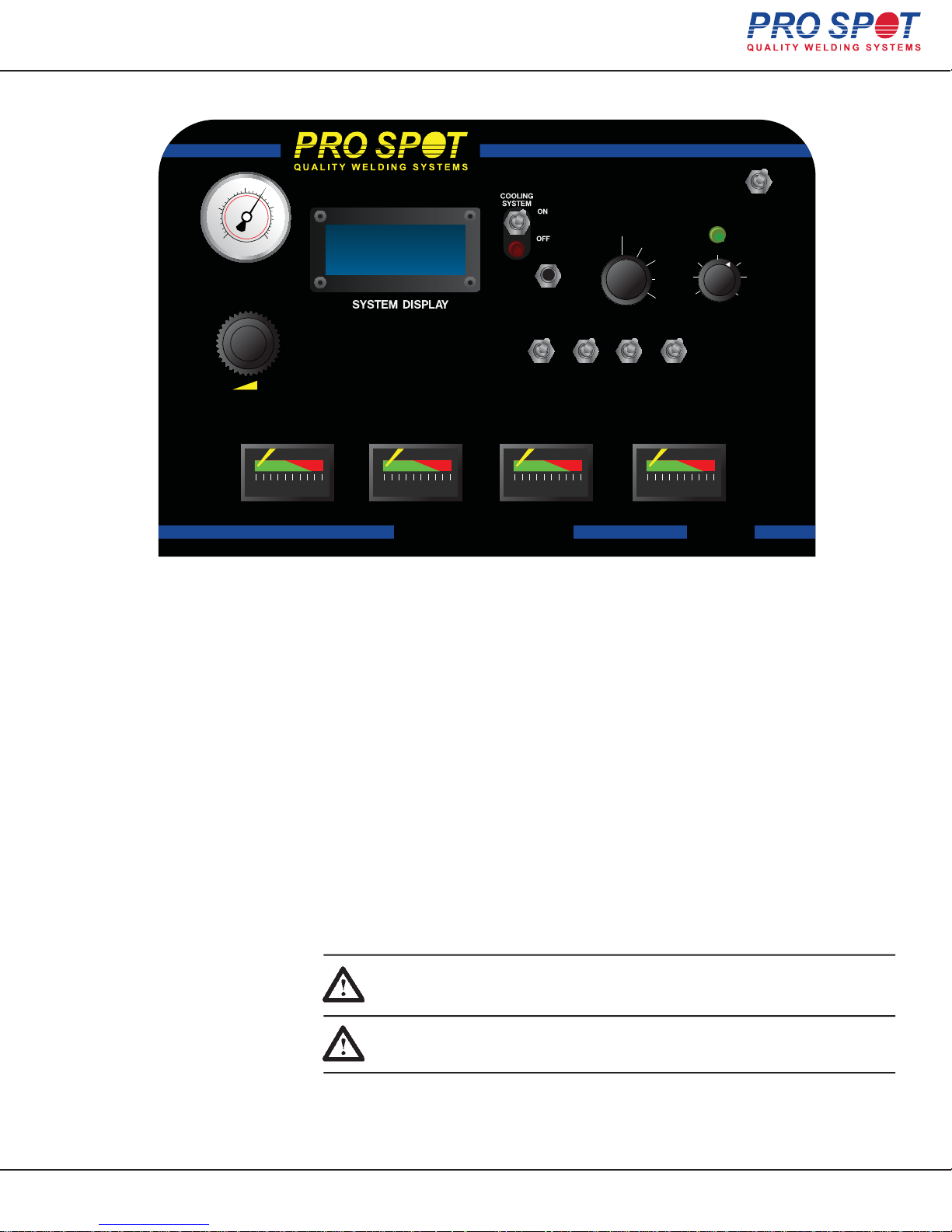
4.2.3 Hybrid Spot Control Panel
80
40
0
ELECTRODE
PRESSURE
120
160
Batt1
Batt2
Batt3
Batt4
15.30V
15.30V
15.30V
15.30V
1.5A
1.5A
1.5A
1.5A
SERVICE
PUSH TO
TEST BATTERY
ON ON ON ON
BAT 1
BAT 2 BAT 3 BAT 4
WELD
BAT 1
TEST
BAT 2
TEST
BAT 3
TEST
BAT 4
TEST
ON
POWER
OFF
READY
260
190
120
WELD
TIME
300
350
CHARGING
DC AMPS DC AMPS DC AMPS DC AMPS
BAT 1
4.3 Turning on the welder
CHARGING
BAT 2
HYBRID SPOT
CHARGING
BAT 3
CHARGING
BAT 4
PHS-100
Figure 4.3 The Hybrid Spot Control Panel
1. Toggle the power switch on the front panel to “ON”.
2. The Hybrid Spot is now ready to use.
3. The System Display window will show the battery
voltage & charge current on all four batteries.
4. The weld toggle switch must be in position “WELD” to perform welding
duties. Start with 3 batteries ON, (BAT 1, 2, 3 switches ON) and adjust
the weld time to 260-300. If more power is required, turn BAT 4 ON.
5. Increase the WELD TIME knob if a longer weld time is needed. NOTE: An
increased weld time will drain the batteries quicker. Also, always clean and
sharpen weld electrodes to maintain welding performance.
All Info Copyright © Pro Spot International Inc.
IMPORTANT! Make sure to read the instruction manual before operating
the welder. Only trained personnel should use this welder.
IMPORTANT! Assurez-vous de lire le Mode d’Emploi avant d'opérer
le soudeur. Seul le personnel qualifié devrait utiliser ce soudeur.
4 Operation
Page 12
14
Page 15
Hybrid Spot
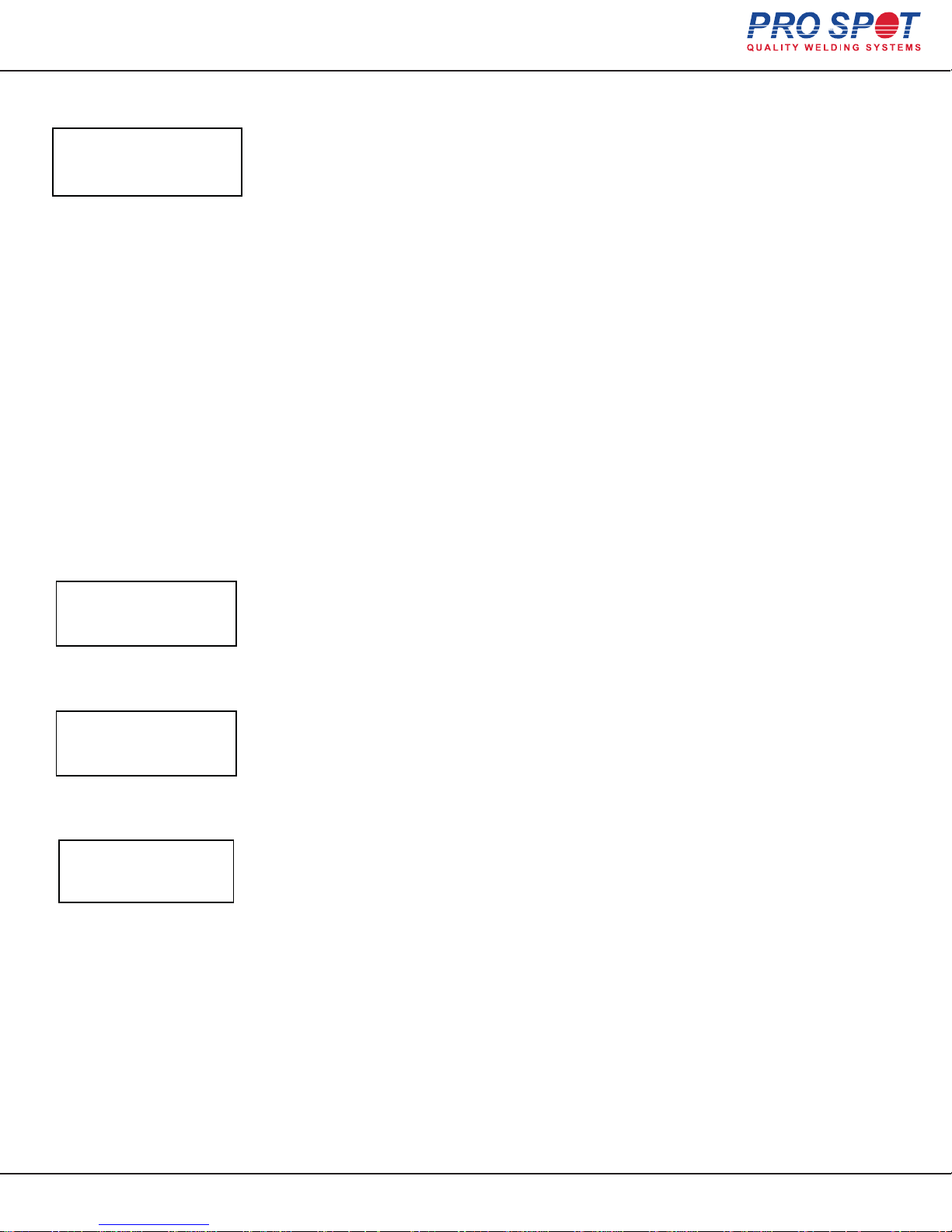
4.3.1 Checking the Battery Voltage
Batt1
Weld Count:
Test: 12.66V
Fig. 1
3
When batteries are fully charged they should be between 12.8 – 13.8V with the charger turned off.
When power cord is attached to 120VAC or 240VAC the batteries get charged automatically. The
status of charging is displayed on front panel display (unplugged). To test each battery under load,
select batteries 1-4 with the WELD switch. Note the voltage in the display screen. Push battery
TEST button located to the left of the weld switch for 2-3 seconds; note the load voltage on the
display screen (Fig. 1). If the voltage dips down under 12V, charge the batteries and check again. If
it is still low, check and/or replace the battery. The weld count indicates the total number of welds
on the unit.
VERY IMPORTANT: Do not use any other battery than those supplied by Pro Spot.
Hybrid Welder Battery Charging Instructions:
To charge the batteries in the Hybrid Welder, simply plug the power cord into a 120VAC or 240VAC outlet. The welder may
be switched on or off during charging; this does not affect the charge cycle. If the operator welds while the batteries are
charging, the charger will automatically shut off to protect the batteries. When 2 minutes have passed since the last weld,
charging will resume automatically. While the batteries are being charged, the LCD display will show the charging voltage
and current for each battery. During a normal cycle, the battery voltage can rise as high as 15.5V for several hours, and will
then be reduced to 14.4V for the remainder of the charging cycle. After 10 hours of charging, the voltage will be reduced to
13.8V to provide a “float” charge. If the charger is left plugged in for more than 24 hours, it will go into standby mode. In this
mode, the charger will provide a topping voltage to the batteries every 4 days to ensure that the welder will always be ready
for immediate use. The welder may be left plugged in constantly; this will not damage the batteries.
4.3.2 Battery Alerts
Batt1
Batt2
Batt3
Batt4
Batt1
Batt2
Batt3
Batt4
Low Battery
15.30V
15.30V
15.30V
Fig. 2
15.30V
SERVICE
15.30V
15.30V
Fig. 3
Check Battery
Water Levels
Fig. 4
0.0A
0.0A
0.0A
0.0A
0.0A
0.0A
During the charge cycle or welder operation, the LCD may display status alerts to indicate when
user action is necessary to keep the batteries in good condition. These alerts are described below:
LOW VOLTAGE
This alert indicates that the battery has reached the maximum safe discharge level and needs to
be charged (Fig. 2). The welder will disable the depleted battery and sound an audible alert if the
operator tries to use this battery to weld. Any batteries not showing this alert can still be used to
weld. To clear this alert, plug in the power cord and allow the batteries to charge. When any low
battery is recharged to at least 13.8V, the alert will clear automatically and welding can resume.
SERVICE
This alert indicates that the battery voltage has fallen below 11.5V and the battery needs to be
replaced (Fig. 3). The charger will not attempt to charge a battery that has discharged this low, as
doing so might cause the battery or charger to overheat.
WARNING: Warranty is voided if battery water level has not been maintained. Check battery water
level at consistent intervals (Fig. 4).
All Info Copyright © Pro Spot International Inc.
4 Operation
Page 13
15
Page 16

Hybrid Spot
4.4 Choosing the weld mode
The Hybrid Spot is a multi-functional resistance spot welder. It is equipped with a
four weld cable system for your convenience. Two of the weld cables are connected
to the Two-Sided Spot Gun and the other two are connected to the
Single-Sided Weld Gun.
For Two-Sided welding, use 3 to 4 batteries in the ON position.
For Single-Sided welding, use 1 battery in the ON position. Using more than one
battery for Single-Sided welding will result in burn through due to excessive
weld power.
4.5 Setting the pneumatic air pressure
Pneumatic air is used for:
- forcing the spot gun to close and open.
- cooling the welding cables that are connected to the spot gun.
The air pressure is regulated with the air regulator, and the set pressure is indicated on the pressure gauge. Default pressure is 90 PSI.
Change the air pressure as follows:
1. Unlock the pressure regulator by pulling on the adjustor knob till it snaps into
the unlocked position.
2. Turn the pressure regulator knob clockwise to increase or counter-clockwise to
decrease the air pressure.
3. Lock the pressure regulator by returning the knob to the lock position.
4.6 - 4.7 Setting/Changing the weld program
There are two different ways to set the weld power. One is by selecting
1-4 batteries for two sided welding. It is reccommended to use 3-4
batteries for all two sided welding procedures, if using 1-2 batteries,
weld power will be limited and will create a substandard weld.
The other adjustment available is the WELD TIME Switch - it is
used to set the duration of the weld. 250ms is a recommended setting
for weld time, if you choose a longer weld time, you will risk draining
of the batteries more quickly.
Always keep electrodes sharpened and properly aligned,
this will minimize the need for high weld times & will help to
maintain weld quality.
All Info Copyright © Pro Spot International Inc.
4 Operation
Page 15
16
Page 17

Hybrid Spot
4.4 Choosing the weld mode
The Hybrid Spot is a multi-functional resistance spot welder. It is equipped with a
four weld cable system for your convenience. Two of the weld cables are connected
to the Two-Sided Spot Gun and the other two are connected to the
Single-Sided Weld Gun.
For Two-Sided welding, use 3 to 4 batteries in the ON position.
For Single-Sided welding, use 1 battery in the ON position. Using more than one
battery for Single-Sided welding will result in burn through due to excessive
weld power.
4.5 Setting the pneumatic air pressure
Pneumatic air is used for:
- forcing the spot gun to close and open.
- cooling the welding cables that are connected to the spot gun.
The air pressure is regulated with the air regulator, and the set pressure is indicated on the pressure gauge. Default pressure is 90 PSI.
Change the air pressure as follows:
1. Unlock the pressure regulator by pulling on the adjustor knob till it snaps into
the unlocked position.
2. Turn the pressure regulator knob clockwise to increase or counter-clockwise to
decrease the air pressure.
3. Lock the pressure regulator by returning the knob to the lock position.
4.6 - 4.7 Setting/Changing the weld program
There are two different ways to set the weld power. One is by selecting
1-4 batteries for two sided welding. It is reccommended to use 3-4
batteries for all two sided welding procedures, if using 1-2 batteries,
weld power will be limited and will create a substandard weld.
The other adjustment available is the WELD TIME Switch - it is
used to set the duration of the weld. 250ms is a recommended setting
for weld time, if you choose a longer weld time, you will risk draining
of the batteries more quickly.
Always keep electrodes sharpened and properly aligned,
this will minimize the need for high weld times & will help to
maintain weld quality.
All Info Copyright © Pro Spot International Inc.
4 Operation
Page 15
17
Page 18
Hybrid Spot
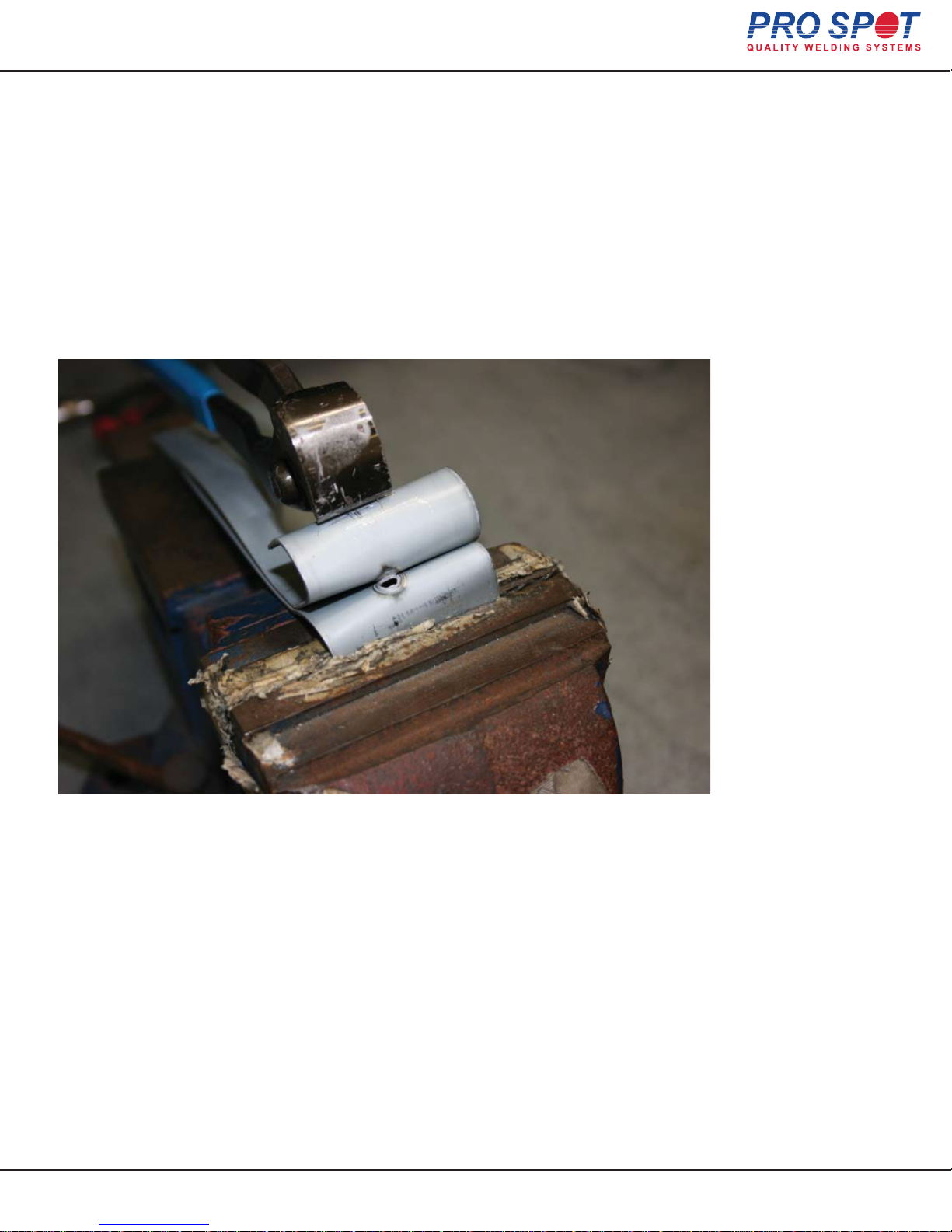
4.8 Checking Weld Quality
Peel Test
To perform destructive weld testing: Make a weld on two test pieces and tear them apart using a
Vise & Vise-Grip pliers. Note the strength of the weld. It is important to test the same materials that you
would normally use for repair in a weld destructive testing procedure. Expect to tear a hole around the
weld nugget as the two metals are peeled apart.
IMPORTANT: Use the same metal as you are welding.
All Info Copyright © Pro Spot International Inc.
4 Operation
Page 16
18
Page 19
Hybrid Spot
5 Double-Sided Welding
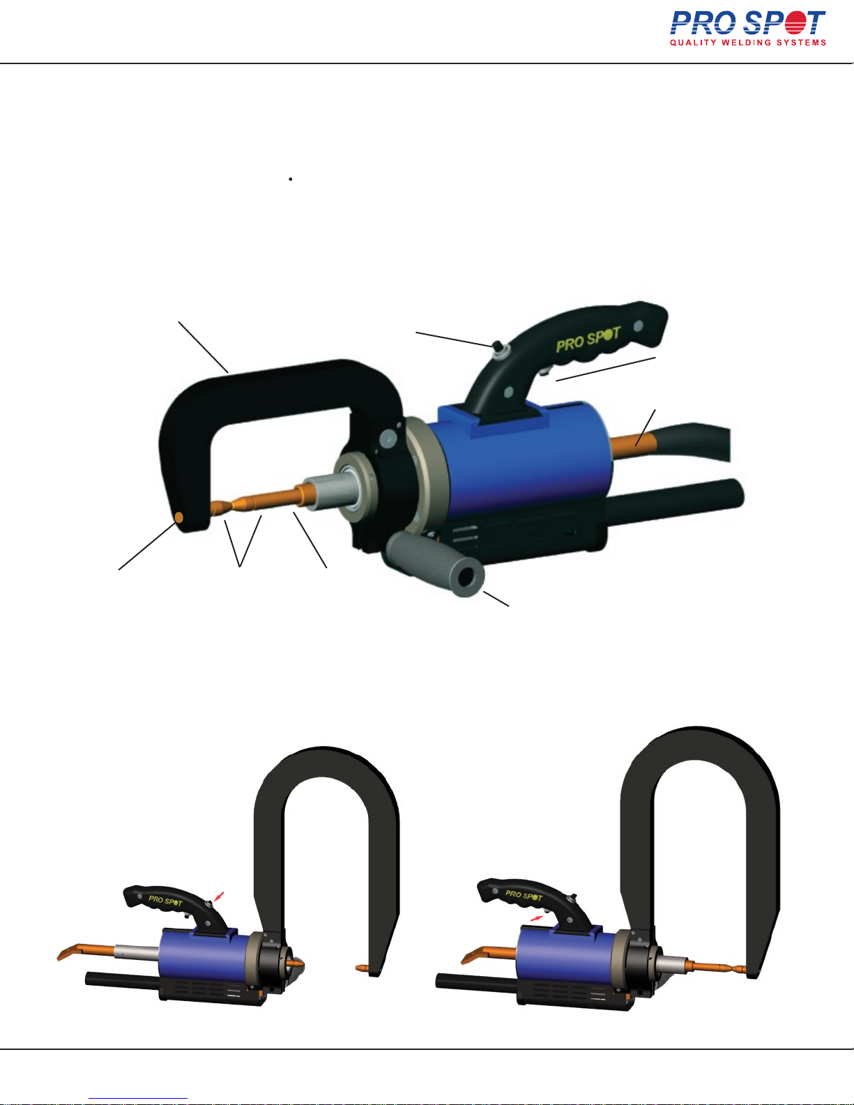
5.1 PS-500 Double-Acting Spot Gun
The spot gun is used for the following weld programs:
Two-Sided spot welding - HSS Galvanized steel, Mild steel, Weld Bonding,
Boron Steel, Pulse welding and Custom Modes
(see section 4.8 “Setting the default welding programs”)
5.1.1 PS-500 Component Diagram
PS-302
C-Arm
PS-103-CM
20mm Shank
PS-025
Welding Cap
PS-1101-CM
60mm Shank
F-44
Release Trigger Switch
Figure 5.1 PS-500 Spot Gun - Component Diagram
5.1.2 Using the Double-Acting Gun
F-44
Weld Trigger Switch
Weld Shaft
PS-5203
Clamping Handle
Push this button to open electrodes wide. Push this button to close electrodes and weld.
All Info Copyright © Pro Spot International Inc.
5 Double-Sided Welding
Page 17
19
Page 20
Hybrid Spot
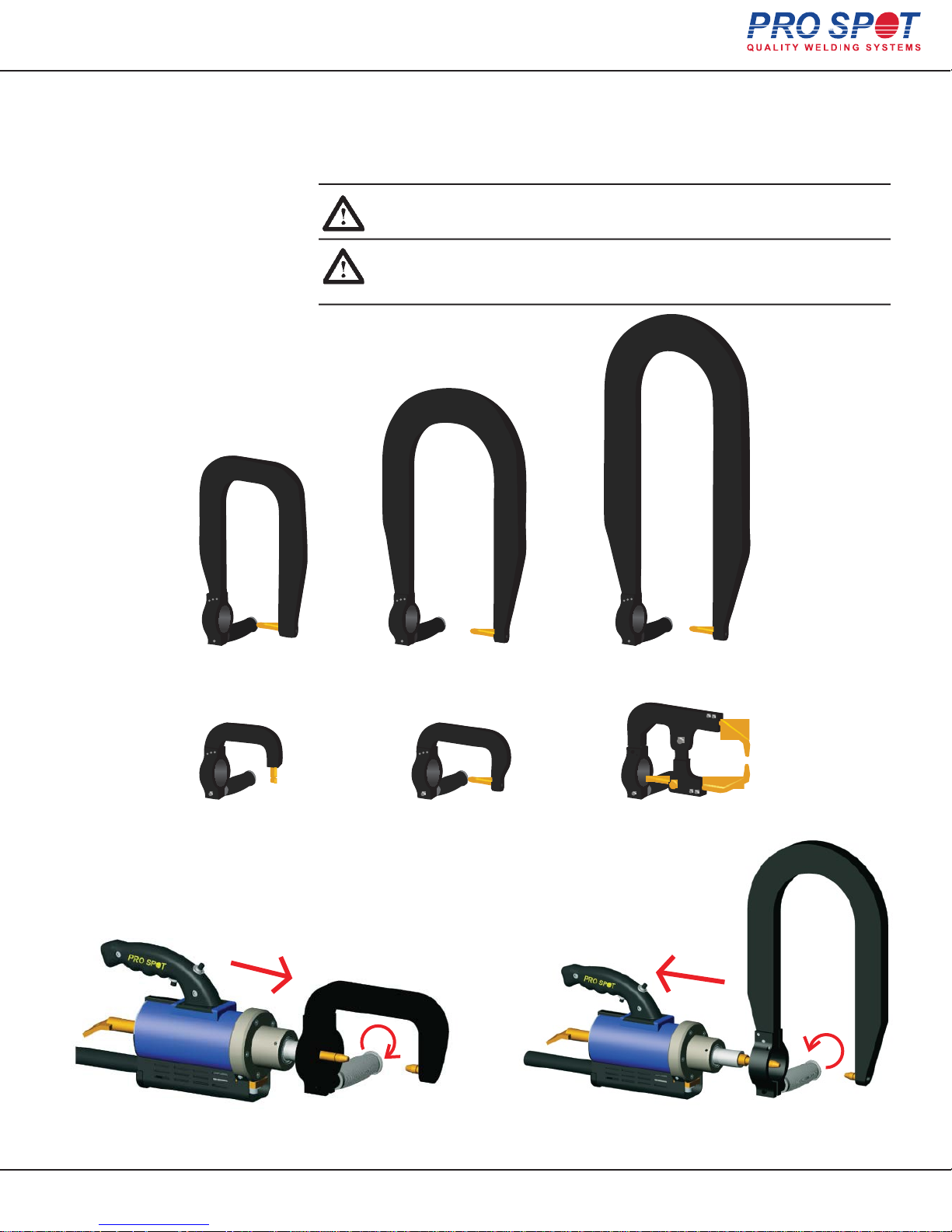
5.2 Extension Arms
Figure 5.2 Hybrid Spot Extension Arms
The Hybrid Spot comes with a variety of extension arms to accomodate any welding job situation.
Please refer to fig. 5.3 for details on what welding electrodes to use with each
extension arm.
NOTE: Extension arms marked “optional” are available from your local
distributor or online at www.prospot.com
REMARQUE: bras d'extension portant la mention «facultatif» sont
disponibles à partir de votre Distributeur régional ou en ligne à
www.prospot.com
PS-306
(optional)
PS-52
Wheelhouse Arm
5.2.1 Switching to extension arms
PS-305
508mm Extension Arm
PS-302 C-Arm PS-403 (optional)
PS-503-W
(optional)
C-X Adapter
Loosen the handle and pull off the C-arm... Now, insert the extension arm and tighten the handle.
All Info Copyright © Pro Spot International Inc.
5 Double-Sided Welding
Page 18
20
Page 21

Hybrid Spot
5.2.2 Extension Arms and Welding Electrodes
Different extension arms require the use of different welding electrodes.
Use charts in fig. 5.3 and 5.4 to determine the correct combination of extension
arms and welding electrodes.
IMPORTANT! Using incorrect welding electrodes with extension arms
may result in weak welds and/or damage to your welder.
IMPORTANT! En utilisant des électrodes de soudage inexactes au bras
d'extension peut donner des soudures faibles et / ou endommager votre
soudeur.
A
B C
A B C
PS-302 PS-1101-CM PS-103-CM
PS-52-5/8 PS-1101-CM PS-1133-5/8
PS-403 see Sec. 5.7.3 see Sec. 5.7.3
PS-305 PS-1101-CM PS-129-CM
PS-503-W PS-1101-CM PS-128-CM
Figure 5.3 Extension arm - Welding electrode configuration chart
Figure 5.4 Welding electrode selection chart
All Info Copyright © Pro Spot International Inc.
NOTE: PS-025 Welding Caps can be purchased in packages of 15 from
your local distributor or online at www.prospot.com
REMARQUE: PS-025 caps de soudure peuvent être achetés en paquets de 15
à partir de votre distributeur local ou en ligne à www.prospot.com
5 Double-Sided Welding
Page 19
21
Page 22
Hybrid Spot
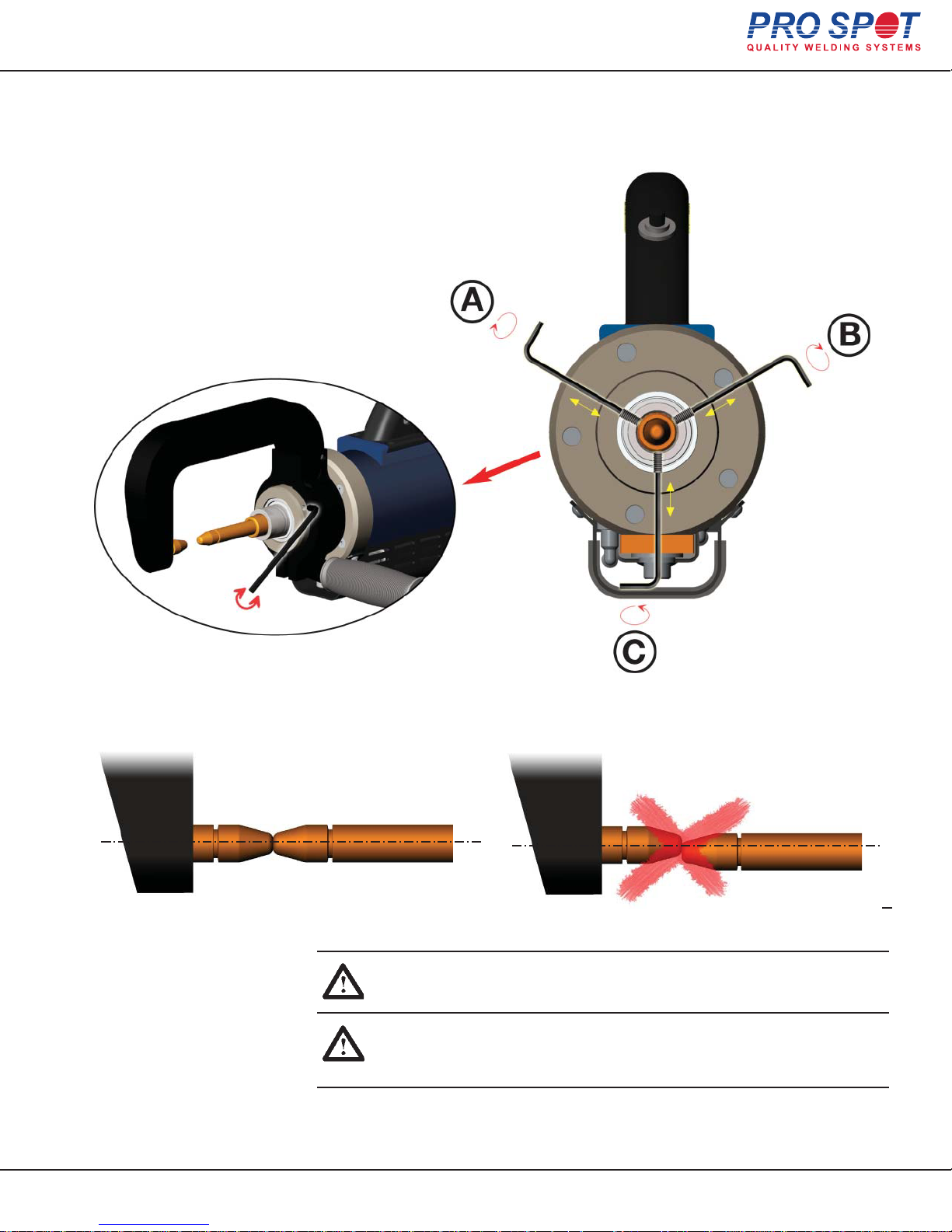
5.3 PS-500 Electrode Alignment
Use the set screws (A, B, C) to align the electrodes. Ex: to move electrode down,
loosen screw (C) and tighten screws (A and B).
Figure 5.5 Electrode Alignment
CORRECT
IMPORTANT! Always maintain proper electrode alignment. Not doing
so may result in weak, substandard welds!
IMPORTANT! Toujours maintenir l'alignement des électrodes appropriées. Ne pas le faire peut conduire aux soudures faibles de qualité
inférieure!
WRONG
All Info Copyright © Pro Spot International Inc.
5 Double-Sided Welding
Page 20
22
Page 23
Hybrid Spot
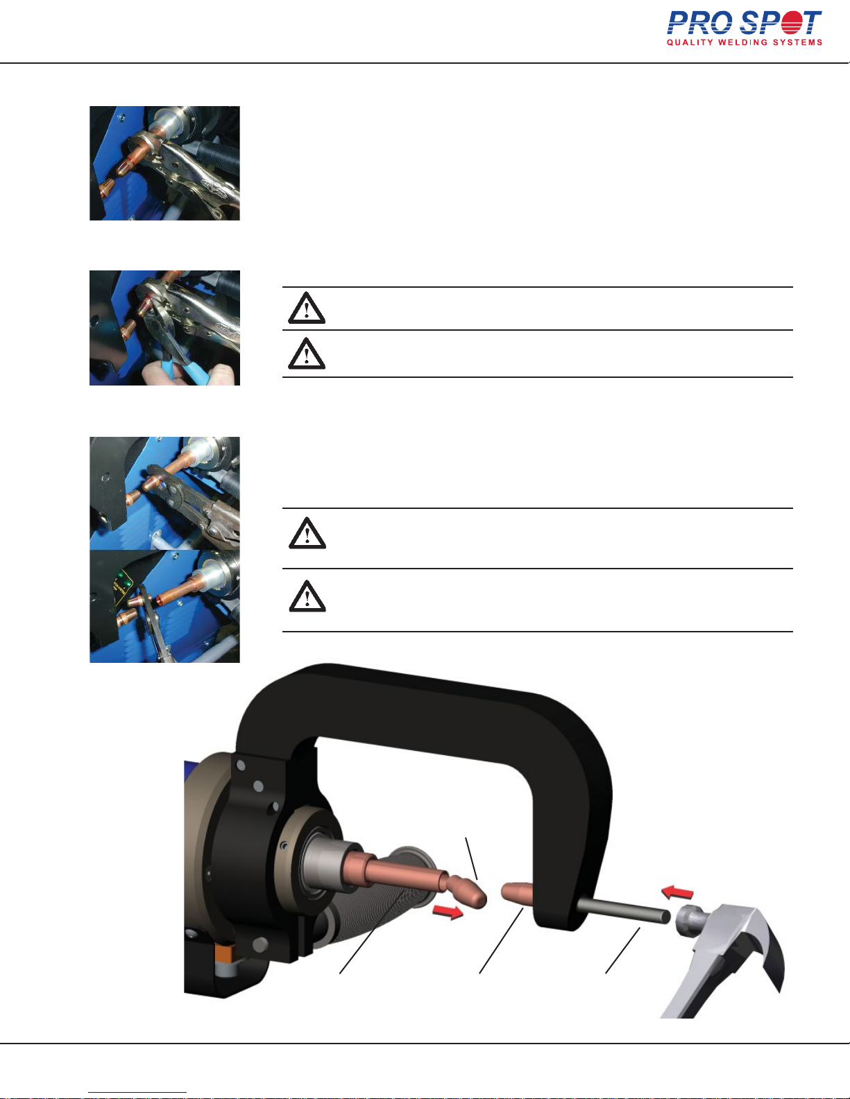
5.4 Removing Welding Electrodes
Removing Extension Arm Electrode
The extension arm electrodes can be easily removed by lightly tapping them
with a pin and hammer as shown in fig. 5.6
To remove the piston electrode:
Removing Piston Electrode
1. Grip piston electrode with a set of pliers or vise-grips (
2. Rock the pliers back and forth to loosen the electrode from the holder.
Figure 5.6a: Removing
Piston Electrode
3. Remove the electrode
Note: Vise-Grips shown in fig. 5.6a are specially designed to hold round
objects without damaging or scarring them. You can purchase a set from your
local distributor or online at: www.prospot.com
fig.5.6a
IMPORTANT! Do not attempt to remove the electrode by hitting it.
This could damage the electrode and the spot gun.
IMPORTANT! N'essayez pas de retirer l'électrode en la frappant.
Cela pourrait endommager l'électrode et le “pistolet”.
).
Figure 5.6b: Removing
Welding Cap
Figure 5.6c: Optional Weld
Cap Removal Tool
Removing Welding Caps
To remove a welding cap:
1. Hold piston electrode with a set of pliers or vise-grips.
2. Grip welding cap with another set of pliers or wedge side cutters between
cap and shank as shown in fig. 5.6b
3. Twist the two to loosen and remove the welding cap.
NOTE: An optional welding electrode cap removal tool is available,
which makes cap removal easy (fig. 5.6c). You can order the cap
removal tool from your local distributor or online at: www.prospot.com
NOTE: Une option d’un outil pour enlever le bouchon est disponible,
Pour faciliter le retrait du bouchon (fig. 5.6c). Vous pouvez commander
cet outil de votre distributeur local ou en ligne à l'adresse: www.prospot.com
Piston Electrode Extension Arm
All Info Copyright © Pro Spot International Inc.
Welding Cap
Electrode
Figure 5.6 Removing Welding Electrodes
5 Double-Sided Welding
Pin
Page 21
23
Page 24
Hybrid Spot
5.5 Welding Electrode Maintenance
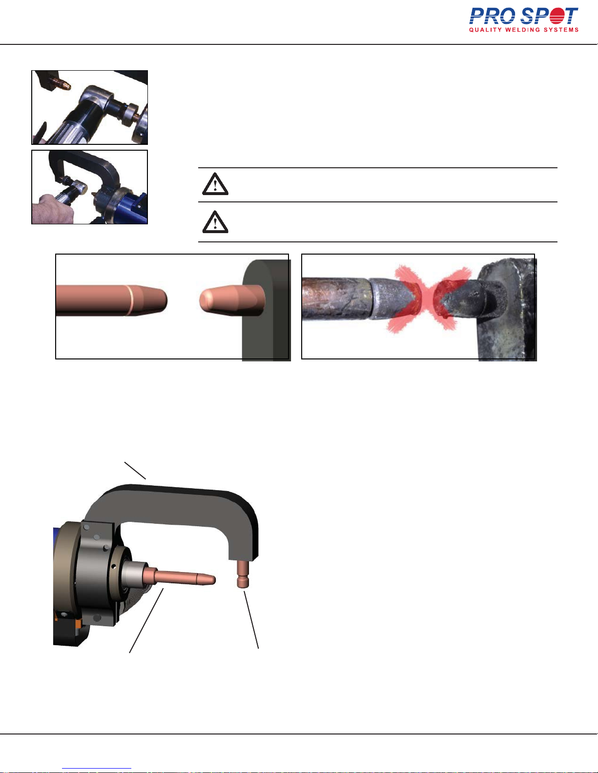
To maintain structurally-sound welds it is important to keep your welding
electrodes clear from build-up. It is also important to maintain a 6mm weld
nugget diameter. Clean electrodes with a file and periodically replace welding caps as explained in Section 5.4 “Removing Welding Electrodes”
Also Available: Pro Spot PLT-50/A Pneumatic Low Profile Dresser
sharpens your dull tips without having to remove the arm (Fig. 1).
Fig. 1
WARNING! The electrodes may be hot. Use caution when handling
them.
ATTENTION! Les électrodes peuvent être chauds. Soyez prudent
lors de leur manipulation.
5.6 Wheel House Arm
PS-52-5/8:
Wheel House Arm
PS-1101-CM:
60mm Electrode Shank
The wheel house adapter allows access to hard to reach areas such as
the wheel house
PS-1133-5/8:
Electrode
All Info Copyright © Pro Spot International Inc.
5 Double-Sided Welding
Page 22
24
Page 25
Hybrid Spot
5.7 X-Adapter (optional)
5.7.1 Attaching the X-Adapter
C-TYPE GUN
The advantage of the C-Type Spot Gun is that when making vertical pinch
welds on quarter panels, rocker panels, door pillars, etc., the spot gun is
positioned perpendicular to the work area. Easy to reach! Easy to use!
X-TYPE GUN
The X-type design is used on certain applications where the C-type can’t reach.
90% of all welding needs can be done with the C-type but for some radiator support and truck bed pinch welds, the X-Adapter works better. This new invention
makes it possible to weld where you never could before!
321
Loosen the handle and pull
out C-arm...
4
Insert the Tapered Electrode (B)
into the Shaft (C). Apply air
(carefully) to put pressure on the
electrodes so that Tapered
Electrode seats firmly in the shaft
before tightening the Collar (D)
set screw.
C
B
D
A
Follow instructions in Sec. 5.4
to remove piston electrode
Insert the X-Adapter onto the
gun.Tighten handle (A).
5
D
Tighten the Collar (D) set screw.
IMPORTANT! Do not tighten the Collar before the inserting Tapered
Electrode into the shaft. The collar is designed to prevent the Tapered
Electrode from falling out of the Shaft when the gun is fully opened.
All Info Copyright © Pro Spot International Inc.
IMPORTANT! Ne serrez pas le collier avant de glisser l’ Électrode
Rétreci dans le tube. Le collier est conçu pour empêcher l’ Électrode
Rétreci de tomber du tube quand le pistolet est complètement ouvert.
5 Double-Sided Welding
Page 23
25
Page 26
Hybrid Spot
5.7 X-Adapter (optional) cont.
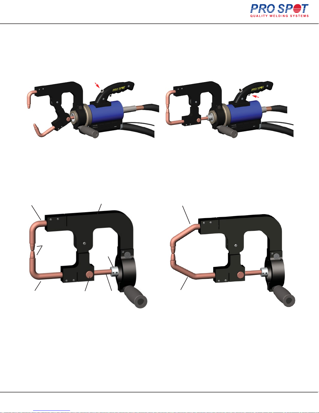
5.7.2 Using the X-Adapter
Push the upper switch to open electrodes wide. Push the lower switch to close electrodes and weld.
5.7.3 X-Adapter Configurations
90° Electrode - Upper
(PS-411)
PS-024
Welding Cap
90°Electrode - Lower
(PS-412)
Figure 5.7 90° Arm Set
Pivot Axle
(PS-406)
X Adapter
(PS-404)
Collar
(PS-407)
Tapered
Electrode
(PS-405)
45° Electrode - Upper
(PS-421)
45°Electrode - Lower
(PS-422)
Figure 5.8 45° Arm Set
All Info Copyright © Pro Spot International Inc.
5 Double-Sided Welding
Page 24
26
Page 27
Hybrid Spot
6 Single-Sided Welding
6.1 Single-Sided Welding Overview (Not recommended for structural welding, for cosmetic only.)
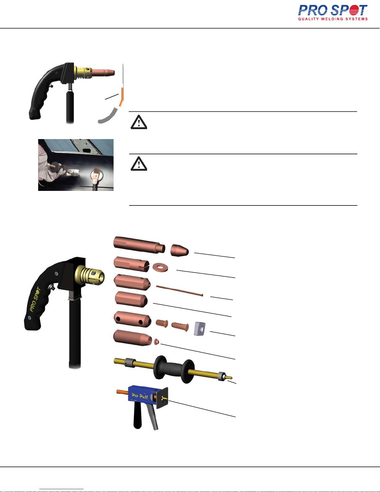
The Single-Sided Weld System allows the operator to carry out
welding tasks using a Single-Sided Weld Gun. The Single-Sided
weld procedure requires contact only from one side compared to
two sides in Two-Sided welding. A ground plate must be connected to the panel to be welded for it to work (fig. 6.1).
ground plate
Figure 6.1
Figure 6.1b
You can also use an optional magnetic ground plate to easily attach the ground
cable to the metal (fig. 6.1b
NOTE: Make sure the ground plate is clamped firmly in place on the
inside of a clean metal surface as near as possible to the weld location.
Do not attach the ground to the metal you're about to weld on. When
performing other weld tasks such as dent pulling, etc., the ground
attachment location becomes less critical.
REMARQUE: Assurez-vous que la plaque de terre est serré solidement en place à l'intérieur d'une surface métallique propre aussi près
que possible du lieu de soudure. Ne fixez pas le terre et le métal que
vous êtes sur le point de soudure . En accomplissant d'autres tâches
comme la soudure dent de traction, etc, le lieu de saisie devient
moins critique.
).
In the Single-Sided weld mode the following weld procedures are available for the
Hybrid Spot:
Single-Sided Welding (cosmetic repair only)
Washer Welding
Nail Welding
Contact Shrinking
Bolt and Nut Welding
Rivet Welding
Spot Hammer Dent Pulling
Figure 6.2 Single-Sided applications
All Info Copyright © Pro Spot International Inc.
6 Single-Sided Welding
Pro Pull Dent Removal
Page 25
27
Page 28

Hybrid Spot
Single Sided Welding Reference:
For single sided welding with the Hybrid Spot, it is important to not use too many batteries in
the ON position as the weld power will be too high.
Start with 1 battery in the ON position and the lowest weld time.
For dent pulling use 1 battery and the lowest time setting available. If less power is needed,
try to separate the ground cable further away from the weld area to create more power
resistance and/or use the pointed spot hammer tip to spread out the heat zone.
All Info Copyright © Pro Spot International Inc.
6 Single-Sided Welding
Page 26
28
Page 29
Hybrid Spot
6.2 Single-Sided Spot Welding
Figure 6.9
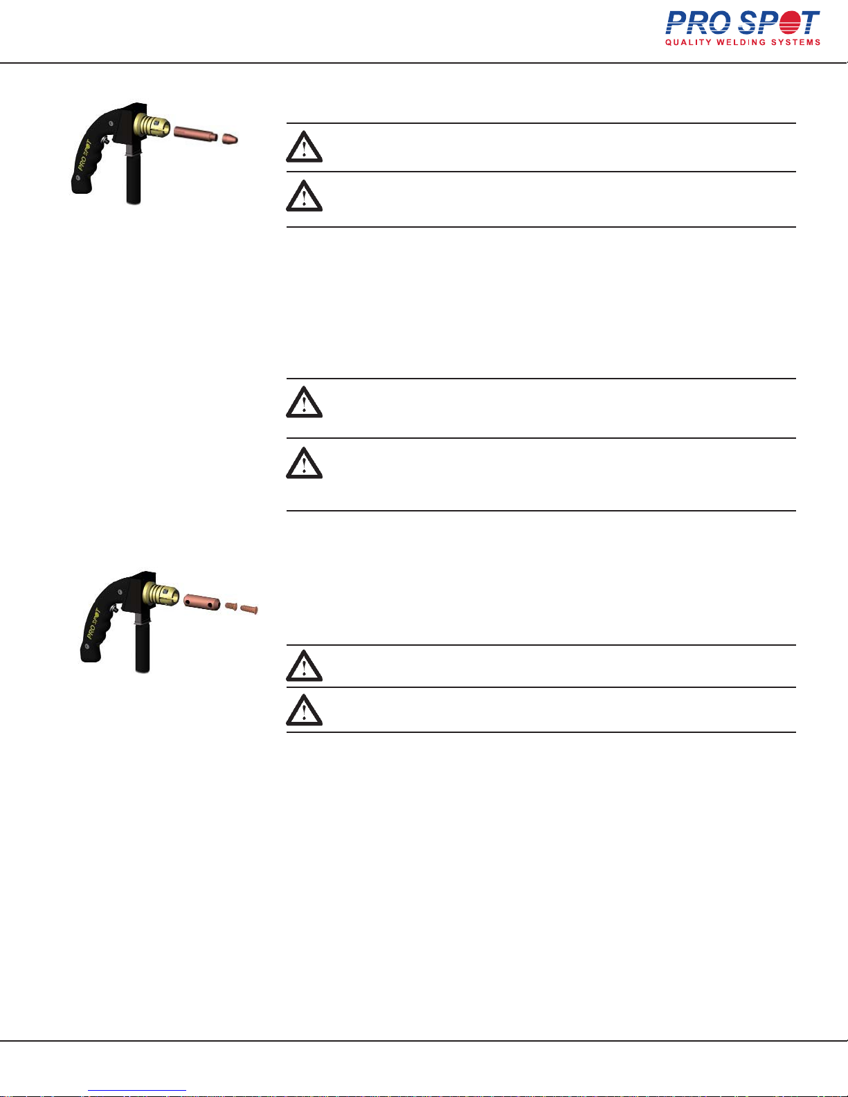
Single-Sided spot welding is used where Two-Sided spot welding cannot be used.
Important: The Single-Sided spot welding is not permitted on supporting
frameworks of a vehicle. It is only permitted for cosmetic purposes.
Important: Le soudage de Côté Unique par points n'est pas autorisée sur
les cadres de soutien d'un véhicule. Il est seulement permis à des fins
cosmétiques.
1. Select 1-4 Batteries in the ON position.
2. Fit the Single-Sided Gun with Single-Sided electrode (fig.6.9).
3. Grind between the inner and the outer body sheets to remove paint, primer and
rust. This ensures good electrical contact when performing Single-Sided welding.
4. Ground the working area (refer to section 6.1 "Single-Sided Welding
Overview").
5. Apply about 33-44 lbs of pressure on the Single-Sided gun and push the trigger
to weld. Reposition and weld again.
Note: Make sure that Single-Sided electrode is clean. If it isn't, use a file
or tip dresser to clean it. If the weld cap shows considerable wear, it
should be replaced (refer to section 5.4 “Removing Welding Electrodes”)
6.3 Bolt Welding
Figure 6.12
Remarque: Assurez-vous que l ‘électrode Côté Unique est propre. Si
ce n'est pas, utilisez une lime pour le nettoyer. Si le bouchon de
soudure est considerablement usé, il devrait être remplacé (voir la
section 5.4 "Enlèvement d’Electrodes de soudage»)
Many of today's car bodies come with factory equipped threaded studs. After a collision,
the studs may be lost or do not accompany the replacement part. Withthe Hybrid Spot,
threaded studs can be welded-on in factory style. This type of stud is alsocommon
throughout the car body for attachments of interior, tail lights, door mold-ings, etc.
Tip: A threaded stud can also be used to fasten the ground clamp directly
to the panel, minimizing the area needed for grinding.
Astuce: Un goujon fileté peut également être utilisé pour fixer la pince
directement sur le panneau, ce qui réduit la surface nécessaire au broyage.
Studs are held in place during welding with magnetic adapter electrode.
1. Select 1-2 Batteries in the ON position.
2. Fit Single Sided gun with the magnetic stud adapter (fig. 6.12
3. Insert stud into the adapter (fig. 6.12).
4. Prepare the surface area by removing paint and primer.
5. Ground the working area (refer to section 6.1 "Single-Sided Welding
Overview").
6. Position single sided gun over work area and push the trigger to weld.
7. Repeat as needed.
).
All Info Copyright © Pro Spot International Inc.
6 Single-Sided Welding
Page 27
29
Page 30
Hybrid Spot
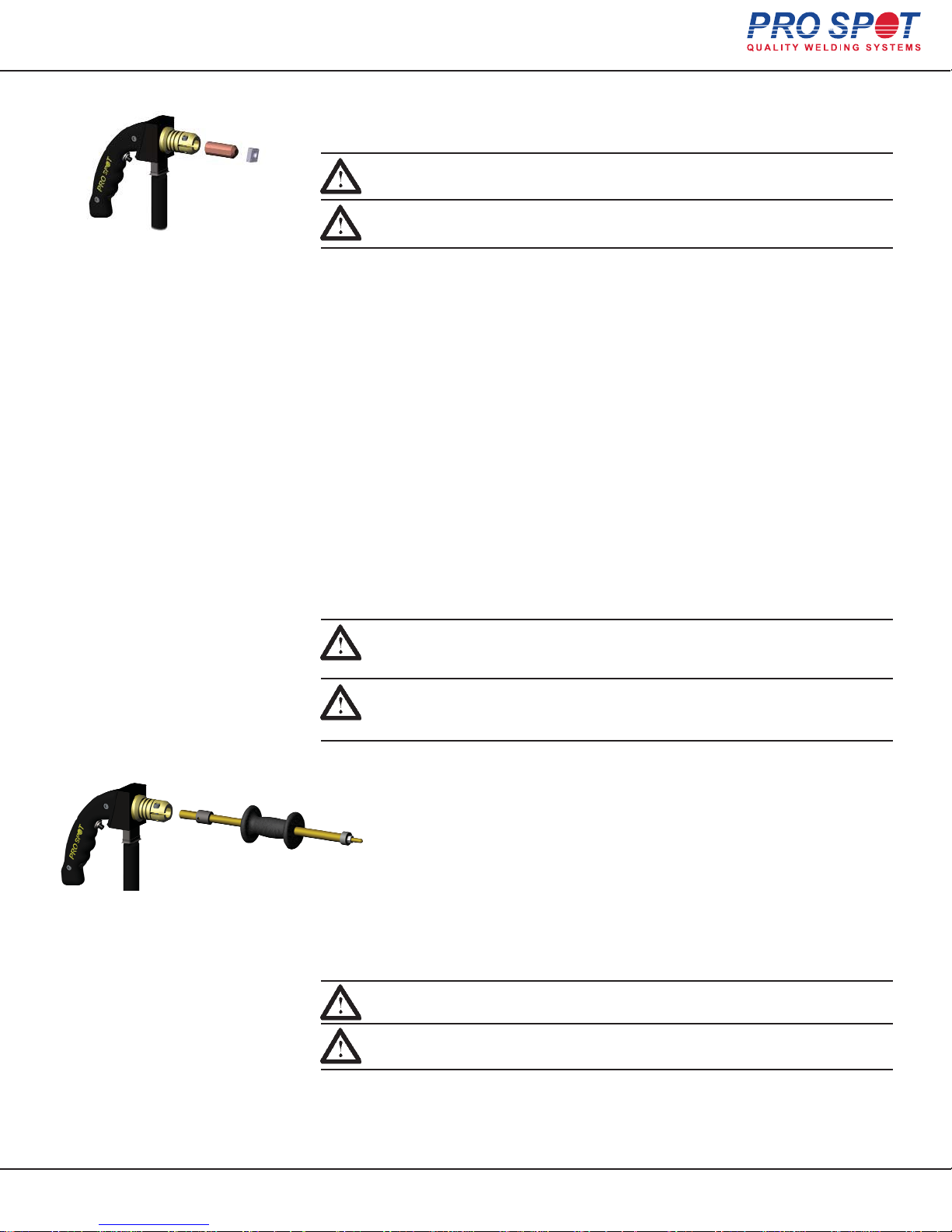
6.4 Nut Welding
Weld-on nuts are common throughout the car body for attachments of interior, tail
lights, door moldings, etc. and are applied with ease using the Hybrid Spot.
Tip: Different size nuts are available from your local Pro Spot distributor
or on the web at Pro Spot online store.
Astuce: noix de différentes tailles sont disponibles chez votre distributeur local Spot Pro ou sur le web à la boutique Pro Spot en ligne.
Figure 6.15
Nuts are held in place during welding with a shrinking electrode.
1. Select 1-2 Batteries in the ON position.
2. Fit Single-Sided gun with the Shrink Electrode (fig. 6.15).
3. Prepare the surface area by removing paint and primer.
4. Ground the working area (refer to section 6.1 "Single-Sided Welding
Overview").
5. Press weld-on nut to the metal with Contact Shrinking electrode, apply some
pressure and push the trigger to weld.
6. Repeat as needed.
6.5 Dent Pulling with Spot Hammer
Spot hammer dent pulling is used to repair dents on a vehicle body. The spot
hammer welds directly onto the work area and pulls the dent.
Tip: The replaceable welding tip should last for over one thousand welds.
Contact your local distributor to order replacement tips, or order on the
web at Pro Spot online store.
Astuce: Le bout de soudage remplaçable devrait durer plus d'un millier
soudures. Contactez votre distributeur local pour commander pointes de
rechange, ou commandez sur la Web Pro Spot au magasin en ligne.
1. Select 1 Battery in the ON position.
2. Fit Single-Sided gun with the spot hammer (fig. 6.18).
3. Prepare the dent surface area by removing paint and primer.
4. Ground the working area (refer to section 6.1 "Single-Sided Welding
Overview").
5. Position the spot hammer tip at the bottom of the dent and push the
trigger to weld the electrode onto the metal.
6. Pull out a dent then release by twisting the hammer.
Figure 6.18
7. If needed, reposition, weld, and pull again.
Note: Check spot hammer tip periodically to make sure it is in good
working order. If the tip looks worn, replace it with a new one.
All Info Copyright © Pro Spot International Inc.
Note: Contrôlez le bout marteau périodiquement pour s'assurer qu'il est en
bon état de marche. Si le bout semble usé, le remplacer par un nouveau.
6 Single-Sided Welding
Page 28
30
Page 31
Hybrid Spot
6.6 Moulding Clip Rivet Welding
This function will weld on factory type clips for the window moulding. The clips
that hold the moulding do not, usually, come on the replacement parts.
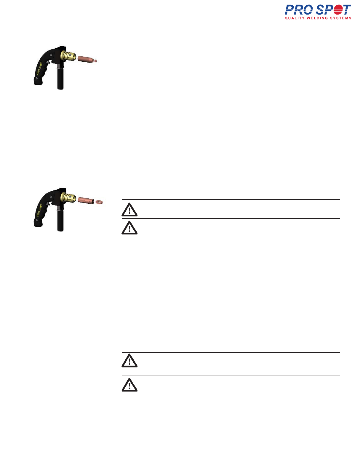
Rivets are held in place during welding with magnetic adapter electrode.
1. Select 1 Battery in the ON position, minimum weld time.
2. Select Rivet Welding Program by pressing the Left or Right Navigation Buttons
3. Choose weld power level by pressing the “Next Program” button repeatedly.
Figure 6.21
4. Fit Single-Sided gun with the magnetic rivet adapter (fig. 6.21).
5. Insert rivet into the adapter (fig. 6.21).
6. Prepare the surface area by removing paint and primer.
7. Ground the working area (refer to section 6.1 "Single-Sided Welding
Overview").
8. Position Single-Sided gun over work area and push the trigger to weld.
9. Repeat as needed.
6.7 Dent Pulling with Washers and Slide Hammer with Hook
The slide hammer with hook (optional) can be used in conjunction with washers
to repair car body dents.
Figure 6.24
Tip: You can purchase a slide hammer with hook from your local Pro Spot
distributor or on the web at Pro Spot online store.
Astuce: Vous pouvez acheter un marteau glissant avec crochet de votre
distributeur locale Pro Spot ou sur le web à la boutique Pro Spot en ligne.
Washers are held in place during welding with magnetic adapter electrode.
1. Select 1 Battery in the ON position.
2. Fit Single-Sided gun with the magnetic washer adapter (fig. 6.24).
3. Insert washer into the adapter (fig. 6.24).
4. Prepare the dent surface area by removing paint and primer.
When welding on washers, you only need to clean the area where the washer
touches the metal since the grounding system is connected through a separate
cable.
5. Ground the working area (refer to section 6.1 "Single-Sided Welding
Overview").
6. Position the washer at the bottom of the dent and push the trigger to weld the
washer onto the metal.
7. Hook the washer with the slide hammer and pull out the dent.
8. Repeat as needed.
Tip: You can, also, pull multiple washers by welding on a row of washers
at the bottom of the dent, inserting a rod through the washers and pulling
the rod with the slide hammer with hook.
Astuce: Vous pouvez, également, tirer plusieurs rondelles par soudage sur
une rangée de rondelles au bas de la Dent, insertant une baguette par les
rondelles et en tirant la tige avec le marteau glissqnt avec crochet.
All Info Copyright © Pro Spot International Inc.
6 Single-Sided Welding
Page 29
31
Page 32
Hybrid Spot
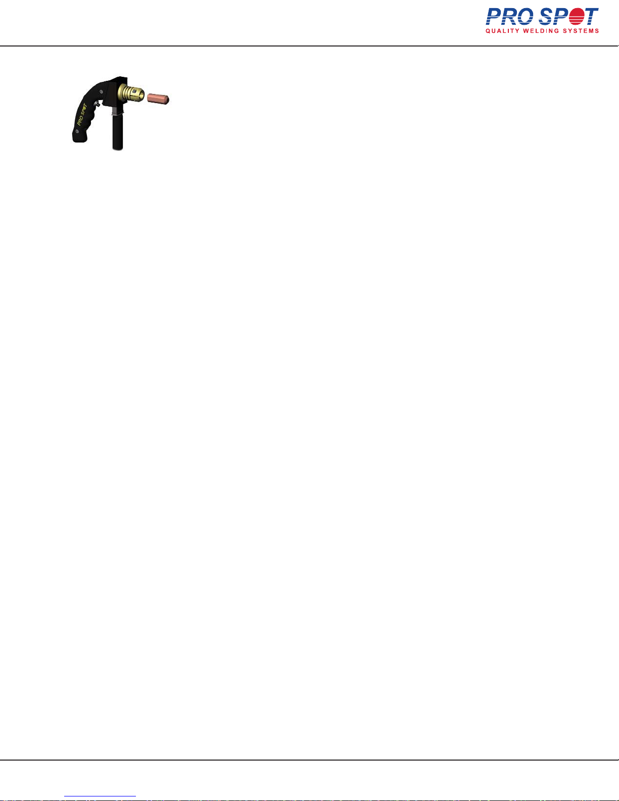
6.8 Contact Shrinking
Dent pulling with washers creates high spots in the metal. Until now, the common
practice would have been to grind the surface, resulting in a loss of sheet metal
thickness. With the Hybrid Spot, use the shrinking tip instead of a grinder to remove the
high spots, leaving a smooth and clean surface that's every bit as thick and
strong as before. Shrinking electrode also acts as a nut adapter (refer to section
6.4 "Nut Welding"). With this electrode you get two convenient tools in one.
Figure 6.27
1. Select 2 Batteries in the ON position.
2. Fit Single-Sided gun with the contact shrinking electrode (fig. 6.27).
3. Prepare the surface area by removing paint and primer.
4. Ground the working area (refer to section 6.1 "Single-Sided Welding
Overview").
5. Position the contact shrinking electrode over the high spot, apply some pressure and push the trigger to weld.
6. Repeat as needed.
All Info Copyright © Pro Spot International Inc.
6 Single-Sided Welding
Page 30
32
Page 33
Hybrid Spot
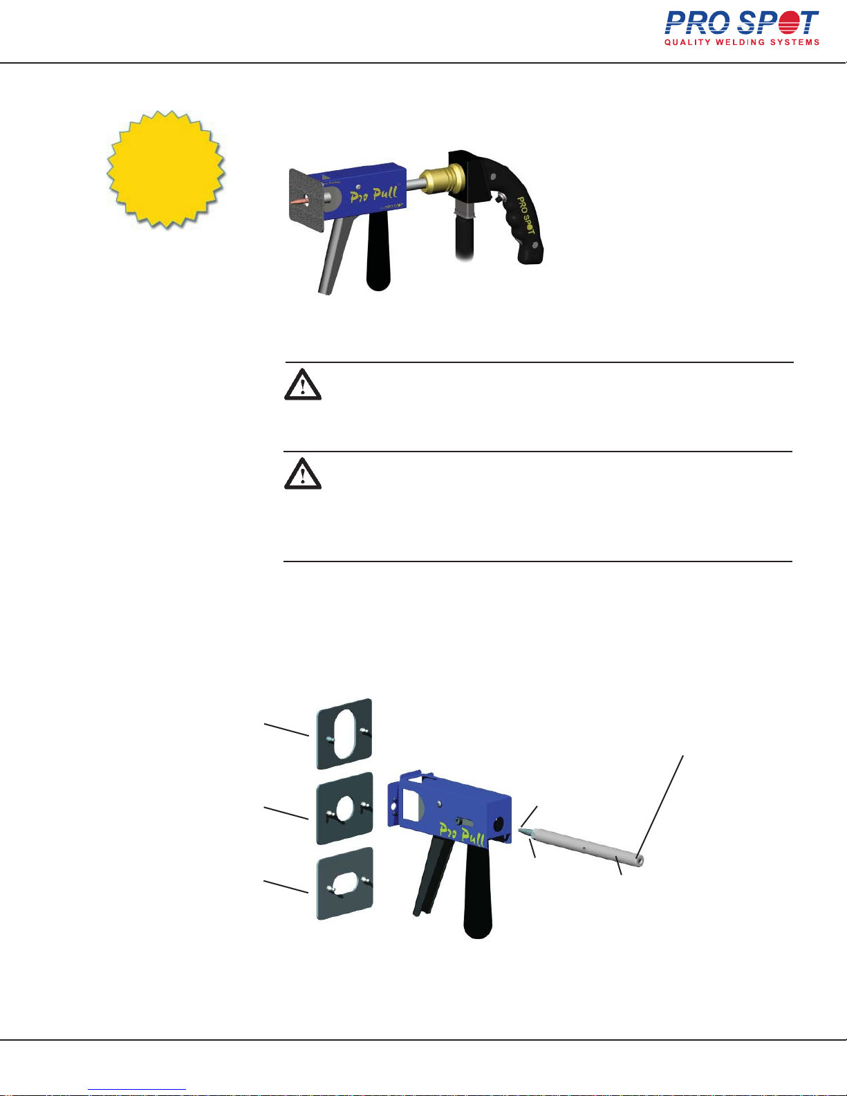
6.9 Pro Pull Dent Pulling (optional)
Pro Pull is a patented, innovative tool for fast and accurate dent pulling. It
features paintless dent removal functionality (see sec. 6.3.5 “Paintless Dent
Pro Pull can be
fitted to most
resistance spot welders
or dent pullers.
Welder & Adapters
not included.
Pulling With Pro Pull”).
6.9.1 Selecting Pro Pull Weld Mode
Make sure the ground plate is clamped firmly in place on the inside of a
clean metal surface as near as possible to the weld location.
NOTE: Do not attach the ground to the metal you're about to weld on.
When performing other weld tasks such as dent pulling, etc., the ground
attachment location becomes less critical.
Assurez-vous que la plaque de terre est serré fermement en place à
l'intérieur d'une surface propre de métal le plus près que possible au lieu
de soudure.
NOTE: Ne fixez pas le terre et le métal que vous êtes sur le point de
soudre. Lors de l'exécution d'autres tâches comme la soudure dent de
traction, etc, le terre du lieu de saisie devient moins critique.
6.9.2 Pro Pull Component Diagram
Pro Pull comes with three different
Blocking Plates with Quick-Connect design.
Block window size:
2.5"(63mm) x 1.5"(38mm)
PP-10-04
Block window size:
1.75"(44mm) x 1"(25mm)
PP-10-03
Block window size:
0.75" (19mm) dia.
PP-10-01
Large openings for
great visual control
of the pulling area.
CLT-55
Electrode
N-38
Nut
Retrofit point for different end adapters.
Available for most weld guns.
(not included) See prospot.com for more
information.
CLP-75
Removable weld shaft.
The weld current is
transferred through the shaft
and NO CABLE is required
to transfer the current
All Info Copyright © Pro Spot International Inc.
6 Single-Sided Welding
Page 31
33
Page 34
Hybrid Spot
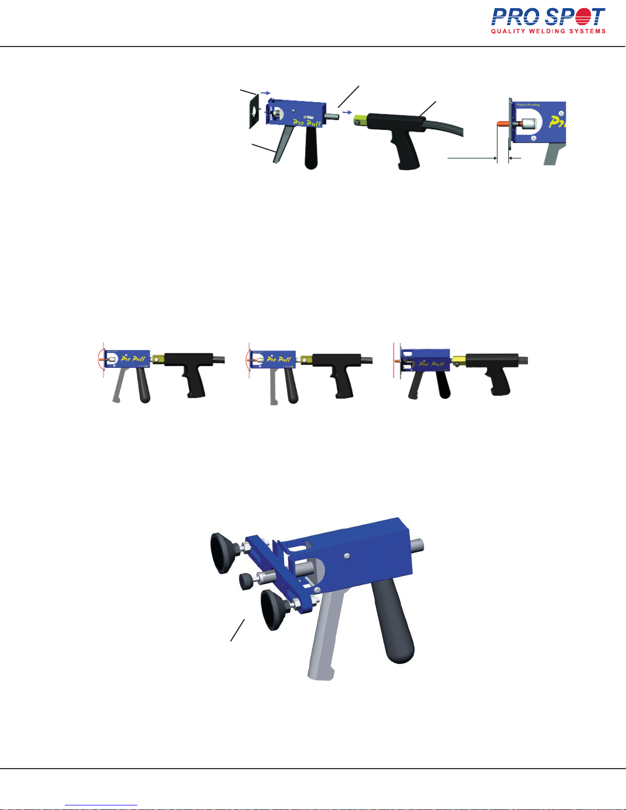
6.9.3 Pro Pull Assembly
C
A
D
1. Attach the Weld Gun (D) to Weld Shaft (C). Secure Lock Bolt (G).
2. Slide weld shaft and gun to standard distance (E).
3. Attach desired block plate (A)
4. Position the weld tip in the “bottom” of the dent, weld, then pull the handle (F)
to initiate the pulling action. Use the shortest weld TIME possible to prevent
extensive weld marks.
6.9.4 Dent Pulling with Pro Pull
1 2 3
Aim, position & fire! Pull dent with Auto
F
Blocking.
approx.
0.7”(17mm)
E
Twist gun to release tip.
6.9.5 Paintless Dent Pulling With Pro Pull
Glue Adapter for Paintless
Dent Removal
All Info Copyright © Pro Spot International Inc.
6 Single-Sided Welding
Page 32
34
Page 35
Hybrid Spot
7 Troubleshooting
1. The display says “Low Voltage” on Batt1 display line.
This indicates that Battery 2’s voltage line reached the minimum safe operating voltage and has been disabled. The
battery is not available for welding and is being charged automatically (if welder is plugged in). An alarm will sound
when attempting to weld if “Low Voltage” alert is displayed. To clear “Low Voltage” alert and continue welding with
remaining batteries, turn off the switch (Batt2 in this example) and welding can continue. When Battery 2 reaches
13.8V it will be available to use again when the switch is turned on.
IMPORTANT: Do not leave the batteries in a discharged condition. Charge Immediately.
2. The display shows “SERVICE” on Batt 3 display line
This alert indicates that the battery voltage has fallen below 11.5V and the battery needs to be replaced (Fig. 3). The
charger will not attempt to charge a battery that has discharged this low, as doing so might cause the battery or
charger to overheat.
3. The display says “Check Battery Water Levels”
This indicates that it is time to perform a battery water level check (see section 4.3.4). This alert is triggered based
on accumulative battery charge time. It is extremely important to maintain correct water levels. Failure to do so will
result in failure of batteries and warranty is voided.
4. Low weld power & Batteries not charging; Fan is not on, but otherwise the
welder appears normal.
- Check power cable for voltage reading.
- Check small breakers on back of panel, the breakers are resettable by pushing the breaker.
5. The gun is closing the weld tips but not welding.
- Make sure the weld switch is in weld mode and not in Batt test mode.
- Battery switches off?
- Batteries may be in disabled mode due to a “Low Voltage Condition” See low voltage alert.
6. Single Sided gun trigger does not work or seems intermittent.
The welder is programmed with 5 sec delay between welds to conserve power and prevent overheating.
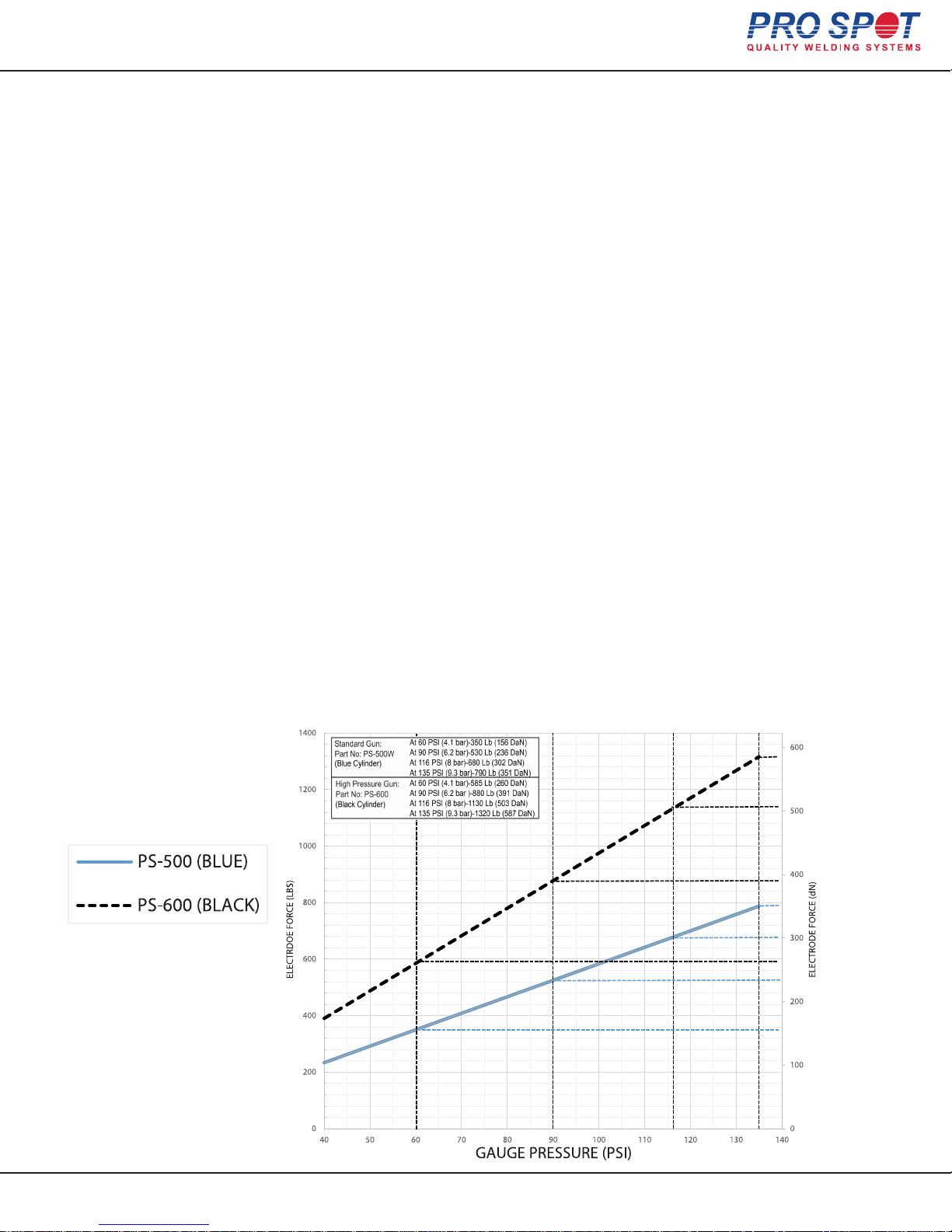
Electrode Squeeze Force vs Gauge Pressure
All Info Copyright © Pro Spot International Inc.
7 Troubleshooting
Page 33
35
Page 36

Pro Spot International, Inc.
5932 Sea Otter Place
Carlsbad, CA 92010
Toll Free: (877) PRO SPOT
Fax: (760) 407-1414
E-mail: [email protected]
Web: www.prospot.com
 Loading...