

Page 1

5707-21128-047-0S
Page 2
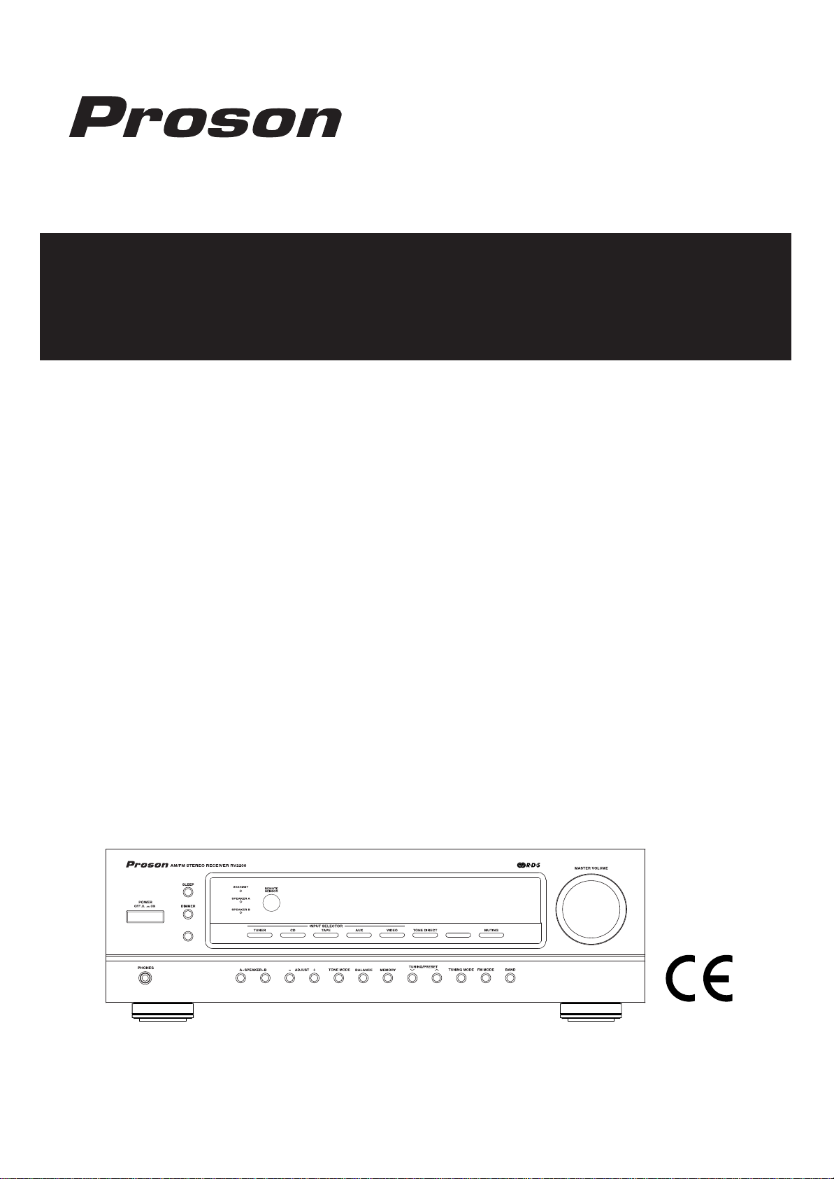
OWNER’S MANUAL
RV 2200
AM/FM Stereo Receiver
Page 3
2
Introduction
Congratulations on Your Purchase!
Your new high fidelity receiver is designed to deliver maximum enjoyment and years of trouble free service.
Please take a few moments to read this manual thoroughly. It will explain the features and operation of your
unit and help ensure a trouble free installation.
Please unpack your unit carefully. We recommend that
you save the carton and packing material. They will be
helpful if you ever need to move your unit and may be
required if you ever need to return it for service. Your unit
is designed to be placed in a horizontal position and it is
important to allow at least two inches of space behind
your unit for adequate ventilation and cabling convenience.
To avoid damage, never place the unit near radiators, in
front of heating vents, in direct sunlight, or in excessively
humid or dusty locations. Connect your complementary
components as illustrated in the following section.
CAUTION : TO REDUCE THE RISK OF
ELECTRIC SHOCK, DO NOT
REMOVE COVER (OR BACK).
NO USER-SERVICEABLE PARTS
INSIDE. REFER SERVICING TO
QUALIFIED SERVICE PERSONNEL.
CAUTION
RISK OF ELECTRIC SHOCK
DO NOT OPEN
This symbol is intended to alert the user to the
presence of uninsulated "dangerous voltage"
within the product's enclosure that may be of
sufficient magnitude to constitute a risk of
electric shock to persons.
This symbol is intended to alert the user to the
presence of important operating and maintenance (servicing) instructions in the literature
accompanying the appliance.
To reduce the risk of fire or electric shock, do not expose
this appliance to rain or moisture.
Caution : Do not block ventilation openings or stack
other equipment on the top.
FOR U.S.A.
Note to CATV System Installer: This reminder is
provided to call the CATV system installer's attention
to Article 820-40 of the NEC that provides guidelines
for proper grounding and, in particular, specifies that
the cable ground shall be connected to the grounding system of the building, as close to the point of
cable entry as practical.
FCC INFORMATION
This equipment has been tested and found to comply with the limits for a Class B digital device, pursuant to Part 15 of the FCC Rules. These limits are
designed to provide reasonable protection against
harmful interference in a residential installation. This
equipment generates, uses and can radiate radio
frequency energy and, if not installed and used in
accordance with the instructions, may cause harmful
interference to radio communications. However,
there is no guarantee that interference will not occur
in a particular installation. If this equipment does
cause harmful interference to radio or television
reception, which can be determined by turning the
equipment off and on, the user is encouraged to try
to correct the interference by one or more of the following measures:
Reorient or relocate the receiving antenna.
Increase the separation between the equipment
and receiver.
Connect the equipment into an outlet on a circuit
different from that to which the receiver is con-
nected.
Consult the dealer or an experienced radio/TV
technician for help.
CAUTION: Any changes or modifications in con-
struction of this device which are not expressly
approved by the party responsible for compliance
could void the user's authority to operate the equipment.
WARNING
UNP ACKING AND INST ALLATION
Caution regarding placement
(Except for U.S.A. and Canada)
To maintain proper ventilation, be sure to
leave a space around the unit (from the
largest outer dimensions including projections)
equal to, or greater than, shown below.
Left and right panels: 10 cm
Rear panel: 10 cm
Top panel: 50 cm
Page 4
FOR U.S.A AND CANADA 120 V
Units shipped to the U.S.A and Canada are designed
for operation on 120 V AC only.
Safety precaution with use of a polarized AC plug.
However, some products may be supplied with a
nonpolarized plug.
CAUTION : To prevent electric shock, match wide
blade of plug to wide slot, fully insert.
FOR YOUR SAFETY
FOR CHINA, EUROPE AND AUSTRALIA ........ 220V/230V/240V
Units shipped to China are designed for operation on
220 V AC only.
Units shipped to Australia are designed for operation
on 240 V AC only.
To ensure safe operation, the three-pin plug supplied
must be inserted only into a standard three-pin
power point which is effectively earthed through the
normal household wiring. Extension cords used with
the equipment must be three-core and be correctly
wired to provide connection to earth.
Improper extension cords are a major cause of fatalities. The fact that the equipment operates satisfactorily does not imply that the power point is earthed
and that the installation is completely safe. For your
safety, if in any doubt about the effective earthing of
the power point, consult a qualified electrician.
PAN-EUROPEAN UNIFIED VOLTAGE
All units are suitable for use on supplies 230-240 V
AC.
FOR YOUR SAFETY
3
READ THIS BEFORE OPERA TING YOUR UNIT
FOR OTHER COUNTRIES........................ 115 V/230 V
Units shipped to countries other than the above
countries are equipped with an AC voltage
selector switch on the rear panel. Refer to the
following paragraph for the proper setting of
this switch.
AC VOLTAGE SELECTION
This unit operates on 115/230 V AC. The AC voltage
selector switch on the rear panel is set to the voltage
that prevails in the area to which the unit is shipped.
Before connecting the power cord to your AC outlet,
make sure that the setting position of this switch
matches your line voltage. If not, it must be set to
your voltage in accordance with the following direction.
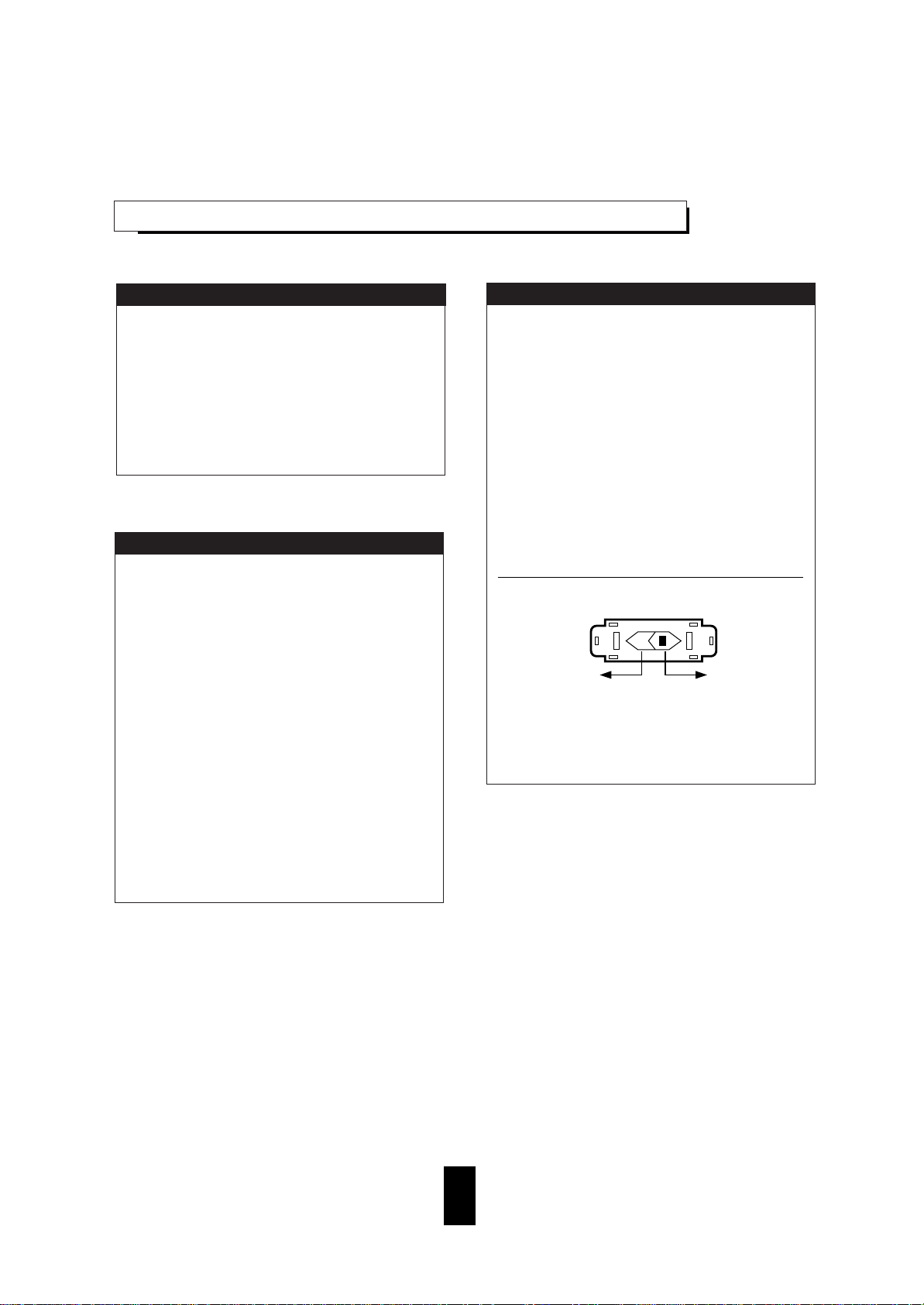
AC voltage selector switch
Move switch lever to match your line voltage with a
small screwdriver or other pointed tool.
FOR YOUR SAFETY
230 V~ 115 V~
Page 5

4
CONTENTS
Introduction
UNPACKING AND INSTALLATION ...............................................................................................2
READ THIS BEFORE OPERATING YOUR UNIT ......................................................................... 3
System Connections .......................................................................................................................5
Front Panel & Remote Controls .................................................................................................. 7
REMOTE CONTROL OPERATION RANGE ................................................................................ 9
LOADING BATTERIES ................................................................................................................. 9
Operations
LISTENING TO A PROGRAM SOURCE ..................................................................................... 10
LISTENING TO RADIO BROADCASTS ...................................................................................... 12
LISTENING TO RDS BROADCASTS(FM ONLY) ........................................................................ 14
RECORDING ................................................................................................................................. 15
OTHER FUNCTIONS ................................................................................................................... 16
Troubleshooting Guide ................................................................................................................. 17
Specifications .................................................................................................................................. 18
Page 6
5
System Connections
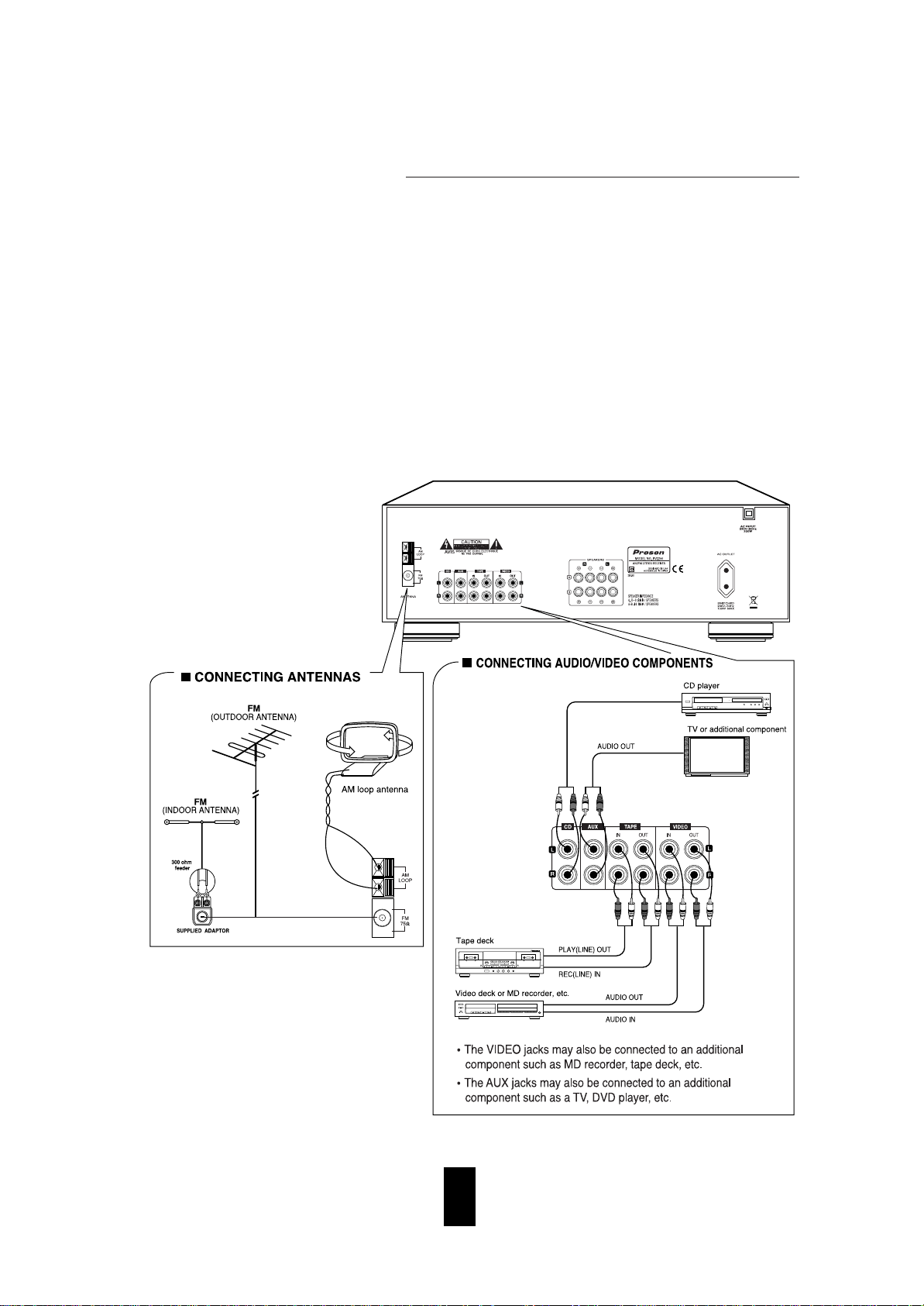
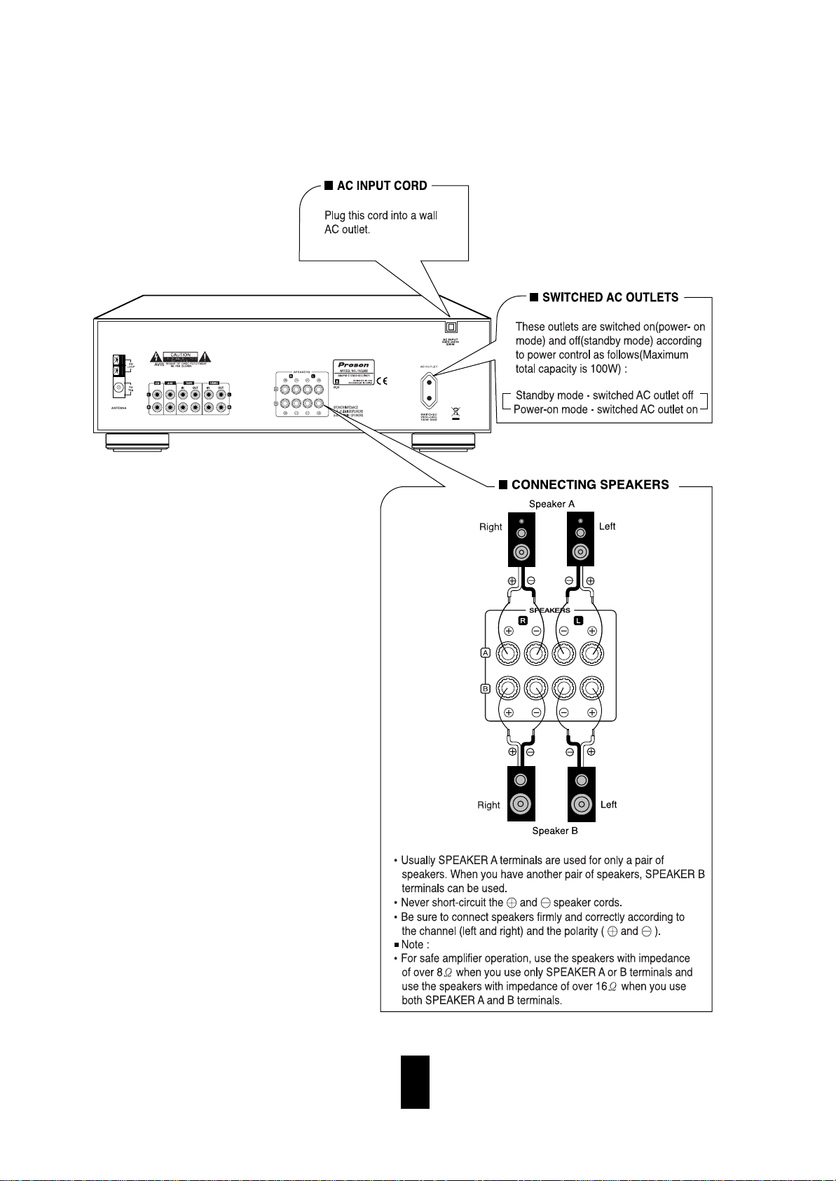
• Do not plug the AC input cord into the wall AC outlet until all connections are completed.
• Be sure to connect the white RCA pin cords to the L(left) and the red RCA pin cords to the R(right) jacks when
making audio connections.
• Change the position of the FM indoor antenna until you get the best reception of your favorite FM stations.
• A 75 outdoor FM antenna may be used to further improve the reception.
Disconnect the indoor antenna before replacing it with the outdoor one.
• Place the AM loop antenna as far as possible from the receiver, TV set, speaker cords and the AC input cord and
set it to a direction for the best reception.
• If the reception is poor with the AM loop antenna, an AM outdoor antenna can be used in place of the AM loop
antenna.
• Make connections firmly and correctly. If not, it can cause loss of sound, noise or damage to the receiver.
• If the electricity fails or the AC input cord is left unplugged for more than several days, the memorized contents
will be cleared.
Should this happen, memorize them again.
Page 7
6
Page 8
7
Front Panel & Remote Controls
Page 9
8
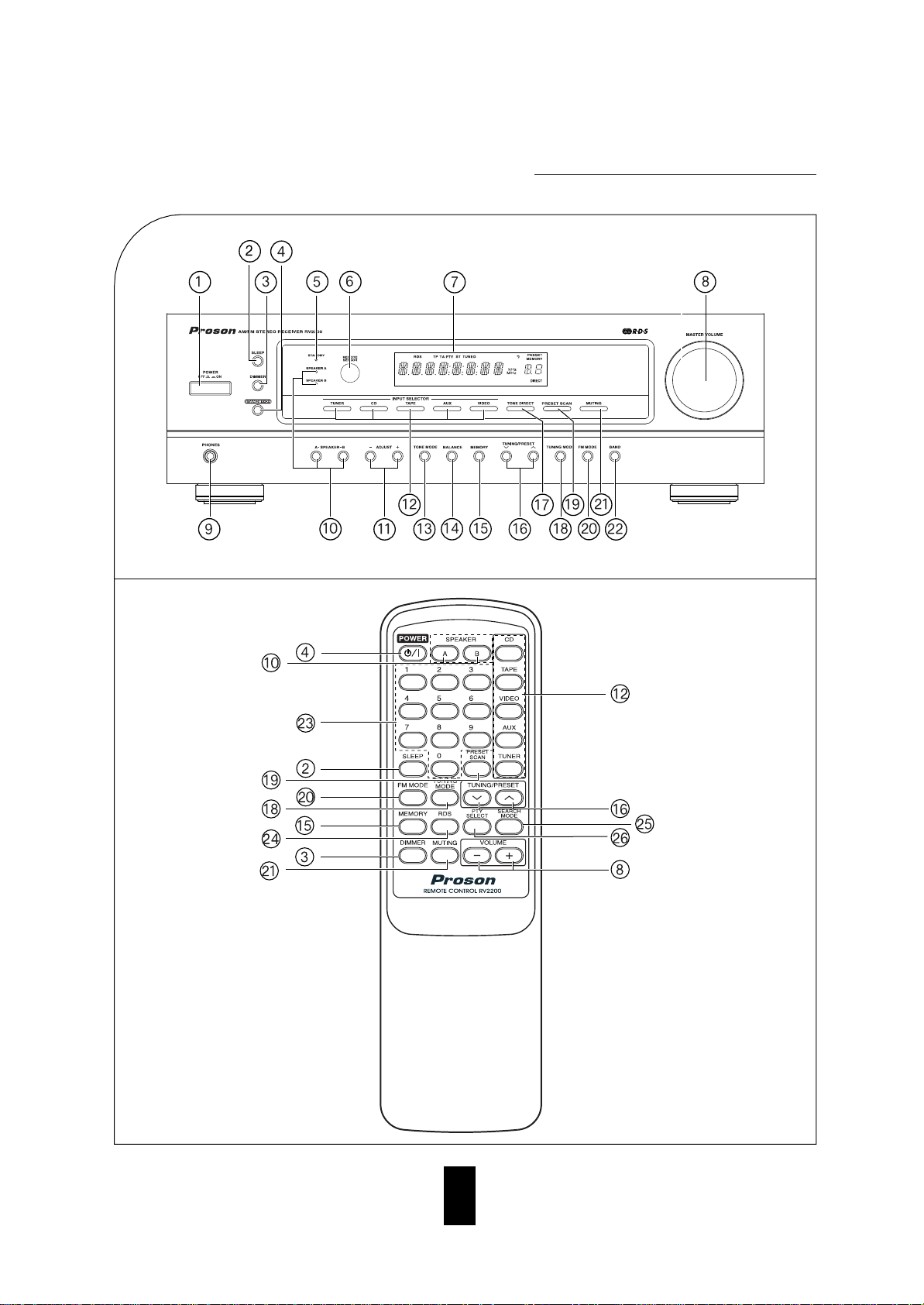
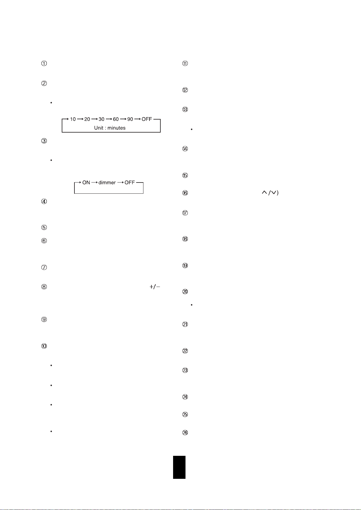
STANDBY/ON BUTTON
In the operating mode, when this button is pressed,
the unit is turned off to enter the standby mode.
STANDBY INDICATOR
REMOTE SENSOR
This receives the signals from the remote control
unit.
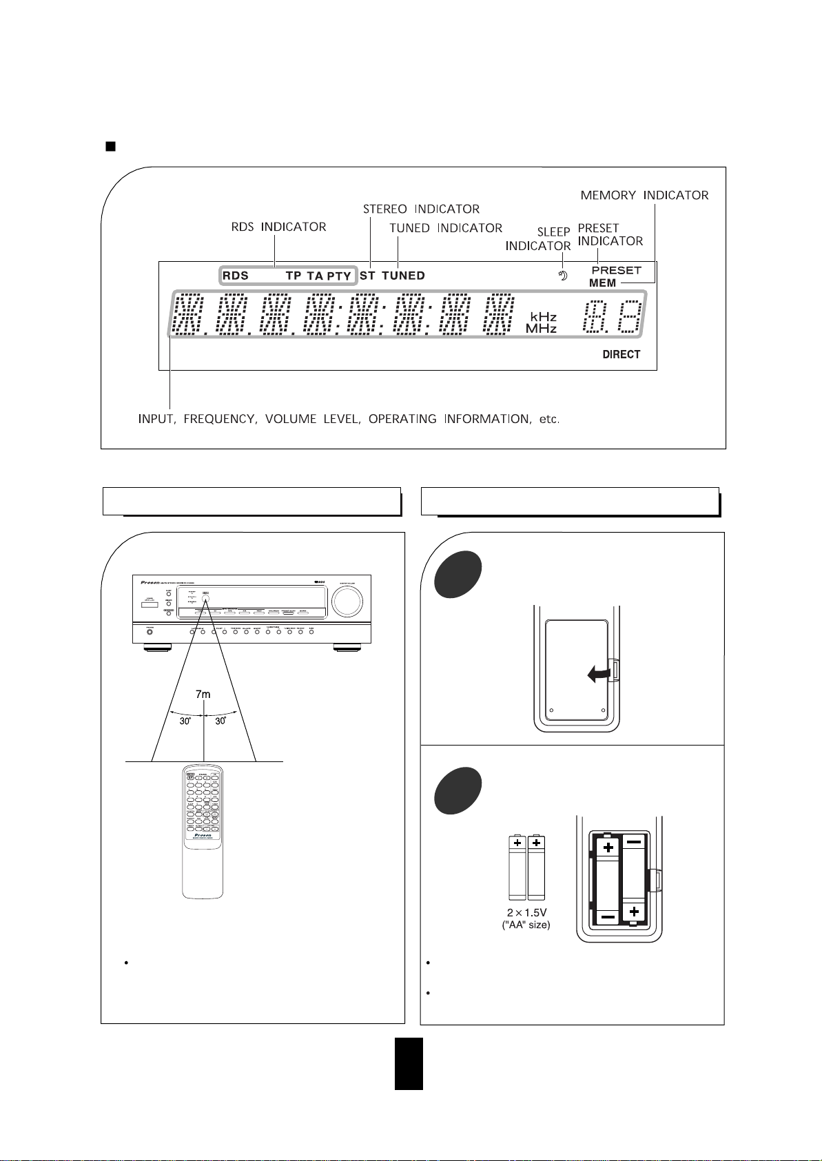
FLUORESCENT DISPLAY
For details, see the next page.
VOLUME CONTROL KNOB, UP/DOWN( )
BUTTONS
Adjust the volume to a comfortable listening level
with this knob or these buttons.
HEADPHONE JACK
Stereo headphones with a standard 1/4 inch plug
can be plugged into this jack for private listening.
SPEAKER A, B SELECTOR BUTTONS
These buttons allow you to select various combinations of speakers as follows:
To drive A speakers, press only the SPEAKER A
button (“SPK A” is displayed and the speaker A
indicator lights up).
To drive B speakers, press only the SPEAKER B
button (“SPK B” is displayed and the speaker B
indicator lights up).
To drive both A and B speakers, press the
SPEAKER A(or B) and B(or A) buttons in
order.(“SPK A B” is displayed and both of the
speaker A,B indicator lights up).
When using headphones for private listening,
press these buttons in order to switch off the
speaker A and B (“SPK OFF” is displayed).
ADJUST (-,+) BUTTONS
At the balance or tone mode, use these buttons to
change the setting.
INPUT SELECTOR BUTTONS
Press the button to select the desired input source.
TONE MODE BUTTON
When adjusting the tone (bass and treble), press
this button to select the desired tone mode.
Each time this button is pressed, the tone mode
is changed to bass or treble.
BALANCE BUTTON
When adjusting the sound volume balance, press
this button to enter the balance mode.
MEMORY BUTTON
Press this button to store preset stations.
TUNING/PRESET UP/DOWN( BUTTONS
Press these buttons to tune in the desired stations.
TONE DIRECT BUTTON
Press this button to listen to a program source without the tone effect.
TUNING MODE BUTTON
Press this button to select the tuning mode or the
preset mode.
PRESET SCAN BUTTON
Press this button to scan the stations in the preset
sequence.
FM MODE BUTTON
Press this button to select the desired FM mode.
Each time this button is pressed, the FM mode is
changed to the stereo mode or the mono mode.
MUTING BUTTON
Press this button to temporarily mute the sound.
Press again to resume the previous sound level.
BAND BUTTON
Press this button to select FM or AM.
NUMERIC BUTTONS(0 ~ 9)
Press these buttons to select or to store preset stations directly.
RDS BUTTON
Press this button to select RDS mode.
SEARCH MODE BUTTON
Press this button to select Search mode.
PTY SELECT BUTTON
Press this button to select Type of programs.
POWER SWITCH
Press this switch to turn the unit standby or off.
SLEEP BUTTON
Press this button to activate the sleep timer for a
specified period of time.
Each time this button is pressed, the sleep time
changes as follows:
DIMMER BUTTON
Press this button to select the brightness of the fluorescent display as desired.
Each time this button is pressed, the brightness
of the fluorescent display changes together as
follows:
Page 10
9
LOADING BA TTERIES
REMOTE CONTROLOPERA TION RANGE
1
Use the remote control unit within a range of
about 7 meters (23 feet) and angles of up to 30
degrees aiming at the remote sensor.
Remove the cover.
2
Remove the batteries when they are not used for a
long time.
Do not use the rechargeable batteries(Ni-Cd type).
Load two batteries matching the polarity.
FLUORESCENT DISPLAY
Page 11
10
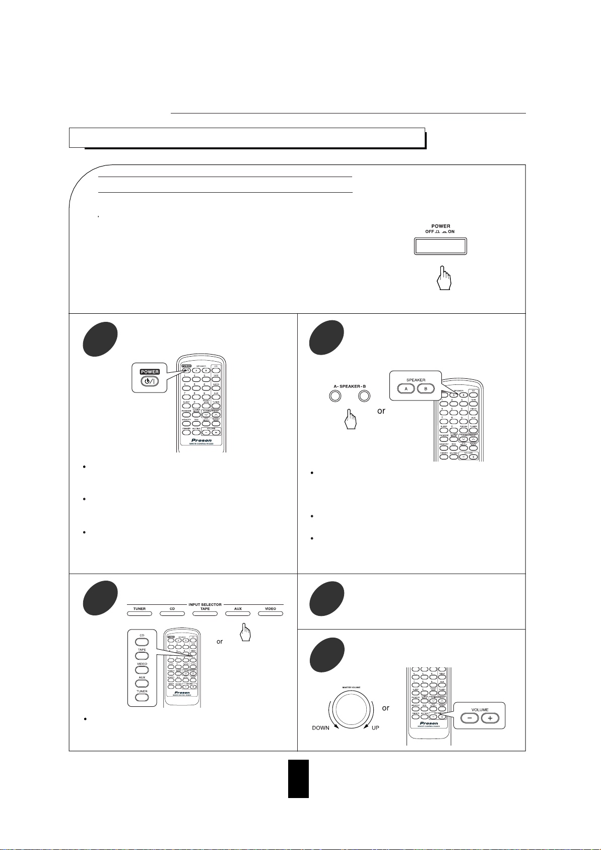
LISTENING TO APROGRAM SOURCE
Operations
Operate the selected component for
playback.
4
Adjust the volume to a comfortable listening level.
5
Then the corresponding speaker indication(“SPK A(or/and) B” is displayed and the
sound can be heard from the speakers connected to the selected speaker terminals.
when ON is selected, the "SPEAKER A (or/
and) B" indicator lights.
When using the headphones for private listening, press the corresponding SPEAKER button
to switch off both A and B speakers.
Turn the power on.
1
Switch the desired speakers on.
2
Each time the FM/AM button on the front panel or
the TUNER button on the remote control is
pressed, the band is changed to AM or FM.
Select the desired input source.
3
When the POWER button on the remote control is
pressed, this unit is turned on to enter the operating mode.
In the standby mode, if an INPUT SELECTOR button is pressed, the unit is turned on automatically
and the desired input is selected.
In the operating mode, when the POWER button
on the remote control is pressed, then it enters the
standby mode.
Before operation
• This unit enters the standby mode.
The lighting of STANDBY indicator means that the receiver is not
disconnected from the AC mains and a small amount of current is
retained to support the memorized contents and operation readiness.
•To switch the power off, push the POWER switch again. Then the
power is cut off and the STANDBY indicator goes off.
Push the POWER switch
Page 12
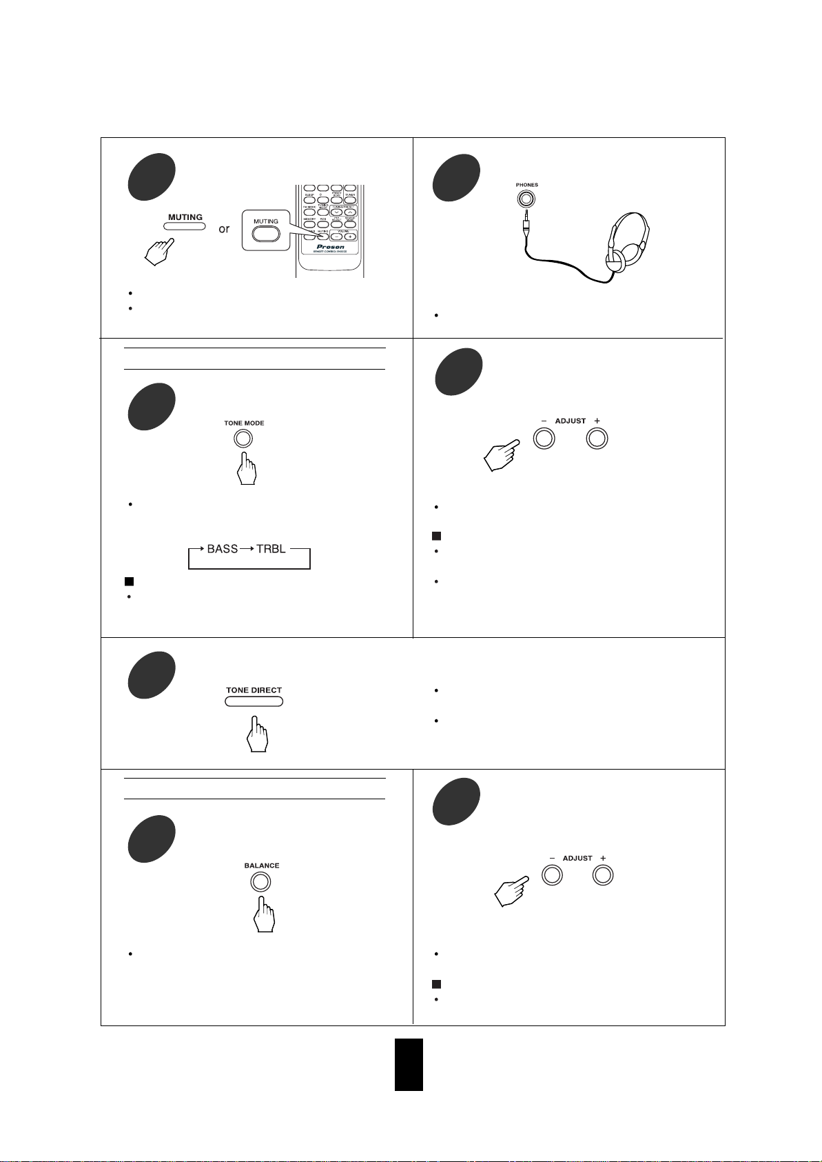
11
“TON DIR” is displayed and the sound that
bypasses the tone circuitry will be heard.
To cancel the tone direct function, press this
button again to display “TON CTRL”.
To listen to a program source without the tone effect.
10
Each time this button is pressed, the corresponding tone mode is selected and shown for
3 seconds as follows:
Enter the tone mode.
8
If the tone display disappears, start from the
step 8 again.
Notes:
Extreme settings at high volume may damage
your speakers.
In general, the bass and treble levels are
adjusted to 0.
At the desired tone mode, adjust the
tone as desired.
9
Adjusting the tone(bass and treble)
“BAL” and the balance level is displayed for 3
seconds.
Enter the balance mode.
11
If the balance display disappears, start from
the step 11 again.
Note:
In general, the balance level is set to 0.
Adjust the sound volume balance
between the left and right speakers.
12
Adjusting the sound volume balance
“MUTE” lights up and flickers.
To resume the previous sound level, press this
button again.
To mute the sound.
6
Be sure to switch off both A and B speakers.
To listen with the headphones.
7
Note:
When the tone direct function is activated, the
tone mode cannot be entered and “TON DIR”
flickers for 3 seconds.
Page 13
12
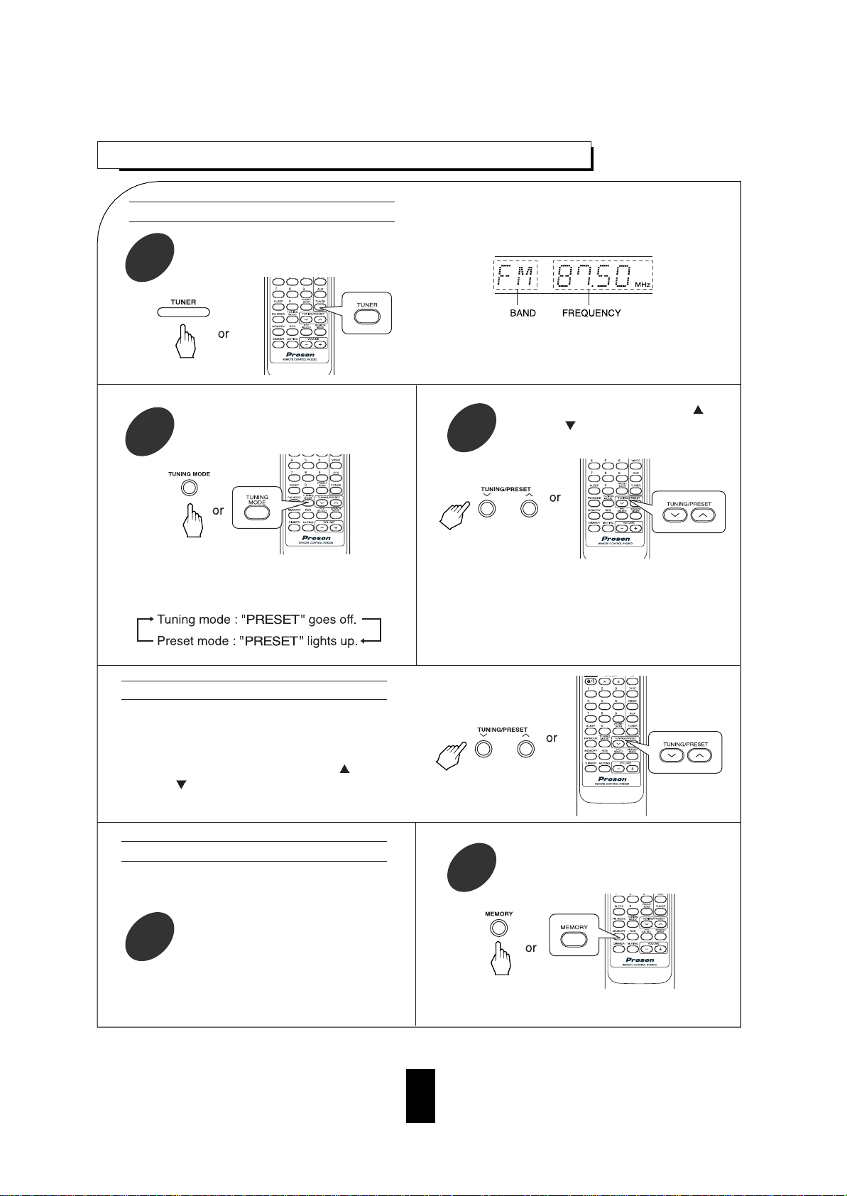
LISTENING TO RADIO BROADCASTS
Presetting radio stations
Auto tuning
• Each time this button is pressed, the mode
changes as follows:
• The tuner will now search until a station of sufficient strength has been found. The display
shows the tuned frequency and “TUNED”.
• If the station found is not the desired one, simply repeat this operation.
• Weak stations are skipped during auto tuning.
• Manual tuning is useful when you already know the
frequency of the desired station.
• Perform the steps 1 and 2 in “Auto tuning” procedure
and press the TUNING/PRESET UP(
) or
DOWN(
) button repeatedly until the right frequency
has been reached.
• You can store up to 30 preferred stations in the
memory.
• “MEM” is flickering for 5 seconds.
Manual tuning
• Each time this button is pressed, the band is
changed to FM or AM.
Select the tuner and then the desired band.
1
Select the tuning mode.
2
Press the TUNING/PRESET UP( )
or DOWN(
) button for more than
0.5 second.
3
Tune in the desired station with auto or
manual tuning.
1
Press the MEMORY button.
2
Page 14
13
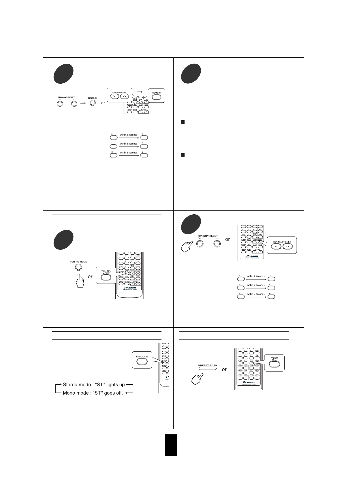
Repeat the above steps 1 to 3 to memorize other stations.
4
After selecting the tuner as an input
source, select the preset mode.
1
Listening to FM stereo broadcasts
• Then “PRESET” lights up.
MEMORY BACKUP FUNCTION
The following items, set before the receiver is
turned off, are memorized.
• INPUT SELECTOR settings
• Preset stations,etc.
Note
• If the electricity fails or the AC input cord is dis-
connected for more than several days, they are
all cleared. So you should memorize them
again.
• While listening to FM broadcasts,
• Each time this button is pressed,
the FM mode changes as follows:
Scanning preset stations in sequence
• The receiver will start scanning the stations in the
preset sequence.
• At the desired station, press this button again to
stop scanning.
• When using the NUMERIC buttons on the remote
control.
Examples) For “3” :
For “15” :
For “30” :
• To select numbers less than 10, press "0" and then
the number. As an example, to select number 5,
press "0" and "5". (Optionally, you may press just
the number "5" and then wait a few seconds.)
Tuning to preset stations
Select the desired preset number.
2
Select the desired preset number
(1~30) and press the MEMORY button.
3
• When using the NUMERIC buttons on the remote
control.
Examples) For “3” :
For “15” :
For “30” :
• The station has now been stored in the memory.
• When using the NUMERIC buttons, the station is
stored automatically without pressing the MEMORY
button.
• A stored frequency is erased from the memory by
storing another frequency in its place.
• If “MEM” goes off, start again from the above step 2.
• When FM stereo broadcasts are poor because of
weak broadcast signals, select the FM mono
mode to reduce the noise, then FM broadcasts
are reproduced in monaural sound.
Page 15
14
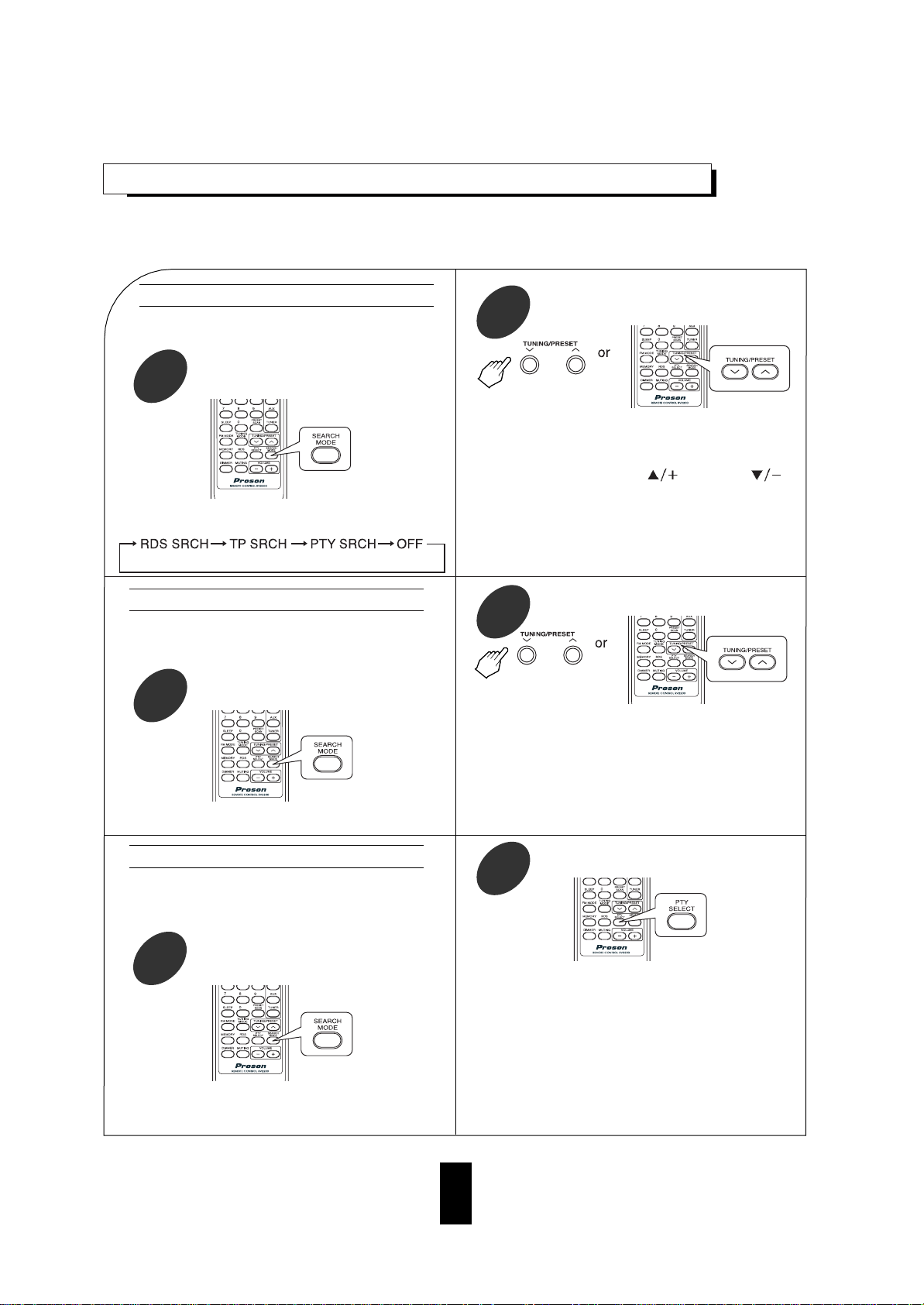
LISTENING TO RDS BROADCASTS(FM ONL Y)
While displaying “TP SRCH”.
2
While displaying “PTY SRCH”, select the
desired program type.
2
While displaying “RDS SRCH”
2
• Use this function to automatically search and
receive the stations offering RDS services.
RDS(Radio Data System) is a method for sending information signals together with the transmitter signals. Your tuner is capable of translating these signals and putting the information on the display. These codes contain the following informations.
Program Service name(PS), A list of Program Types(PTY), Traffic Announcement(TA), Clock Time(CT), Radio Text(RT).
• Use this function to automatically search and
receive the stations broadcasting the desired
program type.
• “PTY SRCH” is displayed.
• Each time this button is pressed, one of 32 different types of programs is selected.
(NEWS, AFFAIRS, INFO, SPORT, EDUCATE, DRAMA, CULTURE, SCIENCE, VARIED, POP M, ROCK M, EASY M, LIGHT
M, CLASSICS, OTHER M, WEATHER, FINANCE, CHILDREN,
SOCIAL, RELIGION, PHONE IN, TRAVEL, LEISURE, JAZZ,
COUNTRY, NATION M, OLDIES, FOLK M, DOCUMENT, TEST,
ALARM, NONE)
• When “PTY SRCH” is not displayed, repeat again
from the above step 1.
• Each time this button is pressed, the search
mode changes as follows;
In the FM mode, select the RDS search
mode.
1
RDS search
PTY search
In the FM mode, select the TP search
mode.
1
• Use this function to automatically search and
receive the stations broadcasting the traffic
program.
• “TP SRCH” is displayed.
TP search
• The tuner automatically searches stations offering
RDS services and the station name is displayed.
• If the station found is not the desired one, press
the TUNING/PRESET UP(
) or DOWN( )
button again while the RDS indicator is flickering.
• If no other RDS station is found, “NO RDS” is displayed.
• When “RDS SRCH” is not displayed, repeat again
from the above step 1.
• The tuner automatically searches for stations
broadcasting the traffic program.
• “NO TP”is displayed if the signal is too weak or
there are no stations broadcasting the traffic program.
• When “TP SRCH” is not displayed, repeat again
from the above step 1.
In the FM mode, select the PTY search
mode.
1
Page 16
15
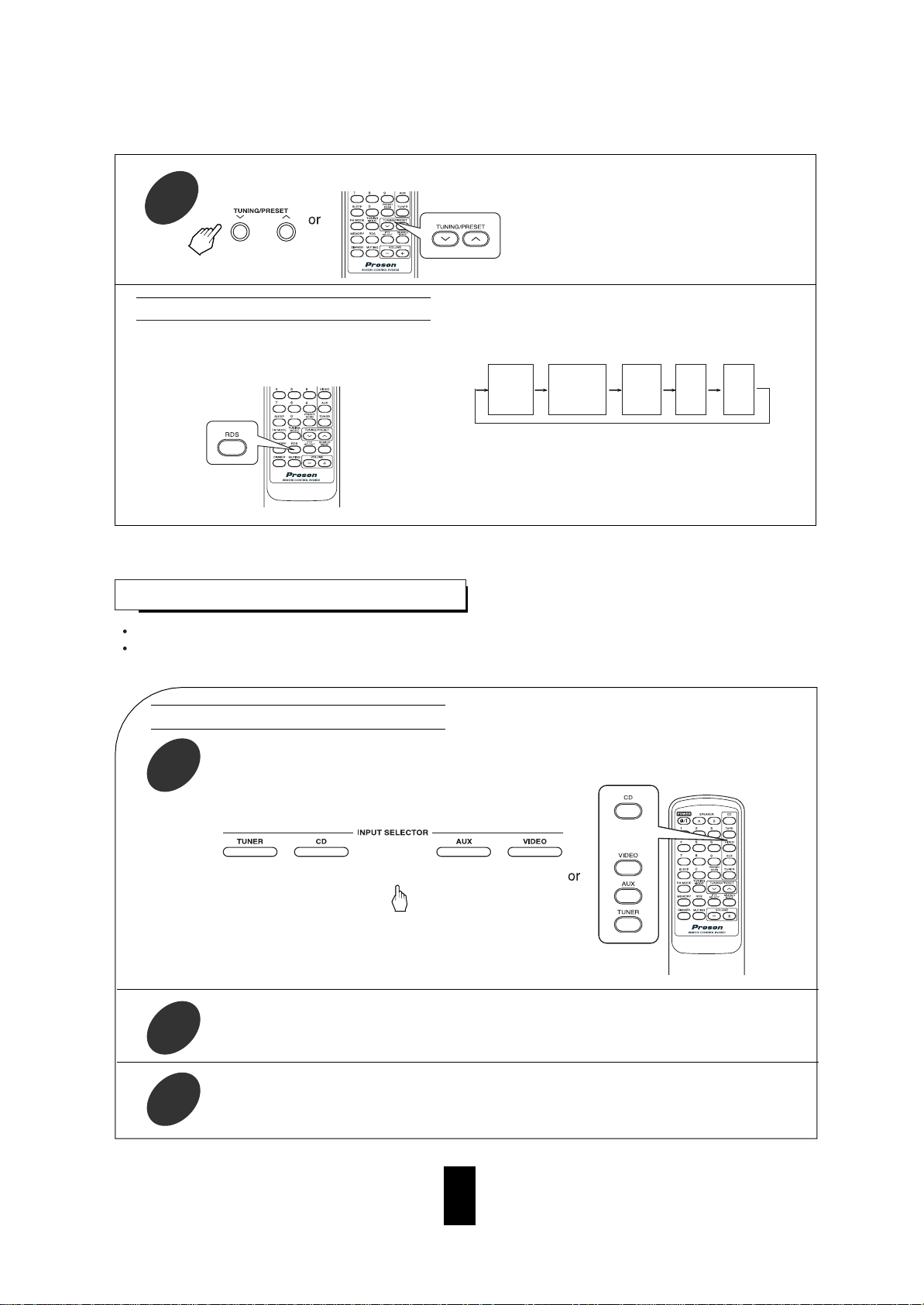
• Each time this button is pressed, the display mode
changes as follows;
• If the signals are too weak or no RDS service is
available, “NO NAME”, “NO PTY”, “NO TIME” or
“NO TEXT” will be displayed.
In the FM mode.
RDS
Frequency
Program
Service name
(PS)
Program
Type
(PTY)
Clock
Time
(CT)
Radio
Text
(RT)
3
• The tuner automatically searches a station
offering PTY services.
• If no station is found, “NO PTY” is displayed.
RECORDING
The volume, tone(bass, treble) and balance settings have no effect on the recording signals.
When you select tuner, CD or AUX as a recording source, recording may be made on TAPE or VIDEO, or
both simultaneously.
Start recording on the TAPE.
2
Recording with TAPE
Start play on the desired input.
3
Select the desired input as a recording source except for TAPE.
1
Page 17
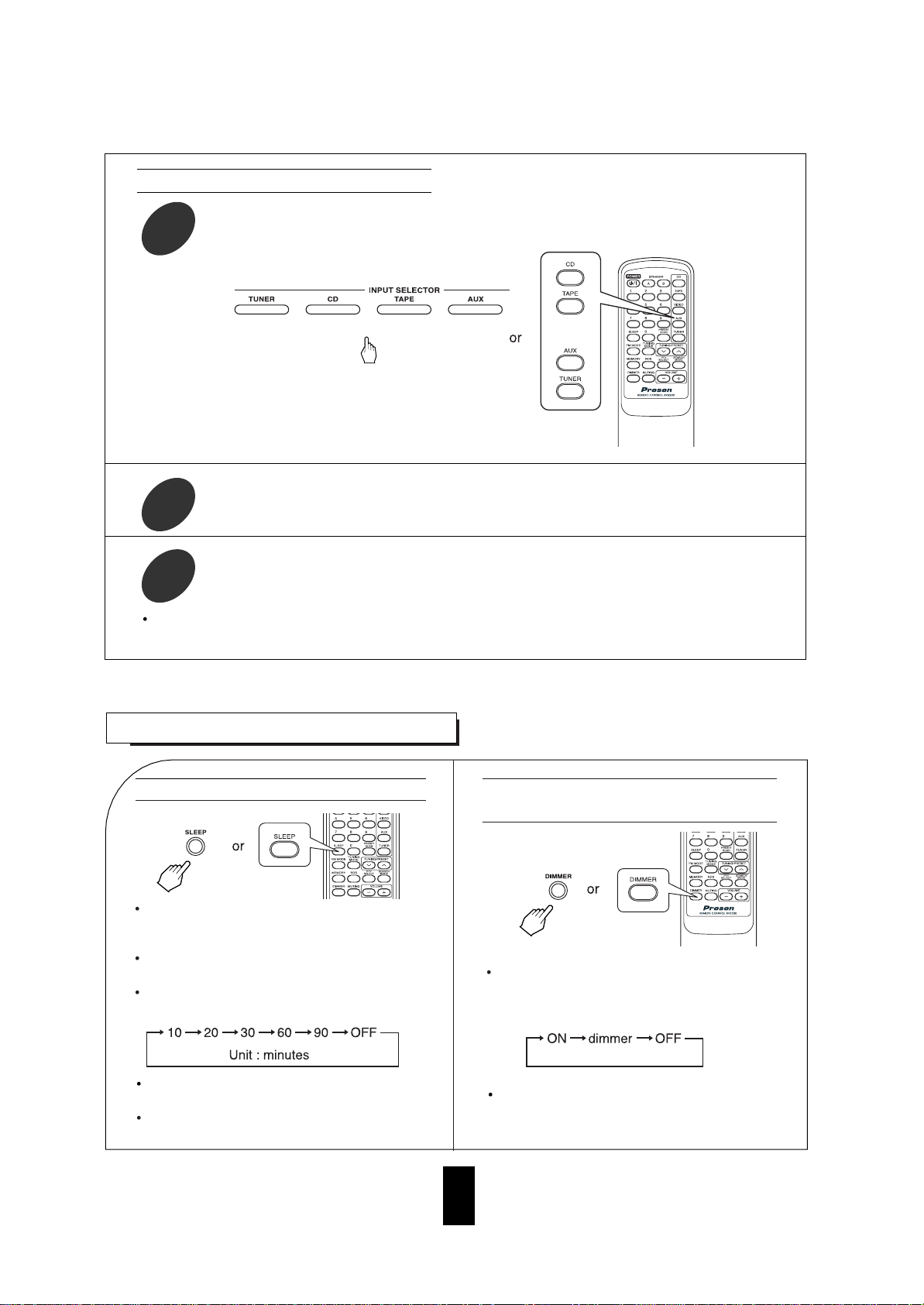
Operating the sleep timer
The sleep timer allows the system to continue to
operate for a specified period of time before
automatically shutting off.
To set the receiver to automatically turn off
after the specified period of time.
Each time this button is pressed, the sleep
time changes as follows:
Each time this button is pressed, the brightness of the fluorescent display changes
together as follows:
Adjusting the brightness of the fluorescent display
OTHER FUNCTIONS
16
Start recording on the VIDEO.
2
Recording with VIDEO
Start play on the desired input.
3
The audio signals from the desired input will be recorded onto the VIDEO.
Select the desired input as a recording source except for VIDEO.
1
While operating the sleep timer, SLEEP indicator
lights up.
When the sleep time is selected, the fluorescent
display is dimly lit.
In the display OFF mode, pressing any button
will restore the display ON mode.
Page 18
17
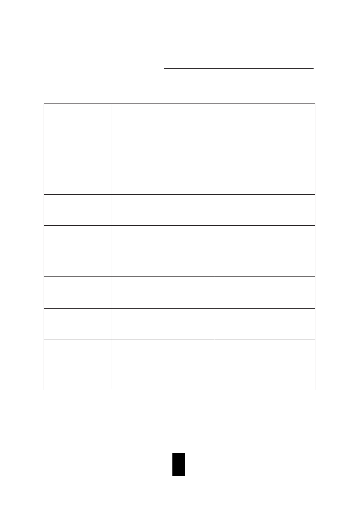
Troubleshooting Guide
PROBLEM POSSIBLE CAUSE REMEDY
If a fault occurs, run through the table below before taking your receiver for repair.
If the fault persists, attempt to solve it by switching the receiver off and on again. If this fails to resolve the situation,
consult with your dealer. Under no circumstances should you repair the receiver yourself as this could invalidate
the warranty.
No power
No sound
Stations cannot be
received
Preset stations cannot be
received
Poor FM reception
Continuous hissing noise
during FM reception, especially when a stereo broadcast is received.
Continuous or intermittent
hissing noise during AM
reception, especially at
night.
No recording
Remote control unit does
not operate.
• The AC input cord is disconnected.
• Poor connection at AC wall outlet or the
outlet is inactive.
• The speaker cords are disconnected.
• The volume is adjusted too low.
• The MUTING button on the remote control
is pressed to ON.
• Speakers are not switched on.
• Incorrect selection of the input source.
• Incorrect connections between the components.
• No antenna is connected.
• The desired station frequency is not tuned
in.
• The antenna is in wrong position.
• An incorrect station frequency has been
memorized.
• The memorized stations are cleared.
• No antenna is connected.
• The antenna is not positioned for the best
reception.
• Weak signals.
• Noise is caused by motors, fluorescent
lamps or lightning, etc.
• Incorrect selection between the components.
• Incorrect operation of each component for
playback and recording.
• Batteries are not loaded or exhausted.
• The remote sensor is obstructed.
• Connect the cord securely.
• Check the outlet using a lamp or another
appliance.
• Check the speaker connections.
• Adjust the volume.
• Press the MUTING button to cancel the
muting effect.
• Press the SPEAKER A or B button to ON.
• Select the desired input source correctly.
• Make connections correctly.
• Connect an antenna.
• Tune in the desired station frequency.
• Move the antenna and retry tuning.
• Memorize the correct station frequency.
• Memorize the stations again.
• Connect an antenna.
• Change the position of the antenna.
•
Change the position of the antenna.
•
Install an outdoor antenna.
• Keep the receiver away from noise
sources.
• Install an outdoor AM antenna.
• Make connections correctly.
• Operate each component correctly.
• Replace the batteries.
• Remove the obstacle.
Page 19
18
AMPLIFIER SECTION
Power output, stereo mode, 8 Ω, THD 0.2 %, 20 Hz~20 kHz ................................................................ 2X100 W
Total harmonic distortion, 8 Ω, 100 W, 20 Hz~20 kHz ............................................................................. 0.04 %
Intermodulation distortion
60 Hz : 7 kHz= 4 : 1 SMPTE, 8 Ω, 100 W ................................................................................................... 0.1 %
Input sensitivity, 47 kΩ
Line .......................................................................................................................................................... 200 mV
Signal to noise ratio, IHF “A” weighted
Line ............................................................................................................................................................. 95 dB
Frequency response
Line, 10 Hz~100 kHz ................................................................................................................................
3 dB
Output level
TAPE/VCR OUT, 2.2 kΩ .......................................................................................................................... 200 mV
Bass/Treble control, 100 Hz/10 kHz ........................................................................................................ 10 dB
FM TUNER SECTION
Tuning frequency range ................................................................................................................ 87.5~108 MHz
Usable sensitivity, THD 3%, S/N 30 dB ..................................................................................................... 15 dBf
50 dB quieting sensitivity, mono/stereo .......................................................................................... 25.2/45.2 dBf
Signal to noise ratio, 65 dBf, mono/stereo ............................................................................................. 68/65 dB
Total harmonic distortion, 65 dBf, 1 kHz, mono/stereo .......................................................................... 0.5/0.8%
Frequency response, 25 Hz~14 kHz ......................................................................................................... 3 dB
Stereo separation, 1 kHz ............................................................................................................................ 35 dB
Capture ratio ................................................................................................................................................ 4 dB
IF rejection ratio .......................................................................................................................................... 80 dB
AM TUNER SECTION
Tuning frequency range ................................................................................................................ 522~1611 kHz
Usable sensitivity .................................................................................................................................... 800 V/m
Signal to noise ratio .................................................................................................................................... 40 dB
Selectivity ................................................................................................................................................... 25 dB
GENERAL
Power supply .................................................................................................................................. 230V~ 50 Hz
Power consumption ................................................................................................................................... 200W
Dimensions (W H D) ......................................................... 440 138 332 mm(17-3/8 5-7/16 13 inches)
Weight (Net) ............................................................................................................................. 9.0 kg(19.85 lbs)
Note: Design and specifications are subject to change without notice for improvements.
Specifications
 Loading...