

Page 1
STEREO RECEIVER AMPLIFIER
User's Manual
R
RV2040
PHONE
A/B/C/D
SCAN+FM/AM
SCAN-
NO.1-8
MEMORY
POWER
VOLUME - VOLUME+
AUTO
INPUT
STEREO RECEIVER AMPLIFIER RV2040
Page 2
Voltage
Votages are 230V AC,50Hz.
Page 3
Set up and Maintenance of the Receiver
Getting Started
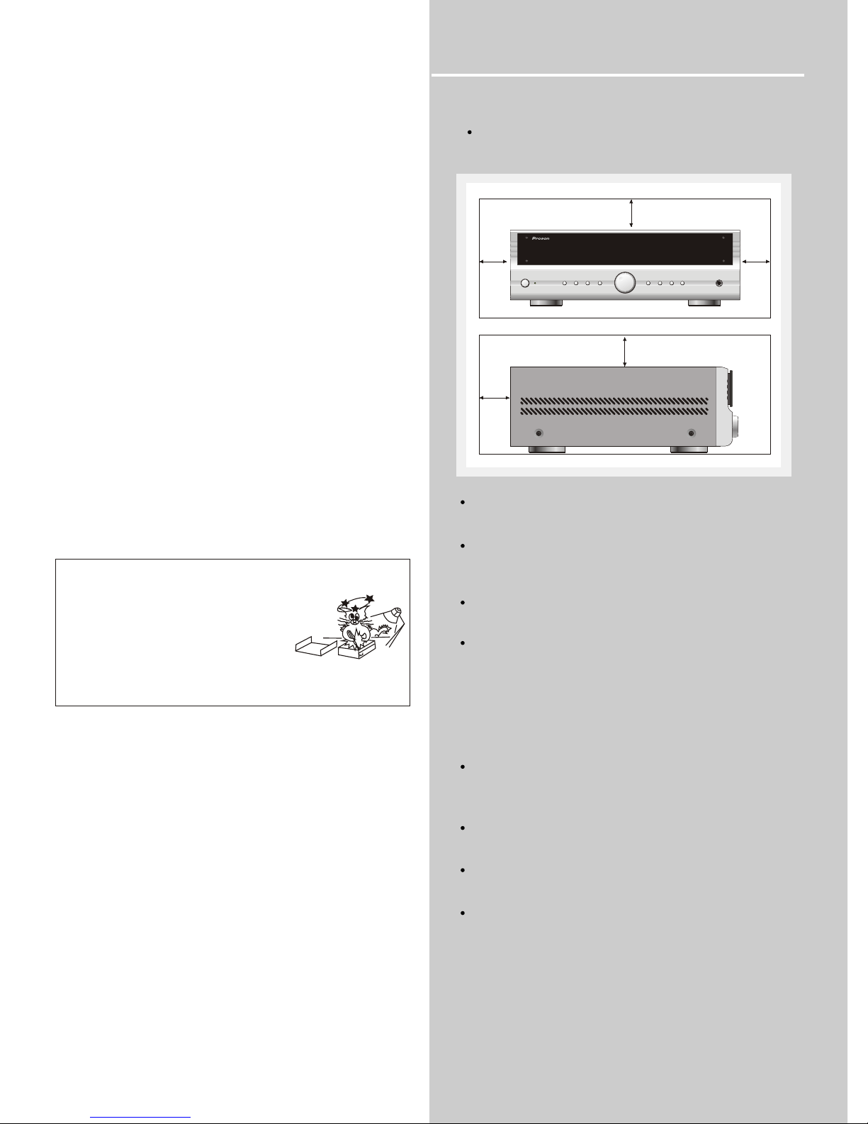
15cm/6"
10cm/
4"
10cm/
4"
Provide spaces for sufficient ventilation as
indicated:
Do not connect to the AC power cords until all
are completed.apparatus
Do not use your receiver immediately after
transferring it from a cold place to a warm place:
there is risk of condensation.
Do not expose your receiver to water and
excessively high temperatures.
After having disconnected your receiver, clean
the case with a soft cloth, or with a slightly damp
leather chamois. Never use strong solvents.
Protect your receiver from Overheating
Do not block ventilation holes in any .
Arrange receiver so that air can circulate
freely.
apparatus
the
Do not stack receiver directly on top of each
other.
the
Allow adequate ventilation when placing your
receiver a stand.
Place an amplifier near the top shelf of the stand
so heated air rising from it will not affect other
. If you have a satellite receiver, you
should place it on the top shelf.
apparatus
10cm/
4"
15cm / 6"
15. Cleaning - Unplug this unit from the wall outlet
before cleaning. Do not use liquid cleaners or
aerosol cleaners. Use a damp cloth for cleaning.
16. Power lines - An outdoor antenna should be
located away from power lines.
17. Object and Liquid Entry - Care should be taken
so that objects do not fall and liquids are not spilled
into the enclosure through openings.
13.Unplug this apparatus during lighting storms or
when unused for long periods of time.
14.Refer all servicing to qualified service personnel.
Servicing is required when the apparatus has been
damaged in any way. Such as power-supply cord or
plug is damaged, liquid has been spilled or objects
have fallen into the apparatus. The apparatus has
been exposed to rain or moisture. Does not operate
normally or has bee dropped.
These servicing instructions are of
use by qualified service personnel
only. To reduce the risk of electric
shock do not perform any servicing
other than that contained in the
operating instructions unless you
are qualified to do so.
PHONE
A/B/C/D
SCAN+FM/AM
SCAN-
NO.1-8
MEMORY
POWER
VOLUME - VOLUME+
AUTO
INPUT
STEREO RECEIVER AMPLIFIER RV2040
Page 4

TABLES OF CONTENTS
1
UNPACK THE RECEIVER.....................................................................................................
ABOUT REMOTE CONTROL................................................................................................
BASIC CONNECTIONS.........................................................................................................
CONNECTING THE SPEAKERS..........................................................................................
CONNECTING FOR POWER................................................................................................
USING HEADPHONES...........................................................................................................
FIRST THING FIRST..................................................................................................
RECEIVER CONTROLS & OPERATIONS....................................................
GENERAL CONTROLS...........................................................................................................
DISPLAY MESSAGES.............................................................................................................
TUNING THE RECEIVER........................................................................................................
CONNECTING AUXILIARY COMPONENTS............... .............................
BEFORE YOU CONNECT......................................................................................................
.......................................................................CONNECTING A COMPACT DISC PLAYER
RECEIVER/TUNER OPERATION.........................................................................................................................
REMOTE CONTROL OPERATION.......................................................................................................................
GENERAL..............................................................................................................................................................
CLEANING THE EXTERIOR.................................................................................................................................
EQUIPMENT SPECIFICATIONS........................................................................
2
2
3
4
5
6
6
7
8
8
8
8
8
9
9
9
9
7
SELECT THE AM/FM BAND.........................................................................................................
TUNING.......................................................................................................................
AUTO TUNING...........................................................................................................................
STORING STATIONS IN MEMORY...............................................................................................
MANUAL
TO STORE STATION...................................................................................................................
MANUAL PRESET.......................................................................................................................
RETRIEVING PRESET STATIONS...............................................................................................
11
12
CARE AND MAINTENANCE.................................................................................
TROUBLESHOOTING TIPS..................................................................................................
11
13
13
13
13
13
13
14
REMOTE CONTROL................................................................................................................
10
Page 5
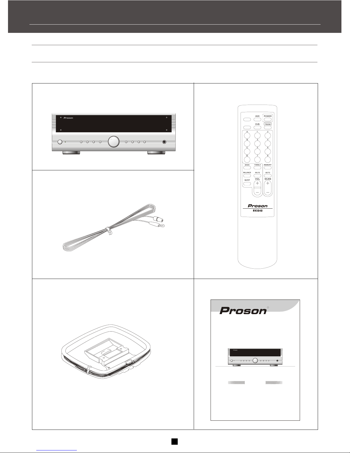
One instruction book
Indoor FM antenna
AM loop antenna
One receiver unit
2
One Remote Control
FIRST THINGS FIRST
UNPACKING THE RECEIVER
You should receiver the following items:
PHONE
A/B/C/D
SCAN+FM/AM
SCAN-
NO.1-8
MEMORY
POWER
VOLUME - VOLUME+
AUTO
INPUT
STEREO RECEIVER AMPLIFIER RV2040
STEREO RECEIVER AMPLIFIER
User's Manual
PHONE
A/B/C/D
SCAN+FM/AM
SCAN-
NO.1-8
MEMORY
POWER
VOLUME - VOLUME+
AUTO
INPUT
STEREO RECEIVER AMPLIFIER RV2040
R
RV2040
VCR
CD
Page 6
PHONE
A/B/C/D
SCAN+FM/AM
SCAN-
NO.1-8
MEMORY
POWER
VOLUME - VOLUME+
AUTO
INPUT
STEREO RECEIVER AMPLIFIER RV2040
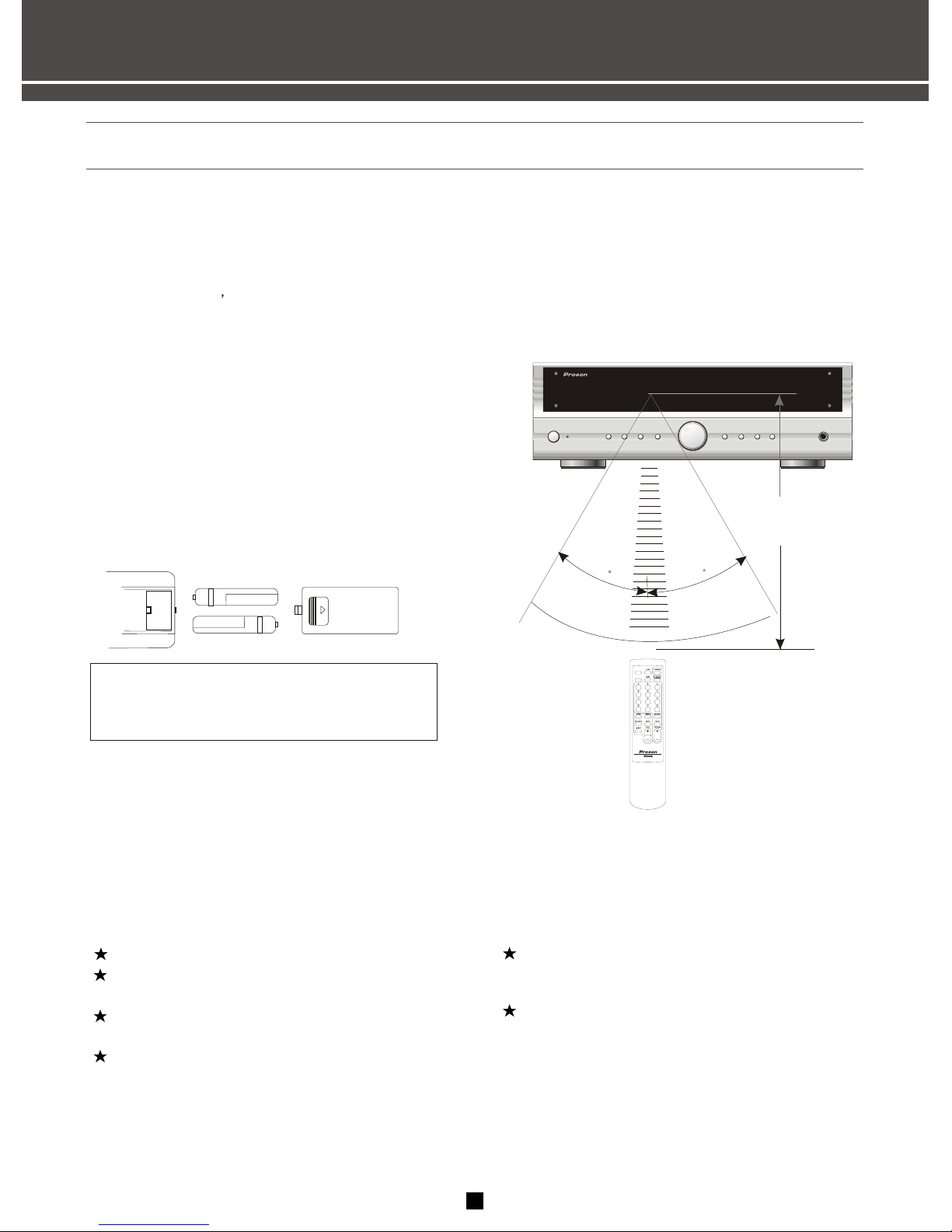
Installing batteries in the remote
controller
Since the remote controller will be used for
many of this unit s control operations, you
should begin by installing the supplied batteries.
1.Turn the remote controller over and slide
the battery compartment cover in the direct ion of the arrow.
2. Insert the batteries(AAA,R03,UM-4 TYPE)
according to the polarity markings on the
inside of the battery compartment.
3.Close the battery compartment cover.
Notes about the remote controller
Batteries replacement
If you find that the remote controller must be used
close to the main unit, the batteries are weak.
Replace both batteries with new ones.
Notes
Use AAA,R03,UM-4 batteries.
Be sure the polarities are correct.(See the illu stration inside the battery compartment.)
Remove the batteries if the remote controller
is not used for an extended period of time.
If batteries leak, dispose of them immediately.
Avoid touching the leaked material and contact
with clothing, etc. Clean the battery compartm ent thoroughly before installing new batteries.
Remote controller operation range
Within approximately
6m(19.7feet)
30
30
Notes
The area between the remote controller and
the main unit must be clear of large obstacles.
Do not expose the remote control sensor to
strong lighting, in particular an inverter type
fluorescent lamp. Otherwise, the remote
controller may not work properly.If necessary,
position the main unit away from direct lighting.
FIRST THINGS FIRST
ABOUT REMOTE CONTROL
3
Danger of explosion if battery is
incorrectly replaced.
CAUTION
VCR
CD
Page 7
FIRST THINGS FIRST
BASIC CONNECTIONS
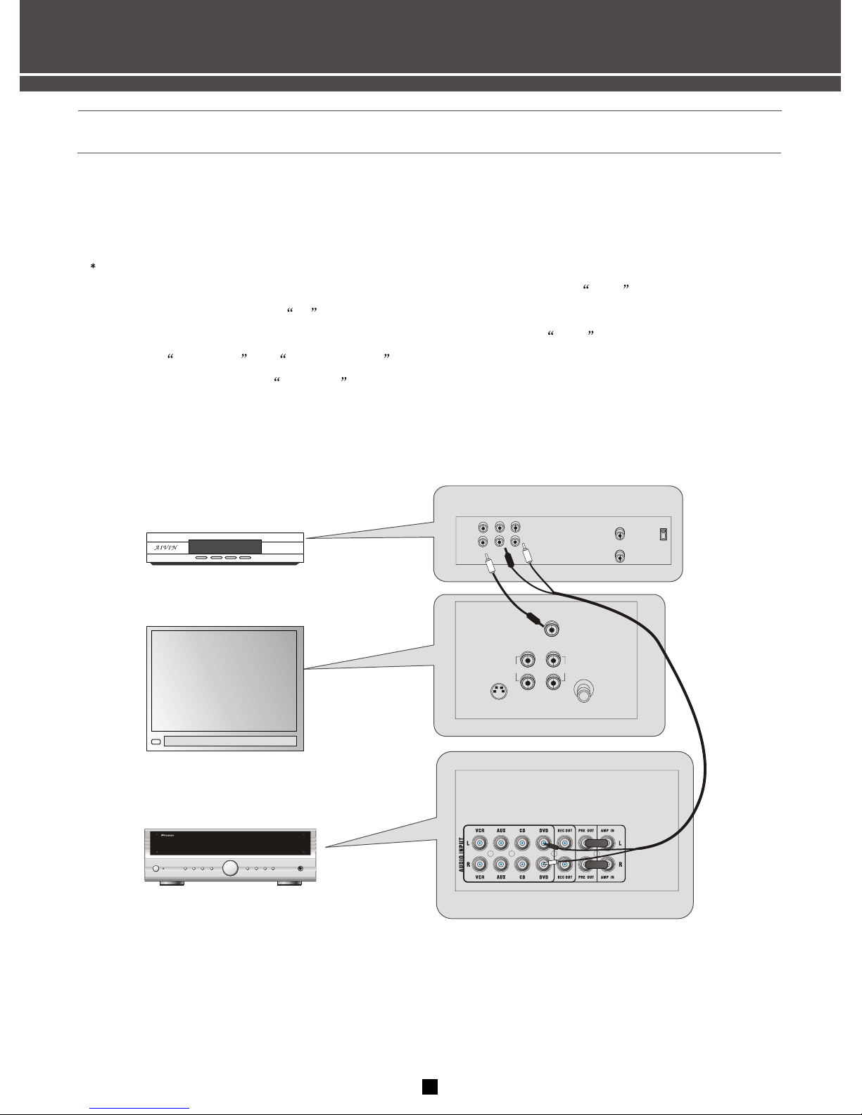
Assuming you have a DVD, the following steps will help you quickly set up your new receiver. If you have
more electronic components, consult the table of contents or index for the page on which to find the
connection description that best suits your situation.
the wires(bought from store ) and jacks have been color-coded to assist you.
1.Using an audio wire with red and white connectors, connect the audio OUT jack on the back of
your stereo DVD to the audio IN jack under the DVD heading on the back of the receiver.
2.Using the video cable with yellow connectors, connect the video OUT jack on the back of your
DVD to the VIDEO IN or VIDEO INPUT on the back of your TV. If there are multiple video jacks
on the back of your TV, use VIDEO 1 .
L/
MONO
OUT AUDIO
RIGHT
IN
CABLE/
ANTENNA
VIDEO
INPUT
S-VIDEO
DVD
VIDEO
OUT
IN
R L
IN FROM ANT
OUT TO TV
Ch3
Ch4
AUDIO
RECEIVER
TV
4
PHONE
A/B/C/D
SCAN+FM/AM
SCAN-
NO.1-8
MEMORY
POWER
VOLUME - VOLUME+
AUTO
INPUT
STEREO RECEIVER AMPLIFIER RV2040
199
Page 8
FIRST THINGS FIRST
CONNECTING THE SPEAKERS
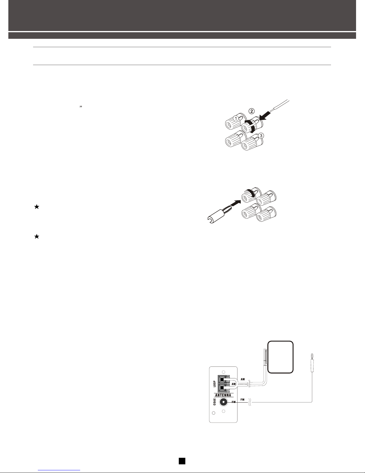
CONNECTING THE WIRES
CONNECTING THE MAIN SPEAKERS
The two main speakers should be set between six and 10 feet apart. Putting the speakers any closer or
any farther apart may result in distorted sound.
The speakers should also form a 45 degree angle to the central listening point in the room, creating a
triangle of listening enjoyment.
CONNECTING THE ANTENNAS
The AM and FM antennas connect to the AM and FM
terminals on the system's back panel. They must
be hooked up for you to receive clear reception.
Uncoil the antenna wires and locate the bare ends.
Press down on the tab to open the terminal and
insert the wire. Snap the tab closed.
After connecting the antennas, extend them to
their full length and adjust their positioning for
better reception.
Method 1
Method 2
1.Loosen the knob.2.Insert the bare wire.[Remove
approx.5mm(1/4 ) insulation from the speaker
wires]. 3.Tighten the knob and secure the wire.
Or you also may use banana plug.
Speaker Polarity
When connecting the speakers, make sure the
polarities("+" speaker wire to "+" on the receiver)
of speaker wires and terminals are matched.
If the cords are reversed, the sound will be distort-
ed and will lack bass("out of phase"effect).
NOTE:
Do not let the bare speaker wires touch each
other or any metal part of this unit. This could
damage this unit or the speakers, or both.
Connect the speakers terminals to your speak-
ers with the wire of the proper gauge
(keep as short as possible).if the connections are
faulty,no sound will be heard from the speakers.
5
Page 9
FIRST THINGS FIRST
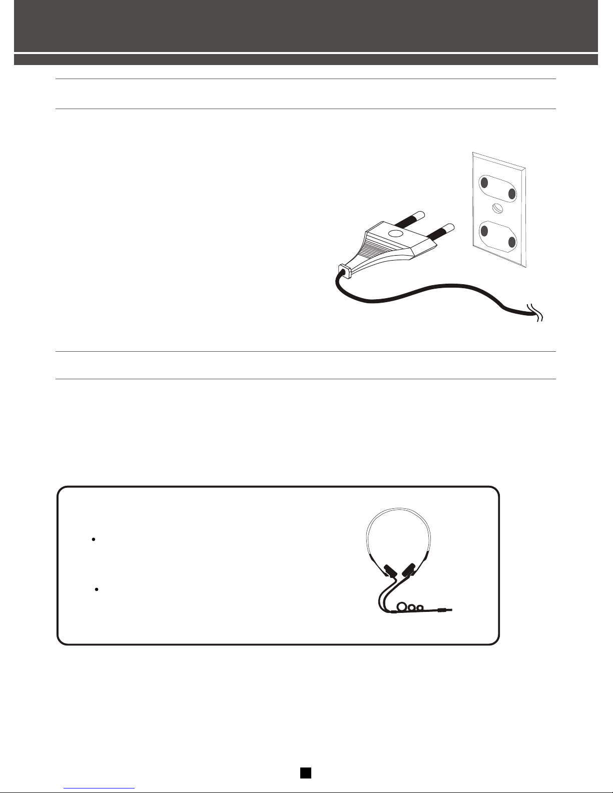
CONNECTING FOR POWER
Make sure you connect all your other electronic
components and the speakers before plugging
your receiver into the outlet.
Plug the power cord in the wall outlet, matching
the wide blade of the plug with the wide slot in
the outlet. Be sure to insert the plug completely.
USING HEADPHONES
To listen privately through your audio system, use the PHONES jack on the receiver. How ever, make sure
you turn down the volume before you put on the headphones.Increase the volume to the desired level after
headphones are in place.
Hearing Comfort & Well-Being
Do not play your headset at a high volume.
hearing experts advise against continuous
extended play.
If you experience a ringing in your ears,
reduce volume or discontinue use.
6
Page 10
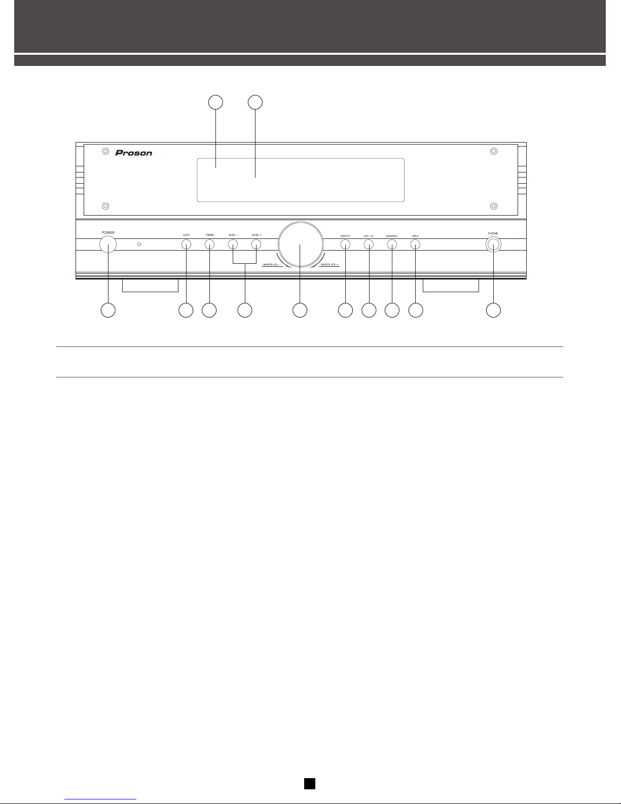
RECEIVER CONTROLS & OPERATIONS
GENERAL CONTROLS
1.Remote control sensor
Receives signals from the remote controller.
2.Display panel
Display a variety of information. e.g. source etc.
3.POWER switch
Press this switch to turn on the power. Press the
switch again to turn off the power.
4.TUNER automatically tuning button
Press and hold the button 3 seconds, All stations
are stored automatically.(AM/FM is detached)
5.FM/AM band switches button
Press the button to select input source tuner and
switch the reception band between FM and AM.
6.TUNING SCAN+,SCAN- buttons
Press the SCAN+ side to tune in to a higher
Frequency. Press the SCAN- side to tune in to a
lower frequency.
7.MASTER VOLUME
Rotate the knob to adjust volume. Volume
increase when clockwise direction rotate the
knob, volume reduction when anti-clockwise
direction rotate the knob.
8.A/B/C/D button
Press the button to select a group of preset
stations on the tuning status.
9.Number 1-8 button
Press the button to call preset station number
on the tuning status.
10.MEMORY button
Use the button to enter a station to memory.
11.Input selector knob
Press the button to select the input source you
want to listen to.
12.PHONE jack
Allows you enjoy for private listening with
headphones. When you connect headphones,
no signals are output to all speakers.
7
6
5
4
3
8
11
7
129
10
1 2
STEREO RECEIVER AMPLIFIER RV2040
Page 11
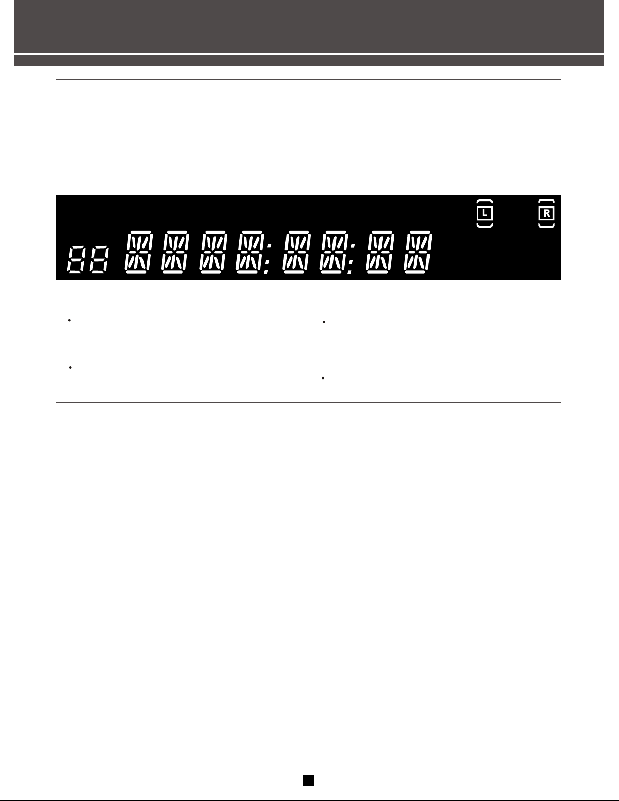
RECEIVER CONTROLS & OPERATIONS
STEREO
Tuner stereo signal detected.
TUNED
Tuner station detected.
SLEEP
Unit in Sleep mode
KHz
MH
Tuner frequency unit
MH
KH
MEMORY
SLEEP
TUNEDSTEREO
L
R
DISPLAY MESSAGES
The following is an example of all the display messages you may encounter while using your receiver.
Specific messages are referenced within the section(s) they apply.
TUNING THE RECEIVER
1.Push the FM /AM button on the front panel (or
the AM/FM button on the remote) to activate the
tuner.
2.When using the remote you must press the AM/
FM button on the remote again to select the FM
or AM band.
TUNING
Press the SCAN+ button on your remote button
to move up the AM or FM band.
Press the SCAN- arrow button on your remote to
move down the AM or FM band.
you may press and hold SCAN+ or SCAN- buttons
3 seconds to find next station.
MANUAL
automatically
AUTO TUNING
Use the AUTO feature to automatically search for
stations of sufficient strength.
Press and hold AUTO button for 3 seconds on the
remote. Radio frequencies will be browsed and
radio station stored automatically. When all
available radio stations are stored or if all 32
memory locations are full,the auto preset will stop.
NOTE:
1. If there is interference, modify the location of
the antenna until the optimal sound is heard. TV
and other electronic devices could be the cause
of interferences so try to position the antenna
away of them.
2. Weak signal can affect the "auto Search
function". Adjust the antenna for better recep tion for more efficient search.
SELECT THE AM/FM BAND
8
z
z
z
Page 12
RECEIVER CONTROLS & OPERATIONS
TO STORE A STATION
1.Press the FM/AM button on the front panel (or
the AM/FM button on the remote).
2.Select the station you want to store in memory
using the methods described above.
3.Press the MEMORY button on the remote
"MEMORY" blinks in the display. While "MEMORY"
is blinking, press number buttons on the remote
for the station.
If the Memory indicator on the display
turns off before you preset your station
selection, press MEMORY again.
1. Press FM/AM button on the front panel or the
remote control to select tuner mode.
on the front panel or the
remote control to s
desired
the numeric keys on the remote
control to s
desired
2.Press A/B/C/D button
elect the group of preset
station that you are .
3.Press button
elect the number of preset station
that you are . Station selected is
displayed on the front panel display.
4.In the same way, You can select other stations
stored.
RETRIEVING PRESET STATIONS
1. Select the band wave by pressing FM/AM
repeatedly.
2. Tune to a radio station(see "Manual tuning" on
page 8 above for details).
3.Select a group (A- D) of preset stations. this
group will be displayed on the front panel display.
For example: "A".
MANUAL PRESET
4. Press MEMORY on the remote control.
"MEMORY"will appear on the display.
5. While the word "MEM" is still on, input your
desired preset number(1-8)using the numeric
keys on the remote control to store the radio
station. For example this number is "1".This
station is stored to "A1".
6.In the same way, program other stations to A2 ,
A7.You can program more stations to the preset
station numbers on other groups in the same way
by selecting other groups in step 3.
NOTE:
A new setting can be programmed in place of the
former one.
This memory is forever before reset.
STORING STATIONS IN MEMORY
You can store up to 32 AM and FM stations, these
stations can be stored in random order.
Note:
Weak signal can affect the "Automatic Preset Storing
unction" efficiency. Adjust the antenna for the best
reception for more efficient search
9
Page 13
RECEIVER CONTROLS & OPERATIONS
10
VCR
CD
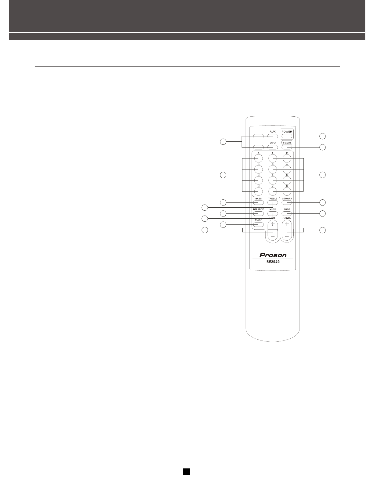
REMOTE CONTROLS
1. Input selector buttons
Press these buttons to select a analog input source.
2.A/B/C/D button
Press the button to select a group of preset stations.
3.BASS Parameter selector button
Press the button to select bass tone. then press
"8" buttons to adjust the low-frequency response.
4.TREBLE Parameter selector button
Press the button to select treble tone. then press
"8" buttons to adjust the high-frequency response.
5.BALANCE Parameter selector button
Press the button to select balance. then press "8"
buttons to adjust the balance between left and right.
6.MUTE
Mute the sound.Press again to restore the audio out
to the previous volume level.
7.SLEEP button
Press the button repeatedly to turn the sleep timer
on and off, and set the sleep time(10-20-30-40-50-
60-70-80-90mins).
8.PARAMETER selected and MASTER VOLUME
adjustment buttons
To adjust parameter selected or main volume.
9.Standby button
Press this button to set this in the standby mode.
Press again turn on the power of this unit.
10.FM/AM band switches button
Press the button to select input source is tuner and
switch the reception band between FM and AM.
11.Number 1-8 button
Press the button to call preset station number on
the tuning status.
12.MEMORY button
Use the button to enter a station to memory.
13.TUNER automatically tuning button
Press and hold the button 3 seconds, All station
are browsed and stored automatically.
(AM/FM is detached)
14.TUNING SCAN+,SCAN- buttons
Press the SCAN+ side to tune in to a higher
frequency.
Press the SCAN- side to tune in to a lower
frequency.
10
1
2
3
4
5
6
7
8
9
12
13
14
11
Page 14
FM AM
COAX LOOP
ANTENNA
VCR
AUX
CD DVD
REC OUT
R
L
R
L
VCR
AUX
CD DVD
REC OUT PRE OUT AMP IN
AUDIO INPUT
R L
PRE OUT AMP IN
R L
AC INLET
MODEL NO.:RV2040
MADE IN CHINA
STEREO RECEIVER AMPLIFIER
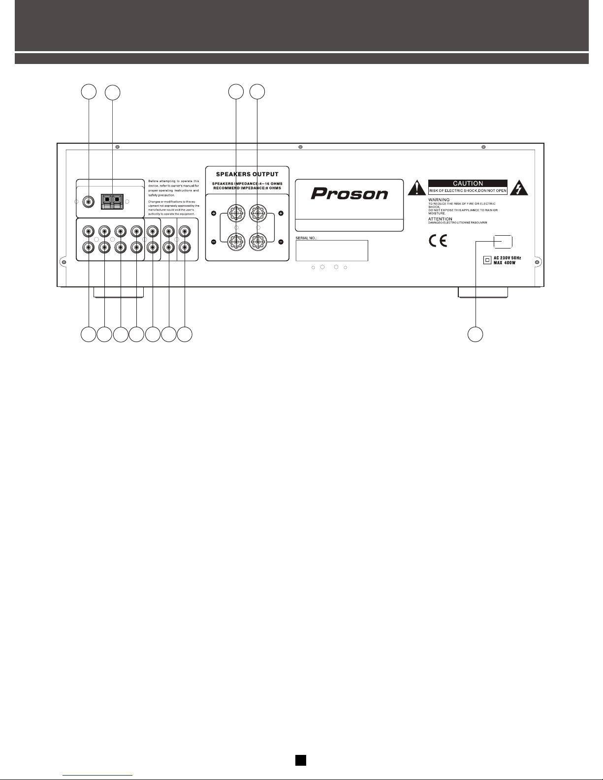
CONNECTING AUXILIARY COMPONENTS
1.FM antenna input
2.AM antenna input
3.Right channel speaker output
4.Left channel speaker output
5.VCR Audio input jacks
6.AUX Audio input jacks
7.CD audio input jacks
8.DVD audio input jacks
9.REC audio output jacks
(The level is controlled by master volume)
10.Pre out jacks
(A short plug is used between 12 and 13 jacks )
11.Amplifier input jacks
(A short plug is used between 12 and 13 jacks )
12.AC 230V/50Hz power input plug
11
33
44
22
55
66
7 7
88 99
1111
1010
1212
11
Page 15

CONNECTING AUXILIARY COMPONENTS
AUDIO
RECEIVER
R
L
199
aivin
aivin
CD
PLAYER
CONNECTING A COMPACT DISC PLAYER
Using one paired (red/white) stereo cable,
connect your new receiver to your compact disc
player as shown to the right.
To play a CD, press CD, put the receiver in CD
mode and press PLAY.
NOTE:
The AUDIO SOURCE connection can be
used as input for any stereo audio signal.
PHONE
A/B/C/D
SCAN+FM/AM
SCAN-
NO.1-8
MEMORY
POWER
VOLUME - VOLUME+
AUTO
INPUT
STEREO RECEIVER AMPLIFIER RV2040
BEFORE YOU CONNECT.....
CONNECTING THE CABLES
-Protect components from power surges.
-Connect all components before plugging power
cords into the wall outlet.
-Always turns off the receiver and/or components
before you connect or disconnect any cables.
-Always make sure the color-coded plugs match
the colour of the terminals in which they are
inserted.
-The connection cable plugs and jacks are
color-coded as follows:
Speaker Terminals Red for positive (+) terminals.
Black for negative (-) terminals.
-Some units may be supplied with connection
plugs that are color-coded red and black instead
of red and white. In this case, the black plug
takes the place of the white plug.
POSITION CABLES CORRECTLY TO AVOID
AUDIO HUM OR INTERFERENCE
-Insert all cable plugs firmly into their jacks.
-Place audio/video cables to the sides of the
receiver's back panel instead of straight down
the middle after you connect the components.
-Try not to coil any power cables and keep them
away from the audio/video cables as much as
possible.
-Make sure all antennas and cables are properly
grounded. Refer to the Safety Tips sheet packed
with your receiver.
12
Page 16

CARE AND MAINTENANCE
No audio
-Make sure the MUTE indicator on the front panel
is off.
-Make sure the speakers are turned on.
-Check the connections.
-Check the short plug between PRE OUT jacks
and AMP IN on the rear panel is inserted.
-Check the power cord connection.
No audio from one channel.
-Check the speaker wire connection or connecting
cable.
-Noise when the TV is turned on, the TV too close
to the audio system.
-Check the connection between the receiver and
the speaker.
The sound does not match the video.
-Press the function button for the video source.
TROUBLESHOOTING TIPS
RECEIVER/TUNER OPERATION
STEREO indicator is off.
-Adjust the antenna.
-The signal is too weak. Connect an external
antenna.
-The signal is Mono.
-Sever hum or noise.
-The signal is too weak. Connect an external
antenna.
REMOTE CONTROL OPERATION
The remote control does not operate the unit.
-Another function is selected on the remote.
Press the correct function button.
-No batteries installed. Install the batteries before
attempting to operate the remote.
Be sure to match the + and ends of each battery
to the symbols shown in the remote battery
compartment.
-The batteries are exhausted. Replace all batteries.
-The remote is not pointed at the remote control
sensor on the main unit or there is an obstacle
between the remote and the main unit.
-The remote control is too far from the main unit
-Move closer.
GENERAL
-Disconnect the system from AC power before
cleaning the exterior of the system with a soft
dust cloth.
CLEANING THE EXTERIOR
13
Page 17

EQUIPMENT SPECIFICATIONS
AMPLIFIER SECTION
Left & Right Channel......................................................................................................2X100Watts
Signal to Noise(A weight)..........................................................................................................85dB
Frequency Response......................................................................................20Hz-20 KHz+/-1.5 dB
AM TUNER SECTION
Frequency Response........................................................................................80Hz 2.3 KHz +/- 6dB
Usable Sensitivity........................................................................................... ....55dBu @ S/N 20 dB
Signal to Noise........................................................................................................................38 dB
Image Ratio......................................................................................................... 30 dB @ 1000KHz
IF Rejection ...........................................................................................................................40 dB
FM TUNER SECTION
Frequency Response......................................................................................... 40Hz-15 KHz+/- 3dB
Quieting................................................................................................................................24 dBu
Signal to Noise....................................................................................... 60 dB (stereo)/65 dB (mono)
Image Ratio..............................................................................................................................40dB
IF Rejection............................................................................................................................. 65dB
Specifications are base on nominal measurements
14
Page 18

R
STEREO RECEIVER AMPLIFIER
RV2040
 Loading...