

Page 1

PXM
PROFIBUS DPV0/DPV1 Master
User Manual
PMEPXM0100
PMEPXM0100H
11/2020
Revision 1.06
Page 2
Preface
DANGER
indicates a hazardous situation which, if not avoided,
will result in
death
or
WARNING
ind
icates a hazardous situation which, if not avoided,
could result in
, death
Note: Before installing, configuring, operating, or maintaining the PMEPXM0100(H)
products, please review this information and the information located on:
https://www.schneider-electric.com/en/product/PMEPXM0100 or
https://www.schneider-electric.com/en/product/PMEPXM0100H
for the latest software, documentation, and installation files specific to the
PMEPXM0100(H) products.
For additional support, please contact Schneider Electric at
https://www.schneider-electric.com/en/work/support/
Installation and maintenance of the PMEPXM0100(H) products should be carried out by
suitably trained personnel in accordance with applicable codes of practice. In case of
malfunction or damage, no attempts of repair should be made. Your PMEPXM0100(H)
product(s) should be returned for repair. Do not dismantle the product.
Notice
Read these instructions carefully and look at the equipment to become familiar with the
device before trying to install, operate, service, or maintain it. The following special messages
may appear throughout this documentation or on the equipment to warn of potential hazards
or to call attention to information that clarifies or simplifies a procedure.
The addition of this symbol to a “Danger” or “Warning” safety label indicates
that an electrical hazard exists which will result in personal injury if the
instructions are not followed.
This is a safety alert symbol. It is used to alert you to potential personal injury
hazards. Obey all safety messages that follow this symbol to avoid possible
injury or death.
DANGER
serious injury.
or serious injury.
Revision 1.06 Page 2 of 238
WARNING
Page 3
Preface
CAUTION
indicates a hazardous situation which, if not avoided,
could result in
minor
NOTICE
is used to address practices not related to physical injury.
UNGUARDED EQUIPMENT
CAUTION
or moderate injury.
NOTICE
PLEASE NOTE
Electrical equipment should be installed, operated, serviced, and maintained only by qualified
personnel. No responsibility is assumed by Schneider Electric for any consequences arising
out of the use of this material.
A qualified person is one who has skills and knowledge related to the construction and
operation of electrical equipment and its installation and has received safety training to
recognize and avoid the hazards involved.
BEFORE YOU BEGIN
Do not use this product on machinery lacking effective point-of-operation guarding. Lack of
effective point-of-operation guarding on a machine can result in serious injury to the operator
of that machine
WARNING
Do not use this software and related automation equipment on equipment
which does not have point-of-operation protection.
Do not reach into machinery during operation.
Failure to follow these instructions can result in death, serious injury, or equipment damage.
This automation equipment and related software is used to control a variety of industrial
processes. The type or model of automation equipment suitable for each application will vary
depending on factors such as the control function required, degree of protection required,
production methods, unusual conditions, government regulations, etc. In some applications,
more than one processor may be required, as when backup redundancy is needed.
Only you, the user, machine builder or system integrator can be aware of all the conditions
and factors present during setup, operation, and maintenance of the machine and, therefore,
can determine the automation equipment and the related safeties and interlocks which can
be properly used. When selecting automation and control equipment and related software
for a particular application, you should refer to the applicable local and national standards
and regulations. The National Safety Council's Accident Prevention Manual (nationally
recognized in the United States of America) also provides much useful information.
Revision 1.06 Page 3 of 238
Page 4

Preface
EQU
IPMENT OPERATION HA
Z
ARD
In some applications, such as packaging machinery, additional operator protection such as
point- of-operation guarding must be provided. This is necessary if the operator's hands and
other parts of the body are free to enter the pinch points or other hazardous areas and serious
injury can occur. Software products alone cannot protect an operator from injury. For this
reason, the software cannot be substituted for or take the place of point-of-operation
protection.
Ensure that appropriate safeties and mechanical/electrical interlocks related to point-ofoperation protection have been installed and are operational before placing the equipment
into service. All interlocks and safeties related to point-of-operation protection must be
coordinated with the related automation equipment and software programming.
NOTE: Coordination of safeties and mechanical/electrical interlocks for point-of-operation
protection is outside the scope of the Function Block Library, System User Guide, or other
implementation referenced in this documentation.
START-UP AND TEST
Before using electrical control and automation equipment for regular operation after
installation, the system should be given a start-up test by qualified personnel to verify correct
operation of the equipment. It is important that arrangements for such a check be made and
that enough time is allowed to perform complete and satisfactory testing
WARNING
Verify that all installation and set-up procedures have been completed.
Before operational tests are performed, remove all blocks or other temporary
holding means used for shipment from all component devices.
Remove tools, meters, and debris from equipment.
Failure to follow these instructions can result in death, serious injury, or equipment damage.
Follow all start-up tests recommended in the equipment documentation. Store all equipment
documentation for future references.
Software testing must be done in both simulated and real environments.
Verify that the completed system is free from all short circuits and temporary grounds that
are not installed according to local regulations (according to the National Electrical Code in
the U.S.A, for instance). If high-potential voltage testing is necessary, follow
recommendations in equipment documentation to prevent accidental equipment damage.
Before energizing equipment:
Remove tools, meters, and debris from equipment.
Revision 1.06 Page 4 of 238
Page 5

Preface
Close the equipment enclosure door.
Remove all temporary grounds from incoming power lines.
Perform all start-up tests recommended by the manufacturer.
OPERATION AND ADJUSTMENTS
The following precautions are from the NEMA Standards Publication ICS 7.1-1995 (English
version prevails):
Regardless of the care exercised in the design and manufacture of equipment or in the
selection and ratings of components, there are hazards that can be encountered if
such equipment is improperly operated.
It is sometimes possible to misadjust the equipment and thus produce unsatisfactory
or unsafe operation. Always use the manufacturer’s instructions as a guide for
functional adjustments. Personnel who have access to these adjustments should be
familiar with the equipment manufacturer’s instructions and the machinery used with
the electrical equipment.
Only those operational adjustments actually required by the operator should be
accessible to the operator. Access to other controls should be restricted to prevent
unauthorized changes in operating characteristics.
For professional users in the European Union
If you wish to discard electrical and electronic equipment (EEE), please contact your
dealer or supplier for further information.
Revision 1.06 Page 5 of 238
Page 6

Preface
POSSIBLE HOT SURFACE
North American Hazardous Location Approval
SUITABLE FOR USE IN CLASS I, DIVISION 2, GROUPS A, B, C AND D HAZARDOUS LOCATIONS, OR
NONHAZARDOUS LOCATIONS ONLY.
WARNING - EXPLOSION HAZARD - DO NOT DISCONNECT EQUIPMENT WHILE THE CIRCUIT IS LIVE
OR UNLESS THE AREA IS KNOW TO BE FREE OF IGNITABLE CONCENTRATIONS.
WARNING - EXPLOSION HAZARD - SUBSTITUTION OF ANY COMPONENT MAY IMPAIR SUITABILITY
FOR CLASS I, DIVISION 2.
ADAPTÉ POUR UNE UTILISATION EN CLASSE 1, DIVISION 2, GROUPES A, B, C ET D LIEUX
DANGEREUX OU EXCLUSIVEMENT EMPLACEMENT NON DANGEREUX
AVERTISSEMENT - RISQUE D'EXPLOSION - NE PAS DECONNECTER L'EQUIPEMENT LORSQUE LE
CIRCUIT EST ALIMENTE, A MOINS QUE LA ZONE SOIT CONTROLEE ABSENTE DE CONCENTRATION
INFLAMMABLES.
AVERTISSEMENT - RISQUE D'EXPLOSION - REMPLACEMENT DE TOUT COMPOSANT PEUT NUIRE A
LA CONFORMITÉ DE CLASS I, DIVISION 2.
ATEX Warnings and Conditions of Safe Usage
Power, Input, and Output (I/O) wiring must be in accordance with the authority having
jurisdiction.Warning - Explosion Hazard - When in hazardous locations, turn off power before
replacing or wiring modules.
Warning - Explosion Hazard - Do not disconnect equipment unless power has been switched off
or the area is known to be non-hazardous.
These products are intended to be mounted in an IP54 enclosure. The devices shall provide
external means to prevent the rated voltage being exceeded by transient disturbances of more
than 40%. This device must be used only with ATEX certified backplanes.
DO NOT OPEN WHEN ENERGIZED.
CAUTION
Certain surfaces may be hot.
Failure to follow these instructions can result in injury or equipment damage.
Revision 1.06 Page 6 of 238
Page 7

China RoHS Declaration Table
部件名称
Part Name (Pb) (Hg) (Cd) (Cr (VI)) (PBB) (PBDE)
金属部件
Metal parts
塑料部件
Plastic parts
电子件
Electronic
触点
Contacts
线缆和线缆附件
Cables &
cabling
accessories
铅
X O O O O O
O O O O O O
O O O O O O
O O X O O O
X O O O O O
Preface
有害物质 - Hazardous Substances
汞
镉 六价铬
多溴联
苯
多溴二苯
醚
本表格依据 SJ/T11364 的规定编制。
O: 表示该有害物质在该部件所有均质材料中的含量均在 GB/T 26572 规定的限量要求以下。
X: 表示该有害物质至少在该部件的某㇐均质材料中的含量超出 GB/T 26572 规定的限量要求。
This table is made according to SJ/T 11364.
O: Indicates that the concentration of hazardous substance in all of the homogeneous materials
for this part is below the limit as stipulated in GB/T 26572.
X: Indicates that concentration of hazardous substance in at least one of the homogeneous
materials used for this part is above the limit as stipulated in GB/T 26572.
Revision 1.06 Page 7 of 238
Page 8

Preface
CONTENTS
1. Preface ............................................................................................................................. 15
1.1. Introduction to the PXM ........................................................................................ 15
1.2. Prerequisites .......................................................................................................... 15
1.3. Features ................................................................................................................. 15
1.4. Architecture ........................................................................................................... 16
1.5. Additional Information .......................................................................................... 18
1.6. Support .................................................................................................................. 19
2. Installation ....................................................................................................................... 20
2.1. Module Layout ....................................................................................................... 20
2.2. Module Mounting .................................................................................................. 21
2.3. Backplane Connector ............................................................................................. 23
2.4. PROFIBUS DP Port (RS485) .................................................................................... 23
3. Setup ................................................................................................................................ 24
3.1. Setup Introduction ................................................................................................. 24
3.2. Install Configuration Software ............................................................................... 24
3.3. Network Parameters ............................................................................................. 25
3.4. GSD File Management ........................................................................................... 25
3.5. PXM Type Library ................................................................................................... 28
3.5.1. Compatibility ...................................................................................................... 28
3.5.2. Installation ......................................................................................................... 28
3.5.3. Updating Project ................................................................................................ 30
3.5.4. Mandatory Settings in Control Expert ............................................................... 31
3.5.5. Library Content .................................................................................................. 31
3.6. Creating a New Project .......................................................................................... 32
3.7. PXM Parameters .................................................................................................... 35
Revision 1.06 Page 8 of 238
Page 9

Preface
3.7.1. General ............................................................................................................... 35
3.7.2. PROFIBUS ........................................................................................................... 40
3.7.3. HSBY ................................................................................................................... 43
3.7.4. Security .............................................................................................................. 45
3.7.5. SNMP .................................................................................................................. 48
3.7.6. Time ................................................................................................................... 48
3.8. Verify Configuration .............................................................................................. 49
3.9. Module Download ................................................................................................. 51
3.10. Device Discovery (Online) ...................................................................................... 52
3.10.1. Discovery ........................................................................................................ 52
3.10.2. Device Station Address Change...................................................................... 55
3.11. Adding PROFIBUS DP Devices ................................................................................ 56
3.11.1. General ........................................................................................................... 57
3.11.2. PROFIBUS Configuration ................................................................................ 58
3.11.3. DPV1 ............................................................................................................... 61
3.11.4. User Parameters ............................................................................................. 62
3.11.5. Slot Configuration .......................................................................................... 63
3.11.6. Start-up Parameters ....................................................................................... 66
3.11.7. Mapping Report ............................................................................................. 67
3.12. PROFIBUS Device Bulk Instantiation ...................................................................... 68
3.12.1. Copy, Paste and Paste Special ........................................................................ 68
3.12.2. Import / Export Device Lists ........................................................................... 70
3.13. Control Expert Configuration................................................................................. 71
3.13.1. Configure Project Settings .............................................................................. 71
3.13.2. Instantiate PXM (Placeholder) ....................................................................... 72
3.13.3. Instantiate PXM DTM (Generic EDS) .............................................................. 73
3.13.4. Modifying PXM IP address ............................................................................. 75
3.13.5. Modifying PXM Connection Settings.............................................................. 77
3.13.6. PXM RPI Recommendations ........................................................................... 79
3.13.7. PXM Mapping Export/Import for Control Expert ........................................... 79
3.13.8. Download to M580 Controller ....................................................................... 83
Revision 1.06 Page 9 of 238
Page 10

Preface
3.13.9. Control Expert Project Clean-up .................................................................... 84
4. Operation ......................................................................................................................... 87
4.1. PROFIBUS DP ......................................................................................................... 87
4.2. Control Expert Connection .................................................................................... 87
4.3. Control Expert Mapping ........................................................................................ 88
4.3.1. PXM Master DDT (T_PXM_Master) ................................................................... 88
4.3.2. Device DDT ......................................................................................................... 93
4.3.3. Master Mapping DFB ......................................................................................... 97
4.3.4. Device Mapping DFB .......................................................................................... 99
4.4. Change Configuration on the Fly (CCOTF) ........................................................... 100
4.5. Explicit Messaging Function Blocks ..................................................................... 102
4.5.1. ID DFB ............................................................................................................... 103
4.5.2. RDRec DFB ........................................................................................................ 109
4.5.3. WRRec DFB ....................................................................................................... 111
4.5.4. RDDiag DFB ...................................................................................................... 114
4.5.5. RDAlarm DFB .................................................................................................... 116
4.5.6. GlobalControl DFB ............................................................................................ 119
4.6. Explicit Messaging Utility ..................................................................................... 123
4.7. Global Control Utility ........................................................................................... 126
4.8. DPV1 Communication .......................................................................................... 127
4.8.1. Class 1 Messaging (MS1) .................................................................................. 127
4.8.2. Class 2 Messaging (MS2) .................................................................................. 129
4.9. Diagnostics ........................................................................................................... 134
4.9.1. Notification ...................................................................................................... 135
4.9.2. Extraction ......................................................................................................... 137
4.10. Global Control ...................................................................................................... 139
4.11. Alarming ............................................................................................................... 140
4.11.1. Notification ................................................................................................... 140
4.11.2. Extraction ..................................................................................................... 143
Revision 1.06 Page 10 of 238
Page 11

Preface
4.12. Fast Device Replacement (FDR) ........................................................................... 144
4.13. Firmware upgrading ............................................................................................ 145
5. HSBY ............................................................................................................................... 148
5.1. Introduction ......................................................................................................... 148
5.2. PXM in HSBY ........................................................................................................ 148
5.2.1. Controlled SWAP .............................................................................................. 151
5.2.2. Uncontrolled SWAP ......................................................................................... 152
5.3. Configuration ....................................................................................................... 153
5.3.1. HSBY Holdover ................................................................................................. 155
5.3.1. HSBY DP Deadtime ........................................................................................... 156
5.3.2. HSBY Switch Over Command Rate ................................................................... 156
5.3.3. HSBY Switch Over Retry Limit .......................................................................... 156
5.4. Download Configuration ..................................................................................... 157
5.5. Control Expert Setup ........................................................................................... 158
5.6. Operation ............................................................................................................. 159
5.6.1. Control Expert Operation ................................................................................. 159
5.6.2. Manual SWAP on PXM Unrecoverable Hardware Error .................................. 159
5.7. Diagnostics ........................................................................................................... 159
5.7.1. ProSoft Configurator for Modicon Diagnostics ................................................ 159
6. Migrating PTQ-PDPMV1 Projects ................................................................................... 161
7. Device Type Manager (DTM) ......................................................................................... 165
7.1. Installation ........................................................................................................... 165
7.2. Configuration ....................................................................................................... 165
7.1. Operation ............................................................................................................. 168
8. Diagnostics ..................................................................................................................... 172
8.1. LEDs...................................................................................................................... 172
8.2. Module Status Monitoring .................................................................................. 174
8.2.1. PXM DP Master ................................................................................................ 174
8.2.2. Device Status .................................................................................................... 189
Revision 1.06 Page 11 of 238
Page 12

Preface
8.3. PROFIBUS Packet Capture ................................................................................... 196
8.4. Target Browser .................................................................................................... 200
8.5. Module Event Log ................................................................................................ 203
8.6. Web Server .......................................................................................................... 203
9. Troubleshooting Guide .................................................................................................. 205
10. Technical Specifications .............................................................................................. 207
10.1. Dimensions .......................................................................................................... 207
10.2. Electrical .............................................................................................................. 207
10.3. PROFIBUS DP ....................................................................................................... 208
10.4. Certifications ........................................................................................................ 208
11. PROFIBUS DP ............................................................................................................... 209
11.1. Introduction ......................................................................................................... 209
11.2. PROFIBUS master and slave ................................................................................ 210
11.3. PROFIBUS master class 1 (DPM1) or class 2 (DPM2) ........................................... 210
11.4. Cyclic communication .......................................................................................... 211
11.5. Acyclic communication ........................................................................................ 211
11.6. Topology of PROFIBUS DP ................................................................................... 212
11.7. PROFIBUS DP cable description ........................................................................... 212
11.8. PROFIBUS DP connector description ................................................................... 213
12. Appendix ..................................................................................................................... 214
12.1. DPV1 Response Status ......................................................................................... 214
12.2. DPV1 Extended Status Codes .............................................................................. 214
12.3. SysLog Events ....................................................................................................... 216
12.4. Verification Notifications ..................................................................................... 219
12.5. Additional CIP Objects ......................................................................................... 220
12.5.1. PXM General Status...................................................................................... 220
12.5.2. PXM Master Statistics .................................................................................. 223
Revision 1.06 Page 12 of 238
Page 13

Preface
12.5.3. Profibus End-Point Diagnostic Admin ......................................................... 225
12.5.4. Profibus End-Point Diagnostic ...................................................................... 226
12.5.5. Profibus End-Point Statistics Admin ............................................................. 227
12.5.6. Profibus End-Point Statistics ........................................................................ 227
12.5.7. Profibus Data Exchange Admin .................................................................... 229
12.5.8. Profibus Data Exchange ................................................................................ 229
12.5.9. EtherNet/IP Connection Diagnostics ............................................................ 230
12.5.10. EtherNet/IP IO Message Diagnostics ........................................................... 231
12.5.11. EtherNet/IP Explicit Message Diagnostics ................................................... 231
12.5.12. EtherNet/IP Communication Capacity ......................................................... 232
12.5.13. EtherNet/IP Bandwidth Diagnostics ............................................................. 233
12.5.14. IO Connection Diagnostic ............................................................................. 233
12.5.15. IO Connection Information .......................................................................... 234
12.5.16. IO Connection Diagnostics ........................................................................... 235
12.5.17. Explicit Connection Diagnostic ..................................................................... 236
13. Index ............................................................................................................................ 237
Revision 1.06 Page 13 of 238
Page 14

Preface
Revision History
Revision Date Comment
1.03 17 April 2019 Initial release
1.04 28 August 2019 Added PCM Enhanced IO Scan Option in EcoStruxure Control Expert Export.
1.05 9 January 2020 Added timing diagram detail for Freeze and Sync Global Controls.
Added note on manual HSY SWAP on PXM disconnection / unrecoverable
hardware error.
Added Control Expert Project Clean-Up recommendations (3.13.9)
Added Set Watchdog All option (3.11.2)
Added HSBY Master Mapping Timing Diagram (Figure 4.4)
Updated non-interfering Safety description (1.3)
1.06 17 November 2020 Added Project Properties (3.6)
Additional Slot configuration information (3.11.5)
Updated LiveList definition in Control Expert DDT (4.3.1.1)
Added PROFIBUS Capture functionality (8.3)
Added Auto Recommend description (Table 3.4)
Updated Default Watchdog description (Table 3.4 and Table 3.11)
Updated FDR Config Retrieval Status (Table 8.4)
Revision 1.06 Page 14 of 238
Page 15

Preface
1. PREFACE
1.1. INTRODUCTION TO THE PXM
This manual describes the installation, operation, and diagnostics of the ProSoft PXM
PROFIBUS DPV0/DPV1 Master – PMEPXM0100 or PMEPXM0100H. The PXM allows the user
to integrate PROFIBUS DP slave devices into Schneider Electric’s M580 Control System. This
will allow the M580 Control System to exchange process, alarming, and diagnostic data with
PROFIBUS DP devices as well as provide parameterization and asset management of slave
devices using Device Type Managers (DTMs).
1.2. PREREQUISITES
The PXM module operates in the M580 System with following requirements:
EcoStruxure Control Expert: V14 or greater
(+ ControlExpert_V140_HF_PMEPXM0100 hotfix)
M580 CPU Firmware: 2.80 or greater
1.3. FEATURES
The PXM can exchange process data (DPV0) with up to 125 PROFIBUS DP slave devices which
will be formatted into the engineering units in the M580 Control System by using the
automatically generated Control Expert mapping imports.
The ProSoft Configurator for Modicon will allow the user to configure each PXM as well as
each PROFIBUS DP slave device connected to the PXM for DPV0 communication. The utility
will also automatically generate the mapping routines and structures (in either Function Block
or Structured Text) which can be imported into Control Expert.
The PXM also provides DPV1 communication allowing the user to exchange DPV1 Class 1 and
Class 2 data with each slave device. The PXM Gateway DTM can be used to configure and
parameterize each slave device using Device Type Manager (DTM) technology.
The PXM will allow the user to monitor and extract DPV1 alarms from each slave device on
the connected PROFIBUS DP fieldbus from the M580 controller.
The PXM provides a range of statistics and tools to provide a detailed diagnostic overview of
each PXM which speeds-up system commissioning. The Configuration Utility allows the user
to do a PROFIBUS DP packet capture of the running fieldbus which can be used to analyse the
Revision 1.06 Page 15 of 238
Page 16

Preface
bus behaviour and packets received. The PXM also provides global and device specific
statistics.
Each PXM connection to the M580 controller can be customized to the required data size.
This provides the user with a range of EtherNet/IP connection sizes and counts to limit the
amount of memory used by each PXM.
The PXM also allows the user to customize the required security level for an application by
enabling or disabling certain protocols as well as having a configurable Access Control List. In
addition to this the PXM can log up to 2048 events into non-volatile memory (NV) which can
later be offloaded to a SysLog Server.
The PXM can be used in one of two modes; Standalone or HSBY.
Standalone
In this mode a single PXM is connected a single M580 controller. The PXM can be run in the
local rack or a remote rack (using either the controller connection or NOC).
HSBY
In this mode the PXM can be used in a redundant M580 Control Architecture. Each PXM will
be located in the local rack of each redundant M580 controller. This will allow the PXM to
switch with the M580 controllers in an HSBY system when needed. The PXM will provide a
bumpless transfer when switching from Primary PXM to Standby PXM when a switch over
event occurs.
Safety
The module can be installed in the same rack as safety modules, as it is a non-interfering type
1 device.
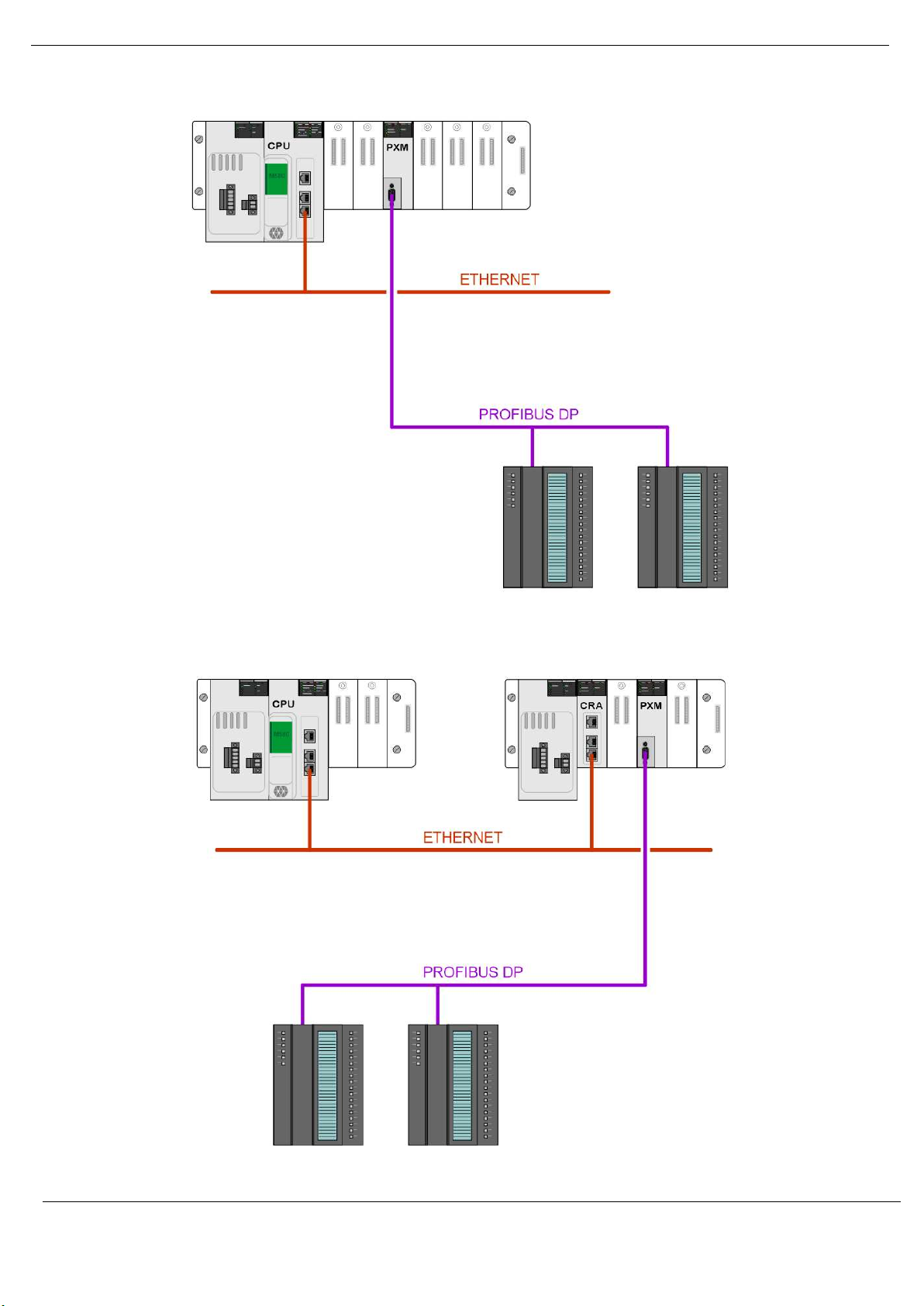
1.4. ARCHITECTURE
The PXM can be configured to operate in one of three architectures; Standalone, HSBY, or
Remote.
The figure below provides an example of the typical network setup in a Standalone
architecture.
Revision 1.06 Page 16 of 238
Page 17
Preface
Figure 1.1 - PXM Standalone architecture
Alternatively, the PXM can be configured to operate in a Remote Rack of the M580 system.
Figure 1.2 - PXM Standalone architecture in a Remote Rack
Revision 1.06 Page 17 of 238
Page 18
Preface
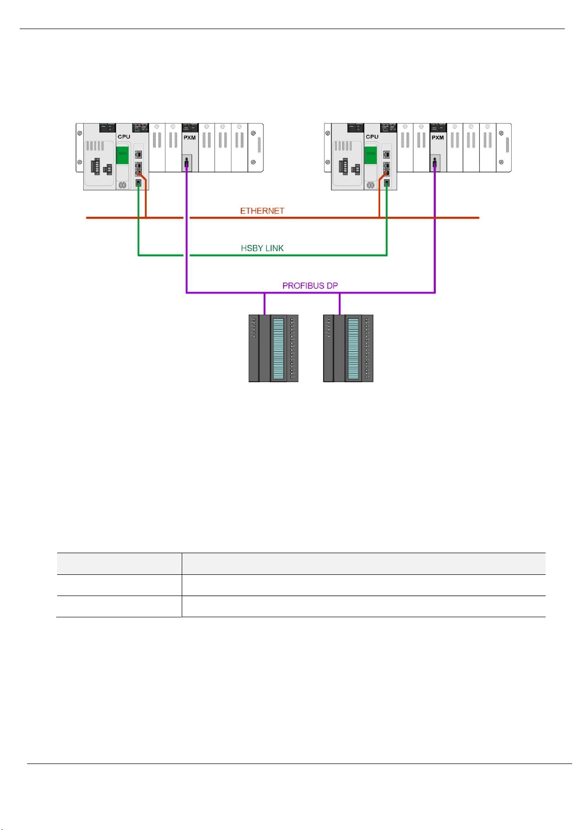
When the M580 control system is operating in a redundant HSBY architecture, each PXM will
operate in the local rack as shown below:
Figure 1.3 - PXM HSBY architecture
1.5. ADDITIONAL INFORMATION
The following web sites contain additional information that can assist the user with the
module installation and operation, including the required ProSoft Configurator for Modicon
configuration software.
Resource Link
PMEPXM0100
PMEPXM0100H
https://www.schneider-electric.com/en/product/PMEPXM0100
https://www.schneider-electric.com/en/product/PMEPXM0100H
Table 1.1 - Additional Information
Revision 1.06 Page 18 of 238
Page 19

Preface
1.6. SUPPORT
Technical support is provided via the Web (in the form of user manuals, FAQ, datasheets etc.)
to assist with installation, operation, and diagnostics.
For additional support the user can use either of the following:
Resource Link
Contact Us web link https://www.schneider-electric.com/en/work/support/
Table 1.2 – Support Details
Revision 1.06 Page 19 of 238
Page 20
Installation
2. INSTALLATION
2.1. MODULE LAYOUT
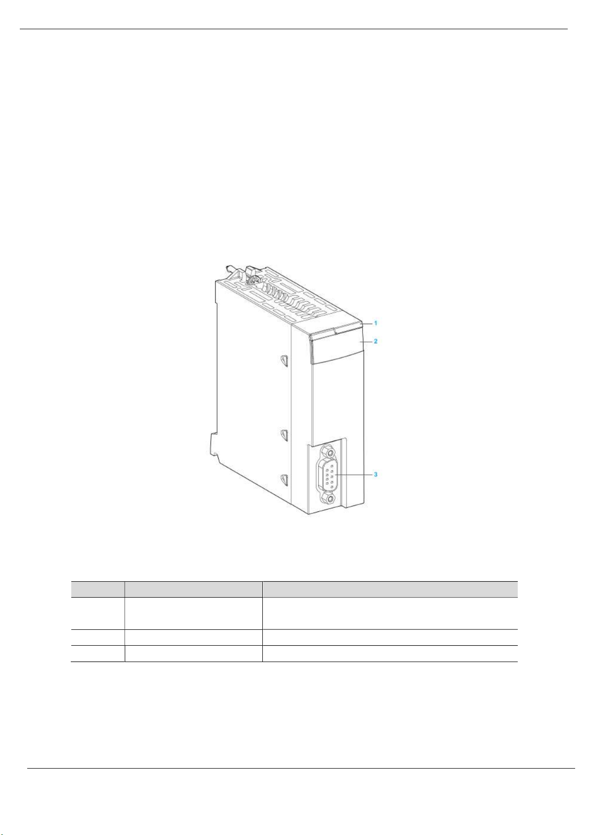
The PXM has one RS485 PROFIBUS DP port at the front of the module and one M580
backplane port at the back of the module, as shown in the figure below. The front port is used
to connect to the PROFIBUS DP fieldbus and the backplane port is used to connect to the
M580 backplane. All the required power is derived from the M580 backplane.
Figure 2.1 - PXM Front and Side view
Number Element Function
1 Module name
2 LED array LED indication to diagnose the module
3 SUB-D 9 female connector PROFIBUS DP Port
Table 2.1 – Module layout
The module provides seven diagnostic LEDs as shown in the front view figure below. These
LEDs are used to provide information regarding the module system operation, the Backplane
Revision 1.06 Page 20 of 238
ePXM0100 (Standard)
ePXM0100H (Harsh)
Page 21
Installation
interface, and the PROFIBUS DP fieldbus interface. See the Diagnostics section for details on
each LED state.
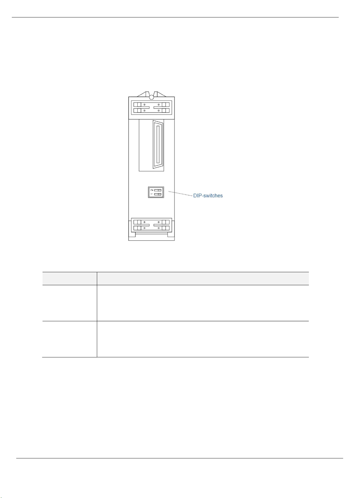
The module provides two DIP-switches at the back of the enclosure as shown in the figure
below.
Figure 2.2 - PXM Back view
DIP Switch Description
DIP Switch 1 This DIP switch is used to reject the configuration in NV memory as well as the
configuration received from the Head module (using TFTP). This action resets the
module to Factory Defaults. The module will then wait for new configuration to be
downloaded to it.
DIP Switch 2 Used to force the module into “Safe Mode”. When in “Safe Mode” the module will not
load the application firmware and will wait for new firmware to be downloaded. This
should only be used in the rare occasion when a firmware update was interrupted at
a critical stage.
Table 2.2 - DIP Switch Settings
2.2. MODULE MOUNTING
The PXM module will connect directly to the M580 backplane. Note that it does not use the
X80 backplane connector and will only power up on an Ethernet backplane. In an M580
architecture, you can mount the PXM module on a local rack or a remote drop.
Revision 1.06 Page 21 of 238
Page 22
Installation
EQUIPMENT DAMAGE
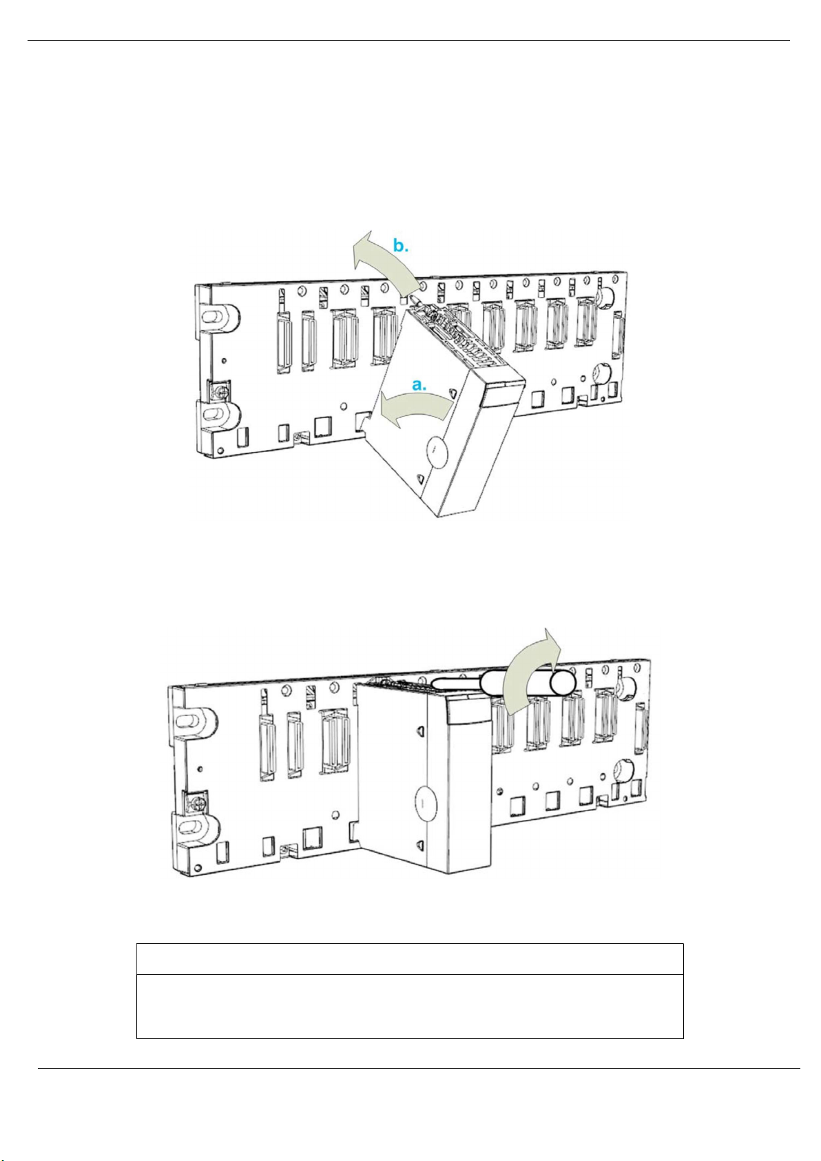
Follow the step below to mount the module on the backplane:
a. Insert the locating pins on the bottom of the module into the corresponding slots in
the rack.
b. Use the locating pins as a hinge and pivot the module until it is flush with the rack.
(The twin connector on the back of the module inserts the connectors on the rack).
Figure 2.3 – Mounting the PXM to the backplane
Tighten the retaining screw to hold the module in place on the rack:
Figure 2.4 – Tightening the PXM to the backplane
Revision 1.06 Page 22 of 238
NOTICE
The maximum tightening torque is 1.5 Nm (1.11 lb-ft).
Failure to follow these instructions may result in equipment damage.
Page 23
Installation
2.3. BACKPLANE CONNECTOR
The Ethernet bus interface at the back of the PXM module connects to the Ethernet backplane
connector when you mount the module in the rack (see Module Mounting section). The
module is powered by the backplane. It is hot swappable, that is, it may be installed and
uninstalled without turning off the power supply to the rack.
The X Bus connector of the backplane is not present nor required. The module uses the
Ethernet bus on the Ethernet backplane to manage the connectivity to the Ethernet I/O
scanner.
The module communicates with a PC that is connected to the Ethernet network using an asset
management, a network manager, or a web browser.
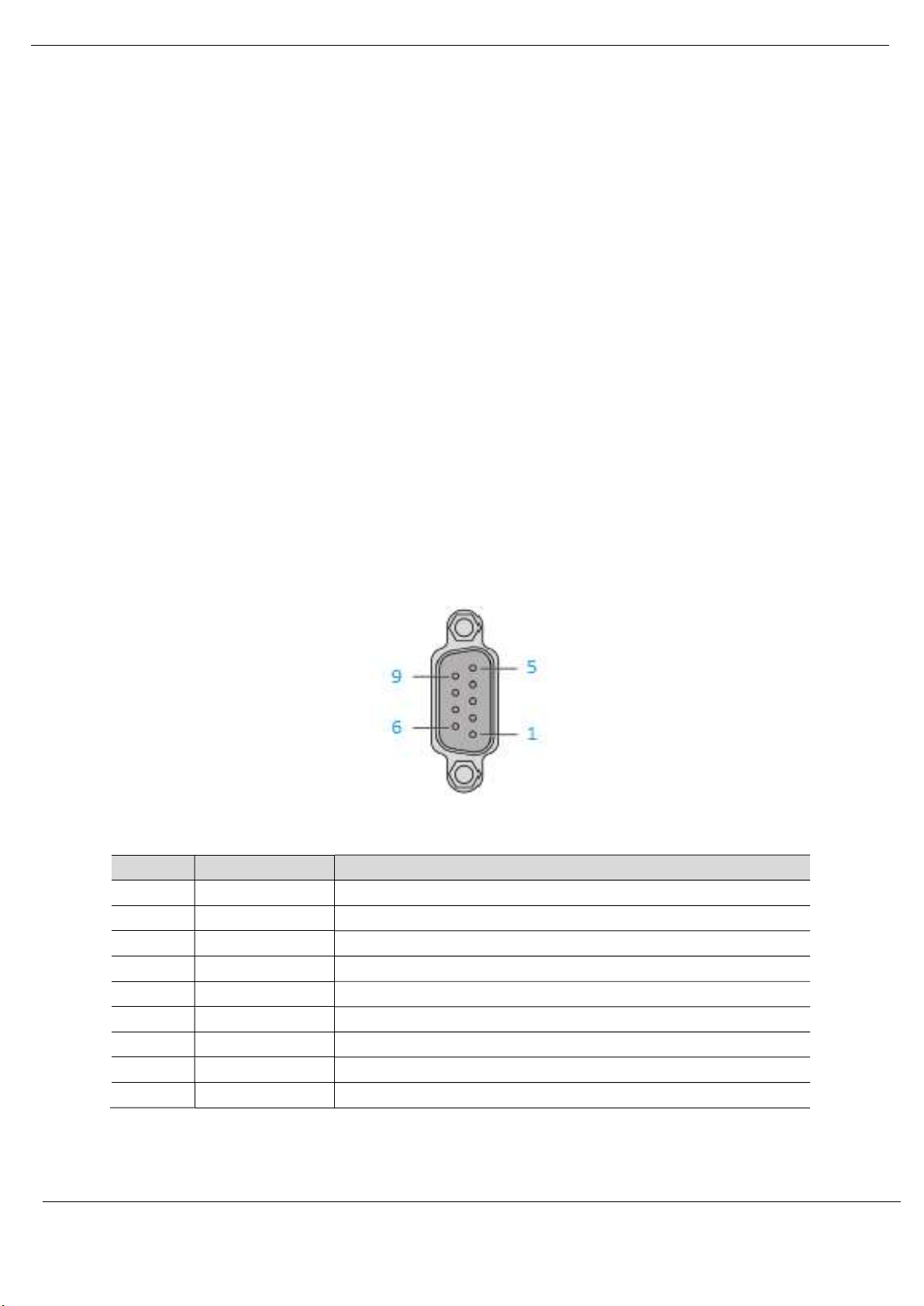
2.4. PROFIBUS DP PORT (RS485)
The PROFIBUS DP port uses a female DB9 connector. This provides connection for the
communication conductors, cable shielding and +5Vdc output power.
Figure 2.5 - PXM PROFIBUS DP (RS485) DB9 connector
Pin Signal Description
1 - Not connected
2 - Not connected
3 RxD/TxD-P Data received and transmit (+)
4 CNTR-P Control signal to repeater (+)
5 DGND Reference potential for +5Vdc
6 VP +5Vdc for terminating resistors (active termination)
7 - Not connected
8 RxD/TxD-N Data received and transmit (-)
9 - Not connected
Table 2.3 – DB 9 Connector layout
Revision 1.06 Page 23 of 238
Page 24
Setup
3. SETUP
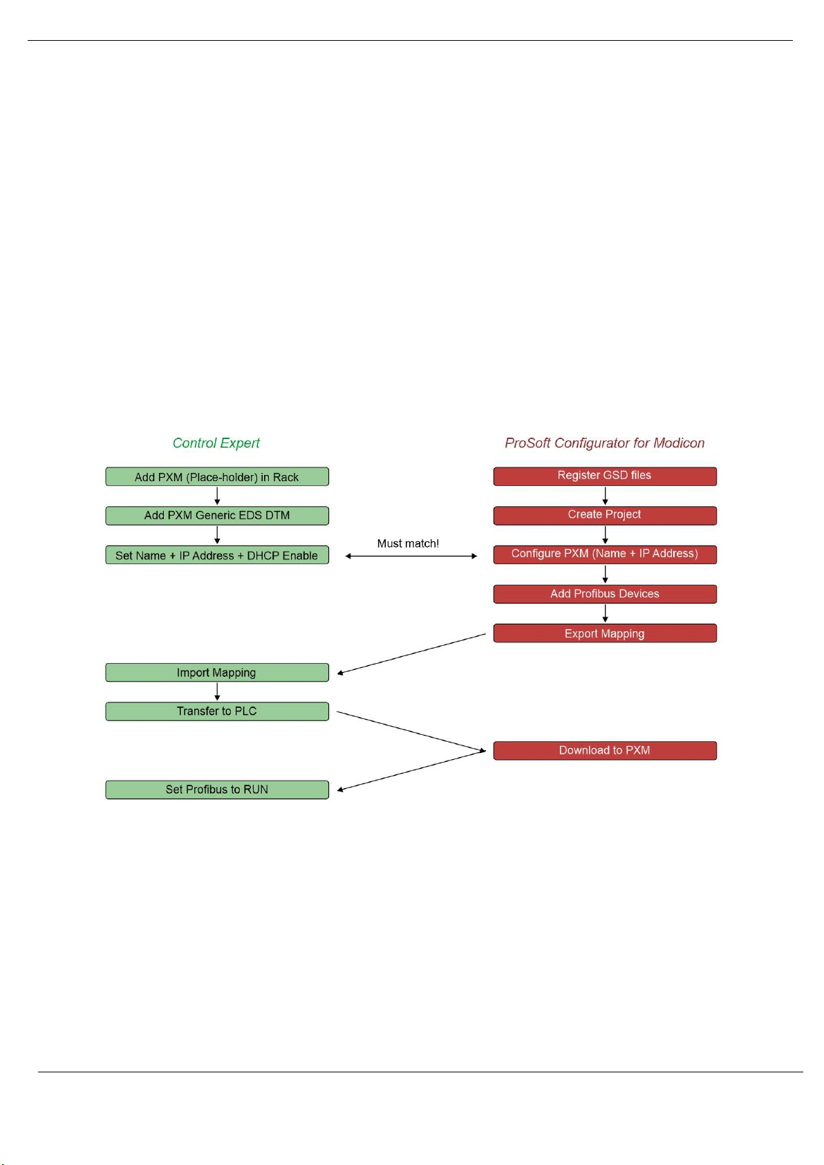
3.1. SETUP INTRODUCTION
The setup of the PXM requires configuration in both Control Expert and the ProSoft
Configurator for Modicon (PCM).
The figure below provides an overview of the required steps to configure a new PXM module.
Although it is not important whether the user starts with the Control Expert configuration or
the PCM configuration, it is important that the Control Expert configuration is transferred to
the M580 controller, before the PXM can be downloaded.
Figure 3.1 – PXM Configuration Overview
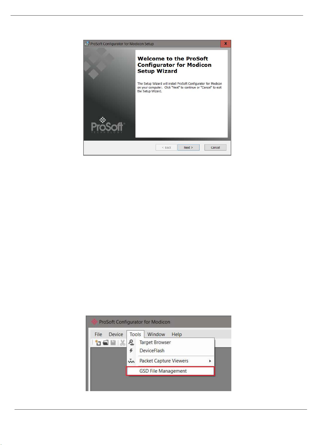
3.2. INSTALL CONFIGURATION SOFTWARE
All the PROFIBUS network setup and configuration of the PXM module is achieved by means
of the ProSoft Configurator for Modicon.
Revision 1.06 Page 24 of 238
Page 25
Setup
Figure 3.2 - ProSoft Configurator for Modicon Installation
3.3. NETWORK PARAMETERS
The module Ethernet network parameters (e.g. IP address) will be managed by the Head
module in the local M580 rack. See the Control Expert Configuration section.
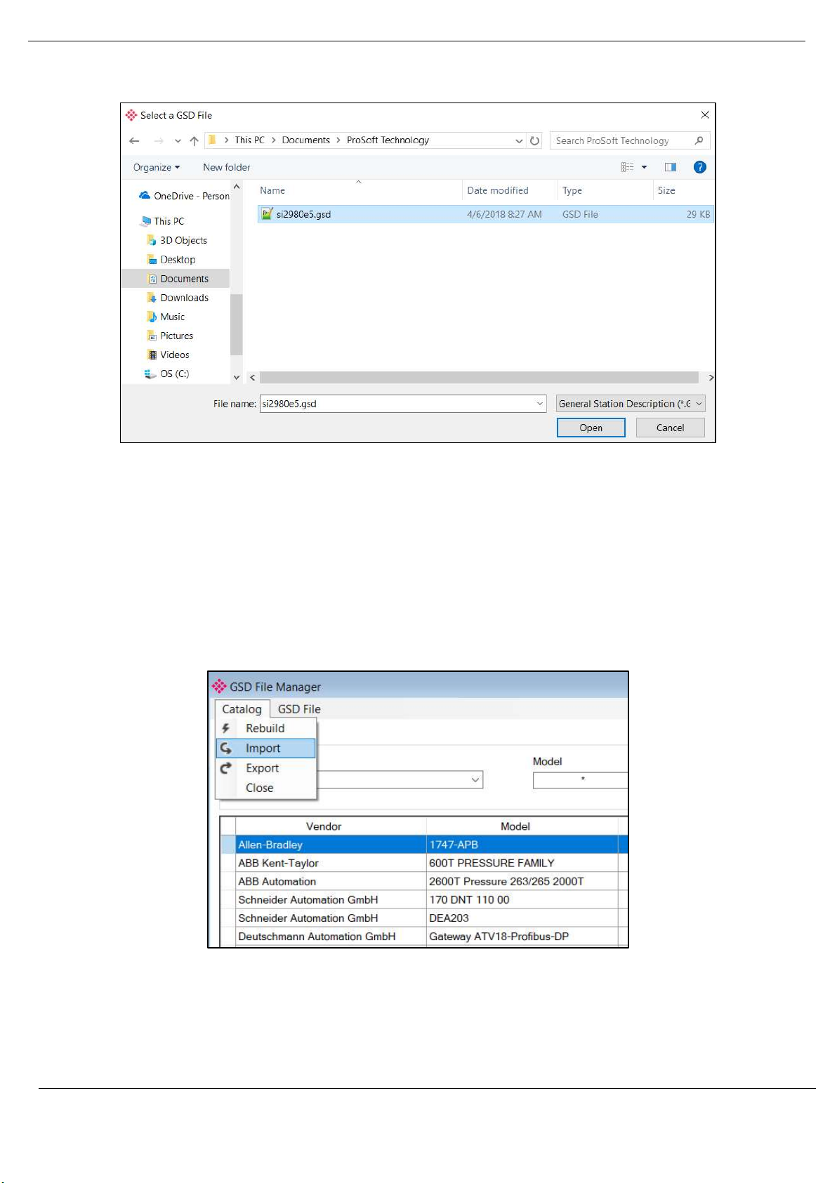
3.4. GSD FILE MANAGEMENT
Each PROFIBUS device has a GSD file that is required to provide information needed to
configure the device for data exchange. The ProSoft Configurator for Modicon manages the
GSD library which is used for adding devices to the PXM.
The GSD File Management Tool is opened by selecting GSD File Management under the Tool
menu in the configuration utility.
Figure 3.3 – Launching the GSD File Management Tool
Revision 1.06 Page 25 of 238
Page 26

Setup
Once the tool has been opened a list of slave devices already registered using their GSD files.
Figure 3.4 – GSD File Management Tool
To add a GSD file the user will need to select the Add option under the GSD File menu.
Figure 3.5 – GSD File Adding
The required GSD file will need to be selected as shown below:
Revision 1.06 Page 26 of 238
Page 27
Setup
Figure 3.6 – GSD File Adding
Once the file has been selected the GSD File Management tool will add the slave device to the
device list and recompile the GSD catalog.
A GSD catalog can be reused by another ProSoft Configurator for Modicon by exporting the
GSD catalog on one ProSoft Configurator for Modicon and importing it in another. This is done
by selecting either Import or Export under the Catalog menu as shown below:
Figure 3.7 – GSD Catalog importing
Revision 1.06 Page 27 of 238
Page 28
Setup
3.5. PXM TYPE LIBRARY
The PXM requires the use of a number of system DFBs and DDTs. These are contained
within the PXM Type Library which must be registered before using a PXM in a Control
Expert application.
3.5.1. COMPATIBILITY
The PXM Type Library has the following minimum requirements:
• EcoStruxure Control Expert: V14 or greater
• M580 CPU Firmware: 2.80 or greater
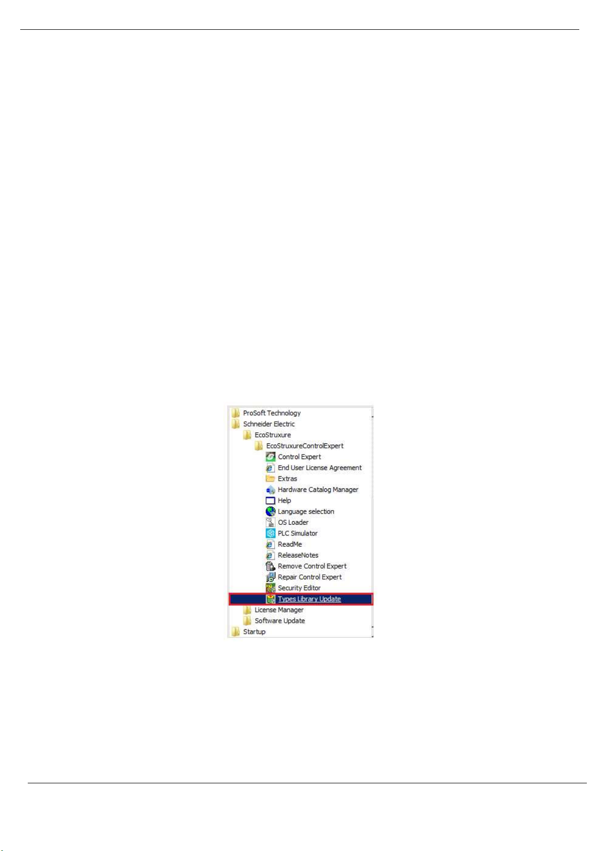
3.5.2. INSTALLATION
Download the PXM Type Library and unzip it to a suitable folder.
In the Windows Start menu, under the Schneider Electric … EcoStruxure, select the Types
Library Update item.
Figure 3.8 – Launch Type Library Update utility
Revision 1.06 Page 28 of 238
Page 29
UNEXPECTED BEHAVIOUR
NOTICE
A Type Library cannot be registered if Control Expert is running. Be sure to close
Control Expert before starting this process.
Failure to follow these instructions may result in an unexpected behaviour.
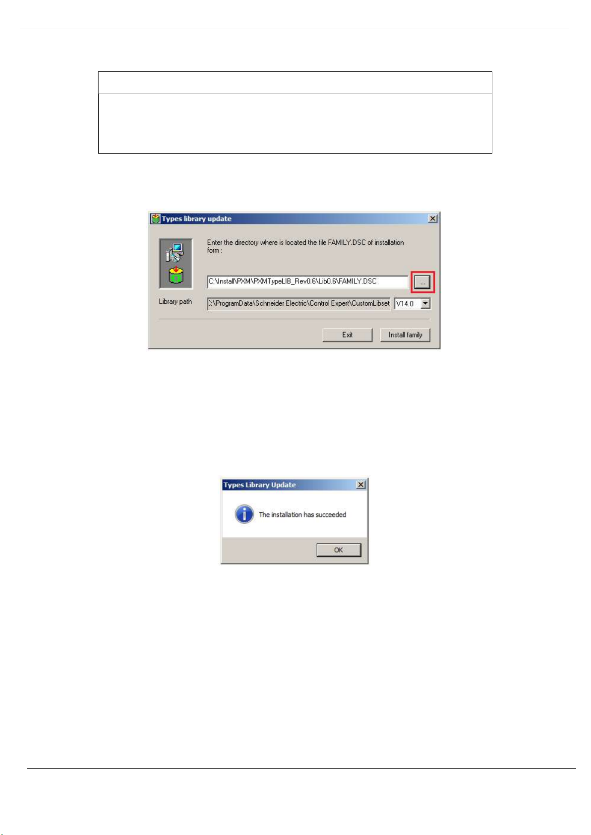
The Types Library Update utility will open.
Setup
Figure 3.9 – Type Library Update utility
Use the Browse button (“…”) to navigate to the Family.dsc file in the PXM Type Library
folder. Then click Ok.
The successfully registration will then be indicated by the following prompt:
Figure 3.10 – PXM Type Library Installation Succesful
The imported library can be viewed in Control Expert by selecting the Types Library Manager
item under the Tools menu. In the Type Library Manager, select the PMEPXM folder which
can be found in the following folder:
<LibsetV14.0>\Profibus
Revision 1.06 Page 29 of 238
Page 30
Setup
Figure 3.11 – Type Library Manager – PXM
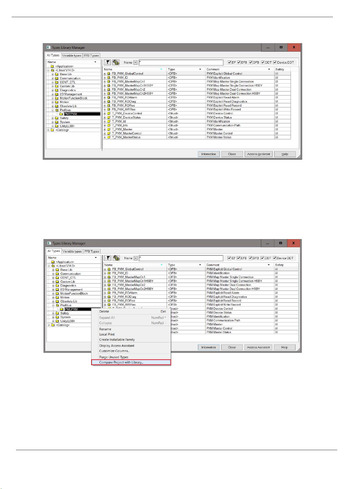
3.5.3. UPDATING PROJECT
If a newer revision of the PXM Type Library is installed, then the existing project will need to
be updated. To update the project, open the Types Library Manager item under the Tools
menu. Right-click on the PMEPXM folder and select the Compare Project with Library option.
Figure 3.12 – Type Library Manager – Compare with project
The Library Version Management window will open showing any differences between the
project and the updated PXM Type Library. To update, select the Update All button.
Revision 1.06 Page 30 of 238
Page 31

Setup
Figure 3.13 – Type Library Manager – Update Project
3.5.4. MANDATORY SETTINGS IN CONTROL EXPERT
Any project making use of the PXM Type Library must have the Allow Dynamic Arrays option
enabled.
This can be enabled by selecting the Project Settings option under the Control Expert Tools
menu. In the Project Settings window, select the Variables left menu item and then check the
Allow Dynamic Arrays (ANY_ARRAY_XXX) option.
Figure 3.14 – Project Settings
3.5.5. LIBRARY CONTENT
The PXM Type Library contains the following:
Type DFB Description
DFB FB_PXM_MasterMapCn1 Master Mapping for Standalone Single Connection
FB_PXM_MasterMapCn2
FB_PXM_MasterMapCn1HSBY Master Mapping for HSBY Single Connection
Revision 1.06 Page 31 of 238
Master Mapping for Standalone Dual Connection
Page 32

Setup
DDT
FB_PXM_MasterMapCn2HSBY
FB_PXM_ID Identification for Explicit messaging
FB_PXM_RDDiag
FB_PXM_RDRec Explicit Read Record
FB_PXM_WRRec Explicit Write Record
FB_PXM_RDAlarm
FB_PXM_GlobalControl Explicit Global Control
T_PXM_Master
T_PXM_MasterControl
T_PXM_MasterStatus Master Status
T_PXM_DeviceControl
T_PXM_DeviceStatus PROFIBUS Slave Device Status
T_PXM_Id Explicit Identification
T_PXM_Info
Master Mapping for HSBY Dual Connection
Explicit Read Diagnostics
Explicit Read Alarm
Master mapping structure (Status, Control and
Input/Output Data)
Master Control
PROFIBUS Slave Device Control
Explicit connection path
Table 3.1 – PXM Type Library Content
For more details on the Mapping DFBs and DDTs see section 4.3.3.
For more details on the Explicit Messaging DFBs and DDTs see section 4.5.
3.6. CREATING A NEW PROJECT
Before the user can configure the module, a new ProSoft Configurator for Modicon project
must be created. Under the File menu, select New.
Figure 3.15 - Creating a new project
Revision 1.06 Page 32 of 238
Page 33

Setup
A ProSoft Configurator for Modicon project will be created, showing the Project Explorer tree
view. To save the project use the Save option under the File menu.
The properties associated with each project can be configured by right-clicking on the project
and selecting the Project Properties option.
Figure 3.16 – Selecting Project Properties
The Project Properties window will open.
Figure 3.17 – Project Properties window
The Project Properties are as follow:
Parameter Description
Default Folder The default folder to be used for:
Importing (PCB-PTQ) files and,
Exporting Control Expert files.
If blank, then the import and export will default to the path:
[UserProfile]\Documents\Prosoft Technology
Auto FDR after Download When this option is selected, an FDR Upload command will be automatically sent
immediately after a Download (including after CCOTF).
Revision 1.06 Page 33 of 238
Page 34

Setup
Use Raw Slot Format When adding a new slave device with this option enabled, instead of the
module data being decorated into multiple data points, only a single data point
of type byte array will be added. The Slot description will default to “Slot” and
the slot number, e.g. “Slot 1”.
This behaviour will apply to PTQ imports and adding manually adding slave
devices.
Using this option generates Control Expert slave device configuration that is
similar to that of legacy (PTQ) data types.
Note: Changing the option after a slave has been instantiated will have no
effect.
Table 3.2 – Project Properties
A new device can now be added by selecting Add under the Device menu.
Figure 3.18 - Adding a new device
In the Add New Device window select the PXM PROFIBUS Master and click the Ok button.
Revision 1.06 Page 34 of 238
Page 35

Setup
Figure 3.19 – PXM PROFIBUS Master
The PXM will appear in the Project Explorer tree as shown below, and its configuration
window opened.
The PXM configuration window can be reopened by either double clicking the module in the
Project Explorer tree or right-clicking the module and selecting Configuration.
Figure 3.20 – PXM configuration
Refer to the additional information section in this document for the ProSoft Configurator for
Modicon Utility’s installation and operation documentation.
3.7. PXM PARAMETERS
The PXM parameters will be configured by the ProSoft Configurator for Modicon . Refer to
the additional information section for documentation and installation links for ProSoft’s
Configurator for Modicon.
3.7.1. GENERAL
Revision 1.06 Page 35 of 238
Page 36

Setup
The General configuration is shown in the figure below. The PXM General configuration
window is opened by either double clicking on the module in the tree or right-clicking the
module and selecting Configuration.
Figure 3.21 – PXM General configuration
The General configuration consists of the following parameters:
Parameter Description
Instance Name This instance name is used to identify the specific PXM module, and must conform to
the specific naming convention.
Description This parameter is used to provide a more detail description of the application for the
module.
Master Mode The PXM can operate in one of three modes:
Quiet
This mode allows the user to connect the PXM to an active bus and run a DP packet
capture. In this mode the PXM will not communicate on the DP Bus but rather only
listen.
Standalone
In this mode the PXM is the DP Master on the bus and connected to a non-HSBY M580
controller. This mode will not support any form of redundancy.
Revision 1.06 Page 36 of 238
Page 37

Setup
HSBY
In this mode the PXM will operate in conjunction with the HSBY M580 controllers
providing DP Master redundancy. When the HSBY M580 swaps from the active to
standby controller the PXM will provide similar functionality and the Standby PXM
module in HSBY will take over the DP network,
A - IP Address The IP address of the target module. The user can use the target browse button to
launch the target browser to the select the PXM on the network.
B - IP Address When the PXM is operating in HSBY mode this is the IP address of the other partner
PXM module.
Class 2 – IP Address This a second IP address that is assigned to the module and can be used for DPV1 Class
2 messaging (e.g. DTM). When operating in HSBY mode only the active DP Master will
have this IP address enabled. When a HSBY swap occurs, the new active DP Master will
enable this IP address and the new standby DP Master will disable this IP address.
The Class 2 IP address is only available when one of the PXM modules is in a Primary
role. When both PXM are in a Standby role (e.g. disconnected from the PLC, or PLCs
in STOP) then the Class 2 IP address will not be available.
IO Connection The PXM can connect to the M580 controller using a range of IO Connection Sizes and
Counts. Note that when the connection size is greater than 1024 bytes the PXM will
consume two Class 1 EtherNet/IP connections.
256 bytes
512 bytes
1024 bytes
1536 bytes
2048 bytes
2560 bytes
Table 3.3 - General configuration parameters
Revision 1.06 Page 37 of 238
Page 38

Setup
THE PXM WILL NOT BE ABLE TO COMMUNICATE WITH THE M580 CONTROLLER
UNINTENDED EQUIPMENT OPERATION
NOTICE
The configured Instance Name will need to match the name given in Control Expert
for the PXM DTM or the PXM will not communicate with the M580 controller.
See the Instantiate PXM DTM section.
Failure to follow these instructions may result in an unexpected behaviour.
The configured Master Mode must match the system configuration in Control Expert.
WARNING
Do not apply a Standalone configuration in a HSBY system.
Do not apply a HSBY configuration in a Standalone system.
Applying a Standalone configuration in an HSBY system, or vice versa, can have
unexpected consequences.
Failure to follow these instructions can result in death, serious injury, or equipment damage.
The PXM Instance Name parameter can either be entered manually or built using the Instance
Name utility. To select the latter option, click on the Build button adjacent to the Instance
Name.
Figure 3.22 – Instance Name Build
The Instance Name builder can be used to build the correct Instance Name for the following
arhitectures:
Standalone – Local Rack
Standalone – Remote Rack
HSBY – Local Rack
An example of each is shown below.
Revision 1.06 Page 38 of 238
Page 39

Setup
Figure 3.23 – Instance Name Builder – Standalone - Local Rack
Figure 3.24 – Instance Name Builder – Standalone - Remote Rack
Figure 3.25 – Instance Name Builder – HSBY (Local Rack)
Revision 1.06 Page 39 of 238
Page 40

Setup
3.7.2. PROFIBUS
The PROFIBUS configuration is shown in the figure below. The PXM PROFIBUS configuration
window is opened by either double clicking on the module in the tree or right-clicking the
module and selecting Configuration.
Figure 3.26 – PXM PROFIBUS configuration
The PROFIBUS configuration consists of the following parameters:
Parameter Description
Basic Settings
Station Address (TS)
Highest Address (HSA)
BAUD Rate
PROFIBUS Station Address for the PXM module. TS should be different than any
other slaves address on the PROFIBUS network, it should also be less-than or equal
to the HSA below:
Min: 0
Max: 126
Default: 1
Highest Station Address. This is the highest station address of the active stations
(masters). Passive stations (slaves) can have a higher address than the HSA.
A low HSA is better for PROFIBUS performance.
Min: 1
Max: 126
Default: 126
Baud Rate (in Kbps) of the PROFIBUS network: 9.6, 19.2, 45.45,
93.75, 187.5, 500, 1500, 3000, 6000 or 12000 Kbps. The baud rate selected
Revision 1.06 Page 40 of 238
Page 41

Extra DPV1 Poll / Cycle
Token Retry Limit
Message Retry Limit
TTR
Slot Time (TSL)
Gap Update Factor
Quiet Time (TQUI)
Setup
should be supported by all slaves in the configuration. The baud rate should be
selected depending on the cable length, see chapter “PROFIBUS DP”
Advanced Settings
The number of additional DPV1 Polls (Class 2) per PROFIBUS Cycle.
This parameter should be equal or greater to the maximum number of simultaneous
explicit DPV1 messages that may be sent.
Increasing this parameter results in faster Asset Management DTM updates.
Error Management
Token Retry Limit is the number of times that a PROFIBUS Master tries to pass the
token before deciding that a station is not there. Value must be in the following
range:
Min: 0
Max: 15
Default: 3
Message Retry Limit is the number of telegram repetitions if the address doesn’t
react. Value must be in the following range:
Min: 0
Max: 15
Default: 1
Timing
Target Rotation Time indicates the maximum time available for a token circulation
(time for PROFIBUS token to be passed to another master and be back). It takes in
account the number of slaves with their IO size (data exchanges telegram), different
telegrams needed and their duration times (FDL status, global control, pass token),
all mandatory timing with respect to the PROFIBUS standard (time slot, min and
max Tsdr, Tqui, Tset, …) and a safety margin which allows bandwidth for acyclic
messages (DPV1, …).
Min: 0
Max: 16777215
Slot Time (in tbits) is the maximum time the PXM will wait, after the transmission
of a request, for the reception of the first byte (Tchar) of an answer. (It allows
detecting a timeout.) It can be increased when repeaters are used in the PROFIBUS
network topology. The value must respect the rule:
Min: 37
Max: 16383
Gap Update Factor: The range of addresses between 2 consecutive active stations
is called GAP. This GAP is submitted to a cyclic check during which the system
identifies the station condition (not ready, ready or passive).
Min: 1
Max: 100
Quiet time (in tbits) is the time that a station may need to switch from sending to
receiving. It must respect the rule:
TQUI < MIN_TSDR
Min: 0
Max: 255
Revision 1.06 Page 41 of 238
Page 42

Setup
Setup Time (TSET)
PROFIBUS Cycle
Default Watchdog
Min TSDR
Max TSDR
Idle Time 1 (Tid1)
Idle Time 2 (Tid2)
Auto Recommend
Setup Time (in tbits) is the reaction time on an event. Calculation of TSET must
respect the rule:
Min: 1
Max: 494
PROFIBUS Cycle (in ms) (read/Write) field defines the cyclic time the master will
respect between two IO Data Exchange sequences. This parameter can be increased
by the user when the PROFIBUS network load does not allow the processing of
acyclic requests.
Default Devices Watchdog (in ms) value defines the watchdog value assigned by
default to any new devices added to the configuration.
This value will also overwrite any existing device’s watchdog value, if it is less than
the new Default Watchdog value.
Note: The watchdog value is represented by 2 factors (viz. WD1 and WD2) in the
expression: Watchdog = WD1 x WD2 x 10ms.
When a new value is entered it will be rounded-up to comply with the Profibus
representation.
Note: The Set Watchdog (ALL) function can be used to modify all existing devices’
watchdog value.
Smallest Station (in tbits) is the minimum time that a PROFIBUS DP slave must wait
before it may answer. It must respect the rule:
TQUI < MIN_TSDR
Min: 11
Max: 1023
Largest Station (in tbits) is the maximum time that a PROFIBUS DP slave may take
in order to answer. Calculation of MAX_TSDR must respect the rule:
Min: 37
Max: 65525
Time Idle1 (in tbits) is the time between the acknowledgement frame or token
frame reception and the transmission of the next frame.
Tid1 = Max(Tsyn+Tsm, MIN_TSDR)
with
Tsyn= 33
Tsm= 2 + 2* TSET + TQUI
Time Idel2 (in tbits) is the time between the transmission of an unconfirmed packet
and the transmission of the next packet.
Tid2 = Max (Tsyn+Tsm, MAX_TSDR)
with
Tsyn= 33
Tsm= 2 + 2* TSET + TQUI
The Auto Recommend option is used to automatically calculate the following
aforementioned parameters:
Target Rotation Time (TTR)
Slot Time (TSL)
Gap Update Factor
Revision 1.06 Page 42 of 238
Page 43

Setup
UNEXPECTED
BEHAVIOUR
Quiet Time (TQUI)
Setup Time (TSET)
PROFIBUS Cycle
Default Watchdog
When the Auto Recommend option is checked, the above values are disabled, and
the recommended values for these parameters are calculated when the Apply or
Ok buttons are pressed.
When the Auto Recommend option is unchecked, the user may modify these
values.
Note that if any of the entered parameters are below the acceptable minimums,
then they will be corrected even though the Auto Recommend option is unchecked.
Table 3.4 - PROFIBUS configuration parameters
When the user changes the BAUD rate all the PROFIBUS timing parameters and HSBY
parameters will change to the default values for that specific BAUD Rate.
NOTICE
Ensure that all timing parameters are correct after making any BAUD rate changes.
Failure to follow these instructions may result in an unexpected behaviour.
3.7.3. HSBY
The HSBY configuration is shown in the figure below. The HSBY mechanism is described in
chapter 5.
The PXM HSBY configuration window is opened by either double clicking on the module in
the tree or right-clicking the module and selecting Configuration.
Revision 1.06 Page 43 of 238
Page 44

Setup
Figure 3.27 – PXM HSBY configuration
The HSBY configuration consists of the following parameters:
Parameter Description
PXM RPI (ms) The PXM’s RPI (Requested Packet Interval) as configured in the Control
Expert project.
Valid values are 5-1000 milliseconds.
This parameter is not used directly in the PXM’s configuration, but is
used to calculate HSBY parameters when the Recommend button is
used.
MAST Task Period (ms) The period of the MAST Task as configured in the Control Expert project.
Valid values are 1-255 milliseconds.
This parameter is not used directly in the PXM’s configuration, but is
used to calculate HSBY parameters when the Recommend button is
used.
HSBY Holdover (ms) This is the amount of time the active PXM will keep running the
PROFIBUS DP network without an EtherNet/IP Class 1 connection from
a running Primary M580 PLC located in the local rack.
The above state can occur when the PXM switches from the active M580
controller to the standby M580 controller. During this switch over there
is a period where the PXM will operate the DP network without a
connection to a Primary M580 controller where the last received data
(from a M580 controller) is being used for the Holdover time before the
PXM sets the DP network to OFFLINE.
Revision 1.06 Page 44 of 238
Page 45

Setup
INCORRECT BEHAVIOR OF HSBY SYSTEM : SWAP MAY FAIL AND PXM MAY
See chapter 5 for configuration guidelines.
HSBY DP Deadtime (ms) The DP Deadtime is the amount of time the standby PXM will wait when
the DP network is quiet before taking over as the DP Master.
HSBY Switch Over Cmd Rate (ms) This is the rate at which the Standby PXM sends a switch over request to
the active PXM. This value will depend on the BAUD rate selected, but
generally the faster (i.e. lower) this parameter is set the faster the switch
over will be.
HSBY Switch Over Retry Limit This is the retry limit before the standby PXM takes over the DP network
if it has not received confirmation from the active PXM to take over the
DP network.
Table 3.5 - HSBY configuration parameters
WARNING
INTERMITTENTLY RUN
In an HSBY system the HSBY parameters must be configured correctly and must match
the configuration inside Control Expert.
Failure to follow these instructions can result in death, serious injury, or equipment damage.
3.7.4. SECURITY
The Security configuration is shown in the figure below. The PXM Security configuration
window is opened by either double clicking on the module in the tree or right-clicking the
module and selecting Configuration.
Revision 1.06 Page 45 of 238
Page 46

Setup
Figure 3.28 – PXM Security configuration
The Security configuration consists of the following parameters:
Parameter Description
HTTP Enable Enabling this will allow the PXM to respond to HTTP requests when a
user wants to view the Webserver. If this has been disabled, the user will
not be able to view the Webserver.
SNMP Enable Enabling this will allow the PXM to respond to SNMP requests. If this has
been disabled, a SNMP server will not be able to see the PXM.
Access Control List (ACL) The ACL will allow the user to allow certain IP address ranges to only
access certain protocols. This can be enabled by selecting the Access
Control Enable option. NOTE: The Global Security Services above will
override any ACL rule.
Range Start
This is the starting IP address of the range specific to the rules in the line
item (e.g. allowing HTTP).
Range End
This is the end IP address of the range specific to the rules in the line
item.
Revision 1.06 Page 46 of 238
Page 47

Setup
PXM WILL NOT OPERATE CORRECTLY
INCORRECT BEHAVIOUR OF A HSBY SYSTEM: SWAP MAY FAIL
Subnet
The subnet mask that will be applied to the received IP address to check
if it is in the range.
SNMP, EIP, HTTP
These are the protocols that will be allowed for a specific IP range.
Enable SysLog Events The PXM can log up to 2048 events internally in NV memory. When
enabling SysLog Events the PXM will unload these events to a SysLog
Server.
SysLog Server IP Address This is the IP address of the SysLog Server.
The PXM will connect to the SysLog server using TCP Port 601.
Table 3.6 - Security configuration parameters
NOTICE
Do not exclude the PLC’s IP address when configuring the Access Control List. If
the PLC is excluded, it will not establish a connection with the PXM.
Do not exclude the PLC’s “IP Address A” when configuring the Access Control
List. This address is used for the PXM’s explicit messaging.
Adjust the SysLog server settings to allow the connection of PXM to the SysLog
server with TCP Port 601.
Failure to follow these instructions may result in an unexpected behaviour.
WARNING
In an HSBY system, do not exclude the two partner PXM’s IP addresses when
configuring the Access Control List.
Failure to follow these instructions can result in death, serious injury, or equipment damage.
In case the PXM module is no longer contactable due to an invalid ACL configuration being
downloaded to it, the following steps should be followed:
1. Remove the module and set DIP Switch 1 to the ON position
2. Reinsert the module.
3. Download corrected configuration to the module (PCM)
4. Using PCM, Upload the corrected configuration to the FDR server.
5. Remove the module and set DIP Switch 1 to the OFF position
6. Reinsert the module.
Revision 1.06 Page 47 of 238
Page 48

Setup
3.7.5. SNMP
The SNMP configuration is shown in the figure below. The PXM SNMP configuration window
is opened by either double clicking on the module in the tree or right-clicking the module and
selecting Configuration.
Figure 3.29 – PXM SNMP configuration
The SNMP configuration consists of the following parameters:
Parameter Description
Agent SysLocation Physical location of the module.
Agent SysContact Contact name of the person responsible for maintaining the module.
Community Name - Get Community name for the read commands
Table 3.7 - SNMP Configuration parameters
3.7.6. TIME
The PXM can synchronize its local clock with an NTP (Network Time Protocol) server. This
allows the SysLog events to be logged with an accurate timestamp. The Time configuration is
shown in the figure below. The PXM Time configuration window is opened by either double
clicking on the module in the tree or right-clicking the module and selecting Configuration.
Revision 1.06 Page 48 of 238
Page 49

Setup
Figure 3.30 – PXM Time configuration
The Time configuration consists of the following parameters:
Parameter Description
Time Source The can select one to two options for the time source:
None
No Time synchronization will occur when this mode is set.
NTP
The PXM will attempt to synchronize to an NTP time server.
Primary Server IP Address The IP address of the primary NTP server. If the primary is not available
and there is a secondary NTP server at the Secondary IP address, then
the PXM will attempt to synchronize to the Secondary NTP Server.
Secondary Server IP Address The IP address of the secondary NTP server.
Update Interval This is how often the PXM will synchronize its internal clock with the NTP
time server.
Table 3.8 - Time configuration parameters
3.8. VERIFY CONFIGURATION
The PXM’s configuration can be verified at any time by right-clicking on the PXM in the project
tree and selecting the Verify Configuration option.
Revision 1.06 Page 49 of 238
Page 50

Setup
Figure 3.31 - Selecting Verify Configuration
Once the project configuration has been checked, the verification results are displayed. Each
verification item is categorized as one of the following:
Info – Information Only
Warning – User to take note.
Error – Invalid configuration that will be prevent configuration download.
The total count of errors and warnings are displayed at the bottom of the window.
Figure 3.32 – Verification Results
Each time a module download is selected, the configuration will first be verified. Should any
warnings or errors be generated then the verification result window will be displayed. Should
any errors be generated, the download process will be aborted. All the possible Verification
Notifications are listed in section 12.4.
Revision 1.06 Page 50 of 238
Page 51

Setup
3.9. MODULE DOWNLOAD
Once the PXM configuration has been completed, it must be downloaded to the module. The
configured IP address of the module will be used to connect to the module.
To initiate the download, right-click on the module and select the Download option.
Figure 3.33 - Selecting Download
Once complete, the user will be notified that the download was successful.
Figure 3.34 - Successful download
If the Auto FDR after Download option is enabled in the Project Properties, the notification
will indicate this as follows:
Figure 3.35 - Successful download with automatic FDR Upload
Revision 1.06 Page 51 of 238
Page 52

Setup
UNEXPECTED BEHAVIOUR
Within the ProSoft Configurator for Modicon environment the module will be in the Online
state, indicated by the green circle around the module. The module is now configured and
will start operating immediately.
Figure 3.36 - Module online
3.10. DEVICE DISCOVERY (ONLINE)
Once the online with the PXM in the ProSoft Configurator for Modicon the user will be able
to scan the PROFIBUS network for slave devices.
NOTICE
Check that all PROFIBUS parameters have been configured correctly.
Incorrect parameters (e.g. BAUD rate) will result in the PXM not communicating with
slave devices on the PROFIBUS network.
Failure to follow these instructions may result in an unexpected behaviour.
3.10.1. DISCOVERY
The slave device discovery can be found by selecting the Discovered Nodes tab in the PXM
status window.
Revision 1.06 Page 52 of 238
Figure 3.37 –Device Discovery
Page 53

Setup
UNEXPECTED
BEHAVIOUR
To start a new device discovery the Start Discovery button must be pressed. Once the
discovery is done the slave devices found will be listed below. The time to scan the bus will
depend on the BAUD Rate selected. The higher the BAUD rate the faster the bus discovery
scan time will be.
Figure 3.38 –Devices Found
The status of the discovered slave devices will be one of the following:
Status Description
Data Exch The device is configured and is exchanging data.
No Data Exch The device is configured but not exchanging data.
Ident Mismatch The device type configured at that station address is different from the
device discovered.
Unconfigured The device is not configured.
Table 3.9 – Discovered Device Status
If a device has been found that is not currently in the PXM configured device list the user will
be able to add the device from this window by right-clicking on the device and selecting Add
Device.
NOTICE
The appropriate GSD file will need to be already registered before a device can be
added to the PXM configuration.
Failure to follow these instructions may result in an unexpected behaviour.
Revision 1.06 Page 53 of 238
Page 54

Setup
Figure 3.39 – Adding the Field Devices Found
The user will need to select the GSD file add the device to the PXM configured device list.
Figure 3.40 – Selecting the GSD for the slave device
Once the devices have been correctly set up (as well as the correct mapping is in Control
Expert) the devices will show up as exchanging data.
Figure 3.41 – Discovering running devices
The Discovered Nodes list will be cached and display the same information until the Start
Discovery is again selected.
Revision 1.06 Page 54 of 238
Page 55

Setup
3.10.2. DEVICE STATION ADDRESS CHANGE
Certain devices can be set up to allow remotely changing of the station address. Devices with
this option set generally defaults to station address 126. The user can change the station
address of a device (if the device is correctly setup) by right-clicking on the device in the
Discovery Lost and selecting Change Station Address.
Figure 3.42 – Changing Station Address
Next the user will need to select the new station address for the device. Once selected press
the Set button.
Figure 3.43 – Selecting new Station Address.
Once the request has been sent the user can either start a new network discovery to confirm
the address has changed or monitor the LiveList (see the Diagnostics section).
The amount of time for the device to appear at the new station address is device dependent.
In the LiveList there will be a period where both node addresses show up while the original
station address is timing out.
Check that the new station address is correct.
Revision 1.06 Page 55 of 238
Page 56

Setup
CAUTION
COMMUNICATION FAILURE
UNEXPECTED BEHAVIOUR
WARNING
Do not set the station address to an address that is already present on the PROFIBUS
network.
Failure to follow these instructions can result in death, serious injury, or equipment damage.
The slave device will need to be in the correct state before it will accept a command to change
its station address (e.g. Not be in data exchange state).
NOTICE
Check that slave device is in the correct state before proceeding.
Failure to follow these instructions may result in an unexpected behaviour.
3.11. ADDING PROFIBUS DP DEVICES
The user will need to add each PROFIBUS device to the PXM which can then be configured.
This is done by right-clicking on the PROFIBUS Devices item in the tree and selecting Add
PROFIBUS Device.
Figure 3.44 – Adding a PROFIBUS Field Device
Next the user will need to select the device to be added to the PXM. This is done by selecting
the device from the GSD File Selector and pressing Ok.
Revision 1.06 Page 56 of 238
Page 57

Setup
Figure 3.45 – Selecting a PROFIBUS Field Device
Once the device has been added the General Configuration page will be opened and the
device will be added at the first open PROFIBUS Station Address.
Figure 3.46 – PROFIBUS Field Device Added
3.11.1. GENERAL
The General configuration is shown in the figure below. The Device General configuration
window is opened by either double clicking on the slave device in the tree or right-clicking the
slave device and selecting Configuration.
Revision 1.06 Page 57 of 238
Page 58

Setup
Figure 3.47 – Field Device General configuration parameters
The General configuration consists of the following parameters:
Parameter
Instance Name The device instance name which will be used to create the Tag names
Description
and DDTs in Control Expert.
Table 3.10 – Device General configuration parameters
3.11.2. PROFIBUS CONFIGURATION
The PROFIBUS configuration is shown in the figure below. The Device PROFIBUS configuration
window is opened by either double clicking on the slave device in the tree or right-clicking the
slave device and selecting Configuration.
Revision 1.06 Page 58 of 238
Page 59

Setup
Figure 3.48 – Field Device PROFIBUS configuration parameters
The PROFIBUS configuration consists of the following parameters:
Parameter Description
Node Address This is the station address configured for the added device. This is the
address the PXM will use to look for and configure the device for Data
Exchange.
Locking This parameter will configure the device to lock or unlock certain
parameters for other DP Masters.
Locked
DP slave is locked for other masters.
Unlocked
DP slave is not locked for other masters.
Overwrite
Min TSDR and user parameters can be overwritten by another master.
TSDR
Minimum Slave Interval
Revision 1.06 Page 59 of 238
This parameter is the minimum time (in tbits) that a PROFIBUS-DP slave
must wait before it responds. It must respect the rule:
Min: 11
Max: 1023
Default: 11
This is the minimal time (x 100 us) that the PROFIBUS must wait between
two IO data exchanges with this device. The default value proposed
comes from the GSD File.
Min: 1
Page 60

Setup
Max: 65535
Watchdog Enable Enables the watchdog for the slave device data exchange. The slave
device monitors the data exchange rate (PROFIBUS Cycle) and it must be
less than the Watchdog Value else the slave device will change back into
a unconfigured state.
Watchdog Value
Group Membership
Byte Order Specifies the byte order when mapping the PROFIBUS device data on the
Is used to monitor cyclic communication and must be significantly higher
than the time required for one PROFIBUS cycle. If a slave does not
receive a request frame for a period of time longer than the watchdog
time, it will revert to its initial, power-up state and cyclic communication
will have to be reestablished.
The minimum and default values are defined by the PXM Default
Watchdog setting in the PXM PROFIBUS configuration.
Note: The watchdog value is represented by 2 factors (viz. WD1 and
WD2) in the expression: Watchdog = WD1 x WD2 x 10ms.
When a new value is entered it will be rounded-up to comply with the
Profibus representation.
Note: The Watchdog value for all devices can be set using the Set
Watchdog (All) context menu option.
Specifies which groups the slave belongs to. A slave can be in multiple
groups at a time (from 1 through 8). Groups are used by the master when
it sends a Sync or Freeze command.
Control Expert DFB (Derived Function Block)
Big Endian – High byte first
Little Endian – Low byte first
Freeze Enabled
Sync Enabled
User data transmission Synchronization control commands enable the
synchronization of inputs. Freeze Mode field is unchecked by default.
User data transmission Synchronization control commands enable the
synchronization of outputs. Sync Mode is unchecked by default.
Table 3.11 – Field Device PROFIBUS configuration parameters
To change the Watchdog value for all the configured devices, the Set Watchdog (All) context
menu option can be used by right-clicking on the Profibus Devices item in the project tree.
Revision 1.06 Page 60 of 238
Page 61

Setup
Figure 3.49 – Set Watchdog (All) menu option
A new Watchdog value (milliseconds) can then be entered.
Figure 3.50 – Enter new Watchdog value
If the entered value is lower than 4 x Profibus Cycle, then this value will be overwritten next
time the PXM Profibus configuration form is applied.
3.11.3. DPV1
The DPV1 configuration is shown in the figure below. The Field Device DPV1 configuration
window is opened by either double clicking on the slave device in the tree or right-clicking the
slave device and selecting Configuration.
Revision 1.06 Page 61 of 238
Page 62

Setup
Figure 3.51 – Device DPV1 configuration parameters
The DPV1 configuration consists of the following parameters, the availability and default
value of which are derived from the GSD file:
Parameter Description
Enable DPV1
Base 1ms
Enable Fail Safe
Check Config
Alarm Mode
Alarm Ack uses SAP50
Alarm Enables
Indicates if the slave supports DPV1 Class 1 access (read and write) or
alarms. If the device does not support these DPV1 services, this
parameter must be unchecked. The default value is based on the
information provided by the GSD File.
Indicates if the device should use the 1ms base time for watchdog time
calculation. See the chapter “PROFIBUS Settings” below for watchdog
time calculation.
By default, the field will be unchecked which sets the watchdog base to
10 ms.
Note: the watchdog value is always shown in the configuration panel in
ms regardless of this time base setting.
The failsafe mode determines the behavior of the DP Slave outputs when
the PROFIBUS Master is in CLEAR state:
If the slave is configured to be failsafe and supports this feature,
then it will apply its own fallback value (the Master sends
outputs with 0 length data)
If not, the Master sends output data at 0
If this feature is supported by the device, the check box must be checked.
If the device does not support it, this parameter must be unchecked.
The default value is based on the information provided by the GSD File.
This checkbox is used to define the reaction to the reception of
configuration data. If the check box is not set, the check is as described
in EN 50170. If the check box is set, the check is made according to a
specific user definition. By default, the field will be unchecked.
This parameter specifies the maximum number of possible active alarms
for the device.
This will force the PXM to use Service Access Point (SAP) 50 to
acknowledge alarms.
Enables specific alarms for the slave device that the slave device will
report on if active.
Table 3.12 – Device DPV1 configuration parameters
3.11.4. USER PARAMETERS
The User Parameter configuration consists of the device specific user configuration. This is
extracted from the device GSD file and can be used configure device specific parameters.
When one of the parameters is changed the User Parameter Data will be updated which is
sent to the device in the Set Parameter telegram.
Revision 1.06 Page 62 of 238
Page 63

Setup
The User Parameter configuration is shown in the figure below.
Figure 3.52 – Device User Parameter configuration parameters
3.11.5. SLOT CONFIGURATION
Each slave device can have multiple slots that can be configured. A slot can be a place holder
for a process variable or a placeholder for a specific piece of hardware. In the below example
the PROFIBUS slave device added is an IO adapter which can have multiple additional IO
connected which will be represented as additional slots.
Figure 3.53 – Field Device Slot configuration start
When adding a slot, the data format and size will be configured for that specific slot as shown
below.
The formatting of the slot configuration (and subsequent Data Points) will depend on the
selected Use Raw Slot Format option configured in the Project Properties.
Revision 1.06 Page 63 of 238
Page 64

Setup
Figure 3.54 – Device Slot configuration added
Each module added can consist of one or more Data Points. Each Data Point will be reflected
as a separate member of the resulting Control Expert DDT, making the data more user
friendly.
To add a Data Point right-click on a slot and select the Add Data Point option.
Figure 3.55 – Add Data Point
It is important that the total byte length of a module is maintained (as per the GSD file). For
example, dividing the module in slot 4 into two Data Points each of 1 byte, to replace the
single (default) Data Point of 2 bytes. (The total byte length of the module remains 2.)
Figure 3.56 – Divide Slot into two Data Points
The description is used to create members of the Control Expert DDT and thus no duplicates
within a device are permitted. The use of illegal characters in a description is also not
permitted. When such errors exist, the description field will be highlighted in the colour
salmon (orange-red), and the specific error will be shown in the tool tip text.
Revision 1.06 Page 64 of 238
Page 65

Setup
Figure 3.57 – Invalid Descriptions
The description of each is normally based on the module name (from GSD file), however if the
Use Raw Slot Format option (Project Properties) is selected, then the description will default
to “Slot” and then the initial slot number. Note that the descriptions can still be user
modified, and will not be automatically updated if the module is moved to a different slot.
Figure 3.58 – Raw Slot Format Configuration
Modules can be inserted, deleted and their order changed (Move Up or Down) by rightclicking and selecting the appropriate option.
Figure 3.59 – Rearranging Modules (between slots)
Some modules provide module specific User Parameters to further configure the module.
These parameters can be accessed by either clicking on the Configure (…) button or by rightclicking on the Module and selecting the Configure Module option in the context menu.
Revision 1.06 Page 65 of 238
Page 66

Setup
Figure 3.60 – Device Slot configuration additional parameters launch
Once the slot parameters have been updated the user can click the OK button which will
updated the Extended User Parameters and return to the Slot Configuration page.
Figure 3.61 – Device Slot configuration additional parameters
3.11.6. START-UP PARAMETERS
Each slave device can have a set of start-up parameters associated with it which will be
updated once Data Exchange is active using DPV1 Class 1 messaging. Thus, the user can have
specific parameters that must be updated after the device is initialized for data exchange
which will simplify device replacement.
Revision 1.06 Page 66 of 238
Page 67

Setup
Figure 3.62 – Device Start-up Parameters
The user will need to enable the Start-up parameters by selecting the Enable Start-Up
Parameters checkbox. Then the user will need to enter the required start-up parameters as
shown below.
Figure 3.63 – Device Start-up Parameters Example
Once the slave device has been successfully parameterized and configured for Data Exchange
the PXM will update one parameter at a time for each slave device.
3.11.7. MAPPING REPORT
A mapping report can be generated by for the PXM by right-clicking on the PXM in the project
tree and selecting Mapping Report. The report comprises a short summary of the configured
connections and the connection offsets and CRCs of each slave device.
Revision 1.06 Page 67 of 238
Page 68

Setup
Figure 3.64 – Select Mapping Report
Figure 3.65 – Mapping Report
3.12. PROFIBUS DEVICE BULK INSTANTIATION
The ProSoft Configurator for Modicon provides two methods for bulk instantiating of
PROFIBUS Devices:
Copy and Paste / Paste Special
Import/Export Device Lists
These functions allow large PROFIBUS networks to be configured in short time.
3.12.1. COPY, PASTE AND PASTE SPECIAL
To Copy a device right-click on the device and select the Copy option.
Figure 3.66 – Copy Device
To Paste a single copy of the previously copied device, right-click on the PROFIBUS Devices
tree item and select the Paste option.
Revision 1.06 Page 68 of 238
Page 69

Setup
Figure 3.67 – Paste (single)
The Paste function will create a new instance of the previously copied device and assign it
the first available Station Address. The instance name will be modified to ensure it is unique.
The user can then edit the new device as required.
For additional options to bulk instantiate the previously copied device, right-click on the
PROFIBUS Devices tree item and select the Paste Special option.
Figure 3.68 – Paste Special
The Paste Special options window provides a number of user-options.
Figure 3.69 – Paste Special Options
Parameter
Revision 1.06 Page 69 of 238
Description
Page 70

Setup
Source Device
Base Instance Name The Base Name or Prefix of the instantiated device/s.
Paste Count The number of new device instances to be created.
Starting Station Address
Use default (GSD) Configuration
Suffix with Station Address
The Station Address and Instance Name of the source device. (ReadOnly)
The Station Address of the first instantiated device. The others will
follow sequentially thereafter.
If checked, then any customization of the source device will be ignored
and the basic configuration from the GSD file will be used.
If unchecked, then the customization of the source device will be used.
If checked, then the Station Address will be appended to the name of
each instantiated device.
If unchecked, then an incremental suffix will be appended to the name
of each instantiated device.
Table 3.13 – Paste Special Parameters
3.12.2. IMPORT / EXPORT DEVICE LISTS
The instantiation of multiple PROFIBUS devices can also be achieved by importing of a CSV
(comma separated variable) file. The format of the file is as follows:
Column Description
Station ID
Instance Name The Instance Name of the device.
GSD File / Copy of Station ID
The Station Address of the device.
To specify a new device, use the full GSD filename.
To specify the new device to be a copy of an existing device, use the
Station Address of an existing device.
Table 3.14 – Import/Export Device List Columns
The simplest way to generate the Device List is to first export the existing devices. This can
be achieved by, right-clicking on the PROFIBUS Devices tree item and selecting the Export
Device List option.
The created file can then be saved to a user-configurable location.
Figure 3.70 – Export Device List
Revision 1.06 Page 70 of 238
Page 71

Setup
UNINTENDED EQUIPMENT
OPERATION
Once the file has been modified (using Microsoft Excel or similar) then it can be imported by
right-clicking on the PROFIBUS Devices tree item and selecting the Import Device List
option.
Figure 3.71 – Import Device List
3.13. CONTROL EXPERT CONFIGURATION
The PXM can be easily integrated into Schneider’s M580 architecture. The PXM will need to
be added to the M580 backplane in Control Expert and configured as per the configuration in
the ProSoft Configurator for Modicon. The following sections must carefully be followed to
ensure that PXM correctly added in Control Expert.
When several M580 systems are connected on the same Ethernet network it is possible for
one M580 CPU to establish a connection to the incorrect PXM if two PXMs were located in
the same slot of different M580 systems.
WARNING
Do not use a PXM in a multi-M580 system in a flat-architecture before ensuring all
architecture rules have been validated.
Failure to follow these instructions can result in death, serious injury, or equipment damage.
3.13.1. CONFIGURE PROJECT SETTINGS
After creating a new M580 project, it is important to enable the use of Dynamic Arrays, as this
functionality is required by the PXM mapping Derived Function Blocks.
This can be enabled by selecting the Project Settings option under the Control Expert Tools
menu. In the Project Settings window, select the Variables left menu item and then check the
Allow Dynamic Arrays (ANY_ARRAY_XXX) option.
Revision 1.06 Page 71 of 238
Page 72

Setup
Figure 3.72 – Project Settings
3.13.2. INSTANTIATE PXM (PLACEHOLDER)
To instantiate the PXM device, right click on the preferred slot position and select New Device.
Figure 3.73 – Adding PXM in Control Expert
Within the list, expand the Third party products and select the PME PXM 0100.
Figure 3.74 – Selecting PXM in Control Expert
Revision 1.06 Page 72 of 238
Page 73

Setup
Confirm that the module has been added to the rack.
Figure 3.75 – Confirm PXM has been added to M580 backplane.
3.13.3. INSTANTIATE PXM DTM (GENERIC EDS)
Within the DTM Browser, right-click on the CPU and select Add.
Figure 3.76 – Add DTM
Select the PME_PXM (from EDS) DTM.
Revision 1.06 Page 73 of 238
Page 74

Setup
THE PXM WILL NOT BE ABLE TO COMMUNICATE WITH THE M580 CONTROLLER
Figure 3.77 – Select PXM DTM
In the device properties, modify the DTM Name of the module to comply with the following
rules:
Architecture Name Rule Name Example
Standalone Local rack Mx80_{Slot}_PXM0100 Mx80_03_PXM0100
Standalone Remote rack Cyyy_{Slot}_PXM0100
(Where yyy indicates the CRA rotary switch.)
HSBY Local rack A M58A_{Slot}_PXM0100 M58A_03_PXM0100
HSBY Local rack B M58B_{Slot}_PXM0100 M58B_03_PXM0100
C002_03_PXM0100
Table 3.15 – PXM Control Expert Name Rules
NOTICE
The configured Instance Name will need to match the name given in Control Expert
for the PXM DTM or the PXM will not communicate with the M580 controller.
Failure to follow these instructions may result in an unexpected behaviour.
Revision 1.06 Page 74 of 238
Page 75

Setup
Figure 3.78 – Confirm matching name in Configuration Utility
Figure 3.79 – Enter Control Expert PXM DTM Name
Confirm the DTM has been added in the DTM Browser tree.
Figure 3.80 – Enter PXM DTM Name
3.13.4. MODIFYING PXM IP ADDRESS
To edit the PXM’s address settings, in the DTM Browser, right-click on the CPU and select
Device menu, and then Configuration.
Revision 1.06 Page 75 of 238
Page 76

Setup
Figure 3.81 – CPU Device Configuration
On the tree on the left, under the Device List, select the PXM. On the Address Setting tab set
the following parameters (as shown below):
Configure the preferred IP Address.
Enable the DHCP for this device.
Figure 3.82 Update PXM network address settings
Once done click the Ok button.
Revision 1.06 Page 76 of 238
Page 77

Setup
THE PXM WILL NOT BE ABLE TO COMMUNICATE WITH THE M580 CONTROLLER
NOTICE
Ensure that the IP address configured for the PXM in the ProSoft Configurator for
Modicon matches that in the DTM configuration.
Failure to follow these instructions may result in an unexpected behaviour.
The PXM does not support the DHCP assignment by MAC address and therefor the Identified By
parameter in the Address Server section must be set to Device Name. Selecting any other option will
prevent the PXM from being assigned an IP address.
Figure 3.83 – Confirm matching IP address in Configuration Utility
3.13.5. MODIFYING PXM CONNECTION SETTINGS
To edit the PXM’s connection settings, in the DTM Browser, right-click on the PXM and select
Device menu, and then Configuration.
Figure 3.84 – PXM Configuration
Revision 1.06 Page 77 of 238
Page 78

Setup
UNINTENDED EQUIPMENT OPERATION
THE PXM WILL NOT BE ABLE TO COMMUNICATE WITH THE M580 CONTROLLER
Within this configuration: IO connections can be added and removed. For each connection,
the RPI and Input and Output size can be configured. The same RPI value must be used for
the Input T->O and the Output O->T configurations. The RPIs must also be the same for
multiple connections. See the next section on RPI recommendations.
CAUTION
When adding a second connection ensure that I/O Connection2 is selected.
Failure to follow these instructions can result in injury or equipment damage.
Figure 3.85 – PXM Connection Configuration
Once the selecting has been made click the Ok button.
NOTICE
Ensure that the connection size and connection count configured for the PXM in the
ProSoft Configurator for Modicon matches that in the DTM configuration.
Failure to follow these instructions may result in an unexpected behaviour.
Revision 1.06 Page 78 of 238
Page 79

Setup
Figure 3.86 – Confirm matching connection parameters in Configuration Utility
3.13.6. PXM RPI RECOMMENDATIONS
The Requested Packet Interval (RPI) defines how often cyclic data is exchanged between the
PXM and the M580 CPU. The exchanged data is processed in the MAST task, and thus the
effective update rate also depends on the period of the MAST task.
Ideally the RPI and MAST task period should be less than the configured PROFIBUS Cycle to
ensure the EtherNet/IP communication is not impeding performance. Where possible, the
RPI should be set to half of the PROFIBUS Cycle.
The RPI must comply with the following constraints:
RPI must be greater than or equal to 5ms
RPI must be less than or equal to 1000ms
RPI must be the same for the Input T->O and the Output O->T connections.
RPI must be the same for both connections (where a second connection is used).
In an HSBY system, the choice of MAST task period and RPI will affect certain HSBY
parameters. See chapter 5 for more information.
3.13.7. PXM MAPPING EXPORT/IMPORT FOR CONTROL EXPERT
Once the PXM and its PROFIBUS slave devices have been configured, the mapping
configuration can be exported for later import into Control Expert. Right-click on the PXM
module and select the Export Control Expert Mapping menu item.
Revision 1.06 Page 79 of 238
Page 80

Setup
Figure 3.87 – Export Control Expert Mapping
In the Export options, select the Instantiation Format (Function Block or Structured Text) and
select the Destination File followed by clicking Export.
The I/O Scan Mode defaults to Legacy. This can be optionally changed to Enhanced mode for
EcoStruxure Hybrid DCS mode. Note that the mode must match that configured in the Control
Expert Project Settings.
Figure 3.88 – Project Settings – I/O Scanning Mode
Selecting the “Set Slave Device Enables” option will automatically set all the configured slave
devices’ DeviceEnable bits to 1.
Revision 1.06 Page 80 of 238
Page 81

Setup
CONTROL EXPERT WILL GENERATE BUILD ERRORS FOLLOWING AN IMPORT
NOTICE
The selected I/O Scan mode will need to match that configured in the Control Expert
project settings.
Failure to follow these instructions will result in errors being generated when
attempting to build the Control Expert application.
Figure 3.89 – Export Control Expert Mapping to File
In the Control Expert project navigate to Program – Tasks – MAST – Sections. Right-click on
the Sections item and select Import as shown below.
Figure 3.90 – Import Control Expert Mapping from File
Revision 1.06 Page 81 of 238
Page 82

Setup
UNINTENDED EQUIPMENT OPERATION
In the Import file browser, select the Exported file created from the ProSoft Configurator for
Modicon. Once the import has completed, confirm the new mapping section has been
created.
WARNING
Subsequent file imports after changes have been made will result in object conflicts. It
is important to select the Replace option to resolve such conflicts and continue with
the import. Failing to do this will create a mismatch between the mapping code in the
M580 and the PXM resulting in Slave devices not exchanging data correctly with the
M580 CPU.
Failure to follow these instructions can result in death, serious injury, or equipment damage.
Figure 3.91 – Import Trouble Report
Figure 3.92 – Imported Control Expert Mapping
A number of specific mapping DDTs and DFBs are also created during the import process.
The device mapping DDTs are based on the instance name of the PXM. Incorrectly configuring
the PXM’s instance name can cause incorrect mapping DDTs and DFBs to be generated
causing missing or erroneous device data and status in the M580 CPU.
Revision 1.06 Page 82 of 238
Page 83

Setup
UNINTENDE
D EQUIPMENT OPERATION
UNINTENDED EQUIPMENT OPERATION
WARNING
Ensure that the mapping configuration in the PXM matches that in Control Expert.
Mismatched configurations can cause missing or erroneous device data and status in
the M580 CPU.
Failure to follow these instructions can result in death, serious injury, or equipment damage.
In an HSBY system the first section in the MAST task executes in both the Primary and Standby
PLC. For this reason, it is important that the imported mapping section is not the first section.
It is recommended that the PXM mapping section execute before any application code to
ensure the application code receives the up-to-date PROFIBUS data.
Figure 3.93 – First Section of MAST Task
WARNING
Ensure that PXM mapping section is not the first section in an HSBY system.
The first section of the MAST Task executes in both the Primary and Standby PLCs.
Executing the PXM mapping section in the Standby PLC will cause unexpected HSBY
behaviour.
Failure to follow these instructions can result in death, serious injury, or equipment damage.
3.13.8. DOWNLOAD TO M580 CONTROLLER
Once the above configurations have been done the user will need to build and download the
Control Expert project to the M580 controller.
In Control Expert, rebuild the project by selecting Rebuild All Project under the Build menu.
Next download the project to the M580 controller by firstly selecting Connect (under the PLC
menu) and once connected select Transfer to PLC.
After the project has downloaded, the M580 will assign the specified IP address to the PXM,
at which stage the BS LED will flash green (see the Diagnostics section).
After downloading a new configuration to a PLC with a PXM in a remote (CRA) rack , the PLC
will connect to the PXM before the CRA. When the PLC connects to the CRA, the CRA forces
the PXM to disconnect and reconnect.
Revision 1.06 Page 83 of 238
Page 84

Setup
ALL UNUSED OBJECTS WILL BE AFFECTED
3.13.9. CONTROL EXPERT PROJECT CLEAN-UP
Each time the PXM configuration is changed and the mapping file imported into Control
Expert, new objects are created in the Control Expert project for each different Profibus
device. The table below summarizes these objects.
Object Control Expert Object Type Example
Device DDT DDT – Derived Data Type
Device DDT Input DDT – Derived Data Type
Device DDT Output DDT – Derived Data Type
Device Variable Variable
Device Function Block DFB – Derived Function Block
Device Function Block Instance FB - Function Block
T_Mx80_03_PXM_801D_6F1C
T_Mx80_03_PXM_801D_6F1C_In
T_Mx80_03_PXM_801D_6F1C_Out
Mx80_03_PXM_ET200M
FB_Mx80_03_PXM_801D_6F1C
Mx80_03_PXM_ET200M_Map
Table 3.16 – Imported Control Expert objects
The created DDTs, DFBs, Function Block instances and Variables are referenced in the PXM
mapping section.
During the configuration life cycle, it is possible that Profibus devices are created, deleted,
renamed and modified requiring multiple successive Control Expert imports. These actions
could lead to the Control Expert application being populated with multiple unused objects.
Since these objects are not automatically deleted, it is recommended that the user follow
these steps to manually clean-up the application.
NOTICE
Take care when applying this clean-up sequence as it will apply to not only the
Profibus area, but affect all unused elements.
Failure to follow these instructions will result in errors being generated when
attempting to build the Control Expert application.
Steps to clean-up the Control Expert project:
Step 1 – Save a copy of the application.
Step 2 – Delete Unused DDT Variables:
Open Variables and navigate to the Variable tab.
Select the DDT type (right-hand side)
Right-click and select the Purge Unused Variables option
Revision 1.06 Page 84 of 238
Page 85

Setup
Figure 3.94 – Delete Unused (DDT) Variables
Step 3 – Delete Unused Function Block Variables:
Open Variables and navigate to the Function Block tab.
Select the DFB type (right-hand side)
Right-click and select the Purge Unused FB Instances option
Figure 3.95 – Delete Unused Function Block (DFB) Variables
Step 4 – Delete Unused Derived Function Block Types (DFBs):
Open Variables and navigate to the DFB Types tab.
Right-click and select the Purge Unused Types option
Figure 3.96 – Delete Unused DFB Types
Revision 1.06 Page 85 of 238
Page 86

Setup
Step 5 – Delete Unused Derived Data Types (DDTs):
Open Variables and navigate to the DFB Types tab.
Select All DDTs (Ctrl-A)
Press Delete button (Only unused DDTs will be deleted.)
Step 6 – Build the application and download.
Revision 1.06 Page 86 of 238
Page 87

Operation
4. OPERATION
4.1. PROFIBUS DP
Once the PXM and M580 controller have been correctly configured the PXM will be ready to
start exchanging data with PROFIBUS Slave Devices that have the DeviceEnable bit set. The
user will need to set the PROFIBUS Operating mode from the PXM output assembly in the
M580 controller (see the Control Expert Mapping section).
The PXM Operational State controls the PROFIBUS Fieldbus state as illustrated in the figure
below.
Table 4.1 – Relationship between PROFIBUS Fieldbus State and Operational State
The user will be able to see if there are any faults (e.g. configured device not found) by viewing
the LEDs of the PXM (see the Diagnostics section for more details), by going online with the
module in the ProSoft Configurator for Modicon and viewing the PXM and Device Diagnostics,
or by viewing the input assembly of the PXM in Control Expert.
4.2. CONTROL EXPERT CONNECTION
When the PXM is connected to the M580 controller the BS LED will be solid green (see the
Diagnostics section) and the module will report that it is owned in the ProSoft Configurator
for Modicon. If the connection to the M580 controller is lost the BS LED will start flashing
green.
The user can also verify that the PXM is connected to the controller by viewing the Freshness
tag in the DDT that was created for the PXM during the mapping import. This value will be 1
if the PXM is connected and 0 if the PXM is not connected.
Revision 1.06 Page 87 of 238
Page 88

Operation
4.3. CONTROL EXPERT MAPPING
When the PXM mapping is imported into Control Expert a DDT is created for the PXM with
the name:
Mx80_{xx}_PXM_Master
Where xx is the PXM slot number. Each PROFIBUS slave device that was configured in the
ProSoft Configurator for Modicon will also have a DDT with the name:
Mx80_{xx}_PXM_{yy}
Where xx is the PXM slot number and the yy is the instance name of the device configured in
the ProSoft Configurator for Modicon (see PROFIBUS DP Device Parameters section).
When operating in a HSBY architecture the DDT names will change as follows:
M580_{xx}_PXM_Master
M580_{xx}_PXM_{yy}
4.3.1. PXM MASTER DDT (T_PXM_MASTER)
The PXM Master DDT can be broken up into four sections; Status, Control, Input, and Output.
Figure 4.1 – PXM Master DDT Example (T_PXM_Master)
Revision 1.06 Page 88 of 238
Page 89

4.3.1.1. STATUS (T_PXM_MASTERSTATUS)
Tag Description
Operation
Freshness
DataValid
SourceIsB
Connected
ConfigValid
HSBYModeConfigured
HSBYMastersConfigMismatch
HSBYActive
HSBYPartnerOk
PROFIBUSRunning
PartnerConnected
This indicates if the PXM is connected to the M580 controller and
updating the DDT.
1 – PXM is connected and updating the input assembly
0 – PXM is not connected to the M580 controller.
This indicates that the following data points are valid. It is based on the
Freshness (above) and the execution of the mapping block.
1 – Data is valid
0 – Data is invalid.
When operating in a HSBY system, this tag will indicate to the M580
controller if the PXM is in the same rack as M580 controller A or B.
1 – PXM is in the same rack as M580 controller B.
0 – PXM is in the same rack as M580 controller A.
Indicates if the PXM is connected to the M580 controller.
1 – PXM is connected.
0 – PXM is not connected.
Configuration has been downloaded to the PXM and is being executed.
1 – PXM has been successfully configured.
0 – PXM is not configured.
The PXM has been configured to operate in a HSBY system.
1 – PXM has been setup for HSBY.
0 – PXM has been setup for Standalone.
In a HSBY system the configuration of the active and standby do not
match.
1 – Active and Standby PXM configurations do not match.
0 – Active and Standby PXM configurations match.
The PXM is running as a HSBY partner.
1 – PXM is running as a HSBY partner.
0 – PXM is running in Standalone mode.
The PXM can communicate with its partner PXM in a HSBY system.
1 – PXM is communicating with partner PXM.
0 – PXM is cannot communicate with partner PXM.
The PXM is exchanging data on the PROFIBUS network.
1 – PROFIBUS network is in OPERATE or CLEAR state.
0 – PROFIBUS network is in OFFLINE or STOP state.
Indicates if the partner PXM is also connected to the M580 controller.
1 – Partner PXM is connected to M580 controller.
0 – Partner PXM is not connected to M580 controller.
Revision 1.06 Page 89 of 238
Page 90

Operation
PartnerPROFIBUSRunning
MultipleENIPConnection
DuplicateDPStation
The partner PXM is exchanging data on the PROFIBUS network.
1 – PROFIBUS network on the partner PXM is in OPERATE or CLEAR state.
0 – PROFIBUS network on the partner PXM is in OFFLINE or STOP state.
Indicates that multiple EtherNet/IP connections are being used.
Indicates that the PXM has detected another PROFIBUS DP station with
the same station address as itself and has entered a temporary Back-off
mode.
1 – Duplicate detected (Back-off mode active)
0 – Normal (No duplicate detected).
In this condition the PXM will not communicate on the PROFIBUS DP
network.
Although the back-off time is approximately 5 seconds, should the
conflicting DP master remain active on the PROFIBUS network, the PXM
will continuously re-enter the back-off mode.
Because the PXM will never interrogate a slave device with the same
station address as itself, this duplicate detection would be triggered only
by the addition of another DP Master on the PROFIBUS network. The
duplicate detection and subsequent invoking of the Back-off mode
would occur if either the additional DP master has the same station
address as the PXM, or it is interrogating another slave device with the
same station address as the PXM.
MasterCRC The checksum value of the PXM configuration.
ActiveNodeCount
LiveList
AlarmPending
DiagPending
Number of PROFIBUS slave device nodes online on local PXM.
Indicates the nodes that are online on the local PROFIBUS network and
exchanging data. Each bit represents a node. When the specific bit is set
‘1’ then the device is “live” and when the bit is off ‘0’ the device is not
on the PROFIBUS network.
Bit 0 – Node 0 Online and Exchanging Data
Bit 1 – Node 1 Online and Exchanging Data
……….
Bit 126 – Node 126 Online and Exchanging Data
NOTE: Firmware versions prior to 1.002 required the device to only be
online (not necessarily exchanging data) to be included in the LiveList.
Indicates the nodes that have an alarm pending on the local PROFIBUS
network. Each bit represents a node. When the specific bit is set ‘1’ then
the device has an alarm pending that must be unloaded and when the
bit is off ‘0’ the device does not have an alarm pending.
Bit 0 – Node 0 has an alarm pending
Bit 1 – Node 1 has an alarm pending
……….
Bit 126 – Node 126 has an alarm pending
Indicates the nodes that have diagnostics pending on the local PROFIBUS
network. Each bit represents a node. When the specific bit is set ‘1’ then
Revision 1.06 Page 90 of 238
Page 91

Operation
the device has diagnostics pending that must be unloaded and when the
bit is off ‘0’ the device does not have any diagnostics pending.
Bit 0 – Node 0 has diagnostics pending
Bit 1 – Node 1 has diagnostics pending
……….
Bit 126 – Node 126 has diagnostics pending
DeviceName A string indicating the instance name of the PXM.
PXMOperatingState
PXMRedundantState
FieldbusState
FieldbusHealth
EthernetServiceStatus
Indicates the current PXM Operating State:
0 – Initialization
1 – Unconfigured
2 – Configured (Unconnected)
3 – Connected – STOP
4 – Connected – RUN
5 – Connected – CLEAR (Fallback)
Indicates the PXM’s Redundant State:
1 – Standalone
2 – Primary Alone
3 – Primary Assisted (Standby is available)
4 – Standby Alone
5 – Standby Assisting (Primary is available)
Indicates the current Fieldbus State:
0 – Idle
1 – No Configuration
2 – Offline
3 – Stop
5 – Operate
6 – Clear
Indicates the current Fieldbus Health:
0 – Idle
1 – Fieldbus Error
2 – Device/s Fault
3 – Device/s Error
4 – Device/s Fault and Error
Detailed Ethernet Services Status.
One bit for each user-observable feature (0: Not OK, 1: OK/NA)
Bit 0 - Reserved RSTP Service
0 - service is not operating normally
1 - service is operating normally or disabled or not implemented
Bit 1 - SNTP Service
0 - service is not operating normally
1 - service is operating normally or Disabled
Bit 2 - Reserved
Bit 3 - SNMP
0 - service is not operating normally
1 - service is operating normally or Disabled
Bit 4 - FDR regular client
Revision 1.06 Page 91 of 238
Page 92

Operation
0 - unable to download PRM file (during CCOTF or HSBY
switchover)
1 - service is operating normally
Bit 5 - Firmware Upgrade
0 - Firmware Upgrade unauthorized
1 - service is operating normally
Bit 6 – Web Server
0 - no web page available
1 - service is operating normally or Disabled
Bit 7 - Syslog Server
0 - Event logging disrupted
1 - Service is operating normally or Disabled
IPAddress PXM IP Address (Represented as 4-byte array)
Table 4.2 – Status section of PXM DDT (T_PXM_MasterStatus)
4.3.1.2. CONTROL (T_PXM_MASTERCONTROL)
Tag Description
PROFIBUSStop This bit sets the PROFIBUS state to STOP.
PROFIBUSRun
PROFIBUSClear This bit sets the PROFIBUS state to CLEAR.
IsHSBYSystem
DeviceEnable
This bit sets the PROFIBUS state to OPERATE.
When the PXM has been configured to operate in a HSBY system this bit
must be set from the M580 controller to enable the HSBY operating in
the PXM.
Note: This bit is controlled by the Master Mapping DFB.
These bits enable nodes on the PROFIBUS network for data exchange.
Each bit represents a node. When the specific bit is set ‘1’ then the
device (if configured) will exchange data with the PXM and when the bit
is off ‘0’ the device does exchange data with the PXM.
Bit 0 – Node 0 is enabled for data exchange
Bit 1 – Node 1 is enabled for data exchange
……….
Bit 126 – Node 126 is enabled for data exchange
Table 4.3 – Control section of PXM DDT (T_PXM_MasterControl)
Check that the correct PROFIBUS control bits are set.
The user must avoid setting more than one PROFIBUS state bit at a time (Stop, Run, Clear).
Below is the order of priority for the state bits.
Revision 1.06 Page 92 of 238
Page 93

Operation
UNINTENDED EQUIPMENT OPERATION
PROFIBUS
Stop
1 x x PROFIBUS network is in STOP state.
0 1 x
0 0 1 PROFIBUS network is in CLEAR state.
0 0 0
PROFIBUS
Run
PROFIBUS
Clear
Description
PROFIBUS network is in OPERATE state.
PROFIBUS network is in OFFLINE state.
Table 4.4 – PROFIBUS network state control
A configuration mismatch can cause missing or erroneous device data.
WARNING
Before placing the PROFIBUS network in RUN mode, ensure that the device mapping
in the M580 CPU matches that downloaded to the PXM.
Failure to follow these instructions can result in death, serious injury, or equipment damage.
4.3.1.3. INPUT / OUTPUT
The Input and Output arrays in the PXM DDT is used to store the data from the various slave
devices. The data in these arrays are unformatted and thus not used by the user. The data in
these arrays are copied to and from the Device DDTs described below (which are formatted
in engineering units).
4.3.2. DEVICE DDT
The Device DDT can be broken up into four sections; Status, Control, Input, and Output.
4.3.2.1. STATUS
Tag Description
DataValid
Online
DataExchangeActive
This indicates that the following data points are valid. It is based on the
Freshness of the master data and the execution of the mapping block.
1 – Data is valid
0 – Data is invalid.
This bit indicates if the device is online on the PROFIBUS network.
1 – Device is online
0 – Device is not online
This bit indicates if the device is configured and exchanging data on the
PROFIBUS network.
1 – Device is active and exchanging data
Revision 1.06 Page 93 of 238
Page 94

IdentMismatch
Disabled
ErrorFlag
Operation
0 – Device is not exchanging data
The user must ensure that all application code making use of data from
a slave device first checks that the DataExchangeActive bit is 1.
The device configured in the ProSoft Configurator for Modicon and the
device at the configured node address do not match because they have
different ident numbers.
1 – Online device Ident does not match configured device
0 – Online device and configured device ident match
This bit indicates if the device has not been enabled for data exchange
in the PXM device enable control bits.
1 – Device has not been enabled for data exchange
0 – Device has been enabled for data exchange
This bit indicates an error with the device.
1 – Device has an error.
0 – Device has no error.
AlarmPending
DiagnosticsPending
ToggleActionRequired
InputMappingMismatch
The error flag will be set when one of the following conditions occur:
If there is an ident mismatch during slave parameterization,
When receiving any form of FDL fault (data link layer fault). For
example: SAP Not Activated or Resource Not Available.
When the data size of the DPV0 data exchange does not match
what has been configured in the PCM.
This Error flag is transient and will clear once a valid response is received.
Indicates the device has an alarm pending on the local PROFIBUS
network. When the specific bit is set ‘1’ then the device has an alarm
pending that must be unloaded and when the bit is off ‘0’ the device
does not have an alarm pending.
0 – The node has no alarm pending
1 – The node has an alarm pending
Indicates the device has diagnostics pending on the local PROFIBUS
network. When the specific bit is set ‘1’ then the device has diagnostics
pending that must be unloaded and when the bit is off ‘0’ the device
does not have any diagnostics pending.
0 – The node has no diagnostics pending
1 – The node has diagnostics pending
Indicates that a device has been add online (CCOTF) and the
DeviceEnable bit was already on. This DeviceEnable must be toggled off
and then back on before the device will go online.
0 – No action required
1 – Toggle (DeviceEnable) action required
This bit indicates that there is a mismatch between the device and
Control Expert mapping.
Revision 1.06 Page 94 of 238
Page 95

InputStationMismatch
OutputMappingMismatch
OutputStationMismatch
DPFresh
Operation
If there is a mismatch in the mapping between Control Expert and the
PXM it can result in data appearing in the incorrect location which means
the user can be looking at data which is not accurate, or the actual data
expected.
0 – The mapping for the input data is correct.
1 – There is a mapping mismatch in the input data.
This bit indicates that there is a mismatch between the actual device
station address and the expected Control Expert mapping station
address.
0 – Station address matches
1 – Station address mismatch
This bit indicates that there is a mismatch between the device and
Control Expert mapping.
If there is a mismatch in the mapping between Control Expert and the
PXM it can result in data appearing in the incorrect location which means
the user can be sending incorrect data to a device which can have
unpredicted results.
0 – The mapping for the output data is correct.
1 – There is a mapping mismatch in the output data.
This bit indicates that there is a mismatch between the actual device
station address and the expected Control Expert mapping station
address.
0 – Station address matches
1 – Station address mismatch
This bit indicates that the PXM has received the first Profibus Cyclic data
since RUN.
0 – Cyclic data has not been received (data invalid)
1 – Cyclic data has been received
StationNumber
DeviceState
The station address of the device.
Indicate the current State of the Slave device:
0 – Reserved
1 – Inoperative
2 – Idle
3 – Offline
4 – Stopped
6 – Operational
7 – Clear
Table 4.5 – Status section of Device DDT (T_PXM_DeviceStatus)
Revision 1.06 Page 95 of 238
Page 96

Operation
UNINTENDED EQUIPMENT OPERATION
WARNING
Ensure that all application code making use of data from a slave device first checks
that the DataExchangeActive bit is 1.
Failure to follow these instructions can result in death, serious injury, or equipment damage.
4.3.2.2. CONTROL
This section (T_PXM_DeviceControl) is reserved and should not be changed by the user.
4.3.2.3. INPUT / OUTPUT
The input and output for each slave device DDT will be custom made depending on the slot
configuration made in the ProSoft Configurator for Modicon. Below is an example of the slot
configuration and the slave device DDT input and output. The different colour dots represent
each configured process variable in both the configuration as well as the DDT.
Should a slave device be disconnected, the input data will retain the last updated value. The
user must ensure that all application code making use of data from a slave device first checks
that the DataExchangeActive bit is 1.
The mapping of implicit data from the PXM to the individual device DDTs is achieved using
the mapping DFBs generated by the ProSoft Configurator for Modicon.
Revision 1.06 Page 96 of 238
Figure 4.2 – Device DDT input and output
Page 97

Operation
ERRONEOUS DATA AND STATUS INFORMATION
WARNING
Do not manually modify the mapping DDTs or DFBs.
Failure to follow these instructions can result in death, serious injury, or equipment damage.
4.3.3. MASTER MAPPING DFB
The master mapping DFBs are responsible for the following functions:
1. Check connection to PXM is valid.
2. Combine PXM data from multiple connections (multiple connection only)
3. Map the Master Status information to the Master Status DDT sub-element
(“Master.Status”).
4. Map the Master Control information from the Master Control DDT sub-element
(“Master.Control”).
5. Map the PXM Input Data to the Master Input array (“Master.Input”).
6. Map the PXM Output Data from the Master Output array (“Master.Output”).
7. Set the HSBY enable bit.
8. Select data between PXM A and B (HSBY only)
9. Map the CPU HSBY status to the PXM (HSBY only)
Figure 4.3 – Master Mapping DFB example
Depending on the PXM configuration one of the four possible Master Mapping DFBs will be
instantiated. The Master Mapping DFBs are as follows:
DFB
FB_PXM_MasterMapCn1 1 Standalone
FB_PXM_MasterMapCn2 2 Standalone
FB_PXM_MasterMapCn1HSBY
FB_PXM_MasterMapCn2HSBY 2 HSBY
Revision 1.06 Page 97 of 238
EtherNet/IP
Connection
Count
1 HSBY
(Standalone / HSBY)
CPU Architecture
Page 98

Operation
Table 4.6 – Master Mapping DFBs
The pins for the Master Mapping DFBs are defined as follows:
Pin Type Pin Data Type Description
Input Freshness BOOL
Input FreshnessA BOOL
Input FreshnessB
Input RawInput0 ANY_ARRAY_BYTE
Input RawInput1 ANY_ARRAY_BYTE
Input RawInputA0
Input RawInputA1
Input RawInputB0 ANY_ARRAY_BYTE
Input RawInputB1 ANY_ARRAY_BYTE
Input HSBY
Output RawOutput0 ANY_ARRAY_BYTE
Output RawOutput1 ANY_ARRAY_BYTE
Output RawOutputA0 ANY_ARRAY_BYTE
Output RawOutputA1
Output RawOutputB0 ANY_ARRAY_BYTE
Output RawOutputB1 ANY_ARRAY_BYTE
T_M_ECPU_HSBY_EXT
BOOL
ANY_ARRAY_BYTE
ANY_ARRAY_BYTE
ANY_ARRAY_BYTE
Indicates the connection is active.
(Standalone Only)
Indicates the connection with PXM A is active.
(HSBY Only)
Indicates the connection with PXM B is active.
(HSBY Only)
Input Data from first connection.
(Standalone Only)
Input Data from second connection.
(Standalone and dual-connection Only)
Input Data from PXM A’s first connection.
(HSBY Only)
Input Data from PXM A’s second connection.
(HSBY and dual-connection Only)
Input Data from PXM B’s first connection.
(HSBY Only)
Input Data from PXM B’s second connection.
(HSBY and dual-connection Only)
Status of system’s HSBY.
(HSBY Only)
Output Data for first connection.
(Standalone Only)
Output Data for second connection.
(Standalone and dual-connection Only)
Output Data for PXM A’s first connection.
(HSBY Only)
Output Data for PXM A’s second connection.
(HSBY and dual-connection Only)
Output Data for PXM B’s first connection.
(HSBY Only)
Output Data for PXM B’s second connection.
(HSBY and dual-connection Only)
In/Out MapImage T_PXM_Master PXM Status, Control, Input and Output DDTs
Table 4.7 – Master Mapping DFB Configuration
Variable Data Type Description
ExtractErrIn0 INT
ExtractErrIn1
ExtractErrAIn0 INT
Revision 1.06 Page 98 of 238
INT
First Input Array Extraction Error
(Standalone Only)
Second Input Array Extraction Error
(Standalone and dual-connection Only)
PXM A First Input Array Extraction Error
(HSBY Only)
Page 99

Operation
ExtractErrAIn1 INT
ExtractErrBIn0
ExtractErrBIn1
ExtractErrOut0 INT
ExtractErrOut1 INT
ExtractErrAOut0
ExtractErrAOut1 INT
ExtractErrBOut0 INT
ExtractErrBOut1 INT
ExtractNameIntErr INT PXM Device Name Array Extraction Error
INT
INT
INT
PXM A Second Input Array Extraction Error
(HSBY and dual-connection Only)
PXM B First Input Array Extraction Error
(HSBY Only)
PXM B Second Input Array Extraction Error
(HSBY and dual-connection Only)
First Output Array Extraction Error
(Standalone Only)
Second Output Array Extraction Error
(Standalone and dual-connection Only)
PXM A First Output Array Extraction Error
(HSBY Only)
PXM A Second Output Array Extraction Error
(HSBY and dual-connection Only)
PXM B First Output Array Extraction Error
(HSBY Only)
PXM B Second Output Array Extraction Error
(HSBY and dual-connection Only)
Table 4.8 – Master Mapping DFB Public Variables
The timing of the HSBY Master Mapping DFBs is illustrated in the figure below:
Figure 4.4 – MasterMapCnxHSBY Timing Diagram
4.3.4. DEVICE MAPPING DFB
The device mapping DFBs are responsible for mapping the relevant sections of the PXM’s
Master Input and Output assembly data to the specific device DDTs. A Device Mapping DFB is
automatically created by the PCM (Control Expert Mapping Export) for each unique device
configuration.
Revision 1.06 Page 99 of 238
Page 100

Operation
Figure 4.5 – Device Mapping DFB example
The pins for the Device Mapping DFBs are defined as follows:
Pin Type Pin Data Type Description
In/Out Device [Device Specific DDT]
In/Out Master T_PXM_Master PXM Master Status, Control, Input and Output DDTs
Input StationAddress
Input InputOffset
Input OutputOffset
Output DataValid BOOL
BYTE Station Address of Device
UINT
UINT
Device specific DDT (Status, Control, Input and
Output Data)
Offset of the start of the slave device’s input data in
the master input assembly.
Offset of the start of the slave device’s output data in
the master output assembly.
This indicates that the data points are valid.
1 – Data is valid
0 – Data is invalid.
Table 4.9 – Device Mapping DFB Configuration
4.4. CHANGE CONFIGURATION ON THE FLY (CCOTF)
The PXM supports a number of CCOTF (Change Configuration on the Fly) functions, i.e.
changing the PXM configuration while the M580 CPU and the PROFIBUS network are running.
These changes are only supported when the ProSoft Configurator for Modicon is online
(connected) to the PXM. If the ProSoft Configurator for Modicon is not online then any
subsequent changes will require an offline download to the PXM, which in turn will require
either the PROFIBUS network to be in STOP mode or the M580 to be in STOP mode.
The allowed CCOTF changes can be summarised as follows:
Master:
o HSBY Switch-over parameters
o Security settings (Service Enable, Access Control List)
o SNMP, SysLog and Time Synchronisation settings
Slave Devices
Revision 1.06 Page 100 of 238
 Loading...