

Page 1

MVI56E-MCMR
ControlLogix Platform
Modbus Communication Module with
Reduced Data Block
July 12, 2019
USER MANUAL
Page 2

For professional users in the European Union
If you wish to discard electrical and electronic equipment (EEE), please contact your dealer or supplier
for further information.
Warning – Cancer and Reproductive Harm – www.P65Warnings.ca.gov
Your Feedback Please
We always want you to feel that you made the right decision to use our products. If you have suggestions, comments,
compliments or complaints about our products, documentation, or support, please write or call us.
How to Contact Us
ProSoft Technology, Inc.
+1 (661) 716-5100
+1 (661) 716-5101 (Fax)
www.prosoft-technology.com
support@prosoft-technology.com
Copyright © 2019 ProSoft Technology, Inc. All rights reserved.
MVI56E-MCMR User Manual
July 12, 2019
ProSoft Technology ®, ProLinx ®, inRAx ®, ProTalk ®, and RadioLinx ® are Registered Trademarks of ProSoft
Technology, Inc. All other brand or product names are or may be trademarks of, and are used to identify products
and services of, their respective owners.
ProSoft Technology® Product Documentation
In an effort to conserve paper, ProSoft Technology no longer includes printed manuals with our product shipments.
User Manuals, Datasheets, Sample Ladder Files, and Configuration Files are provided at:
www.prosoft-technology.com
Page 3

MVI (Multi Vendor Interface) Modules
WARNING - EXPLOSION HAZARD - DO NOT DISCONNECT EQUIPMENT UNLESS POWER HAS BEEN
SWITCHED OFF OR THE AREA IS KNOWN TO BE NON-HAZARDOUS.
AVERTISSEMENT - RISQUE D'EXPLOSION - AVANT DE DÉCONNECTER L'ÉQUIPEMENT, COUPER LE
COURANT OU S'ASSURER QUE L'EMPLACEMENT EST DÉSIGNÉ NON DANGEREUX.
Important Safety Information
North America Warnings
A Warning - Explosion Hazard - Substitution of components may impair suitability for Class I, Division 2.
B Warning - Explosion Hazard - When in hazardous locations, turn off power before replacing or rewiring modules.
C Warning - Explosion Hazard - Do not disconnect equipment unless power has been switched off or the area is
known to be nonhazardous.
D Class 2 Power
ATEX Warnings and Conditions of Safe Usage
Power, Input, and Output (I/O) wiring must be in accordance with the authority having jurisdiction
A Warning - Explosion Hazard - When in hazardous locations, turn off power before replacing or wiring modules.
B Warning - Explosion Hazard - Do not disconnect equipment unless power has been switched off or the area is
known to be non-hazardous.
C These products are intended to be mounted in an IP54 enclosure. The devices shall provide external means to
prevent the rated voltage being exceeded by transient disturbances of more than 40%. This device must be used
only with ATEX certified backplanes.
D DO NOT OPEN WHEN ENERGIZED.
Electrical Ratings
Backplane Current Load: 800 mA @ 5 VDC; 3 mA @ 24 VDC
Operating Temperature: 0°C to 60°C (32°F to 140°F)
Storage Temperature: -40°C to 85°C (-40°F to 185°F)
Shock: 30 g operational; 50 g non-operational; Vibration: 5 g from 10 to 150 Hz
Relative Humidity 5% to 95% (without condensation)
All phase conductor sizes must be at least 1.3 mm (squared) and all earth ground conductors must be at least
4mm (squared).
Label Markings
<cULus>
E183151
Class I, DIV 2, groups A,B,C,D
T5 for all models
0°C to +60°C
<Ex>
II 3 G
Ex nA T5
0°C <= Ta <= 60°C
II – Equipment intended for above ground use (not for use in mines).
3 – Category 3 equipment, investigated for normal operation only.
G – Equipment protected against explosive gasses.
Agency Approvals and Certifications
Please visit our website: www.prosoft-technology.com
Page 4

Battery Life Advisory
Note: Modules manufactured after April 1st, 2011 do not contain a battery. For modules manufactured before that
date the following applies:
The module uses a rechargeable Lithium Vanadium Pentoxide battery to back up the real-time clock and CMOS
settings. The battery itself should last for the life of the module. However, if left in an unpowered state for 14 to 21
days, the battery may become fully discharged and require recharging by being placed in a powered-up ControlLogix
chassis. The time required to fully recharge the battery may be as long as 24 hours.
Once it is fully charged, the battery provides backup power for the CMOS setup and the real-time clock for
approximately 21 days. Before you remove a module from its power source, ensure that the battery within the module
is fully charged (the BATT LED on the front of the module goes OFF when the battery is fully charged). If the battery
is allowed to become fully discharged, the module will revert to the default BIOS and clock settings.
Note: The battery is not user-replaceable or serviceable.
Page 5

MVI56E-MCMR ♦ ControlLogix Platform Contents
Modbus Communication Module with Reduced Data Block User Manual
Contents
Your Feedback Please ........................................................................................................................ 2
How to Contact Us .............................................................................................................................. 2
ProSoft Technology® Product Documentation .................................................................................... 2
MVI (Multi Vendor Interface) Modules ................................................................................................ 3
Important Safety Information ............................................................................................................... 3
Battery Life Advisory ........................................................................................................................... 4
1 Start Here 9
1.1 What's New? ........................................................................................................... 10
1.2 System Requirements ............................................................................................. 11
1.3 Deployment Checklist .............................................................................................. 12
1.4 Package Contents ................................................................................................... 14
1.5 Setting Jumpers ...................................................................................................... 15
1.6 Installing the Module in the Rack ............................................................................ 16
1.7 Importing the Sample Add-On Instruction ............................................................... 18
1.7.1 About the Optional Add-On Instruction ................................................................... 18
1.8 Creating a New RSLogix 5000 Project .................................................................... 19
1.8.1 Creating the Remote Network ................................................................................. 20
1.8.2 Creating the Module in a Remote Rack .................................................................. 22
1.8.3 Creating the Module in a Local Rack ...................................................................... 25
1.8.4 Importing the Ladder Rung...................................................................................... 28
1.8.5 Adjusting the Input and Output Array Sizes ............................................................ 37
1.9 Connecting Your PC to the ControlLogix Processor ............................................... 40
1.10 Downloading the Sample Program to the Processor .............................................. 41
1.10.1 Configuring the RSLinx Driver for the PC COM Port .............................................. 42
2 Configuring the MVI56E-MCMR Module 45
2.1 Installing ProSoft Configuration Builder .................................................................. 45
2.2 Using ProSoft Configuration Builder Software ........................................................ 46
2.2.1 Upgrading from MVI56-MCMR in ProSoft Configuration Builder ............................ 46
2.2.2 Setting Up the Project ............................................................................................. 48
2.2.3 Setting Module Parameters ..................................................................................... 50
2.3 Configuration as a Modbus Master ......................................................................... 52
2.3.1 Overview.................................................................................................................. 52
2.3.2 Backplane Configuration ......................................................................................... 53
2.3.3 Port Configuration ................................................................................................... 54
2.3.4 Master Command Configuration ............................................................................. 57
2.3.5 Other Modbus Addressing Schemes ...................................................................... 61
2.3.6 Master Command Examples ................................................................................... 62
2.3.7 Floating-Point Data Handling (Modbus Master) ...................................................... 71
2.4 Configuration as a Modbus Slave ........................................................................... 78
2.4.1 Overview.................................................................................................................. 78
2.4.2 Configuration File Settings ...................................................................................... 78
2.4.3 Slave Configuration ................................................................................................. 83
2.4.4 Floating-Point Data Handling (Modbus Slave) ........................................................ 84
2.5 Ethernet Configuration ............................................................................................ 87
2.6 Connecting Your PC to the Module's Ethernet Port ................................................ 88
2.6.1 Setting Up a Temporary IP Address ....................................................................... 88
ProSoft Technology, Inc. Page 5 of 223
Page 6

Contents MVI56E-MCMR ♦ ControlLogix Platform
User Manual Modbus Communication Module with Reduced Data Block
2.7 Downloading the Project to the Module .................................................................. 92
2.7.1 Using CIPconnect® to Connect to the Module ........................................................ 94
2.7.2 Using RSWho to Connect to the Module .............................................................. 104
3 Verify Communication 105
3.1 Verify Master Communications ............................................................................. 106
3.1.1 Status Data Definition as a Master ....................................................................... 106
3.1.2 Command Error Codes ......................................................................................... 108
3.1.3 MCM Status Data ................................................................................................. 112
3.2 Verify Slave Communications ............................................................................... 113
3.2.1 Status Data Definition as a Slave ......................................................................... 114
4 Ladder Logic 115
4.1 MVI56E-MCMR User Defined Data Types ........................................................... 116
4.1.1 Module Status Data and Variables (MCMRModuleDef) ....................................... 116
5 Diagnostics and Troubleshooting 121
5.1 Ethernet LED Indicators ........................................................................................ 122
5.1.1 Scrolling LED Status Indicators ............................................................................ 122
5.1.2 Non-Scrolling LED Status Indicators .................................................................... 123
5.2 Using the Diagnostics Menu in ProSoft Configuration Builder ............................. 124
5.2.1 Connect to the Module’s Web Page ..................................................................... 127
5.2.2 The Diagnostics Menu .......................................................................................... 128
5.2.3 Monitoring Backplane Information ........................................................................ 128
5.2.4 Monitoring Database Information.......................................................................... 129
5.2.5 Monitoring General Information ............................................................................ 130
5.2.6 Monitoring Modbus Port Information .................................................................... 130
5.2.7 Data Analyzer ....................................................................................................... 131
5.3 Reading Status Data from the Module ................................................................. 135
5.3.1 Required Hardware ............................................................................................... 135
5.3.2 Viewing the Error Status Table ............................................................................. 135
5.4 Communication Error Codes ................................................................................ 136
5.4.1 Clearing a Fault Condition .................................................................................... 138
5.4.2 Troubleshooting .................................................................................................... 139
6 Reference 141
6.1 About the Modbus Protocol .................................................................................. 142
6.2 Specifications ........................................................................................................ 143
6.2.1 General Specifications .......................................................................................... 143
6.2.2 Hardware Specifications ....................................................................................... 144
6.2.3 General Specifications - Modbus Master/Slave .................................................... 145
6.2.4 Functional Specifications ...................................................................................... 145
6.3 Functional Overview ............................................................................................. 146
6.3.1 Processor/Module Data Transfers ........................................................................ 146
6.3.2 Normal Data Transfer Blocks ................................................................................ 149
6.3.3 Special Function Blocks ........................................................................................ 150
6.3.4 Master Driver ........................................................................................................ 166
6.3.5 Slave Driver .......................................................................................................... 168
6.4 Cable Connections ............................................................................................... 169
Page 6 of 223 ProSoft Technology, Inc.
Page 7

MVI56E-MCMR ♦ ControlLogix Platform Contents
Modbus Communication Module with Reduced Data Block User Manual
6.4.1 Ethernet Cable Specifications ............................................................................... 169
6.4.2 Ethernet Cable Configuration ................................................................................ 170
6.4.3 Ethernet Performance ........................................................................................... 170
6.4.4 RS-232 Application Port(s) .................................................................................... 171
6.4.5 RS-422 .................................................................................................................. 173
6.4.6 RS-485 Application Port(s) .................................................................................... 173
6.4.7 DB9 to RJ45 Adaptor (Cable 14) .......................................................................... 174
6.5 MVI56E-MCMR Status Data Definition ................................................................. 175
6.6 Modbus Protocol Specification .............................................................................. 177
6.6.1 Commands Supported by the Module ................................................................... 177
6.6.2 Read Coil Status (Function Code 01) ................................................................... 178
6.6.3 Read Input Status (Function Code 02) .................................................................. 179
6.6.4 Read Holding Registers (Function Code 03) ........................................................ 180
6.6.5 Read Input Registers (Function Code 04) ............................................................. 181
6.6.6 Force Single Coil (Function Code 05) ................................................................... 182
6.6.7 Preset Single Register (Function Code 06) ........................................................... 183
6.6.8 Diagnostics (Function Code 08) ............................................................................ 184
6.6.9 Force Multiple Coils (Function Code 15) ............................................................... 185
6.6.10 Preset Multiple Registers (Function Code 16) ...................................................... 186
6.6.11 Modbus Exception Responses .............................................................................. 187
6.7 Using the Optional Add-On Instruction Rung Import ............................................. 190
6.7.1 Before You Begin .................................................................................................. 190
6.7.2 Overview................................................................................................................ 190
6.7.3 Installing the Rung Import with Optional Add-On Instruction ................................ 191
6.7.4 Reading the Ethernet Settings from the Module ................................................... 196
6.7.5 Writing the Ethernet Settings to the Module.......................................................... 197
6.7.6 Reading the Clock Value from the Module ............................................................ 199
6.7.7 Writing the Clock Value to the Module .................................................................. 200
6.8 Using the Sample Program - RSLogix 5000 Version 15 and earlier ..................... 201
6.8.1 Adding the Sample Ladder to an Existing Application .......................................... 201
6.8.2 Add the Module to the Project ............................................................................... 201
6.8.3 Copying the User Defined Data Types .................................................................. 204
6.8.4 Copy Sample Controller Tags ............................................................................... 204
6.8.5 Add the Ladder Logic ............................................................................................ 205
6.8.6 Ladder Logic - RSLogix Version 15 and Lower .................................................... 206
7 Support, Service & Warranty 217
7.1 Contacting Technical Support ............................................................................... 217
7.2 Warranty Information ............................................................................................. 219
Index 221
ProSoft Technology, Inc. Page 7 of 223
Page 8

MVI56E-MCMR ♦ ControlLogix Platform
Modbus Communication Module with Reduced Data Block User Manual
ProSoft Technology, Inc. Page 8 of 223
Page 9

MVI56E-MCMR ♦ ControlLogix Platform Start Here
In This Chapter
What's New? ......................................................................................... 10
System Requirements ........................................................................... 11
Deployment Checklist ............................................................................ 12
Package Contents ................................................................................. 14
Setting Jumpers .................................................................................... 15
Installing the Module in the Rack ........................................................... 16
Importing the Sample Add-On Instruction.............................................. 18
Creating a New RSLogix 5000 Project .................................................. 19
Connecting Your PC to the ControlLogix Processor .............................. 40
Downloading the Sample Program to the Processor ............................. 41
Modbus Communication Module with Reduced Data Block User Manual
1 Start Here
To get the most benefit from this User Manual, you should have the following
skills:
Rockwell Automation® RSLogix™ software: launch the program, configure
ladder logic, and transfer the ladder logic to the processor
Microsoft Windows: install and launch programs, execute menu commands,
navigate dialog boxes, and enter data
Hardware installation and wiring: install the module, and safely connect
MCMR and ControlLogix devices to a power source and to the MVI56EMCMR module’s application port(s)
ProSoft Technology, Inc. Page 9 of 223
Page 10

Start Here MVI56E-MCMR ♦ ControlLogix Platform
User Manual Modbus Communication Module with Reduced Data Block
1.1 What's New?
MVI56E products are backward compatible with existing MVI56 products,
ladder logic, and module configuration files already in use. Easily swap and
upgrade products while benefiting from an array of new features designed to
improve interoperability and enhance ease-of-use.
ProSoft Configuration Builder (PCB): New Windows software for
diagnostics, connecting via the module's Ethernet port or CIPconnect®, to
upload/download module configuration information and access
troubleshooting features and functions.
ProSoft Discovery Service (PDS): Utility software to find and display a list
of MVI56E modules on the network and to temporarily change an IP address
to connect with a module's web page.
CIPconnect-enabled: Allows PC-to-module configuration and diagnostics
from the Ethernet network through a ControlLogix 1756-ENBT EtherNet/IP™
module.
Personality Module: An industrial compact flash memory card storing the
module’s complete configuration and Ethernet settings, allowing quick and
easy replacement.
LED Scrolling Diagnostic Display: 4-character, alphanumeric display,
providing standard English messages for status and alarm data, and for
processor and network communication status.
Page 10 of 223 ProSoft Technology, Inc.
Page 11

MVI56E-MCMR ♦ ControlLogix Platform Start Here
Modbus Communication Module with Reduced Data Block User Manual
1.2 System Requirements
The MVI56E-MCMR module requires the following minimum hardware and
software components:
Rockwell Automation ControlLogix® processor (firmware version 10 or
higher), with compatible power supply, and one free slot in the rack for the
MVI56E-MCMR module. The module requires 800 mA of available 5 Vdc
power and 3 mA of available 24 VDC power.
Rockwell Automation RSLogix 5000 programming software
o Version 16 or higher required for Add-On Instruction
o Version 15 or lower must use Sample Ladder, available from
www.prosoft-technology.com
Rockwell Automation RSLinx® communication software version 2.51 or higher
ProSoft Configuration Builder (PCB) (included)
ProSoft Discovery Service (PDS) (included in PCB)
Pentium® II 450 MHz minimum. Pentium III 733 MHz (or better)
recommended
Supported operating systems:
o Microsoft Windows 10
o Microsoft Windows 7 Professional (32-or 64-bit)
o Microsoft Windows XP Professional with Service Pack 1 or 2
o Microsoft Windows Vista
o Microsoft Windows 2000 Professional with Service Pack 1, 2, or 3
o Microsoft Windows Server 2003
128 Mbytes of RAM minimum, 256 Mbytes of RAM recommended
100 Mbytes of free hard disk space (or more based on application
requirements)
256-color VGA graphics adapter, 800 x 600 minimum resolution (True Color
1024 768 recommended)
Note: The Hardware and Operating System requirements in this list are the minimum
recommended to install and run software provided by ProSoft Technology®. Other third party
applications may have different minimum requirements. Refer to the documentation for any third
party applications for system requirements.
Note: You can install the module in a local or remote rack. For remote rack installation, the module
requires EtherNet/IP or ControlNet communication with the processor.
ProSoft Technology, Inc. Page 11 of 223
Page 12

Start Here MVI56E-MCMR ♦ ControlLogix Platform
User Manual Modbus Communication Module with Reduced Data Block
1.3 Deployment Checklist
Before you begin configuring the module, consider the following questions. Your
answers will help you determine the scope of your project, and the configuration
requirements for a successful deployment.
1 ____________ Are you creating a new application or integrating the module
into an existing application?
Most applications can use the Sample Add-On Instruction or Sample Ladder
Logic without any edits to the Sample Program.
2 ____________ Which slot number in the chassis will the MVI56E-MCMR
module occupy?
For communication to occur, you must enter the correct slot number in the
sample program.
3 ____________ Are RSLogix 5000 and RSLinx installed?
RSLogix and RSLinx are required to communicate to the ControlLogix
processor (1756-L1, L55, L61 & L63). Sample Ladder programs are available
for different versions of RSLogix 5000.
4 ____________ How many words of data do you need to transfer in your
application (from ControlLogix to Module / to ControlLogix from Module)?
The MVI56E-MCMR module can transfer a maximum of 5000 (16-bit)
registers to and from the ControlLogix processor. The Sample Ladder
transfers 600 words to the ControlLogix processor (into the Read Data array),
and obtains 600 words from the ControlLogix processor (from the Write Data
array)
5 ____________ Will you be using the module as a Modbus Master or Modbus
Slave? Will you be transferring data using Modbus RTU or Modbus ASCII?
Modbus is a Master/Slave network. Only one Master is allowed on the serial
communications line (max 32 devices/RS485). The Master is responsible for
polling data from the Slaves on the network.
6 ____________ For a Modbus Master, what Slave Device Addresses and
Modbus Data Addresses do you need to exchange data with on the Modbus
network?
For a Modbus Master, you must know the Slave Device Address number of
each Slave device to poll. You also need the Modbus address (for example,
coil 00001, register 40001) of the data to read from or write to each Slave
device.
7 ____________ For a Modbus Slave, how many words or bits of data do you
need to send to the Master device?
The MVI56E-MCMR module can send data to a Modbus Master as 0x coil
data, 1x input coil data, 3x input registers, and 4x holding registers. The
sample program transfers 600 (16-bit) words or 9600 bits to the ControlLogix
processor, and 600 (16-bit) words or 9600 bits from the ControlLogix
processor.
8 Serial Communication Parameters for the Modbus network:
____________ Baud rate?
____________ Data bits?
Page 12 of 223 ProSoft Technology, Inc.
Page 13

MVI56E-MCMR ♦ ControlLogix Platform Start Here
Modbus Communication Module with Reduced Data Block User Manual
____________ Parity?
____________ Stop bits?
Required for both Master and Slave configurations.
9 ____________ Wiring type to use (RS232, 422 or 485). Configured by
jumper settings.
Required for proper implementation of the module in Master and Slave
configurations.
Note: If you are installing your module into a new system, and plan to use our Sample Ladder
Logic, refer to the printed Quick Start Guide in the module package for simple installation
procedures.
For version 16 or newer of RSLogix 5000, refer to Upload the Add-On Instruction from the
Module.
For EXISTING system installations, refer to Using the Sample Program - RSLogix Version 15
and earlier (page 201).
Note: Most applications can use the Sample Ladder Logic without modifying the sample program.
ProSoft Technology, Inc. Page 13 of 223
Page 14

Start Here MVI56E-MCMR ♦ ControlLogix Platform
Qty.
Part Name
Part Number
Part Description
1
MVI56E-MCMR
Module
MVI56E-MCMR
Modbus Communication Module with
Reduced Data Block
2
Cable
Cable #14, RJ45 to
DB9 Male Adapter
cable
For DB9 Connection to Module’s
Application Serial Port
2
Adapter
1454-9F
Two Adapters, DB9 Female to Screw
Terminal. For RS422 or RS485
Connections to Port 1 and 2 of the Module
User Manual Modbus Communication Module with Reduced Data Block
1.4 Package Contents
The following components are included with your MVI56E-MCMR module, and
are all required for installation and configuration.
Important: Before beginning the installation, please verify that all of the following items are
present.
If any of these components are missing, please contact ProSoft Technology
Support for replacement parts.
Page 14 of 223 ProSoft Technology, Inc.
Page 15

MVI56E-MCMR ♦ ControlLogix Platform Start Here
Modbus Communication Module with Reduced Data Block User Manual
1.5 Setting Jumpers
There are three jumpers located at the bottom of the module. The first two
jumpers (P1 and P2) set the serial communication mode: RS-232, RS-422 or RS-
485.
The following illustration shows the MVI56E-MCMR jumper configuration, with
the Setup Jumper OFF.
The Setup Jumper acts as "write protection" for the module’s firmware. In "write
protected" mode, the Setup pins are not connected, and the module’s firmware
cannot be overwritten. The module is shipped with the Setup jumper OFF. Do not
jumper the Setup pins together unless you are directed to do so by ProSoft
Technical Support (or you want to update the module firmware).
The following illustration shows the jumper configuration with the Setup Jumper
OFF.
Note: If you are installing the module in a remote rack, you may prefer to leave the Setup pins
jumpered. That way, you can update the module’s firmware without requiring physical access to
the module.
Security considerations:
Leaving the Setup pin jumpered leaves the module open to unexpected firmware updates.
You should consider segmenting the data flow for security reasons. Per IEC 62443-1-1, you should
align with IEC 62443 and implement segmentation of the control system. Relevant capabilities are
firewalls, unidirectional communication, DMZ. Oil and Gas customers should also see DNVGL-RPG108 for guidance on partitioning.
You should practice security by design, per IEC 62443-4-1, including layers of security and
detection. The module relies on overall network security design, as it is only one component of
what should be a defined zone or subnet.
ProSoft Technology, Inc. Page 15 of 223
Page 16

Start Here MVI56E-MCMR ♦ ControlLogix Platform
User Manual Modbus Communication Module with Reduced Data Block
1.6 Installing the Module in the Rack
If you have not already installed and configured your ControlLogix processor and
power supply, please do so before installing the MVI56E-MCMR module. Refer
to your Rockwell Automation product documentation for installation instructions.
Warning: You must follow all safety instructions when installing this or any other electronic
devices. Failure to follow safety procedures could result in damage to hardware or data, or even
serious injury or death to personnel. Refer to the documentation for each device you plan to
connect to verify that suitable safety procedures are in place before installing or servicing the
device.
After you have checked the placement of the jumpers, insert the MVI56E-MCMR
into the ControlLogix chassis. Use the same technique recommended by
Rockwell Automation to remove and install ControlLogix modules.
You can install or remove ControlLogix system components while chassis power
is applied and the system is operating. However, please note the following
warning.
Warning: When you insert or remove the module while backplane power is on, an electrical arc
can occur. An electrical arc can cause personal injury or property damage by sending an
erroneous signal to your system’s actuators. This can cause unintended machine motion or loss of
process control. Electrical arcs may also cause an explosion when they happen in a hazardous
environment. Verify that power is removed or the area is non-hazardous before proceeding.
Repeated electrical arcing causes excessive wear to contacts on both the module and its mating
connector. Worn contacts may create electrical resistance that can affect module operation.
Page 16 of 223 ProSoft Technology, Inc.
Page 17
MVI56E-MCMR ♦ ControlLogix Platform Start Here
Modbus Communication Module with Reduced Data Block User Manual
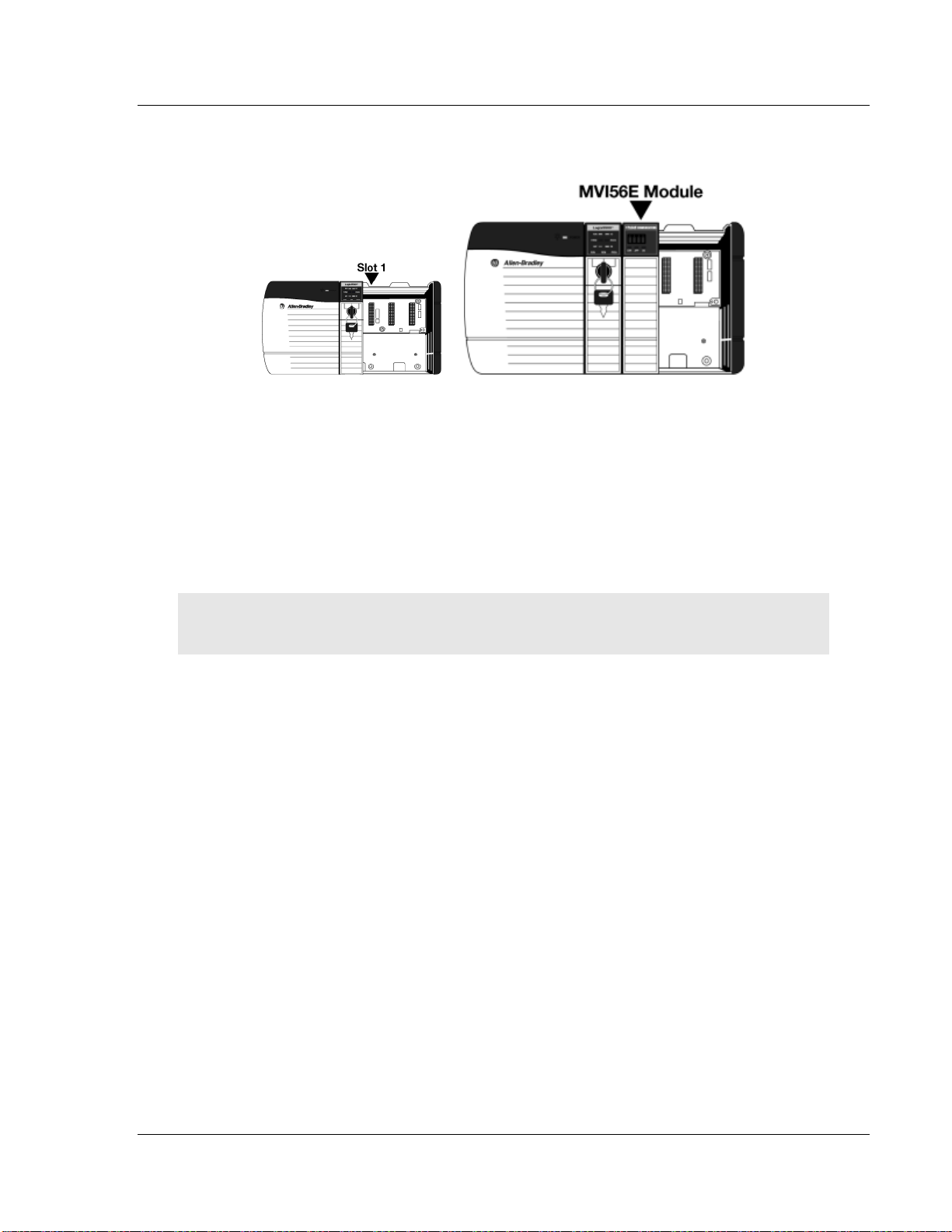
1 Align the module with the top and bottom guides, and then slide it into the
rack until the module is firmly against the backplane connector.
2 With a firm, steady push, snap the module into place.
3 Check that the holding clips on the top and bottom of the module are securely
in the locking holes of the rack.
4 Make a note of the slot location. You must identify the slot in which the
module is installed in order for the sample program to work correctly. Slot
numbers are identified on the green circuit board (backplane) of the
ControlLogix rack.
5 Turn power ON.
Note: If you insert the module improperly, the system may stop working or may behave
unpredictably.
ProSoft Technology, Inc. Page 17 of 223
Page 18

Start Here MVI56E-MCMR ♦ ControlLogix Platform
File Name
Description
MVI56(E)MCMR_AddOn_Rung_<VersionNu
mPri>.L5X
L5X file containing Add-On Instruction, user defined
data types, controller tags and ladder logic required
to configure the MVI56E-MCMR module
MVI56(E)MCMR_Optional_AddOn_Rung_vX
XX.L5X
Optional L5X file containing additional Add-On
Instruction with logic for changing Ethernet
configuration and clock settings.
User Manual Modbus Communication Module with Reduced Data Block
1.7 Importing the Sample Add-On Instruction
Note: This section only applies if your processor is using RSLogix 5000 version 16 or higher. If you
have an earlier version, please see Using the Sample Program (page 201).
Before You Begin
Two Add-On Instructions are provided for the MVI56E-MCMR module. The first is
required for setting up the module; the second is optional.
Copy the files from www.prosoft-technology.com. Save them to a convenient
location in your PC, such as Desktop or My Documents.
1.7.1 About the Optional Add-On Instruction
The Optional Add-On Instruction performs the following tasks:
Read/Write Ethernet Configuration
Allows the processor to read or write the module IP address, subnet mask,
and network gateway IP address.
Read/Write Module Clock Value
Allows the processor to read and write the module clock settings. The
module's free-running clock also stores the last time that the Ethernet
configuration was changed or the last time the module was restarted or
rebooted. The date and time of the last change or restart is displayed on the
scrolling LED during module power-up/start-up sequence.
Note: You can also set the date and time from the module's home page (page 127).
Important: The Optional Add-On Instruction supports only the two features listed above. You must
use the regular MVI56E-MCMR Add-On Instruction for all other features including backplane
transfer and Modbus data communication.
Page 18 of 223 ProSoft Technology, Inc.
Page 19
MVI56E-MCMR ♦ ControlLogix Platform Start Here
Modbus Communication Module with Reduced Data Block User Manual
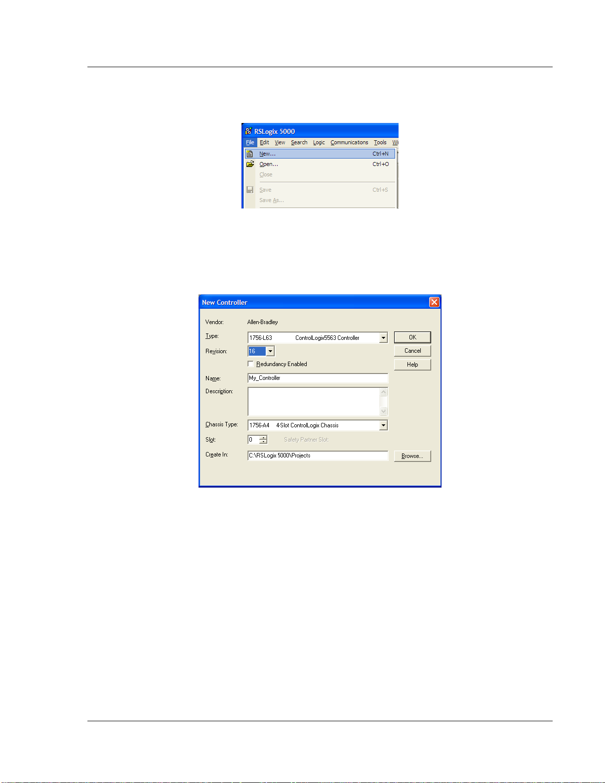
1.8 Creating a New RSLogix 5000 Project
1 Open the FILE menu, and then choose NEW.
2 Select your ControlLogix controller model.
3 Select the REVISION of the controller.
4 Enter a name for your controller, such as My_Controller.
5 Select your ControlLogix chassis type.
6 Select SLOT 0 for the controller.
ProSoft Technology, Inc. Page 19 of 223
Page 20
Start Here MVI56E-MCMR ♦ ControlLogix Platform
User Manual Modbus Communication Module with Reduced Data Block
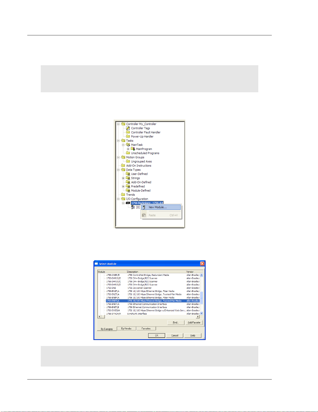
1.8.1 Creating the Remote Network
Note: If you are installing the MVI56E-MCMR module in a remote rack, follow these steps. If you
are installing the module in a local rack, follow the steps in Creating the Module - Local Rack (page
25).
1 Right-click I/O CONFIGURATION and choose NEW MODULE.
2 Expand the Communications module selections and then select the Ethernet
Bridge module that matches your hardware. This example uses a 1756ENBT/A module.
Note: If you are prompted to Select Major Revision, choose the lower of the available revision
numbers.
Page 20 of 223 ProSoft Technology, Inc.
Page 21

MVI56E-MCMR ♦ ControlLogix Platform Start Here
Modbus Communication Module with Reduced Data Block User Manual
3 Name the ENBT/A module, then set the IP Address and Slot location in the
local rack with the ControlLogix processor.
4 Click OK.
5 Next, select the 1756-ENBT module that you just created in the Controller
Organization pane and click the right mouse button to open a shortcut menu.
On the shortcut menu, choose NEW MODULE.
6 Repeat steps 2 and 3 to add the second EtherNet/IP module to the remote
rack.
ProSoft Technology, Inc. Page 21 of 223
Page 22
Start Here MVI56E-MCMR ♦ ControlLogix Platform
User Manual Modbus Communication Module with Reduced Data Block
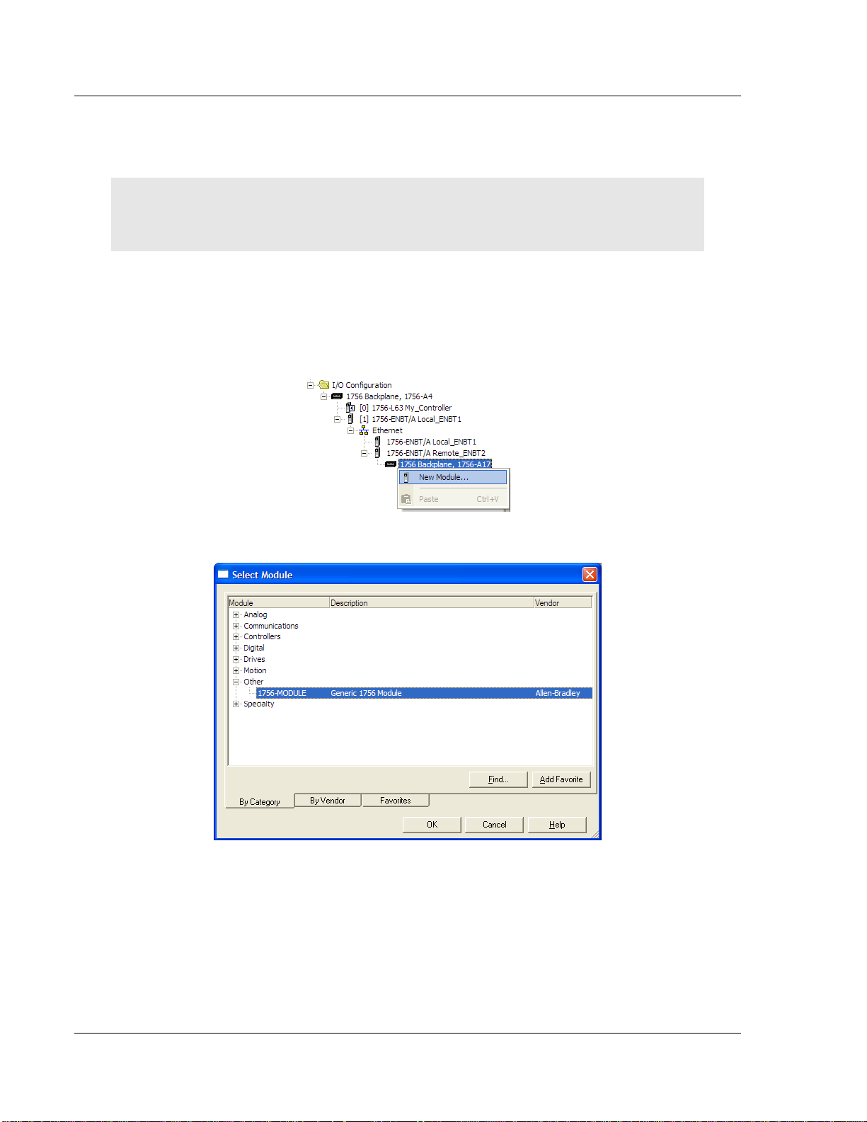
1.8.2 Creating the Module in a Remote Rack
Note: To continue installing the MVI56E-MCMR module in a remote rack, follow these steps. If you
are installing the module in a local rack, follow the steps in Creating the Module - Local Rack (page
25).
1 Select the remote 1756 BACKPLANE node in the Controller Organization pane
underneath the remote rack EtherNet/IP module you just created and click
the right mouse button to open a shortcut menu. On the shortcut menu,
choose NEW MODULE.
This action opens the SELECT MODULE dialog box.
Page 22 of 223 ProSoft Technology, Inc.
Page 23
MVI56E-MCMR ♦ ControlLogix Platform Start Here
Parameter
Value
Name
Enter a module identification string. The recommended value is
MCMR, as this name will be linked automatically with the MSG
paths, irrespective of the slot location.
Description
Enter a description for the module. Example: ProSoft
communication module for Modbus Serial protocol
communications.
Comm Format
Select DATA-INT (*Very Important*)
Slot
Enter the slot number in the rack where the MVI56E-MCMR
module is to be installed.
Input Assembly Instance
1
Input Size
42
Output Assembly Instance
2
Output Size
42
Configuration Assembly Instance
4
Configuration Size
0
Modbus Communication Module with Reduced Data Block User Manual
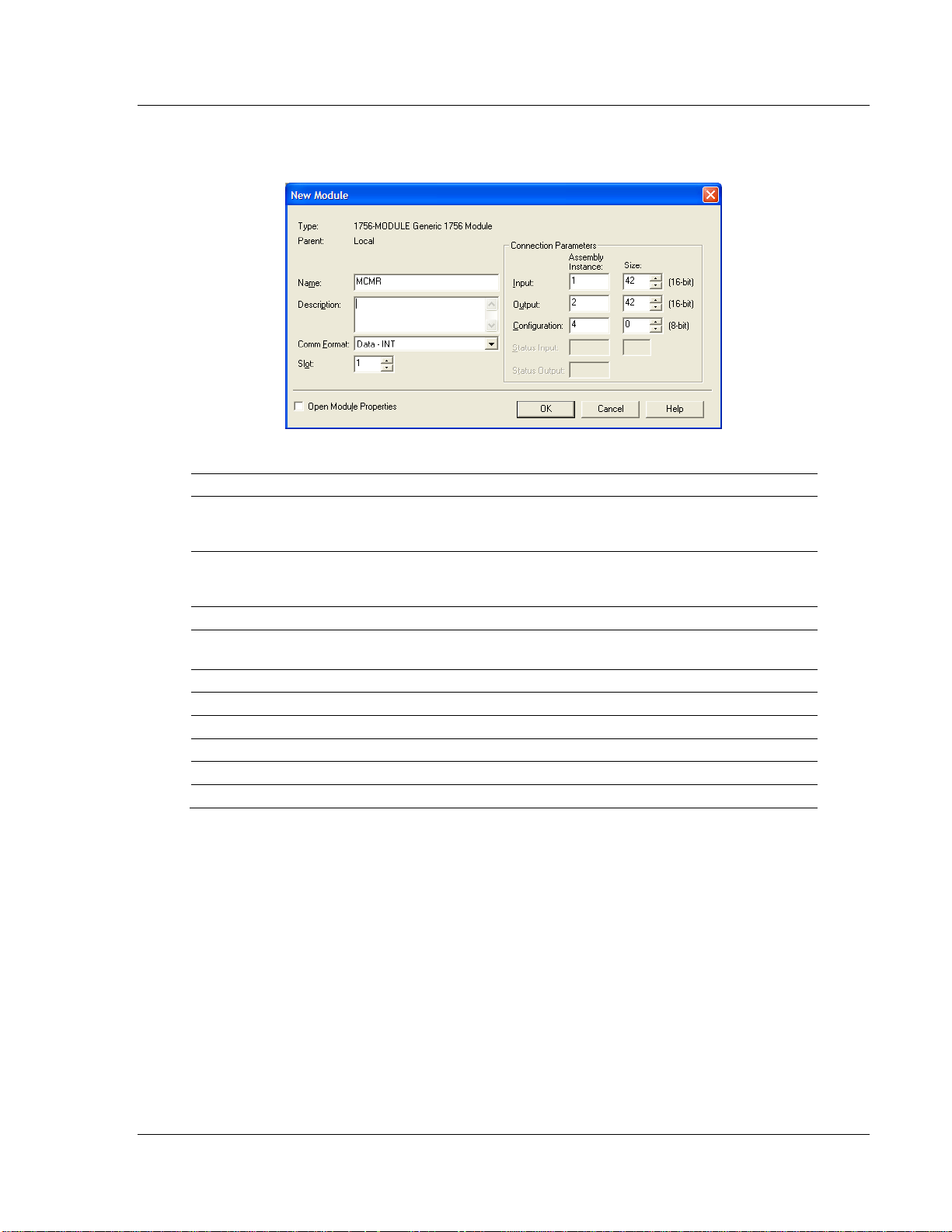
2 Select the 1756-MODULE (GENERIC 1756 MODULE) from the list and click OK.
This action opens the NEW MODULE dialog box.
3 Set the Module Properties values as follows:
ProSoft Technology, Inc. Page 23 of 223
Page 24
Start Here MVI56E-MCMR ♦ ControlLogix Platform
User Manual Modbus Communication Module with Reduced Data Block
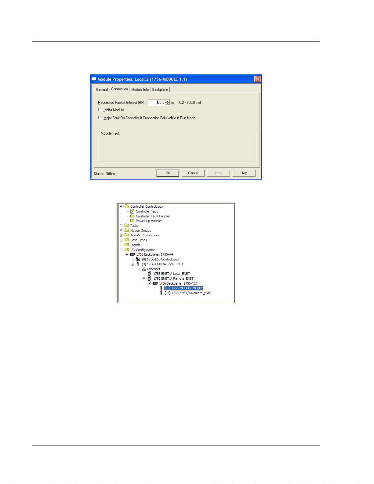
4 On the CONNECTION tab, set the RPI value for your project. Fifty (50)
milliseconds is usually a good starting value.
The MVI56E-MCMR module is now visible in the I/O CONFIGURATION section
Page 24 of 223 ProSoft Technology, Inc.
Page 25
MVI56E-MCMR ♦ ControlLogix Platform Start Here
Modbus Communication Module with Reduced Data Block User Manual
1.8.3 Creating the Module in a Local Rack
Note: If you are installing the MVI56E-MCMR module in a local rack, follow these steps. If you are
installing the module in a remote rack, follow the steps in Creating the Module - Remote Rack
(page 20).
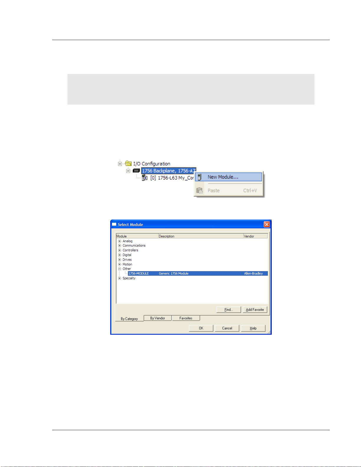
1 Add the MVI56E-MCMR module to the project.
In the CONTROLLER ORGANIZATION window, select I/O CONFIGURATION and
click the right mouse button to open a shortcut menu. On the shortcut menu,
choose NEW MODULE...
This action opens the SELECT MODULE dialog box.
ProSoft Technology, Inc. Page 25 of 223
Page 26

Start Here MVI56E-MCMR ♦ ControlLogix Platform
Parameter
Value
Name
Enter a module identification string. The recommended value is
MCMR, as this name will be linked automatically with the MSG
paths, irrespective of the slot location.
Description
Enter a description for the module. Example: ProSoft
communication module for Modbus Serial protocol
communications.
Comm Format
Select DATA-INT (*Very Important*)
Slot
Enter the slot number in the rack where the MVI56E-MCMR
module is to be installed.
Input Assembly Instance
1
Input Size
42
Output Assembly Instance
2
Output Size
42
Configuration Assembly Instance
4
Configuration Size
0
User Manual Modbus Communication Module with Reduced Data Block
2 Select the 1756-MODULE (GENERIC 1756 MODULE) from the list and click OK.
This action opens the NEW MODULE dialog box.
3 Set the Module Properties values as follows:
Page 26 of 223 ProSoft Technology, Inc.
Page 27

MVI56E-MCMR ♦ ControlLogix Platform Start Here
Modbus Communication Module with Reduced Data Block User Manual
4 On the CONNECTION tab, set the RPI value for your project. Five (5)
milliseconds is usually a good starting value. Click OK to confirm.
The MVI56E-MCMR module is now visible in the I/O CONFIGURATION section
ProSoft Technology, Inc. Page 27 of 223
Page 28
Start Here MVI56E-MCMR ♦ ControlLogix Platform
User Manual Modbus Communication Module with Reduced Data Block
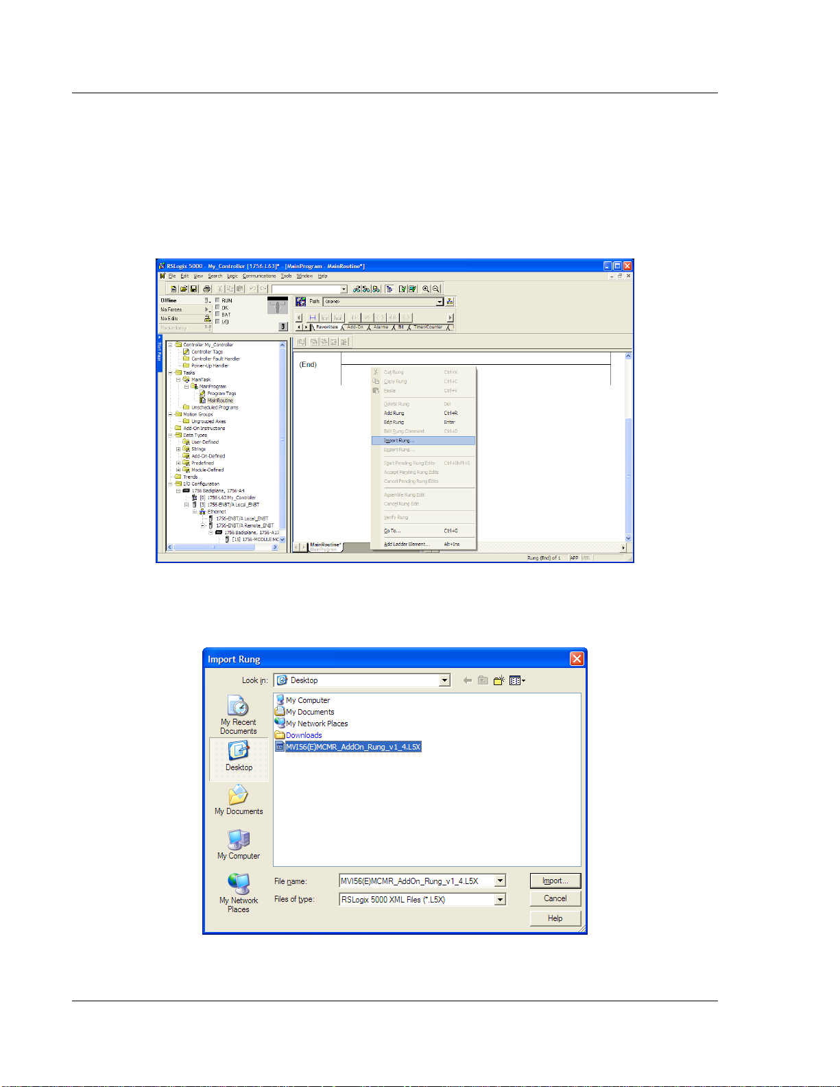
1.8.4 Importing the Ladder Rung
1 In the CONTROLLER ORGANIZATION window, expand the TASKS folder and
subfolder until you reach the MAINPROGRAM folder.
2 In the MAINPROGRAM folder, double-click to open the MAINROUTINE ladder.
3 Select an empty rung in the new routine, and then click the right mouse
button to open a shortcut menu. On the shortcut menu, choose IMPORT
RUNG…
4 Navigate to the location on your PC where you saved (page 18) the Add-On
Instruction (for example, "My Documents" or "Desktop"). Select the
MVI56(E)MCMR_ADDON_RUNG_V1_X.L5X file
Page 28 of 223 ProSoft Technology, Inc.
Page 29
MVI56E-MCMR ♦ ControlLogix Platform Start Here
Modbus Communication Module with Reduced Data Block User Manual
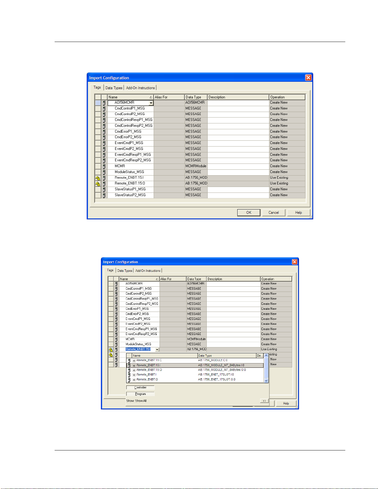
This action opens the IMPORT CONFIGURATION dialog box, showing the
controller tags that will be created.
5 Locate the Remote_ENBT:x:I Tag, where x is the slot number of the module
within the local rack. Rename this tag to: Local:x:I. Do the same for
Local:x:O. This defines the backplane path to the module in a local rack.
ProSoft Technology, Inc. Page 29 of 223
Page 30

Start Here MVI56E-MCMR ♦ ControlLogix Platform
User Manual Modbus Communication Module with Reduced Data Block
6 Click OK to confirm the import. RSLogix will indicate that the import is in
progress:
When the import is completed, the new rung with the Add-On Instruction will
be visible as shown in the following illustration.
The procedure has also imported new User Defined Data Types, Controller
Tags, and the Add-On instruction for your project.
7 Save the application and then download the sample ladder logic into the
processor.
Page 30 of 223 ProSoft Technology, Inc.
Page 31

MVI56E-MCMR ♦ ControlLogix Platform Start Here
Parameter
Value
Name
Enter a module identification string. The recommended value is
MCMR_2. You will need to link this name with the MSG paths for
the AOI.
Description
Enter a description for the module. Example: Modbus
Communication Module with Reduced Data Block
Comm Format
Select DATA-INT (Very Important)
Slot
Enter the slot number in the rack where the MVI56E-MCMR
module is located.
Input Assembly Instance
1
Input Size
42
Output Assembly Instance
2
Output Size
42
Configuration Assembly
Instance
4
Configuration Size
0
Modbus Communication Module with Reduced Data Block User Manual
Adding Multiple Modules (Optional)
Important: If your application requires more than one MVI56E-MCMR module in the same project,
follow the steps below.
1 In the I/O CONFIGURATION folder, click the right mouse button to open a
shortcut menu, and then choose NEW MODULE.
2 Select 1756-MODULE
3 Fill the module properties as follows:
ProSoft Technology, Inc. Page 31 of 223
Page 32

Start Here MVI56E-MCMR ♦ ControlLogix Platform
User Manual Modbus Communication Module with Reduced Data Block
4 Click OK to confirm. The new module is now visible:
5 Expand the TASKS folder, and then expand the MAINTASK folder.
6 On the MAINPROGRAM folder, click the right mouse button to open a shortcut
menu. On the shortcut menu, choose NEW ROUTINE. As an alternative to
creating a separate New Routine, you could skip to Step 8 and import the
AOI for the second module into the same routine you created for the first
module.
7 In the NEW ROUTINE dialog box, enter the name and description of your
routine, and then click OK.
8 Select an empty rung in the new routine or an existing routine, and then click
the right mouse button to open a shortcut menu. On the shortcut menu,
choose IMPORT RUNG…
Page 32 of 223 ProSoft Technology, Inc.
Page 33

MVI56E-MCMR ♦ ControlLogix Platform Start Here
Modbus Communication Module with Reduced Data Block User Manual
9 Select the MVI56(E)MCMR_ADDON_RUNG_V1_4.L5X file, and then click
IMPORT.
10 This action opens the IMPORT CONFIGURATION window, which shows the tags
that will be imported.
ProSoft Technology, Inc. Page 33 of 223
Page 34

Start Here MVI56E-MCMR ♦ ControlLogix Platform
User Manual Modbus Communication Module with Reduced Data Block
11 Associate the I/O connection variables to the correct module. The default
values are Remote_ENBT:15:I and Remote_ENBT:15:I so these require
change.
Page 34 of 223 ProSoft Technology, Inc.
Page 35

MVI56E-MCMR ♦ ControlLogix Platform Start Here
Modbus Communication Module with Reduced Data Block User Manual
12 Change the default tags MCMR and AOI56MCMR to avoid conflict with
existing tags. In this procedure, you will append the string "_2" to all tags to
be imported as shown in the following illustration.
13 Click OK to confirm.
ProSoft Technology, Inc. Page 35 of 223
Page 36

Start Here MVI56E-MCMR ♦ ControlLogix Platform
User Manual Modbus Communication Module with Reduced Data Block
Configuring the Path for Message Blocks
If you used the recommended name for the module (MCMR) to import the first
Add-On Instruction, the MSG paths will be associated correctly with the module.
For additional modules, you must configure the message path for each MSG
instruction to address the correct module.
1 In the Add-On Instruction, click the [...] button next to each MSG tag to open
the MESSAGE CONFIGURATION TAG.
2 Click the COMMUNICATION tab and click the BROWSE button as follows.
Page 36 of 223 ProSoft Technology, Inc.
Page 37

MVI56E-MCMR ♦ ControlLogix Platform Start Here
Modbus Communication Module with Reduced Data Block User Manual
3 Select the module to configure the message path.
4 Repeat these steps for each MSG tag, and for each additional MVI56E-
MCMR module.
The setup procedure is now complete. Save the project and download the
application to your ControlLogix processor.
1.8.5 Adjusting the Input and Output Array Sizes
The module internal database is divided into two user-configurable areas:
Read Data
Write Data
The Read Data area is moved from the module to the processor, while the Write
Data area is moved from the processor to the module. You can configure the
start register and size of each area. The size of each area you configure must
match the Add-On instruction controller tag array sizes for the READDATA and
WRITEDATA arrays.
The MVI56E-MCMR sample program is configured for 600 registers of
READDATA and 600 registers of WRITEDATA, which is sufficient for most
applications. This topic describes how to configure user data for applications
requiring more than 600 registers of ReadData and WriteData.
Important: Because the module pages data in blocks of 40 registers at a time, you must configure
your user data in multiples of 40 registers.
Caution: When you change the array size, RSLogix may reset the MCMR tag values to zero. To
avoid data loss, be sure to save your settings before continuing.
ProSoft Technology, Inc. Page 37 of 223
Page 38

Start Here MVI56E-MCMR ♦ ControlLogix Platform
User Manual Modbus Communication Module with Reduced Data Block
1 In the CONTROLLER ORGANIZATION window, expand the DATA TYPES and
USER-DEFINED folders, and then double-click MCMRDATA. This action opens
an edit window for the MCMRDATA data type.
2 In the edit window, change the value of the READDATA array from INT[600] to
INT[1000] as shown, and then click APPLY.
Note: If RSLogix resets your data values, refer to the backup copy of your program to re-enter your
configuration parameters.
Important: When you change the ReadData and WriteData array sizes in RSLogix, you must also
change the Read Register Count and Write Register Count values in ProSoft Configuration Builder
(page 53).
3 In ProSoft Configuration Builder, navigate to the BACKPLANE CONFIGURATION
tag (page 53), and double click to open an edit window. Change the READ
REGISTER COUNT value to match the value you entered in RSLogix for the
ReadData data type.
Page 38 of 223 ProSoft Technology, Inc.
Page 39

MVI56E-MCMR ♦ ControlLogix Platform Start Here
Modbus Communication Module with Reduced Data Block User Manual
4 Save and download the sample program to the processor.
To modify the WRITEDATA array, follow the steps in this topic, but substitute
WRITEDATA for ReadData throughout. Also, make sure that the READDATA and
WRITEDATA arrays do not overlap in the module memory. For example, if your
application requires 2000 words of WriteData starting at register 0, then your
READ REGISTER START parameter must be set to a value of 2000 or greater in
ProSoft Configuration Builder.
ProSoft Technology, Inc. Page 39 of 223
Page 40

Start Here MVI56E-MCMR ♦ ControlLogix Platform
User Manual Modbus Communication Module with Reduced Data Block
1.9 Connecting Your PC to the ControlLogix Processor
There are several ways to establish communication between your PC and the
ControlLogix processor. The following steps show how to establish
communication through the serial interface. It is not mandatory that you use the
processor's serial interface. You may access the processor through whatever
network interface is available on your system. Refer to your Rockwell Automation
documentation for information on other connection methods.
1 Connect the right-angle connector end of the cable to your controller at the
communications port.
2 Connect the straight connector end of the cable to the serial port on your
computer.
Page 40 of 223 ProSoft Technology, Inc.
Page 41

MVI56E-MCMR ♦ ControlLogix Platform Start Here
Modbus Communication Module with Reduced Data Block User Manual
1.10 Downloading the Sample Program to the Processor
Note: The key switch on the front of the ControlLogix processor must be in the REM or PROG
position.
1 If you are not already online with the processor, open the Communications
menu, and then choose DOWNLOAD. RSLogix 5000 will establish
communication with the processor. You do not have to download through the
processor's serial port, as shown here. You may download through any
available network connection.
2 When communication is established, RSLogix 5000 will open a confirmation
dialog box. Click the DOWNLOAD button to transfer the sample program to the
processor.
3 RSLogix 5000 will compile the program and transfer it to the processor. This
process may take a few minutes.
4 When the download is complete, RSLogix 5000 will open another
confirmation dialog box. If the key switch is in the REM position, click OK to
switch the processor from PROGRAM mode to RUN mode.
Note: If you receive an error message during these steps, refer to your RSLogix documentation to
interpret and correct the error.
ProSoft Technology, Inc. Page 41 of 223
Page 42

Start Here MVI56E-MCMR ♦ ControlLogix Platform
User Manual Modbus Communication Module with Reduced Data Block
1.10.1 Configuring the RSLinx Driver for the PC COM Port
If RSLogix is unable to establish communication with the processor, follow these
steps.
1 Open RSLinx.
2 Open the COMMUNICATIONS menu, and choose CONFIGURE DRIVERS.
This action opens the Configure Drivers dialog box.
Note: If the list of configured drivers is blank, you must first choose and configure a driver from the
Available Driver Types list. The recommended driver type to choose for serial communication with
the processor is RS-232 DF1 Devices.
Page 42 of 223 ProSoft Technology, Inc.
Page 43

MVI56E-MCMR ♦ ControlLogix Platform Start Here
Modbus Communication Module with Reduced Data Block User Manual
3 Click to select the driver, and then click CONFIGURE. This action opens the
Configure RS-232 DF1 Devices dialog box.
4 Click the AUTO-CONFIGURE button. RSLinx will attempt to configure your
serial port to work with the selected driver.
5 When you see the message Auto Configuration Successful, click the OK
button to dismiss the dialog box.
Note: If the auto-configuration procedure fails, verify that the cables are connected correctly
between the processor and the serial port on your computer, and then try again. If you are still
unable to auto-configure the port, refer to your RSLinx documentation for further troubleshooting
steps.
ProSoft Technology, Inc. Page 43 of 223
Page 44

MVI56E-MCMR ♦ ControlLogix Platform
User Manual Modbus Communication Module with Reduced Data Block
Page 44 of 223 ProSoft Technology, Inc.
Page 45

MVI56E-MCMR ♦ ControlLogix Platform Configuring the MVI56E-MCMR Module
In This Chapter
Installing ProSoft Configuration Builder ................................................. 45
Using ProSoft Configuration Builder Software ....................................... 46
Configuration as a Modbus Master ........................................................ 52
Configuration as a Modbus Slave .......................................................... 78
Ethernet Configuration .......................................................................... 87
Connecting Your PC to the Module's Ethernet Port ............................... 88
Downloading the Project to the Module ................................................. 92
Modbus Communication Module with Reduced Data Block User Manual
2 Configuring the MVI56E-MCMR Module
2.1 Installing ProSoft Configuration Builder
The ProSoft Configuration Builder (PCB) software is used to configure the
module. You can find the latest version of the ProSoft Configuration Builder
(PCB) on our web site: http://www.prosoft-technology.com. The installation
filename contains the PCB version number. For example,
PCB_4.1.0.4.0206.EXE.
1 Open a browser window and navigate to
http://www.prosoft-technology.com/pcb.
2 Click the download link for ProSoft Configuration Builder, and save the file to
your Windows desktop.
3 After the download completes, double-click on the PCB installation file, and
follow the instructions that appear on the screen.
4 If you want to find additional software specific to your MVI56E-MCMR, enter
the model number into the website search box and press the Enter key.
ProSoft Technology, Inc. Page 45 of 223
Page 46

Configuring the MVI56E-MCMR Module MVI56E-MCMR ♦ ControlLogix Platform
User Manual Modbus Communication Module with Reduced Data Block
2.2 Using ProSoft Configuration Builder Software
ProSoft Configuration Builder (PCB) provides a quick and easy way to manage
module configuration files customized to meet your application needs. PCB is not
only a powerful solution for new configuration files, but also allows you to import
information from previously installed (known working) configurations to new
projects.
Note: During startup and initialization, the MVI56E-MCMR module receives its protocol and
backplane configuration information from the installed Personality Module (Compact Flash). Use
ProSoft Configuration Builder to configure module settings and to download changes to the
Personality Module.
2.2.1 Upgrading from MVI56-MCMR in ProSoft Configuration Builder
MVI56E-MCMR modules are fully backward-compatible with MVI56-MCMR
modules. However, you will need to convert your MVI56-MCMR configuration in
ProSoft Configuration Builder to a form that your new MVI56E-MCMR module will
accept when you download it.
ProSoft Configuration Builder version 2.2.2 or later has an upgrade option that
easily performs this conversion, while preserving all your configuration settings
and any name you may have given your module.
Important: For this procedure, you need to have ProSoft Configuration Builder version 2.2.2 or
later installed on your PC. You can download the latest version from www.prosoft-technology.com.
Page 46 of 223 ProSoft Technology, Inc.
Page 47

MVI56E-MCMR ♦ ControlLogix Platform Configuring the MVI56E-MCMR Module
Modbus Communication Module with Reduced Data Block User Manual
1 In ProSoft Configuration Builder's tree view, click the MODULE icon and right-
click to open a shortcut menu.
2 On the shortcut menu, select CHANGE MODULE TYPE TO MVI56E-MCMR.
ProSoft Technology, Inc. Page 47 of 223
Page 48

Configuring the MVI56E-MCMR Module MVI56E-MCMR ♦ ControlLogix Platform
User Manual Modbus Communication Module with Reduced Data Block
2.2.2 Setting Up the Project
To begin, start PROSOFT CONFIGURATION BUILDER (PCB).
If you have used other Windows configuration tools before, you will find the
screen layout familiar. PCB’s window consists of a tree view on the left, and an
information pane and a configuration pane on the right side of the window. When
you first start PCB, the tree view consists of folders for Default Project and
Default Location, with a Default Module in the Default Location folder. The
following illustration shows the PCB window with a new project.
Page 48 of 223 ProSoft Technology, Inc.
Page 49

MVI56E-MCMR ♦ ControlLogix Platform Configuring the MVI56E-MCMR Module
Modbus Communication Module with Reduced Data Block User Manual
Your first task is to add the MVI56E-MCMR module to the project.
1 Use the mouse to select DEFAULT MODULE in the tree view, and then click the
right mouse button to open a shortcut menu.
2 On the shortcut menu, select CHOOSE MODULE TYPE. This action opens the
Choose Module Type dialog box.
3 In the Product Line Filter area of the dialog box, select MVI56E. In the Select
Module Type dropdown list, select MVI56E-MCMR, and then click OK to save
your settings and return to the ProSoft Configuration Builder window.
ProSoft Technology, Inc. Page 49 of 223
Page 50

Configuring the MVI56E-MCMR Module MVI56E-MCMR ♦ ControlLogix Platform
User Manual Modbus Communication Module with Reduced Data Block
2.2.3 Setting Module Parameters
Notice that the contents of the information pane and the configuration pane
changed when you added the MVI56E-MCMR module to the project.
At this time, you may wish to rename the Default Project and Default Location
folders in the tree view.
Renaming an Object
1 Select the object, and then click the right mouse button to open a shortcut
menu. From the shortcut menu, choose RENAME.
2 Type the name to assign to the object.
3 Click away from the object to save the new name.
Configuring Module Parameters
1 Click on the [+] sign next to the module icon to expand module information.
2 Click on the [+] sign next to any icon to view module information and
configuration options.
3 Double-click any icon to open an Edit dialog box.
4 To edit a parameter, select the parameter in the left pane and make your
changes in the right pane.
5 Click OK to save your changes.
Page 50 of 223 ProSoft Technology, Inc.
Page 51

MVI56E-MCMR ♦ ControlLogix Platform Configuring the MVI56E-MCMR Module
Modbus Communication Module with Reduced Data Block User Manual
Creating Optional Comment Entries
1 Click the [+] to the left of the icon to expand the module
comments.
2 Double-click the icon. The Edit - Module Comment dialog box
appears.
3 Enter your comment and click OK to save your changes.
Printing a Configuration File
1 Select the module icon, and then click the right mouse button to open a
shortcut menu.
2 On the shortcut menu, choose VIEW CONFIGURATION. This action opens the
View Configuration window.
3 In the View Configuration window, open the FILE menu, and choose PRINT.
This action opens the Print dialog box.
4 In the Print dialog box, choose the printer to use from the drop-down list,
select printing options, and then click OK.
ProSoft Technology, Inc. Page 51 of 223
Page 52

Configuring the MVI56E-MCMR Module MVI56E-MCMR ♦ ControlLogix Platform
User Manual Modbus Communication Module with Reduced Data Block
2.3 Configuration as a Modbus Master
2.3.1 Overview
This section describes how to configure the module as a MODBUS MASTER
device. The Master is the only device on a Modbus network that can initiate
communications. A Master device issues a request message, and then waits for
the slave to respond. When the slave responds, or when a timeout has occurred,
the Modbus Master will then execute the next command in the list.
The following ProSoft Configuration Builder sections contain the Modbus Master
configuration. You must configure all three sections.
1 The BACKPLANE CONFIGURATION section sets up the backplane
communication between the MVI56E-MCMR module and the ControlLogix
processor (page 53). These settings include register addresses for ReadData
and WriteData. You can configure up to 5000 data registers in the module to
exchange data with the ControlLogix processor.
2 The MODBUS PORT1 and MODBUS PORT 2 sections configure the Modbus
application serial ports (page 54). These sections configure parameters such
as baud rate, parity, data bits, stop bits, and command response timeout.
3 The MODBUS PORT 1 COMMANDS and MODBUS PORT 2 COMMANDS sections
define a polling table (command list) for the Modbus Master (page 57). These
sections contain the addresses for devices on the network, the types of data
(Modbus Function Codes) to read from and write to those devices, and the
location to store the data within the module’s 5000 data registers.
Page 52 of 223 ProSoft Technology, Inc.
Page 53

MVI56E-MCMR ♦ ControlLogix Platform Configuring the MVI56E-MCMR Module
Parameter
Description
Error/Status Block Pointer
Used mainly when the module is configured as a Slave. This
parameter places the STATUS data into the database of the module.
Read Register Start
Specifies the starting register in the module's database for sending
data to the ReadData controller tag array in the ControlLogix
processor.
Read Register Count
Sets how many registers of data the MVI56E-MCMR module will
send to the ControlLogix processor's ReadData array. This value is
best if set to a multiple of 200 (40 for MCMR).
Write Register Start
Specifies where in the 5000 register module memory to start placing
data sent from the WriteData tag array in the ControlLogix processor.
Write Register Count
Specifies how many registers of data the MVI56E-MCMR module will
request from the ControlLogix processor. Because the module pages
data in blocks of 40 words, this number is best if it is evenly divisible
by 40.
Backplane Fail Count
Sets the consecutive number of backplane failures that will cause the
module to stop communications on the Modbus network. Typically
used when the module is configured as a Slave.
Modbus Communication Module with Reduced Data Block User Manual
2.3.2 Backplane Configuration
The BACKPLANE CONFIGURATION section defines the 5000 data registers to use
for read and write data within the MVI56E-MCMR module. You will use these
data read and write locations in the Internal Address tag within each Master
Command (page 57). The following illustration shows the values from the sample
program.
The WRITE REGISTER START parameter determines the starting register location
for WRITEDATA[0 to 599]. The WRITE REGISTER COUNT determines how many of
the 5000 registers to use send data to the module. The sample ladder file uses
600 registers for write data, labeled MCMR.DATA.WRITEDATA[0 to 599].
ProSoft Technology, Inc. Page 53 of 223
Page 54

Configuring the MVI56E-MCMR Module MVI56E-MCMR ♦ ControlLogix Platform
User Manual Modbus Communication Module with Reduced Data Block
The sample configuration values configure the module database to store
WRITEDATA[0 to 599] in registers 0 to 599, and READDATA[0 TO 599] in registers
1000 to 1599, as shown in the following illustration.
Important: If you need to configure different values for the Read Register Count and Write
Register Count parameters, you must also configure the same values in the user-defined data type
MCMRData in the sample program (page 37).
2.3.3 Port Configuration
The MODBUS PORT X configuration parameters are used when the module is
configured as a Modbus Master device. Port 1 and Port 2 each have their own
set of configuration parameters.
Note: Any changes made within the configuration file must be downloaded to the MVI56E-MCMR
module from ProSoft Configuration Builder.
In ProSoft Configuration Builder, expand the MVI56E-MCMR node, and then
expand the MCM PORT 1 node. Double-click the MODBUS PORT 1 icon. In the
EDIT - MODBUS PORT 1 dialog box, click to highlight the Type parameter, and then
select MASTER from the dropdown list.
Page 54 of 223 ProSoft Technology, Inc.
Page 55

MVI56E-MCMR ♦ ControlLogix Platform Configuring the MVI56E-MCMR Module
Parameter
Description
Enabled
1 = ENABLE PORT, 0 = disable port
Type
0 = MASTER, 1 = Slave
Protocol
0 = MODBUS RTU MODE, 1 = Modbus ASCII mode
Baud Rate
Sets the baud rate for the port. Valid values for this field are 110, 150,
300, 600, 1200, 2400, 4800, 9600, 19200, 384 or 3840 (for 38,400
baud), 576 or 5760 (for 57,600 baud) and 115,1152, or 11520 (for
115,200 baud)
Parity
0 = None, 1 = Odd, 2 = Even
Data Bits
Modbus RTU mode = 8 Modbus ASCII mode = 8 or 7
Stop Bits
Valid values are 1 or 2.
RTS On
0 to 65535 milliseconds to delay after RTS line is asserted on the port
before data message transmission begins. This delay can be used to
allow for radio keying or modem dialing before data transmission
begins.
RTS Off
0 to 65535 milliseconds to delay after data message is complete
before RTS line is dropped on the port.
Use CTS Line
NO or YES
This parameter is used to enable or disable hardware handshaking.
The default setting is NO hardware handshaking, CTS Line not used.
Set to NO if the connected devices do not need hardware
handshaking. Set to YES if the device(s) connected to the port require
hardware handshaking (most modern devices do not). If you set this
parameter to YES, be sure to pay attention to the pinout and wiring
requirements to ensure that the hardware handshaking signal lines are
properly connected; otherwise communication will fail.
Modbus Communication Module with Reduced Data Block User Manual
The following parameters are displayed when the Type parameter is set to
MASTER.
The following table describes the parameters in the EDIT – MODBUS PORT 1
dialog box when the Type parameter is set to MASTER.
ProSoft Technology, Inc. Page 55 of 223
Page 56

Configuring the MVI56E-MCMR Module MVI56E-MCMR ♦ ControlLogix Platform
Parameter
Description
Float Flag
YES or NO
Enables or disables use of floating data type
Float Start
0 to 32767
Register offset in message for floats
Float Offset
0 to 3998
Internal address for floats
Function 99 Offset
1 to 247
Modbus node address for this port on the network
Minimum Command Delay
0-65535 milliseconds
The amount of delay in milliseconds to be inserted after receiving a
Slave response or encountering a response timeout before retrying the
command or sending the next command on the list. Use this
parameter to slow down overall polling speed and spread out
commands on networks with Slaves that require additional gaps
between messages.
Command Error Pointer
Internal DB location to place command error list
Each command will reserve one word for the command error code for
that command. See Verify Communication (page 105). CMDERRPTR
value should be within the range of the READDATA array. See
Backplane Configuration (page 53).
Error Delay Counter
This parameter specifies the number of poll attempts to be skipped
before trying to re-establish communications with a slave that has
failed to respond to a command within the time limit set by the
Response Timeout parameter. After the slave fails to respond, the
master will skip sending commands that should have been sent to the
slave until the number of skipped commands matches the value
entered in this parameter. This creates a sort of slow poll mode for
slaves that are experiencing communication problems.
Response Timeout
0 to 65535 milliseconds response timeout for command before it will
either reissue the command, if RETRYCOUNT > 0.
If the RetryCount =0 or if the designated number of retries have been
accomplished, then the Master will move on to the next command in
the list.
Retry Count
Number of times to retry a failed command request before moving to
the next command on the list.
User Manual Modbus Communication Module with Reduced Data Block
Page 56 of 223 ProSoft Technology, Inc.
Page 57

MVI56E-MCMR ♦ ControlLogix Platform Configuring the MVI56E-MCMR Module
Parameter
Description
Enable
0 = Disabled
Command will not be executed, but can be enabled using the
Command Control option in ladder logic.
1 = Enabled
Command is enabled and will be sent out to the target device.
2 = Conditional Write
Only for Func 5, 15, 6, or 16. Data will be sent to the target device
only when the data to be written has changed in the source registers
of the module’s internal database.
Modbus Communication Module with Reduced Data Block User Manual
2.3.4 Master Command Configuration
This topic describes the communications with the Master port and slave devices
that are connected to that port.
In ProSoft Configuration Builder, expand the MVI56E-MCMR node, and then
double-click the MODBUS PORT 1 COMMANDS icon.
ProSoft Technology, Inc. Page 57 of 223
Page 58

Configuring the MVI56E-MCMR Module MVI56E-MCMR ♦ ControlLogix Platform
Parameter
Description
Internal Address
0 to 4999 for Register-level commands
0 to 65535 for Bit-level commands
Determines the starting address in the module’s 5000-register
database that will be affected by the command. For a Read
command, this will determine where the data will begin to be placed
in the module database after it has been read from a slave. For read
commands, you should configure this value so that the data will be
placed in the range of module memory designated for ReadData, as
defined in the Backplane Configuration section of this configuration
file. For write commands, the INTERNAL ADDRESS determines where to
begin obtaining the data to write to the slave device. This must be a
location that is in the WriteData area of module memory, as defined
in the Backplane Configuration section of this configuration file.
Note: When using a bit-level command, you must define this field at
the bit level. For example, when using a Function Code 1, 2 for a
Read command, you must have a value of 16000 to place the data in
MCM.ReadData[0] (ReadStartRegister = 1000 * 16 bits per register =
16000).
Poll Interval
0 to 65535
The Poll Interval is the number of seconds that the Master will wait
between successive executions of this command. Set to zero (0) for
the fastest possible polling.
This parameter can be used to prioritize and optimize network traffic
by assigning low values to high-priority poll requests and assigning
higher values to less important data poll commands.
Reg Count
1 to 125 words for Function Codes 3, 4, and 16 (Register-level)
1 to 2000 for Function Codes 1, 2, and 15 (Bit-level)
Sets how many continuous words (Function Codes 3, 4, and 16) or
bits (Function Codes 1, 2, and 15) to request from the slave device.
Note: These values are the maximum allowed in the Modbus
protocol. Some devices may support fewer words or bits per
command than these maximum values.
Swap Code
NO CHANGE, SWAP WORDS, SWAP WORDS & BYTES, SWAP BYTES
Typically used when reading floating-point data. Swaps the data read
from the slave device before it is placed into the module memory. For
example, you receive 4 bytes of data from the slave (ABCD).
NO CHANGE = No swapping (ABCD)
SWAP WORDS = Word pairs switched (CDAB)
SWAP WORDS AND BYTES = Bytes and words switched (DCBA)
SWAP BYTES = Bytes swapped (BADC)
Node Address
1 to 247
Modbus Slave Device Address of the device on the network to read
data from, or write data to. Valid addresses are 1 to 247. Address 0 is
reserved for broadcast write commands (will broadcast a Write
command to all devices on the network).
User Manual Modbus Communication Module with Reduced Data Block
Page 58 of 223 ProSoft Technology, Inc.
Page 59

MVI56E-MCMR ♦ ControlLogix Platform Configuring the MVI56E-MCMR Module
Parameter
Description
ModBus Function
1, 2, 3, 4, 5, 6, 15, and 16 (when viewed in the .CFG text file)
The Modbus Function Code determines what kind of command to
send to the slave device. Valid code numbers and descriptions for
this field are as follows:
Note: The Modbus protocol specifies that the valid address range for
each Modbus data type can be x00001 to x65535. Most newer
Modbus devices support this addressing range. However, some older
Modbus devices may only support addresses that range from x0001
to x9999.
FC 1 = Read Coil (0X)
Use this Function Code to read Modbus Coil addresses 000001 to
065535 (or 0x0001 to 0x9999). These are read/write single-bit binary
values. Use Function Code 5 or 15 to write to these Coil addresses.
FC 2 = Read Input (1X)
Use this Function Code to read Modbus Input Status addresses
100001 to 165535 (or 1x0001 to 1x9999). These are read-only singlebit binary values.
FC 3 = Read Holding Registers (4X)
Use this Function Code to read Modbus Holding Register addresses
400001 to 465535 (or 4x0001 to 4x9999). These are read/write 16-bit
word values. Use Function Code 6 or 16 to write to these Holding
Registers.
FC 4 = Read Input Registers (3X)
Use this Function Code to read Modbus Input Register addresses
300001 to 365535 (or 3x0001 to 3x9999). These are read-only 16-bit
word values.
FC 5 = Force Single Coil (0X)
Use this Function Code to write to Modbus Coil addresses. This
command will write to only one coil per command. Use Function
Code 15 to write to multiple coils in the same command.
FC 6 = Preset Single Register (4X)
Use this Function Code to write to Modbus Holding Registers. This
command will write to only one register per command. Use Function
Code 16 to write to multiple registers in the same command.
FC 15 = Force Multiple Coils (0X)
Use this Function Code to write multiple Coil values with one
command.
FC 16 = Preset Multiple Registers (4X)
Use this Function Code to write multiple Holding Register values with
one command.
Modbus Communication Module with Reduced Data Block User Manual
ProSoft Technology, Inc. Page 59 of 223
Page 60

Configuring the MVI56E-MCMR Module MVI56E-MCMR ♦ ControlLogix Platform
Parameter
Description
MB Address in Device
Specifies the starting Modbus bit or register address where data will
begin being read from or written to the slave device. With Modbus, to
read an address of 40001, what will actually be transmitted out port is
Function Code 03 (one byte) with an address of 00 00 (two bytes).
This means that to read an address of 40501, use FC 3 with a MB
Address in Device of 500.
This applies to all Modbus addresses. Below are some examples that
will help with your MB ADDRESS IN DEVICE configuration:
Function Codes 1, 5, or 15 for reading or writing Modbus Coils
MB Address in Device setting = Modbus Coil address in the Slave
device – 0001
For Modbus Coil address 0001: MB Address in Device = 0
For Modbus Coil address 1378: MB Address in Device = 1377
Function Code 2
MB Address in Device setting = Modbus Input Status address in the
Slave device - 10001
For Modbus address 10001: MB Address in Device = 0
For Modbus Input Status address 10345: MB Address in Device =
344
Function Codes 3, 6, or 16
MB Address in Device setting = Modbus Holding Register address in
the Slave device – 40001
For Modbus Holding Register address 40001; MB Address in Device
= 0
For Modbus Holding Register address 40591; MB Address in Device
= 590
Function Code 4
MB Address in Device setting = Modbus Input Register address in the
Slave device – 30001
For Modbus Input Register address 30001: MB Address in Device = 0
For Modbus Input Register address 34290; MB Address in Device =
4289
User Manual Modbus Communication Module with Reduced Data Block
Page 60 of 223 ProSoft Technology, Inc.
Page 61

MVI56E-MCMR ♦ ControlLogix Platform Configuring the MVI56E-MCMR Module
STATUS
0200
Switch Input Status
0201
LED Status Flags
0202
LED Attribute Flags
0203
Output Relay Status Flags
Modbus Communication Module with Reduced Data Block User Manual
2.3.5 Other Modbus Addressing Schemes
While the above information will handle most devices, some device
manufacturers show their Modbus addressing differently.
The two most common schemes are six-digit addressing (400101, 301000, and
so on) and some devices show their addressing already as an offset address (the
address that actually goes out on the Modbus communication line). When
addresses are given as actual offset addresses, they are usually given as a
hexadecimal (base 16) number. This is an example.
Actual Values (Input Registers) Addresses: 0200 to 0E1F
If your device manufacturer gives you addressing like this "Input Registers"
example above, then you will use Function Code 4 to convert the hexadecimal
value to a decimal equivalent value, and place the decimal value in the MB
ADDRESS IN DEVICE field. So for this example device, use Modbus Function = 4
(Input Registers) with a MB ADDRESS IN DEVICE of 512 decimal (200h) to read the
"Switch Input Status" value.
What if my slave shows addresses such as 400,001 or 301,345?
For 6-digit addressing, use the same function codes and configuration as shown
above, but subtract higher values; 100001 instead of 10001; 300001 instead of
30001; and 400001 instead of 40001.
Function Codes 1, 5, or 15 MB Address in Device = Modbus Coil address in
slave device - 000001
For Modbus Coil address 000001; MB Address in Device = 0
For Modbus Coil address 001378; MB Address in Device = 1377
Function Code 2 MB Address in Device = Modbus Input Status address in slave
device - 100001
For Modbus Input Status address 100001; MB Address in Device = 0
For Modbus Input Status address 100345; MB Address in Device = 344
Function Codes 3, 6, or 16 MB Address in Device = Modbus Holding Register
address in slave device - 400001
For Modbus Holding Register address 400001; MB Address in Device = 0
For Modbus Holding Register address 400591; MB Address in Device = 590
Function Code 4 MB Address in Device = Modbus Input Register address in
device - 300001
For Modbus Input Register address 300001; MB Address in Device = 0
For Modbus Input Register address 304290; MB Address in Device = 4289
For example:
ProSoft Technology, Inc. Page 61 of 223
Page 62

Configuring the MVI56E-MCMR Module MVI56E-MCMR ♦ ControlLogix Platform
User Manual Modbus Communication Module with Reduced Data Block
If our device listed above shows its addressing as follows:
Then: To read "Switch_Input_Status", you would use Function Code 4 and
use a MB Address in Device of 512.
2.3.6 Master Command Examples
Read Holding Registers 4x (Modbus Function Code 3)
The 4x Holding Registers are used for storing analog values such as pressure,
temperature, current, program counters, timer accumulators and presets, and so
on. Holding Registers store values in 16-bit memory registers. These 16-bit
values can be interpreted in different ways that allow Holding Registers to hold
many different data types, such as 8-bit, 16-bit, 32-bit, or 64-bit signed or
unsigned integers, as well as 32-bit or 64-bit floating-point data (page 71) and
other data types.
The following illustration shows the correct parameter values to create a
command to read Modbus addresses 40001 to 40010 from Modbus Slave Device
Address 1.
Page 62 of 223 ProSoft Technology, Inc.
Page 63

MVI56E-MCMR ♦ ControlLogix Platform Configuring the MVI56E-MCMR Module
Parameter
Description
Enable = YES
The module will send the command every time it goes through the
command list.
Internal Address = 1000
Begins placing the data read from the slave device into the module at
address 1000. Internal Address 1000 of the module memory will be
copied into the tag MCMR.DATA.READDATA[0], assuming
MCMR.CONFIG.ReadStartReg = 1000.
Reg Count = 10
Read 10 consecutive registers from the Slave device.
Node Address = 1
Issues the Modbus command to Modbus Slave Device Address 1.
Modbus Function =3
Issues Modbus Function Code 3 to Read Holding Registers.
MB Address in Device = 0
Using Function Code 3, MB Address in Device of 0 will read Holding
Register address 40001 (or 400001, if using 6-digit addressing)
With a count of 10, this command reads 40001 to 40010 (400001 to
400010).
Modbus Communication Module with Reduced Data Block User Manual
Read Input Registers 3xxxxx (Modbus Function Code 4)
Like the 4x holding registers, 3x input registers are used for reading analog
values that are 16-bit register values. You can also use these registers to store
floating-point data (page 71). Unlike the 4x registers, 3x registers are Read Only.
The following illustration shows a sample command to read Modbus addresses
30021 to 30030 of Modbus Slave Device Address 1.
ProSoft Technology, Inc. Page 63 of 223
Page 64

Configuring the MVI56E-MCMR Module MVI56E-MCMR ♦ ControlLogix Platform
Parameter
Description
Enable = 1
The module will send the command every time it goes through the
command list.
Internal Address = 1010
Places the data read from the slave device into the module at
address 1010. Internal Address 1010 of the module memory will be
copied into the tag MCMR.DATA.READDATA[10].
Reg Count = 10
Reads 10 consecutive registers from the slave device.
Node Address = 1
Issues the Modbus command to Modbus Slave Device Address 1.
Modbus Function =4
Issues Modbus Function Code 4 to Read Input Registers.
MB Address in Device =20
Function Code 4 MB Address in Device of 20 will read address 30021
Along with a count of 10, this command reads 30021 to 30030.
User Manual Modbus Communication Module with Reduced Data Block
Page 64 of 223 ProSoft Technology, Inc.
Page 65

MVI56E-MCMR ♦ ControlLogix Platform Configuring the MVI56E-MCMR Module
Parameter
Description
Enable = 1
The module will send the command every time it goes through the
command list.
Internal Address = 16320
Places the data read from the slave device into the module at
address 16320. Internal Address 16320 of the module memory will be
copied into the tag MCMR.DATA.READDATA[20] because 16320
represents a bit address within the memory of the MVI56E-MCMR
module (16320 / 16 = register 1020).
Reg Count = 160
Reads 160 consecutive bits from the Slave device.
Node Address = 1
Issues the Modbus command to Modbus Slave Device Address 1.
Modbus Function =1
Issues Modbus Function Code 1 to Read Coils.
MB Address in Device =
320
Function Code 1, MB Address in Device of 320 will read address
0321
Along with a count of 160, this command reads 0321 to 0480.
Modbus Communication Module with Reduced Data Block User Manual
Read Coil Status 0x (Modbus Function Code 1)
Modbus Function Code 1 reads the Coils addressed at 0001 to 9999 from a
slave device. These are bit values that are read using Modbus Function Code 1,
and can be written to using Function Code 5 or 15. Within a Slave device, this is
an individual bit value. Thus, the Internal Address field must be defined down to
the bit level within your MasterCmd.
The following illustration shows a sample command to read Modbus addresses
0321 to 0480 from Modbus Slave Device Address 1.
ProSoft Technology, Inc. Page 65 of 223
Page 66

Configuring the MVI56E-MCMR Module MVI56E-MCMR ♦ ControlLogix Platform
Parameter
Description
Enable = 1
The module will send the command every time it goes through the
command list.
Internal Address = 16480
Places the data read from the slave device into the module at
address 16480. Internal Address 16480 of the module memory will be
copied into the tag MCMR.DATA.READDATA[30] (bit16480 / 16 =
register 1030).
Reg Count = 16
Reads 16 consecutive registers from the slave device.
Node Address = 1
Issues the Modbus command to Modbus Slave Device Address 1.
Modbus Function =2
Issues Modbus Function Code 2 to Read Input Coils.
MB Address in Device = 80
Function Code 2, MB Address in Device of 80 will read address
10081
Along with a count of 16, this command reads 10081 to 10096.
User Manual Modbus Communication Module with Reduced Data Block
Read Input Status 1x (Modbus Function Code 2)
Use this command to read Input Coils from a slave device. These are single bit
addresses within a Modbus slave device. Unlike Coils 0x, the Input Coils are
Read Only values and cannot be written to by a Modbus Master device. Also like
the Coils 0x, the Internal Address field of this command is defined down to the bit
level within the module memory.
The following illustration shows a sample command to read Modbus addresses
10081 to 10090 of Modbus Slave Device Address 1.
Page 66 of 223 ProSoft Technology, Inc.
Page 67

MVI56E-MCMR ♦ ControlLogix Platform Configuring the MVI56E-MCMR Module
Parameter
Description
Enable = 2
The module will send the command only when the data within the
Internal Address field of the module has changed.
Internal Address = 160
Will write the data to the slave device when the value at
WriteData[10].0 has changed. Because this is a bit-level command,
the Internal Address field must be defined down to the bit level.
Reg Count = 1
Will write a single bit to the device (Function Code 5 will 1 support a
count of 1).
Node Address = 1
Issues the Modbus command to Modbus Slave Device Address 1.
Modbus Function = 5
Issues Modbus Function Code 5 to write a single coil.
MB Address in Device =
512
Function Code 5, MB Address in Device of 512 will read address
0513
Modbus Communication Module with Reduced Data Block User Manual
Preset (Write) Single Coil 0x (Modbus Function Code 5)
Used to write a Coil of a slave device, these are single-bit addresses within a
Modbus slave device. The Internal Address field of this command is defined
down to the bit level within the module memory, and should come from an area
of memory that has been defined within the MCMR.DATA.WRITEDATA area (this
is configured within BACKPLANE CONFIGURATION).
The following illustration shows a sample command to write Modbus addresses
0513 of Modbus Slave Device Address 1, only when the data associated with the
Internal Address has changed.
ProSoft Technology, Inc. Page 67 of 223
Page 68

Configuring the MVI56E-MCMR Module MVI56E-MCMR ♦ ControlLogix Platform
Parameter
Description
Enable = 2
The module will send the command to the slave device only when the
data associated within the Internal Address of the MVI56E-MCMR
module memory has changed.
Internal Address = 320
Writes the data in bit 320 of the module memory to the slave device.
Based on the BACKPLANE CONFIGURATION setting, this would be the
data in MCMR.DATA.WRITEDATA[20].0 to [20].15 in the ladder logic.
Reg Count = 16
Writes 16 consecutive bits to the slave device.
Node Address = 1
Issues the Modbus command to Modbus Slave Device Address 1.
Modbus Function =15
Issues Modbus Function Code 15 to write multiple coils.
MB Address in Device = 0
Function Code 15, MB Address in Device of 0 will read address 0001
Along with a count of 16, this command writes to 0001 to 0016.
User Manual Modbus Communication Module with Reduced Data Block
Write Multiple Coils 0xxx (Modbus Function Code 15)
Use this function code to write multiple Coils in the 0x address range. This
function code sets multiple Coils within a slave device using the same Modbus
command. Not all devices support this function code. Refer to your slave device
documentation before implementing this function code.
This function code will also support the Enable code of 2, to write the data to the
slave device only when the data associated within the Internal Address field of
the module has changed. The Internal Address is once again defined down to the
bit level as a Function Code 15 is a bit level Modbus function.
The following illustration shows a sample command to write Modbus addresses
0001 to 0016 of Modbus Slave Device Address 1.
Page 68 of 223 ProSoft Technology, Inc.
Page 69

MVI56E-MCMR ♦ ControlLogix Platform Configuring the MVI56E-MCMR Module
Parameter
Description
Enable = 1
The module will send the command every time it goes through the
command list.
Internal Address = 5
Writes the data from address 5 of the module memory to the slave
device. Based on the BACKPLANE CONFIGURATION, this will take the
data from MCMR.DATA.WRITEDATA[5] and write that information out
to the slave device.
Reg Count = 1
Writes 1 register (16-bit) to the slave device.
Node Address = 1
Issues the Modbus command to Modbus Slave Device Address 1.
Modbus Function =2
Issues Modbus Function Code 6 to write a single register.
MB Address in Device =
1040
Function Code 6, MB Address in Device of 1040 will write to address
41041 of the Modbus slave device.
Modbus Communication Module with Reduced Data Block User Manual
Preset (Write) Single Register 4x (Modbus Function Code 6)
Used to write to Modbus Holding Registers 4x, this function code will write a
single register to the slave device. The Enable code can be set to a value of 1 for
a continuous write, or a value of 2 to write the data to the slave device only when
the data associated with the Internal Address field has changed.
The following illustration shows a sample command to write Modbus addresses
41041 of Modbus Slave Device Address 1.
ProSoft Technology, Inc. Page 69 of 223
Page 70

Configuring the MVI56E-MCMR Module MVI56E-MCMR ♦ ControlLogix Platform
Parameter
Description
Enable = 2
The module will send the command only when the data associated
with the Internal Address of the module has changed.
Internal Address =30
Writes the data from Internal Address 30 of the module memory to
the Slave device. Based on the BACKPLANE CONFIGURATION, this will
write the data from MCMR.DATA.WRITEDATA[30] TO [39] to the Slave
device.
Reg Count = 10
Writes 10 consecutive registers to the slave device.
Node Address = 1
Issues the Modbus command to Modbus Slave Device Address 1.
Modbus Function =16
Issues Modbus Function Code 16 to write Holding Registers.
MB Address in Device =
1050
Function Code 16, MB Address in Device of 1050 will write address
41051.
Along with a count of 10, this command writes 41051 to 41060 of the
slave device.
User Manual Modbus Communication Module with Reduced Data Block
Preset (Write) Multiple Registers 4x (Modbus Function Code 16)
Used to write to Modbus Holding Registers 4x, this function code will write
multiple registers to the slave device. The Enable code can be set to a value of 1
for a continuous write, or a value of 2 to write the data to the slave device only
when the data associated with the Internal Address field has changed.
The following illustration shows a sample command to write Modbus addresses
41051 to 41060 of Modbus Slave Device Address 1.
Page 70 of 223 ProSoft Technology, Inc.
Page 71

MVI56E-MCMR ♦ ControlLogix Platform Configuring the MVI56E-MCMR Module
Value
Description
Type
40257
--------
KWH
Energy Consumption
Float, lower 16 bits
40258
KWH
Energy Consumption
Float, upper 16 bits
Parameter
Description
Enable = 1
Sends the command every time through the command list.
Internal Address = 1000
Places data at address 1000 of the module memory. Based on the
configuration in ModDef this will put the data at the tag
MCMR.DATA.READDATA[0].
Poll Interval = 0
No delay for this command.
Count = 2
Reads 2 consecutive registers from the Slave device. These 2
Modbus registers will make up the "Energy Consumption" floatingpoint value.
Swap = 0
Swap Code
Description
0
None - No Change is made in the byte ordering
(1234 = 1234)
1
Words - The words are swapped (1234 = 3412)
2
Words & Bytes - The words are swapped then the
bytes in each word are swapped (1234 = 4321)
3
Bytes - The bytes in each word are swapped
(1234 = 2143)
Node = 1
Sends the command to Modbus Slave Device Address 1.
Func = 3
Issues a Modbus Function Code 3 to "Read Holding registers."
MB Address in Device =
256
Along with the Function Code 3, MB Address in Device 256 will read
Modbus address 40257 of the Slave device.
Modbus Communication Module with Reduced Data Block User Manual
2.3.7 Floating-Point Data Handling (Modbus Master)
In many applications, it is necessary to read or write floating-point data to the
slave device. The sample program only provides an INT array for the ReadData
and Write Data array (16-bit signed integer value). In order to read/write floatingpoint data to and from the slave device, you must add additional ladder logic to
handle the conversion of the data to a REAL data type within the ControlLogix
processor. This is very easy to accomplish.
The following topics show how to read or write data to a slave device. These
topics also show when to use the Float Flag and Float Start parameters within
the module configuration. For all applications, floating-point data can be read
from a device without any changes to the Float Flag and Float Start parameters.
You only need to configure these parameters to issue a Write command to a
device that uses a single Modbus address, such as 47001, to represent a single
floating-point value.
Read Floating-Point Data
Here is the addressing of a slave device, with a parameter "Energy
Consumption" that is shown as two registers 40257 and 40258.
To issue a Read command to this parameter, use the following configuration.
ProSoft Technology, Inc. Page 71 of 223
Page 72

Configuring the MVI56E-MCMR Module MVI56E-MCMR ♦ ControlLogix Platform
[+]
Energy_Consumption
REAL[1]
Float
User Manual Modbus Communication Module with Reduced Data Block
Along with the Function Code 3, MB Address in Device 256 will read Modbus
address 40257 of the slave device. The above command will read 40257 and
40258 of the Modbus Slave #1 and place that data in
MCMR.DATA.READDATA[0] and [1].
Within the controller tags section of the ControlLogix processor, it is necessary to
configure a tag with the data type of "REAL" as shown in the following illustration.
Copy data from the MCMR.DATA.READDATA[0] and [1] into the tag
ENERGY_CONSUMPTION that has a data type of REAL. Use a COP statement
within the ladder logic. Here is an example.
Because the tag MCMR.DATA.READDATA[0] should only be used within the
above command, an unconditional COP statement can be used.
Notice the length of the COP statement is a value of 1. Within a Rockwell
Automation processor, a COP statement will copy the required amount of
"Source" values to fill the "Dest" tag for the Length specified.
Therefore, the above statement will copy ReadData[0] and [1] to fill the 32 bits
required for the tag "Energy_Consumption".
Note: Do not use a MOV statement. A MOV will convert the data from the Source register to the
destination register data type. This would create a data casting statement and will result in the loss
or corruption of the original data.
Page 72 of 223 ProSoft Technology, Inc.
Page 73

MVI56E-MCMR ♦ ControlLogix Platform Configuring the MVI56E-MCMR Module
Value
Description
Type
40261
KW
Demand (power)
Float. upper 16 bits
40263
VAR
Reactive Power
Float. upper 16 bits
40265
VA
Apparent Power
Float. upper 16 bits
40267
Power Factor
Float. upper 16 bits
40269
VOLTS
Voltage, line to line
Float. upper 16 bits
40271
VOLTS
Voltage, line to neutral
Float. upper 16 bits
40273
AMPS
Current
Float. upper 16 bits
Modbus Communication Module with Reduced Data Block User Manual
Read Multiple Floating-Point Registers
The following table is an example to read Multiple Floating-Point values and
device addresses. The table shows 7 consecutive floating-point values (14
Modbus addresses).
Configure the command to read these 7 floats as follows.
Configure an array of 7 floats within the ControlLogix processor as shown in the
following illustration.
The following COP statement will copy the data from MCMR.DATA.READDATA[0]
TO [13] into the array MCM_FLOAT_DATA[0] TO [6].
The "Length" parameter is set to the number of Floating-Point values that must
be copied from the MCMR.DATA.READDATA array.
ProSoft Technology, Inc. Page 73 of 223
Page 74

Configuring the MVI56E-MCMR Module MVI56E-MCMR ♦ ControlLogix Platform
Value
Description
Type
40261
KW
Demand (power)
Float. upper 16 bits
40263
VAR
Reactive Power
Float. upper 16 bits
40265
VA
Apparent Power
Float. upper 16 bits
40267
Power Factor
Float. upper 16 bits
40269
VOLTS
Voltage, line to line
Float. upper 16 bits
40271
VOLTS
Voltage, line to neutral
Float. upper 16 bits
40273
AMPS
Current
Float. upper 16 bits
User Manual Modbus Communication Module with Reduced Data Block
Write Floats to Slave Device
To issue a Write command to Floating-Point addresses, use the configuration in
the following table. The table describes the Modbus Map for the slave device.
You must use a COP statement to copy the data from floating-point data tags
within the ControlLogix processor, into the MCMR.DATA.WRITEDATA array used
by the MVI56E-MCMR module. Below is an example.
The length of this COP statement must now be 14. This will COP as many of the
MCM_FLOAT_DATA values required to occupy the MCMR.DATA.WRITEDATA
array for a length of 14. This will take 7 registers, MCM_FLOAT_DATA[0] TO [6],
and place that data into MCMR.DATA.WRITEDATA[0] TO [13].
You must configure the command to write all 7 floats (14 Modbus addresses) as
follows.
Page 74 of 223 ProSoft Technology, Inc.
The above command will take the data from MCMR.DATA.WRITEDATA[0] TO [13]
and write this information to Modbus Slave Device Address 1 at data addresses
40261 to 40274.
Page 75

MVI56E-MCMR ♦ ControlLogix Platform Configuring the MVI56E-MCMR Module
Address
Data Type
Parameter
47001
32 bit REAL
Demand
47002
32 bit REAL
Reactive Power
47003
32 bit REAL
Apparent Power
47004
32 bit REAL
Power Factor
47005
32 bit REAL
Voltage: Line to Line
47006
32 bit REAL
Voltage: Line to Neutral
47007
32 bit REAL
Current
Modbus Communication Module with Reduced Data Block User Manual
Read Floats with Single Modbus Register Address (Enron/Daniel Float)
Some Modbus slave devices use a single Modbus address to store 32 bits of
data. This type of data is typically referred to as Enron or Daniel Floating-Point.
A device that uses this addressing method may have the following Modbus
Memory Map.
This type of device uses one Modbus address per floating-point register. To read
these values from the Slave device, configure the following command within the
module.
ProSoft Technology, Inc. Page 75 of 223
Notice that the count is now set to a value of 7. Because the Slave device utilizes
only 7 Modbus addresses, a count of 7 will cause the Slave to respond with 14
registers (28 bytes) of information.
Important: This command will still occupy 14 register within the MCMR.DATA.READDATA array.
You must not use addresses 1000 to 1013 in the Internal Address field for any other Modbus
Master commands.
Page 76

Configuring the MVI56E-MCMR Module MVI56E-MCMR ♦ ControlLogix Platform
Address
Data Type
Parameter
47001
32 bit REAL
Demand
47002
32 bit REAL
Reactive Power
47003
32 bit REAL
Apparent Power
47004
32 bit REAL
Power Factor
47005
32 bit REAL
Voltage: Line to Line
47006
32 bit REAL
Voltage: Line to Neutral
47007
32 bit REAL
Current
User Manual Modbus Communication Module with Reduced Data Block
The COP statement for this type of data is the same as shown in Read Multiple
Floating-Point Registers (page 73).
Write to Enron/Daniel Floats
To issue a Write command to Enron/Daniel Floats, use the Float Flag and Float
Start parameters within the ModDef controller tags.
The following table describes the addresses that will be written to by the module.
Configure the Float Start and Float Flag parameters as shown.
The Float Flag causes the module to use the Float Start parameter to determine
which MB Address in Device requires a write command to issue double the
number of bytes.
With the above configuration, any MB Address in Device > 7000 is known to be
floating-point data. Therefore, a count of 1 will send 4 bytes of data, instead of
the normal 2 bytes of data to a non Enron/Daniel floating-point register.
1 First, copy the floating-point data from the ControlLogix processor into the
MCMR.DATA.WRITEDATA array used by the MVI56E-MCMR module. Below
is an example.
Page 76 of 223 ProSoft Technology, Inc.
Page 77

MVI56E-MCMR ♦ ControlLogix Platform Configuring the MVI56E-MCMR Module
Modbus Communication Module with Reduced Data Block User Manual
2 The length of this COP statement must now be 14. This will COP as many of
the MCM_FLOAT_DATA values required to occupy the
MCMR.DATA.WRITEDATA array for a length of 14. This will take 7 registers,
MCM_FLOAT_DATA[0] TO [6], and place that data into
MCMR.DATA.WRITEDATA[0] TO [13].
The following illustration shows the command required to write these 7 FloatingPoint values.
Based on the Internal Address and the configuration within the BACKPLANE
CONFIGURATION section for Write Register Start and Write Register Count, the
data from the tag MCMR.DATA.WRITEDATA[0] TO [6] will be written to Modbus
addresses 47001 to 47007 of Modbus Slave Device Address 1.
Note: A swap code may be required to put the data in the proper format for the slave device.
ProSoft Technology, Inc. Page 77 of 223
Page 78

Configuring the MVI56E-MCMR Module MVI56E-MCMR ♦ ControlLogix Platform
User Manual Modbus Communication Module with Reduced Data Block
2.4 Configuration as a Modbus Slave
2.4.1 Overview
When configuring the module as a slave, you will be providing a Modbus Memory
Map to the person who is programming the Master side of the communications.
Note: If you are using the Sample Ladder Logic, the transfer of data is already done.
Information that is to be read by the Modbus Master device will be placed in the
MCMR.DATA.WRITEDATA array as this will be pushed out to the module so that
values from the ControlLogix processor can be read by the Modbus Master.
Information that must be written to the ControlLogix processor from the Modbus
Master device will be placed into the MCMR.DATA.READDATA array.
To configure module as a Modbus Slave, you must determine how much data
you must transfer to and from the module, to the Modbus Master.
The sample ladder file is configured to transfer 600 16-bit registers in each
direction. If more than that is required, please see Applications Requiring More
Than 600 Registers of ReadData or WriteData.
2.4.2 Configuration File Settings
To configure Modbus slave mode, use the BACKPLANE CONFIGURATION settings.
This section specifies which of the MVI56E-MCMR module's 5000 registers of
memory to send from the ControlLogix processor to the MVI56E-MCMR module
(WriteData) and which registers to send from the MVI56E-MCMR module to the
ControlLogix processor (ReadData).
Page 78 of 223 ProSoft Technology, Inc.
Page 79

MVI56E-MCMR ♦ ControlLogix Platform Configuring the MVI56E-MCMR Module
Value
Description
Error/Status Block Pointer
This parameter places the STATUS data into the database of the
module. This information can be read be the Modbus Master to know
the status of the module.
Read Register Start
Determines where in the 5000 register module memory to begin
obtaining data to present to the ControlLogix processor in the
ReadData tags.
Read Register Count
Sets how many registers of data the MVI56E-MCMR module will send
to the ControlLogix processor. This value should also be a multiple of
40.
Write Register Start
Determines where in the 5000 register module memory to place the
data obtained from the ControlLogix processor from the WriteData
tags.
Write Register Count
Sets how many registers of data the MVI56E-MCMR module will
request from the ControlLogix processor. Because the module pages
data in blocks of 40 words, this number must be evenly divisible by 40.
Backplane Fail Count
Sets the consecutive number of backplane failures that will cause the
module to stop communications on the Modbus network.
Modbus Communication Module with Reduced Data Block User Manual
The WRITE REGISTER START determines the starting register location for
WRITEDATA [0 TO 599] and the WRITE REGISTER COUNT determines how many of
the 5000 registers to use for information to be written out to the module. The
sample ladder file will configure 600 registers for Write Data, labeled
MCM.WRITEDATA[0 TO 599].
With the sample configuration, the following is the layout of the tags and
addressing.
The sample configuration values configure the module database for
WRITEDATA[0 TO 599] to be stored in the module memory at register 0 to 599,
and READDATA[0 TO 599] to be stored in the module memory at registers 1000 to
1599 as shown above.
ProSoft Technology, Inc. Page 79 of 223
Page 80

Configuring the MVI56E-MCMR Module MVI56E-MCMR ♦ ControlLogix Platform
MVI Address
0x
1x
3x
4x
Tag Address
0
0001 to 0016
10001 to 10016
30001
40001
WriteData[0]
1
0017 to 0032
10017 to 10032
30002
40002
WriteData[1]
2
0033 to 0048
10033 to 10048
30003
40003
WriteData[2]
3
0049 to 0064
10049 to 10064
30004
40004
WriteData[3]
4
0065 to 0080
10065 to 10080
30005
40005
WriteData[4]
5
0081 to 0096
10081 to 10096
30006
40006
WriteData[5]
6
0097 to 0112
10097 to 10112
30007
40007
WriteData[6]
7
0113 to 0128
10113 to 10128
30008
40008
WriteData[7]
8
0129 to 0144
10129 to 10144
30009
40009
WriteData[8]
9
0145 to 0160
10145 to 10160
30010
40010
WriteData[9]
10
0161 to 0176
10161 to 10176
30011
40011
WriteData[10]
50
0801 to 0816
10801 to 10816
30051
40051
WriteData[50]
100
1601 to 1616
11601 to 11616
30101
40101
WriteData[100]
200
3201 to 3216
13201 to 13216
30201
40201
WriteData[200]
500
8001 to 8016
18001 to 18016
30501
40501
WriteData[500]
598
9569 to 9584
19569 to 19584
30599
40599
WriteData[598]
599
9585 to 9600
19585 to 19600
30600
40600
WriteData[599]
600 to 999
N/A
N/A
N/A
N/A
Reserved
1000
31001*
41001
ReadData[0]
1001
31002*
41002
ReadData[1]
1002
31003*
41003
ReadData[2]
1003
31004*
41004
ReadData[3]
1004
31005*
41005
ReadData[4]
1005
31006*
41006
ReadData[5]
1006
31007*
41007
ReadData[6]
1007
31008*
41008
ReadData[7]
1008
31009*
41009
ReadData[8]
1009
31010*
41010
ReadData[9]
1010
31011*
41011
ReadData[10]
1050
31051*
41051
ReadData[50]
1100
31101*
41101
ReadData[100]
1200
31201*
41201
ReadData[200]
1500
31501*
41501
ReadData[500]
1598
31599*
41599
ReadData[598]
1599
31600*
41600
ReadData[599]
User Manual Modbus Communication Module with Reduced Data Block
Modbus Memory Map
Based on the configuration described above, below is the default Modbus
address for the module. Each register within the module can be accessed as a
0x bit address, 1x bit address, 3x register address, or 4x register address.
Page 80 of 223 ProSoft Technology, Inc.
The above addressing chart will work with many Modbus applications. Values
listed in the ReadData array for 31001 to 31600 are shown with an * beside
them.
Page 81

MVI56E-MCMR ♦ ControlLogix Platform Configuring the MVI56E-MCMR Module
Parameter
Value
Description
Bit Input Offset
0
Defines the starting address within the module for 1x
Modbus addressing. A value of 0 sets 10001 to 10016 as
address 0 in the MVI56E-MCMR module.
Word Input Offset
10
Defines the starting address within the module memory
for 3x registers.
Output Offset
1000
Defines the starting address within the module for 0x
coils.
Holding Register Offset
1010
Defines the starting address within the module for 4x
addressing.
Modbus Communication Module with Reduced Data Block User Manual
Although these are valid addresses, they will not work in the application. The
Master must issue a Write command to the addresses that correspond to the
READDATA array. For Modbus addresses 3x, these are considered Input
registers, and a Modbus Master does not have a function code for this type of
data.
Customizing the Memory Map
In some cases, the above memory map will not work for the application.
Sometimes a Master must read bits starting at address 0001, and must also read
a register starting at 40001. With the memory map in this example (page 80), this
is not possible, as WRITEDATA[0] is seen as both 0001 to 0016, and 40001. To
accommodate this, you can customize the starting location within the module for
each device using the parameters shown below.
Based on the configuration described above for the ModDef section of the
module and the values specified for the offset parameters, below is the Modbus
addressing map for the module.
ProSoft Technology, Inc. Page 81 of 223
Page 82

Configuring the MVI56E-MCMR Module MVI56E-MCMR ♦ ControlLogix Platform
MVI Address
0x
1x
3x
4x
Tag Address
0 10001 to 10016
WriteData[0]
1 10017 to 10032
WriteData[1]
9 10145 to 10160
WriteData[9]
10 10161 to 10176
30001
WriteData[10]
11 10177 to 10192
30002
WriteData[11]
100 11601 to 11616
30091
WriteData[100]
200 13201 to 13216
30191
WriteData[200]
500 18001 to 18016
30491
WriteData[500]
598 19569 to 19584
30489
WriteData[598]
599 19585 to 19600
30490
WriteData[599]
600 to 999
N/A
N/A
N/A
N/A
Reserved
1000
0001 to 0016
ReadData[0]
1001
0017 to 0032
ReadData[1]
1009
0145 to 0160
ReadData[9]
1010
0161 to 0176
40001
ReadData[10]
1011
0177 to 0192
40002
ReadData[11]
1050
0801 to 0816
40041
ReadData[50]
1100
1601 to 1616
40091
ReadData[100]
1200
3201 to 3216
40191
ReadData[200]
1500
8001 to 8016
40491
ReadData[500]
1598
9569 to 9584
40589
ReadData[598]
1599
9585 to 9600
40590
ReadData[599]
User Manual Modbus Communication Module with Reduced Data Block
With the offset parameters listed above, the Modbus Master could read from coils
10001 to 10176 using the tags MCMR.DATA.WRITEDATA[0] TO [9]. The Master
could also read from address 30001 to 30490, and the data contained in those
Modbus addresses would come from the tags MCMR.DATA.WRITEDATA[10] TO
[499] within the ControlLogix program.
The Master could then write to coils addressing 0001 to 0160 and this data would
reside within the ControlLogix program in tags MCMR.DATA.READDATA[0] TO
[9]. The Master could then write to registers using Modbus addresses 40001 to
40590, and this information would reside in addresses
MCMR.DATA.READDATA[10] TO [599].
Note: The offset parameter only set the starting location for the data. As shown above, if the
Master issues a Write command to address 40001, the data will go into the ControlLogix processor
at address MCMR.DATA.READDATA[10].
Likewise, a Write To bit address 0161 will also change to address
MCMR.DATA.READDATA[10].0 within the program. Be careful not to overlap your
data. You may want leave additional registers/bits unused to allow for future
expansion in the program.
Page 82 of 223 ProSoft Technology, Inc.
Page 83

MVI56E-MCMR ♦ ControlLogix Platform Configuring the MVI56E-MCMR Module
Value
Description
Enabled
1 = enable port, 0 = disable port
Type
1 = Modbus Slave Port
Protocol
0 = Modbus RTU mode, 1 = Modbus ASCII mode
Baud Rate
Sets the baud rate for the port. Valid values for this field are 110, 150,
300, 600, 1200, 2400, 4800, 9600, 19200, 384 or 3840 (for 38,400
baud), 576 or 5760 (for 57,600 baud) and 115,1152, or 11520 (for
115,200 baud)
Parity
0 = None, 1 = Odd, 2 = Even
Data Bits
8 = Modbus RTU mode, 8 or 7 = Modbus ASCII mode
Stop Bits
Valid values are 1 or 2
RTS On
0 to 65535 milliseconds to delay after RTS line is asserted on the port
before data message transmission begins. This delay can be used to
allow for radio keying or modem dialing before data transmission
begins.
RTS Off
0 to 65535 milliseconds to delay after data message is complete
before RTS line is dropped on the port.
Use CTS Line
NO or YES
This parameter is used to enable or disable hardware handshaking.
The default setting is NO hardware handshaking, CTS Line not used.
Set to NO if the connected devices do not need hardware
handshaking. Set to YES if the device(s) connected to the port require
hardware handshaking (most modern devices do not). If you set this
parameter to YES, be sure to pay attention to the pinout and wiring
requirements to ensure that the hardware handshaking signal lines
are properly connected; otherwise communication will fail.
Float Flag
As a Slave, emulates Enron/Daniel style floats. See Floating Point
Data Handling for more information (page 84).
Float Start
Register offset in message for floating data point. See Floating Point
Data Handling for more information (page 84).
Modbus Communication Module with Reduced Data Block User Manual
2.4.3 Slave Configuration
ProSoft Technology, Inc. Page 83 of 223
Page 84

Configuring the MVI56E-MCMR Module MVI56E-MCMR ♦ ControlLogix Platform
Value
Description
Float offset
Internal address for floats
Internal Slave ID
Valid values are 1 to 247
Minimum Response Delay
0 to 65535 milliseconds to delay before response
Bit Input Offset
Defines the starting address within the module for 1x Modbus
addressing. A value of 0 sets 10001 to 10016 as address 0 in the
MVI56E-MCMR module.
Word Input Offset
Defines the starting address within the module memory for 3x
registers.
Output Offset
Defines the starting address within the module for 0x coils.
Holding Register Offset
Defines the starting address within the module for 4x addressing.
Use Guard Band Timer
YES or NO
Packet gap timeout for messages
Guard Band Timeout
0 to 65535
A value of 0 uses the default baud rate, or you can set a timeout value
in milliseconds.
User Manual Modbus Communication Module with Reduced Data Block
2.4.4 Floating-Point Data Handling (Modbus Slave)
In most applications, the use of floating-point data requires no special handling.
1 Copy the data to and from the MVI56E-MCMR module with a tag configured
as a data type REAL in the ControlLogix processor.
Each floating-point value will occupy 2 registers on the Modbus network.
Some Master devices use Enron or Daniel Float data. These types of floats
require one Modbus register for each float in the module memory. If your
Master requires this addressing, refer to the following section.
For standard floating-point data handling, the following is an example of
copying 10 floats to the module.
2 First, configure a tag within the ControlLogix processor.
3 Then configure a COP statement within the main routine to copy this tag to
the module’s MCMR.DATA.WRITEDATA array.
The length of the copy statement is determined by the Dest file size. To copy 10
floats from the MCM_Write_Floats array to the MCMR.DATA.WRITEDATA array,
the length of the COP statement must be set to a value of 20.
To copy data from the MVI56E-MCMR module to a floating-point tag within the
ControlLogix processor
Page 84 of 223 ProSoft Technology, Inc.
Page 85

MVI56E-MCMR ♦ ControlLogix Platform Configuring the MVI56E-MCMR Module
Value
Description
Float Flag
Tells the module to use the Float Start and Float Offset parameters
listed below
Float Start
Determines what starting address on the Modbus network to treat as
floating-point data. A value of 7000 will signal the module that
address 47001 on the Modbus network is the starting location for
Modbus floating-point data. Every address will occupy 2 registers
within the module's database.
Float Offset
Determines the address within the module to which to associate the
data from the Float Start section.
Modbus Communication Module with Reduced Data Block User Manual
1 Configure a tag within the ControlLogix processor as shown.
2 Then configure the COP statement to move data from the
MCMR.DATA.READDATA array, and over to the new tag
MCM_READ_FLOATS tag as shown here.
Once again, the COP statement will take as many of the Source elements
required to fill the Dest tag for the length specified. Therefore, the COP statement
will take MCMR.DATA.READDATA[0] TO [19] to fill the MCM_READ_FLOATS[0] TO
[9].
Enron/Daniel Float Configuration
Sometimes it is necessary for the module to emulate Enron or Daniel floatingpoint addressing.
Copying the data to the MCMR.DATA.WRITEDATA array and from the
MCMR.DATA.READDATA array is the same as described in the section above.
The main difference is the addressing of the module.
For example, an Enron Float device is required to access address 47001 for
floating-point data, and each Modbus register would emulate a single float value
(does not require 2 Modbus addresses for 1 float value).
A Master device requiring this type of addressing, would require that for every
count of 1, the MVI56E-MCMR module responds to the request message with 4
bytes (one 32-bit REAL) value.
To emulate this addressing, the module has the parameters FLOAT FLAG, FLOAT
START, and FLOAT OFFSET.
ProSoft Technology, Inc. Page 85 of 223
Page 86

Configuring the MVI56E-MCMR Module MVI56E-MCMR ♦ ControlLogix Platform
Module Address
Modbus Address
Tag Address
100
47001
MCMR.DATA.WriteData[100]
102
47002
MCMR.DATA.WriteData[102]
104
47003
MCMR.DATA.WriteData[104]
110
47006
MCMR.DATA.WriteData[110]
120
47011
MCMR.DATA.WriteData[120]
200
47051
MCMR.DATA.WriteData[200]
300
47101
MCMR.DATA.WriteData[300]
500
47201
MCMR.DATA.WriteData[500]
User Manual Modbus Communication Module with Reduced Data Block
Here is a sample configuration for the module.
With the above configuration, this would be the addressing for the module.
Page 86 of 223 ProSoft Technology, Inc.
Page 87

MVI56E-MCMR ♦ ControlLogix Platform Configuring the MVI56E-MCMR Module
Modbus Communication Module with Reduced Data Block User Manual
2.5 Ethernet Configuration
Use this procedure to configure the Ethernet settings for your module. You must
assign an IP address, subnet mask and gateway address. After you complete
this step, you can connect to the module with an Ethernet cable.
1 Determine the network settings for your module, with the help of your network
administrator if necessary. You will need the following information:
o IP address (fixed IP required) _____ . _____ . _____ . _____
o Subnet mask _____ . _____ . _____ . _____
o Gateway address _____ . _____ . _____ . _____
Note: The gateway address is optional, and is not required for networks that do not use a default
gateway.
2 Double-click the ETHERNET CONFIGURATION icon. This action opens the Edit
dialog box.
3 Edit the values for my_ip, netmask (subnet mask) and gateway (default
gateway).
4 When you are finished editing, click OK to save your changes and return to
the ProSoft Configuration Builder window.
ProSoft Technology, Inc. Page 87 of 223
Page 88

Configuring the MVI56E-MCMR Module MVI56E-MCMR ♦ ControlLogix Platform
User Manual Modbus Communication Module with Reduced Data Block
2.6 Connecting Your PC to the Module's Ethernet Port
ith the module securely mounted, connect one end of the Ethernet cable to the
CONFIG (E1) Port, and the other end to an Ethernet hub or switch accessible from
the same network as your PC. Or, you can connect directly from the Ethernet
Port on your PC to the CONFIG (E1) Port on the module.
2.6.1 Setting Up a Temporary IP Address
Important: ProSoft Configuration Builder locates MVI56E-MCMR modules through UDP broadcast
messages. These messages may be blocked by routers or layer 3 switches. In that case, ProSoft
Discovery Service will be unable to locate the modules.
To use ProSoft Configuration Builder, arrange the Ethernet connection so that there is no router/
layer 3 switch between the computer and the module OR reconfigure the router/ layer 3 switch to
allow routing of the UDP broadcast messages.
1 In the tree view in ProSoft Configuration Builder, select the MVI56E-MCMR
module.
Page 88 of 223 ProSoft Technology, Inc.
Page 89

MVI56E-MCMR ♦ ControlLogix Platform Configuring the MVI56E-MCMR Module
Modbus Communication Module with Reduced Data Block User Manual
2 Click the right mouse button to open a shortcut menu. On the shortcut menu,
choose DIAGNOSTICS.
3 In the Diagnostics window, click the SET UP CONNECTION button.
4 In the Connection Setup dialog box, click the BROWSE DEVICE(S) button to
open the ProSoft Discovery Service. Select the module, then right-click and
choose ASSIGN TEMPORARY IP.
ProSoft Technology, Inc. Page 89 of 223
Page 90

Configuring the MVI56E-MCMR Module MVI56E-MCMR ♦ ControlLogix Platform
User Manual Modbus Communication Module with Reduced Data Block
5 The module’s default IP address is 192.168.0.250. Choose an unused IP
within your subnet, and then click OK.
Important: The temporary IP address is only valid until the next time the module is initialized. For
information on how to set the module’s permanent IP address, see Ethernet Configuration (page
87).
6 Close the ProSoft Discovery Service window. Enter the temporary IP in the
Ethernet address field of the Connection Setup dialog box, then click the
TEST CONNECTION button to verify that the module is accessible with the
current settings.
Page 90 of 223 ProSoft Technology, Inc.
Page 91

MVI56E-MCMR ♦ ControlLogix Platform Configuring the MVI56E-MCMR Module
Modbus Communication Module with Reduced Data Block User Manual
7 If the Test Connection is successful, click CONNECT. The Diagnostics menu
will display in the Diagnostics window.
ProSoft Technology, Inc. Page 91 of 223
Page 92

Configuring the MVI56E-MCMR Module MVI56E-MCMR ♦ ControlLogix Platform
User Manual Modbus Communication Module with Reduced Data Block
2.7 Downloading the Project to the Module
Note: For alternative methods of connecting to the module with your PC, refer to Using CIPconnect
to Connect to the Module (page 94) or Using RSWho to Connect to the Module (page 104).
In order for the module to use the settings you configured, you must download
(copy) the updated Project file from your PC to the module.
1 In the tree view in ProSoft Configuration Builder, click once to select the
MVI56E-MCMR module.
2 Open the PROJECT menu, and then choose MODULE / DOWNLOAD.
This action opens the Download dialog box. Notice that the Ethernet address
field contains the temporary IP address you assigned previously. ProSoft
Configuration Builder will use this temporary IP address to connect to the
module.
Click TEST CONNECTION to verify that the IP address allows access to the
module.
3 If the connection succeeds, click DOWNLOAD to transfer the Ethernet
configuration to the module.
Page 92 of 223 ProSoft Technology, Inc.
Page 93

MVI56E-MCMR ♦ ControlLogix Platform Configuring the MVI56E-MCMR Module
Modbus Communication Module with Reduced Data Block User Manual
If the Test Connection procedure fails, you will see an error message. To correct
the error, follow these steps.
1 Click OK to dismiss the error message.
2 In the Download dialog box, click BROWSE DEVICE(S) to open ProSoft
Discovery Service.
3 Select the module, and then click the right mouse button to open a shortcut
menu. On the shortcut menu, choose SELECT FOR PCB.
4 Close ProSoft Discovery Service.
5 Click DOWNLOAD to transfer the configuration to the module.
ProSoft Technology, Inc. Page 93 of 223
Page 94

Configuring the MVI56E-MCMR Module MVI56E-MCMR ♦ ControlLogix Platform
User Manual Modbus Communication Module with Reduced Data Block
2.7.1 Using CIPconnect® to Connect to the Module
You can use CIPconnect® to connect a PC to the ProSoft Technology MVI56EMCMR module over Ethernet using Rockwell Automation’s 1756-ENBT
EtherNet/IP® module. This allows you to configure the MVI56E-MCMR network
settings and view module diagnostics from a PC. RSLinx is not required when
you use CIPconnect. All you need are:
The IP addresses and slot numbers of any 1756-ENBT modules in the path
The slot number of the MVI56E-MCMR in the destination ControlLogix
chassis (the last ENBTx and chassis in the path).
To use CIPconnect, follow these steps.
1 In the Select Port dropdown list, choose 1756-ENBT. The default path
appears in the text box, as shown in the following illustration.
Page 94 of 223 ProSoft Technology, Inc.
Page 95

MVI56E-MCMR ♦ ControlLogix Platform Configuring the MVI56E-MCMR Module
Modbus Communication Module with Reduced Data Block User Manual
2 Click CIP PATH EDIT to open the CIPconnect Path Editor dialog box.
The CIPconnect Path Editor allows you to define the path between the PC and
the MVI56E-MCMR module. The first connection from the PC is always a 1756ENBT (Ethernet/IP) module.
ProSoft Technology, Inc. Page 95 of 223
Page 96

Configuring the MVI56E-MCMR Module MVI56E-MCMR ♦ ControlLogix Platform
Parameter
Description
Source Module
Source module type. This field is automatically selected
depending on the destination module of the last rack (1756CNB or 1756-ENBT).
Source Module IP Address
IP address of the source module (only applicable for 1756ENBT)
Source Module Node Address
Node address of the source module (only applicable for 1756CNB)
Destination Module
Select the destination module associated to the source module
in the rack. The connection between the source and destination
modules is performed through the backplane.
Destination Module Slot Number
The slot number where the destination MVI56E module is
located.
User Manual Modbus Communication Module with Reduced Data Block
Each row corresponds to a physical rack in the CIP path.
If the MVI56E-MCMR module is located in the same rack as the first 1756-
ENBT module, select RACK NO. 1 and configure the associated parameters.
If the MVI56E-MCMR is available in a remote rack (accessible through
ControlNet or Ethernet/IP), include all racks (by using the ADD RACK button).
To use the CIPconnect Path Editor, follow these steps.
1 Configure the path between the 1756-ENBT connected to your PC and the
MVI56E-MCMR module.
o If the module is located in a remote rack, add more racks to configure the
full path.
o The path can only contain ControlNet or Ethernet/IP networks.
o The maximum number of supported racks is six.
2 Click CONSTRUCT CIP PATH to build the path in text format
3 Click OK to confirm the configured path.
The following examples should provide a better understanding on how to set up
the path for your network.
Page 96 of 223 ProSoft Technology, Inc.
Page 97

MVI56E-MCMR ♦ ControlLogix Platform Configuring the MVI56E-MCMR Module
Slot
Module
Network Address
0
ControlLogix Processor
-
1
Any - 2
MVI56E-MCMR
-
3
1756-ENBT
IP=192.168.0.100
Modbus Communication Module with Reduced Data Block User Manual
Example 1: Local Rack Application
For this example, the MVI56E-MCMR module is located in the same rack as the
1756-ENBT that is connected to the PC.
Rack 1
1 In the Download dialog box, click CIP PATH EDIT.
ProSoft Technology, Inc. Page 97 of 223
Page 98

Configuring the MVI56E-MCMR Module MVI56E-MCMR ♦ ControlLogix Platform
User Manual Modbus Communication Module with Reduced Data Block
2 Configure the path as shown in the following illustration, and click
CONSTRUCT CIP PATH to build the path in text format.
Click OK to close the CIPconnect Path Editor and return to the Download
dialog box.
3 Check the new path in the Download dialog box.
Page 98 of 223 ProSoft Technology, Inc.
Page 99

MVI56E-MCMR ♦ ControlLogix Platform Configuring the MVI56E-MCMR Module
Modbus Communication Module with Reduced Data Block User Manual
4 Click TEST CONNECTION to verify that the physical path is available. The
following message should be displayed upon success.
5 Click OK to close the Test Connection pop-up and then click DOWNLOAD to
download the configuration files to the module through the path.
ProSoft Technology, Inc. Page 99 of 223
Page 100

Configuring the MVI56E-MCMR Module MVI56E-MCMR ♦ ControlLogix Platform
Slot
Module
Network Address
0
ControlLogix Processor
-
1
1756-CNB
Node = 1
2
1756-ENBT
IP=192.168.0.100
3
Any
-
Slot
Module
Network Address
0
Any - 1
Any
-
2
Any
-
3
Any - 4
Any - 5
1756-CNB
Node = 2
6
MVI56E-MCMR
-
User Manual Modbus Communication Module with Reduced Data Block
Example 2: Remote Rack Application
For this example, the MVI56E-MCMR module is located in a remote rack
accessible through ControlNet, as shown in the following illustration.
Rack 1
Rack 2
Page 100 of 223 ProSoft Technology, Inc.
 Loading...