

Page 1

MVI56E-FLN
ControlLogix Platform
FA Control Network Ethernet
Communication Module
July 10, 2019
USER MANUAL
Page 2

For professional users in the European Union
If you wish to discard electrical and electronic equipment (EEE), please contact your dealer or supplier
for further information.
Warning – Cancer and Reproductive Harm – www.P65Warnings.ca.gov
Your Feedback Please
We always want you to feel that you made the right decision to use our products. If you have suggestions, comments,
compliments or complaints about our products, documentation, or support, please write or call us.
How to Contact Us
ProSoft Technology, Inc.
+1 (661) 716-5100
+1 (661) 716-5101 (Fax)
www.prosoft-technology.com
support@prosoft-technology.com
Copyright © 2019 ProSoft Technology, Inc. All rights reserved.
MVI56E-FLN User Manual
July 10, 2019
ProSoft Technology ®, ProLinx ®, inRAx ®, ProTalk ®, and RadioLinx ® are Registered Trademarks of ProSoft
Technology, Inc. All other brand or product names are or may be trademarks of, and are used to identify products
and services of, their respective owners.
ProSoft Technology® Product Documentation
In an effort to conserve paper, ProSoft Technology no longer includes printed manuals with our product shipments.
User Manuals, Datasheets, Sample Ladder Files, and Configuration Files are provided at:
www.prosoft-technology.com
Page 3

Important Safety Information
North America Warnings
WARNING - EXPLOSION HAZARD - SUBSTITUTION OF COMPONENTS MAY IMPAIR SUITABILITY FOR CLASS
I, DIV. 2;
WARNING - EXPLOSION HAZARD - WHEN IN HAZARDOUS LOCATIONS, TURN OFF POWER BEFORE
REPLACING OR WIRING MODULES
WARNING - EXPLOSION HAZARD - DO NOT DISCONNECT EQUIPMENT UNLESS POWER HAS BEEN
SWITCHED OFF OR THE AREA IS KNOWN TO BE NON-HAZARDOUS.
Class 2 Power
ATEX Warnings and Conditions of Safe Usage
Power, Input, and Output (I/O) wiring must be in accordance with the authority having jurisdiction
A Warning - Explosion Hazard - When in hazardous locations, turn off power before replacing or wiring modules.
B Warning - Explosion Hazard - Do not disconnect equipment unless power has been switched off or the area is
known to be non-hazardous.
C These products are intended to be mounted in an IP54 enclosure. The devices shall provide external means to
prevent the rated voltage being exceeded by transient disturbances of more than 40%. This device must be used
only with ATEX certified backplanes.
D DO NOT OPEN WHEN ENERGIZED.
Electrical Ratings
Backplane Current Load: 800 mA @ 5 Vdc; 3 mA @ 24 Vdc
Operating Temperature: 0°C to 60°C (32°F to 140°F)
Storage Temperature: -40°C to 85°C (-40°F to 185°F)
Shock: 30 g operational; 50 g non-operational; Vibration: 5 g from 10 Hz to 150 Hz
Relative Humidity 5% to 95% (without condensation)
All phase conductor sizes must be at least 1.3 mm (squared) and all earth ground conductors must be at least
4mm (squared).
Label Markings
Class I Division 2 Groups A, B, C, and D
Temp Code T5
II 3 G
Ex nA nL IIC T5 X
0°C <= Ta <= 60°C
II – Equipment intended for above ground use (not for use in mines).
3 – Category 3 equipment, investigated for normal operation only.
G – Equipment protected against explosive gasses.
Page 4

Agency Approvals and Certifications
Please visit our website: www.prosoft-technology.com
Battery Life Advisory
Note: Modules manufactured after April 1st, 2011 do not contain a battery. For modules
manufactured before that date the following applies:
The module uses a rechargeable Lithium Vanadium Pentoxide battery to back up the real-time clock and CMOS
settings. The battery itself should last for the life of the module. However, if left in an unpowered state for 14 to 21
days, the battery may become fully discharged and require recharging by being placed in a powered-up ControlLogix
chassis. The time required to fully recharge the battery may be as long as 24 hours.
Once it is fully charged, the battery provides backup power for the CMOS setup and the real-time clock for
approximately 21 days. Before you remove a module from its power source, ensure that the battery within the module
is fully charged (the BATT LED on the front of the module goes OFF when the battery is fully charged). If the battery
is allowed to become fully discharged, the module will revert to the default BIOS and clock settings.
Note: The battery is not user-replaceable or serviceable.
Page 5

MVI56E-FLN ♦ ControlLogix Platform Contents
FA Control Network Ethernet Communication Module User Manual
Contents
Your Feedback Please ........................................................................................................................ 2
How to Contact Us .............................................................................................................................. 2
ProSoft Technology® Product Documentation .................................................................................... 2
Important Safety Information ............................................................................................................... 3
Battery Life Advisory ........................................................................................................................... 4
1 Start Here 9
1.1 What's New? ........................................................................................................... 10
1.2 System Requirements ............................................................................................. 11
1.3 Package Contents ................................................................................................... 12
1.4 Setting Jumpers ...................................................................................................... 13
1.5 Installing the Module in the Rack ............................................................................ 14
1.6 Installing ProSoft Configuration Builder .................................................................. 15
1.7 Connecting Your PC to the Module ......................................................................... 16
1.8 Setting Up a Temporary IP Address ....................................................................... 17
1.9 Connecting to the Module's Web Page ................................................................... 22
1.10 Using the RSLogix 5000 Sample Project ................................................................ 23
1.10.1 Opening the Sample Ladder Logic .......................................................................... 23
1.10.2 Adding the Module to an Existing Project ............................................................... 28
1.10.3 Connecting Your PC to the ControlLogix Processor ............................................... 31
1.10.4 Downloading the Sample Program to the Processor .............................................. 32
2 Configuring the MVI56E-FLN Module 33
2.1 Using ProSoft Configuration Builder Software ........................................................ 33
2.1.1 Setting Module Parameters ..................................................................................... 34
2.2 Module Configuration .............................................................................................. 36
2.2.1 FL-net ...................................................................................................................... 36
2.2.2 Ethernet Configuration ............................................................................................ 40
2.3 Downloading the Project to the Module .................................................................. 42
2.4 Configuring the FL-net Device ................................................................................ 44
2.4.1 Setting Up the FL/ET-T-V2 Module ......................................................................... 44
2.4.2 FL/ET-V2 Configuration with PCwin ........................................................................ 45
2.4.3 Downloading the Project ......................................................................................... 50
2.4.4 Connecting the MVI56E-FLN Module to the FL/ET-T-V2 ....................................... 50
2.5 Verifying Communication ........................................................................................ 51
2.5.1 Using the Diagnostics Menu in ProSoft Configuration Builder ................................ 51
2.5.2 The Diagnostics Menu ............................................................................................. 54
2.5.3 Checking Status through ControlLogix Controller Tags .......................................... 61
2.5.4 Transferring Data .................................................................................................... 70
3 Diagnostics and Troubleshooting 75
3.1 Reading Status Data from the Module .................................................................... 75
3.1.1 Own-Node Status information ................................................................................. 76
3.2 Diagnostics Menu Items .......................................................................................... 78
3.2.1 Monitoring Module Information ................................................................................ 78
3.2.2 Monitoring Backplane Information ........................................................................... 80
3.3 LED Status Indicators .............................................................................................. 81
ProSoft Technology, Inc. Page 5 of 155
Page 6

Contents MVI56E-FLN ♦ ControlLogix Platform
User Manual FA Control Network Ethernet Communication Module
3.3.1 Scrolling LED Status Indicators .............................................................................. 81
3.3.2 Ethernet LED Indicators .......................................................................................... 82
3.3.3 Non-Scrolling LED Status Indicators ...................................................................... 83
3.4 Clearing a Fault Condition ...................................................................................... 84
3.5 Troubleshooting ...................................................................................................... 85
4 Reference 87
4.1 Product Specifications ............................................................................................ 87
4.1.1 Features .................................................................................................................. 88
4.1.2 General Specifications ............................................................................................ 89
4.1.3 Hardware Specifications ......................................................................................... 89
4.1.4 Functional Specifications ........................................................................................ 90
4.2 Functional Overview ............................................................................................... 91
4.2.1 About FL-net Protocol ............................................................................................. 91
4.2.2 Data Flow between Module and Processor ............................................................ 99
4.2.3 Backplane Data Transfer ...................................................................................... 100
4.3 Implementation of FL-net ...................................................................................... 106
4.3.1 Information Tables ................................................................................................ 107
4.3.2 Upper Layer Status Read Definition ..................................................................... 110
4.3.3 Lower Layer Protocol ............................................................................................ 115
4.4 FL-net Protocol and Network ................................................................................ 116
4.4.1 Understanding the Basics of FL-net ..................................................................... 116
4.4.2 Data Frame ID of FL-net ....................................................................................... 116
4.4.3 Allowable Refresh Cycle Time .............................................................................. 117
4.4.4 Memory Resources ............................................................................................... 117
4.4.5 Message Transmissions ....................................................................................... 118
4.4.6 Message Transmission Function .......................................................................... 120
4.4.7 Data Volume and Number of Frames ................................................................... 122
4.4.8 Network Management ........................................................................................... 123
4.4.9 Masterless Transmission Management ................................................................ 123
4.4.10 FA Link Protocol.................................................................................................... 126
4.5 Error and Status Data ........................................................................................... 128
4.5.1 Status Data ........................................................................................................... 128
4.6 FL-net Device Profile for MVI56E-FLN Module .................................................... 129
4.6.1 Text Notation of Profile ......................................................................................... 129
4.7 Module Power Up ................................................................................................. 132
4.7.1 Main Logic Loop ................................................................................................... 132
4.8 State Transition Diagram ...................................................................................... 132
4.8.1 A. State Definitions ............................................................................................... 132
4.8.2 B. Initialization Monitoring ..................................................................................... 134
4.8.3 C. Network Initialization ........................................................................................ 136
4.8.4 D. Halfway Joining Initialization ............................................................................ 137
4.8.5 E. Waiting for Token ............................................................................................. 138
4.8.6 F. Token Holding .................................................................................................. 139
4.8.7 G. Message Transmission State Transition .......................................................... 140
4.8.8 H. Message Reception State Transition ............................................................... 141
4.9 Cable Connections - MVI56E-FLN ....................................................................... 142
4.9.1 Ethernet Connection ............................................................................................. 142
4.9.2 Ethernet Cable Specifications ............................................................................... 142
5 Support, Service & Warranty 145
5.1 Contacting Technical Support ............................................................................... 145
Page 6 of 155 ProSoft Technology, Inc.
Page 7

MVI56E-FLN ♦ ControlLogix Platform Contents
FA Control Network Ethernet Communication Module User Manual
Glossary of Terms 149
Index 153
ProSoft Technology, Inc. Page 7 of 155
Page 8

Contents MVI56E-FLN ♦ ControlLogix Platform
User Manual FA Control Network Ethernet Communication Module
Page 8 of 155 ProSoft Technology, Inc.
Page 9

MVI56E-FLN ♦ ControlLogix Platform Start Here
In This Chapter
What's New? ......................................................................................... 10
System Requirements ........................................................................... 11
Package Contents ................................................................................. 12
Setting Jumpers .................................................................................... 13
Installing the Module in the Rack ........................................................... 14
Installing ProSoft Configuration Builder ................................................. 15
Connecting Your PC to the Module ....................................................... 16
Setting Up a Temporary IP Address ...................................................... 17
Connecting to the Module's Web Page ................................................. 22
Using the RSLogix 5000 Sample Project............................................... 23
FA Control Network Ethernet Communication Module User Manual
1 Start Here
To get the most benefit from this User Manual, you should have the following
skills:
Rockwell Automation® RSLogix™ software: launch the program, configure
ladder logic, and transfer the ladder logic to the processor
Microsoft Windows: install and launch programs, execute menu commands,
navigate dialog boxes, and enter data
Hardware installation and wiring: install the module, and safely connect
FL-net and ControlLogix devices to a power source and to the MVI56E-FLN
module’s application port(s)
ProSoft Technology, Inc. Page 9 of 155
Page 10

Start Here MVI56E-FLN ♦ ControlLogix Platform
User Manual FA Control Network Ethernet Communication Module
1.1 What's New?
MVI56E products are backward compatible with existing MVI56 products,
ladder logic, and module configuration files already in use. Easily swap and
upgrade products while benefiting from an array of new features designed to
improve interoperability and enhance ease of use.
ProSoft Configuration Builder (PCB): New Windows software for
diagnostics, connecting via the module's Ethernet port to upload/download
module configuration information and access troubleshooting features and
functions.
ProSoft Discovery Service (PDS): Utility software to find and display a list
of MVI56E modules on the network and to temporarily change an IP address
to connect with a module's web page.
Personality Card: An industrial compact flash memory card storing the
module’s complete configuration and Ethernet settings, allowing quick and
easy replacement.
LED Scrolling Diagnostic Display: 4-character, alphanumeric display,
providing English messages for status and alarm data, and for processor and
network communication status.
Page 10 of 155 ProSoft Technology, Inc.
Page 11

MVI56E-FLN ♦ ControlLogix Platform Start Here
FA Control Network Ethernet Communication Module User Manual
1.2 System Requirements
The MVI56E-FLN module requires the following minimum hardware and software
components:
Rockwell Automation ControlLogix® processor (firmware version 10 or
higher), with compatible power supply, and one free slot in the rack for the
MVI56E-FLN module. The module requires 800 mA of available 5 Vdc power
Rockwell Automation RSLogix 5000 programming software
Rockwell Automation RSLinx® communication software version 2.51 or higher
ProSoft Configuration Builder (PCB) (included)
ProSoft Discovery Service (PDS) (included in PCB)
Pentium® II 450 MHz minimum. Pentium III 733 MHz (or better)
recommended
Supported operating systems:
o Microsoft Windows 10
o Microsoft Windows 7 Professional (32-or 64-bit)
o Microsoft Windows XP Professional with Service Pack 1 or 2
o Microsoft Windows Vista
o Microsoft Windows 2000 Professional with Service Pack 1, 2, or 3
o Microsoft Windows Server 2003
128 Mbytes of RAM minimum, 256 Mbytes of RAM recommended
100 Mbytes of free hard disk space (or more based on application
requirements)
256-color VGA graphics adapter, 800 x 600 minimum resolution (True Color
1024 x 768 recommended)
Note: The Hardware and Operating System requirements in this list are the
minimum recommended to install and run software provided by ProSoft
Technology®. Other third party applications may have different minimum
requirements. Refer to the documentation for any third party applications for
system requirements.
Note: You can install the module in a local or remote rack. For remote rack
installation, the module requires EtherNet/IP or ControlNet communication with
the processor.
ProSoft Technology, Inc. Page 11 of 155
Page 12

Start Here MVI56E-FLN ♦ ControlLogix Platform
Qty.
Part Name
Part Number
Part Description
1
MVI56E-FLN Module
MVI56E-FLN
FA Control Network Communication Module
User Manual FA Control Network Ethernet Communication Module
1.3 Package Contents
The following components are included with your MVI56E-FLN module, and are
all required for installation and configuration.
Important: Before beginning the installation, please verify that all of the following
items are present.
If any of these components is missing, please contact ProSoft Technology
Support for replacement parts.
Page 12 of 155 ProSoft Technology, Inc.
Page 13

MVI56E-FLN ♦ ControlLogix Platform Start Here
FA Control Network Ethernet Communication Module User Manual
1.4 Setting Jumpers
The Setup Jumper acts as "write protection" for the module’s flash memory. In
"write protected" mode, the Setup pins are not connected, and the module’s
firmware cannot be overwritten. Do not jumper the Setup pins together unless
you are directed to do so by ProSoft Technical Support.
The following illustration shows the MVI56E-FLN jumper configuration.
Note: If you are installing the module in a remote rack, you may prefer to leave
the Setup pins jumpered. That way, you can update the module’s firmware
without requiring physical access to the module.
Security considerations:
Leaving the Setup pin jumpered leaves the module open to unexpected firmware
updates.
You should consider segmenting the data flow for security reasons. Per IEC
62443-1-1, you should align with IEC 62443 and implement segmentation of the
control system. Relevant capabilities are firewalls, unidirectional communication,
DMZ. Oil and Gas customers should also see DNVGL-RP-G108 for guidance on
partitioning.
You should practice security by design, per IEC 62443-4-1, including layers of
security and detection. The module relies on overall network security design, as it
is only one component of what should be a defined zone or subnet.
ProSoft Technology, Inc. Page 13 of 155
Page 14

Start Here MVI56E-FLN ♦ ControlLogix Platform
User Manual FA Control Network Ethernet Communication Module
1.5 Installing the Module in the Rack
If you have not already installed and configured your ControlLogix processor and
power supply, please do so before installing the MVI56E-FLN module. Refer to
your Rockwell Automation product documentation for installation instructions.
Warning: You must follow all safety instructions when installing this or any other
electronic devices. Failure to follow safety procedures could result in damage to
hardware or data, or even serious injury or death to personnel. Refer to the
documentation for each device you plan to connect to verify that suitable safety
procedures are in place before installing or servicing the device.
After you have checked the placement of the jumpers, insert the MVI56E-FLN
into the ControlLogix chassis. Use the same technique recommended by
Rockwell Automation to remove and install ControlLogix modules.
You can install or remove ControlLogix system components while chassis power
is applied and the system is operating. However, please note the following
warning.
Warning: When you insert or remove the module while backplane power is on,
an electrical arc can occur. An electrical arc can cause personal injury or
property damage by sending an erroneous signal to your system’s actuators.
This can cause unintended machine motion or loss of process control. Electrical
arcs may also cause an explosion when they happen in a hazardous
environment. Verify that power is removed or the area is non-hazardous before
proceeding.
Repeated electrical arcing causes excessive wear to contacts on both the
module and its mating connector. Worn contacts may create electrical resistance
that can affect module operation.
Page 14 of 155 ProSoft Technology, Inc.
Page 15
MVI56E-FLN ♦ ControlLogix Platform Start Here
FA Control Network Ethernet Communication Module User Manual
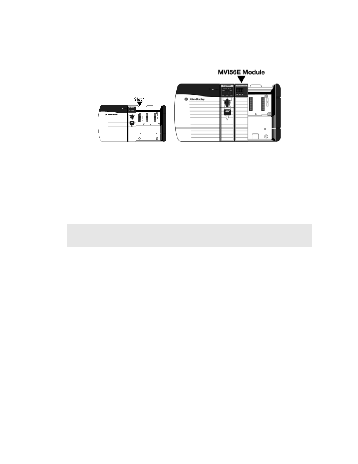
1 Align the module with the top and bottom guides, and then slide it into the
rack until the module is firmly against the backplane connector.
2 With a firm, steady push, snap the module into place.
3 Check that the holding clips on the top and bottom of the module are securely
in the locking holes of the rack.
4 Make a note of the slot location. You must identify the slot in which the
module is installed in order for the sample program to work correctly. Slot
numbers are identified on the green circuit board (backplane) of the
ControlLogix rack.
5 Turn power ON.
Note: If you insert the module improperly, the system may stop working or may
behave unpredictably.
1.6 Installing ProSoft Configuration Builder
To install ProSoft Configuration Builder from the web site
1 Download the latest version of PCB from www.prosoft-technology.com.
2 Run the install file. This action starts the installation wizard for ProSoft
Configuration Builder.
3 Click NEXT on each page of the installation wizard. Click FINISH on the last
page of the wizard.
ProSoft Technology, Inc. Page 15 of 155
Page 16

Start Here MVI56E-FLN ♦ ControlLogix Platform
User Manual FA Control Network Ethernet Communication Module
1.7 Connecting Your PC to the Module
The E1 port is for configuration only and cannot be used on the FL-net network.
The E2 port is for exclusive use on the FL-net network and cannot be used for
configuration.
To configure the module, once it is securely mounted, connect one end of an
Ethernet cable to the Config (E1) port and connect the other end to an Ethernet
hub or switch which is accessible from the same network as your personal
computer (PC). You can also connect directly from the Ethernet port on your PC
to the Config (E1) port on the module by using an Ethernet crossover cable (not
included).
Page 16 of 155 ProSoft Technology, Inc.
Page 17

MVI56E-FLN ♦ ControlLogix Platform Start Here
FA Control Network Ethernet Communication Module User Manual
1.8 Setting Up a Temporary IP Address
Important: ProSoft Configuration Builder locates MVI56E-FLN modules through
UDP broadcast messages. These messages may be blocked by routers or layer
3 switches. In that case, ProSoft Discovery Service will be unable to locate the
modules.
To use ProSoft Configuration Builder, arrange the Ethernet connection so that
there is no router/layer 3 switch between the computer and the module OR
reconfigure the router/layer 3 switch to allow the routing of the UDP broadcast
messages.
1 Click the START button, and then navigate to PROGRAMS / PROSOFT
TECHNOLOGY.
2 Click to start ProSoft Configuration Builder.
ProSoft Technology, Inc. Page 17 of 155
Page 18
Start Here MVI56E-FLN ♦ ControlLogix Platform
User Manual FA Control Network Ethernet Communication Module
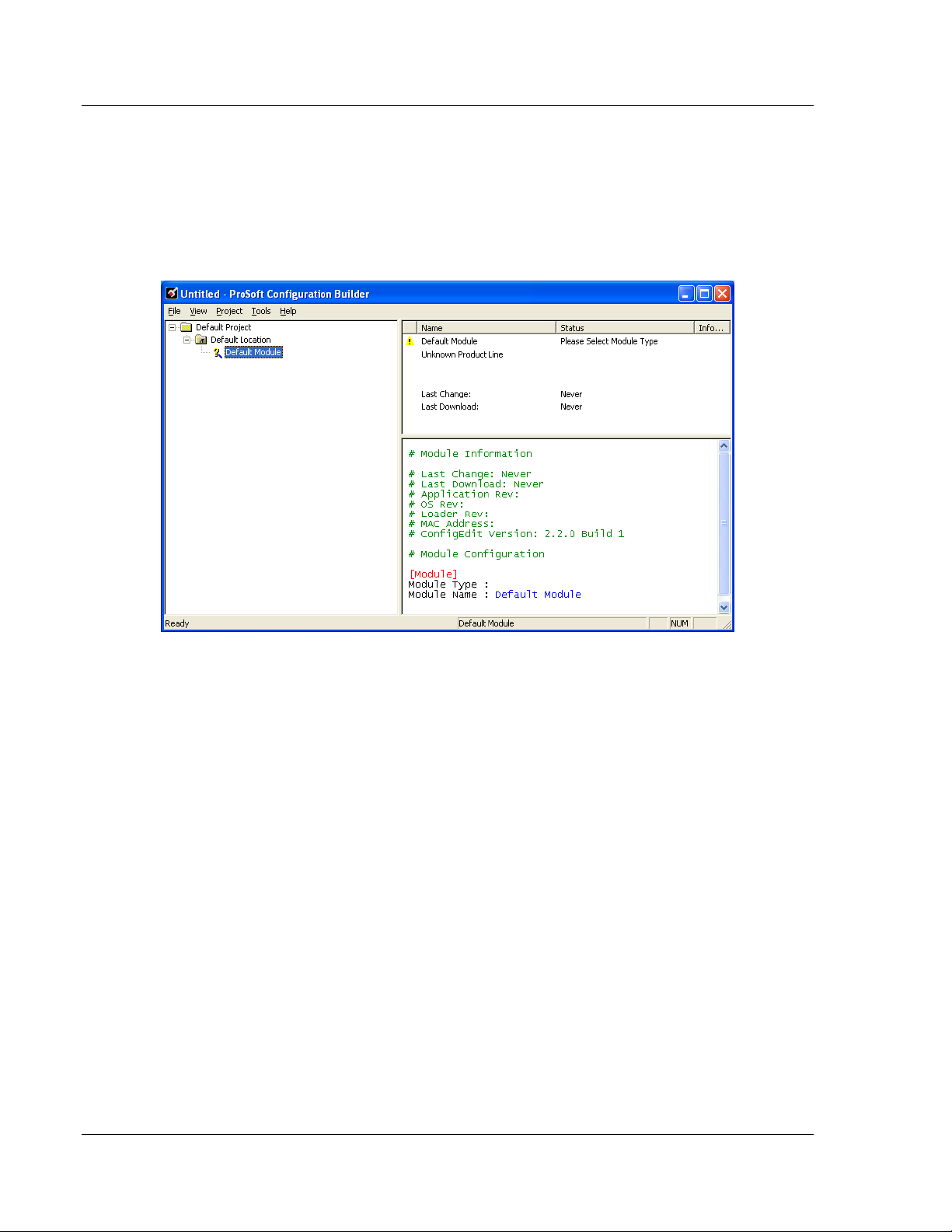
If you have used other Windows configuration tools before, you will find the
screen layout familiar. PCB’s window consists of a tree view on the left, and
an information pane and a configuration pane on the right side of the window.
When you first start PCB, the tree view consists of folders for DEFAULT
PROJECT and DEFAULT LOCATION, with a DEFAULT MODULE in the Default
Location folder. The following illustration shows the PCB window with a new
project.
3 Use the mouse to select DEFAULT MODULE in the tree view, and then click the
right mouse button to open a shortcut menu.
Page 18 of 155 ProSoft Technology, Inc.
Page 19

MVI56E-FLN ♦ ControlLogix Platform Start Here
FA Control Network Ethernet Communication Module User Manual
4 On the shortcut menu, select CHOOSE MODULE TYPE. This action opens the
Choose Module Type dialog box.
5 In the Product Line Filter area of the dialog box, select MVI56E. In the
SELECT MODULE TYPE dropdown list, select MVI56E-FLN, and then click OK
to save your settings and return to the ProSoft Configuration Builder window.
6 Right-click the module icon.
7 Click the SET UP CONNECTION button to browse for the module’s IP address.
ProSoft Technology, Inc. Page 19 of 155
Page 20

Start Here MVI56E-FLN ♦ ControlLogix Platform
User Manual FA Control Network Ethernet Communication Module
8 On the Connection Setup dialog box, click the TEST CONNECTION button to
verify if the module is accessible with the current settings
9 If PCB is still unable to connect to the module, click the BROWSE DEVICE(S)
button to open the ProSoft Discovery Service.
10 Select the module, then right-click and choose ASSIGN TEMPORARY IP.
11 The module’s default IP address is 192.168.0.250.
12 Choose an unused IP within your subnet, and then click OK.
Page 20 of 155 ProSoft Technology, Inc.
Page 21

MVI56E-FLN ♦ ControlLogix Platform Start Here
FA Control Network Ethernet Communication Module User Manual
13 On the shortcut menu, choose DIAGNOSTICS.
This action opens the Diagnostics dialog box.
ProSoft Technology, Inc. Page 21 of 155
Page 22

Start Here MVI56E-FLN ♦ ControlLogix Platform
User Manual FA Control Network Ethernet Communication Module
1.9 Connecting to the Module's Web Page
1 In ProSoft Discovery Service, select the MVI56E-FLN module, and then click
the right mouse button to open a shortcut menu.
2 On the shortcut menu, choose VIEW MODULE’S WEBPAGE.
The Web page contains general product information, firmware download link, and
links to ProSoft Technology's Web site.
Important: The temporary IP address is only valid until the next time the module
is initialized. Please refer to Setting Up a Temporary IP Address (page 17) in the
MVI56E-FLN User Manual for information on how to set the module’s permanent
IP address.
Page 22 of 155 ProSoft Technology, Inc.
Page 23

MVI56E-FLN ♦ ControlLogix Platform Start Here
FA Control Network Ethernet Communication Module User Manual
1.10 Using the RSLogix 5000 Sample Project
1.10.1 Opening the Sample Ladder Logic
The sample program for your MVI56E-FLN module includes custom tags, data
types and ladder logic for data I/O and status monitoring. For most applications,
you can run the sample ladder program without modification, or, for advanced
applications, you can incorporate the sample program into your existing
application.
The version number appended to the file name corresponds with the firmware
version number of your ControlLogix processor. The firmware version and
sample program version must match.
Determining the Firmware Version of Your Processor
Important: The RSLinx service must be installed and running on your computer
in order for RSLogix to communicate with the processor. Refer to your RSLinx
and RSLogix documentation for help configuring and troubleshooting these
applications.
1 Connect an RS-232 serial cable from the COM (serial) port on your PC to the
communication port on the front of the processor.
2 Start RSLogix 5000 and close any existing project that may be loaded.
3 Open the COMMUNICATIONS menu and choose GO ONLINE. RSLogix will
establish communication with the processor. This may take a few moments.
4 When RSLogix has established communication with the processor, the
Connected To Go Online dialog box will open.
ProSoft Technology, Inc. Page 23 of 155
Page 24

Start Here MVI56E-FLN ♦ ControlLogix Platform
User Manual FA Control Network Ethernet Communication Module
5 On the Connected To Go Online dialog box, click the GENERAL tab. This tab
shows information about the processor, including the Revision (firmware)
version. In the following illustration, the firmware version is 17.2.
Page 24 of 155 ProSoft Technology, Inc.
Page 25

MVI56E-FLN ♦ ControlLogix Platform Start Here
FA Control Network Ethernet Communication Module User Manual
Selecting the Slot Number for the Module
This sample application is for a module installed in Slot 1 in a ControlLogix rack.
The ladder logic uses the slot number to identify the module. If you are installing
the module in a different slot, you must update the ladder logic so that program
tags and variables are correct, and do not conflict with other modules in the rack.
Changing the slot number
1 In the Controller Organization list, select the module and then click the right
mouse button to open a shortcut menu.
2 On the shortcut menu, choose PROPERTIES. This action opens the Module
Properties dialog box.
3 In the Slot field, use the spinners on the right side of the field to select the slot
number where the module will reside in the rack, and then click OK.
RSLogix will automatically apply the slot number change to all tags, variables
and ladder logic rungs that use the MVI56E-FLN slot number for computation.
ProSoft Technology, Inc. Page 25 of 155
Page 26
Start Here MVI56E-FLN ♦ ControlLogix Platform
User Manual FA Control Network Ethernet Communication Module
Configuring the RSLinx Driver for the PC COM Port
If RSLogix is unable to establish communication with the processor, follow these
steps.
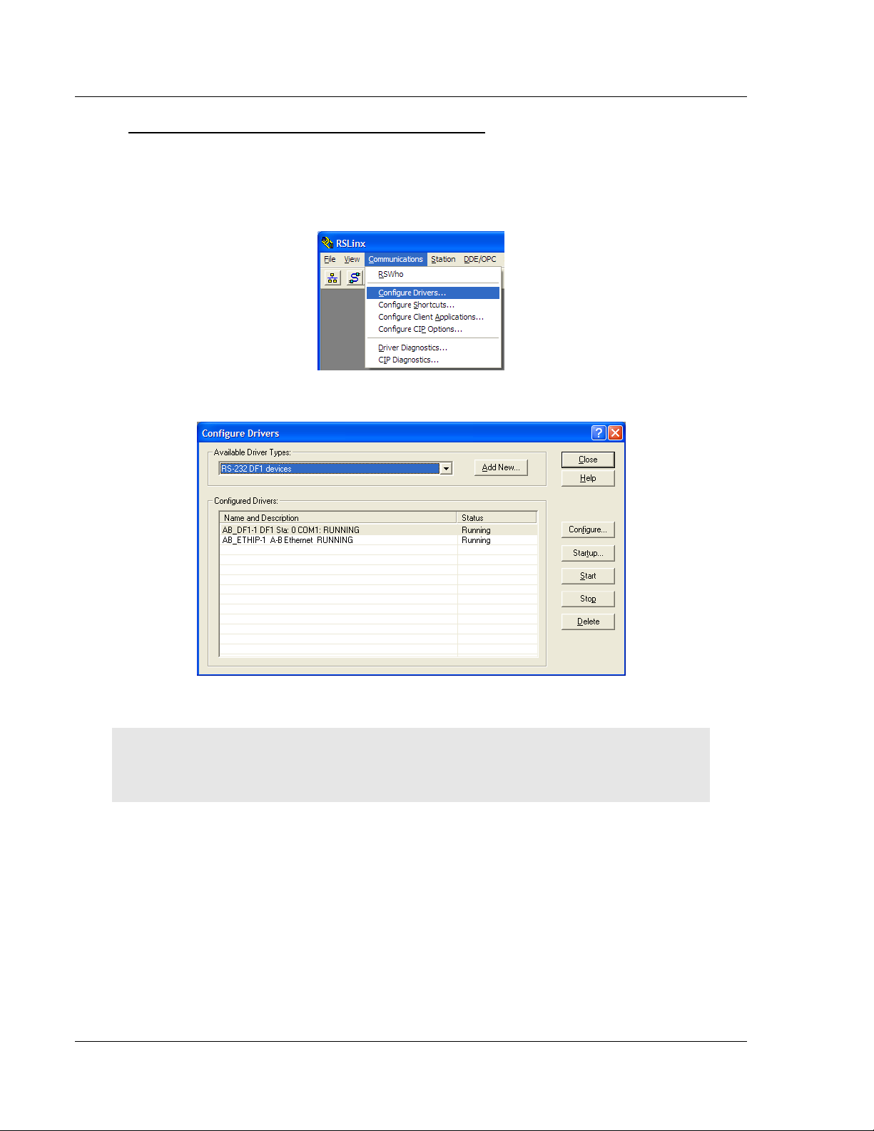
1 Open RSLinx.
2 Open the COMMUNICATIONS menu, and choose CONFIGURE DRIVERS.
This action opens the Configure Drivers dialog box.
Note: If the list of configured drivers is blank, you must first choose and configure
a driver from the Available Driver Types list. The recommended driver type to
choose for serial communication with the processor is RS-232 DF1 Devices.
Page 26 of 155 ProSoft Technology, Inc.
Page 27
MVI56E-FLN ♦ ControlLogix Platform Start Here
FA Control Network Ethernet Communication Module User Manual
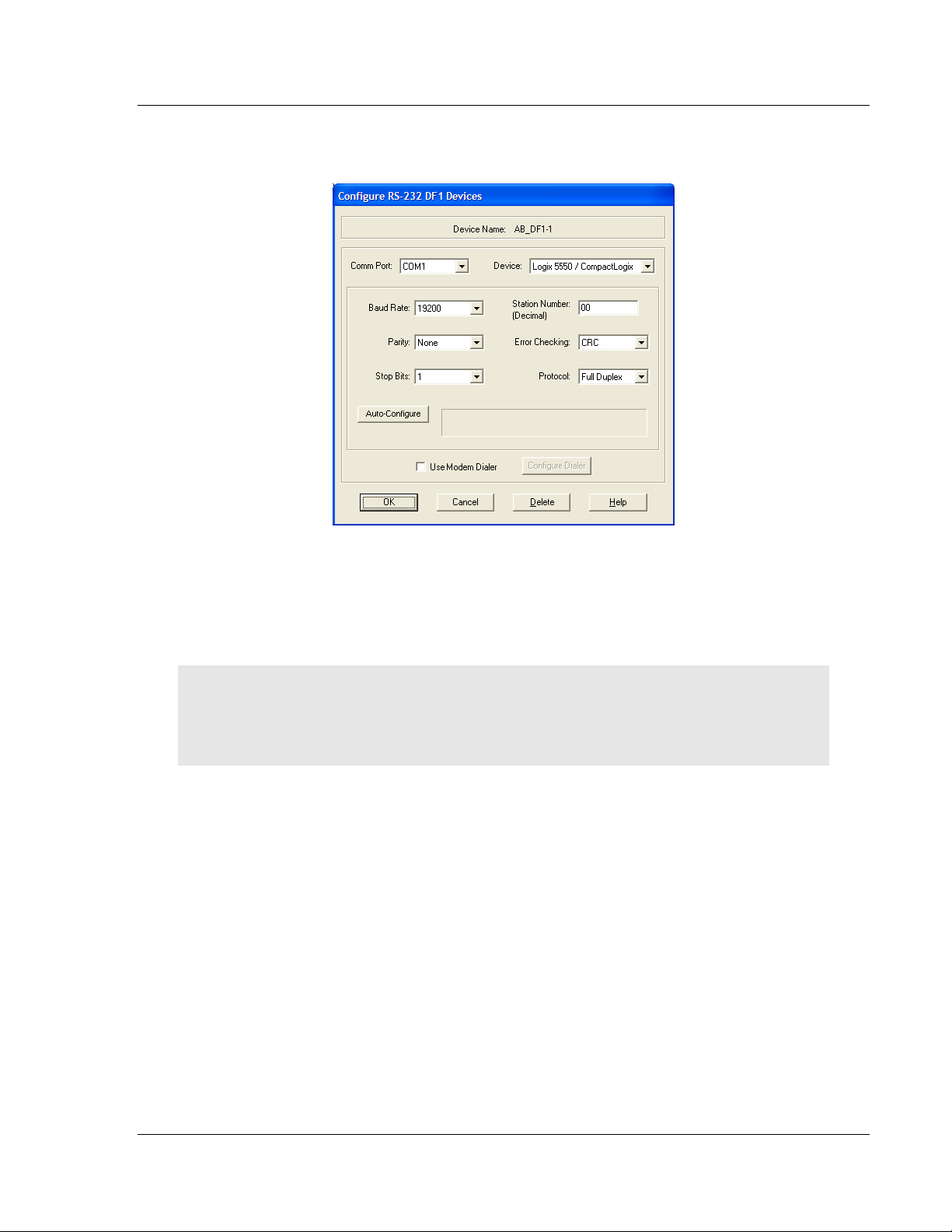
3 Click to select the driver, and then click CONFIGURE. This action opens the
Configure RS-232 DF1 Devices dialog box.
4 Click the AUTO-CONFIGURE button. RSLinx will attempt to configure your
serial port to work with the selected driver.
5 When you see the message Auto Configuration Successful, click the OK
button to dismiss the dialog box.
Note: If the auto-configuration procedure fails, verify that the cables are
connected correctly between the processor and the serial port on your computer,
and then try again. If you are still unable to auto-configure the port, refer to your
RSLinx documentation for further troubleshooting steps.
ProSoft Technology, Inc. Page 27 of 155
Page 28

Start Here MVI56E-FLN ♦ ControlLogix Platform
User Manual FA Control Network Ethernet Communication Module
1.10.2 Adding the Module to an Existing Project
1 Select the I/O Configuration folder in the Controller Organization window of
RSLogix 5000, and then click the right mouse button to open a shortcut
menu. On the shortcut menu, choose NEW MODULE.
This action opens the Select Module dialog box:
2 Select the 1756-MODULE (GENERIC 1756 MODULE) from the list and click OK.
This action opens the New Module dialog box.
Page 28 of 155 ProSoft Technology, Inc.
Page 29
MVI56E-FLN ♦ ControlLogix Platform Start Here
Parameter
Value
Name
Enter a module identification string. Example: FLN_2
Description
Enter a description for the module. Example: FA CONTROL
NETWORK COMMUNICATION MODULE
Comm Format
Select DATA-INT.
Slot
Enter the slot number in the rack where the MVI56E-FLN
module is located.
Input Assembly Instance
1
Input Size
250
Output Assembly Instance
2
Output Size
248
Configuration Assembly Instance
4
Configuration Size
0
FA Control Network Ethernet Communication Module User Manual
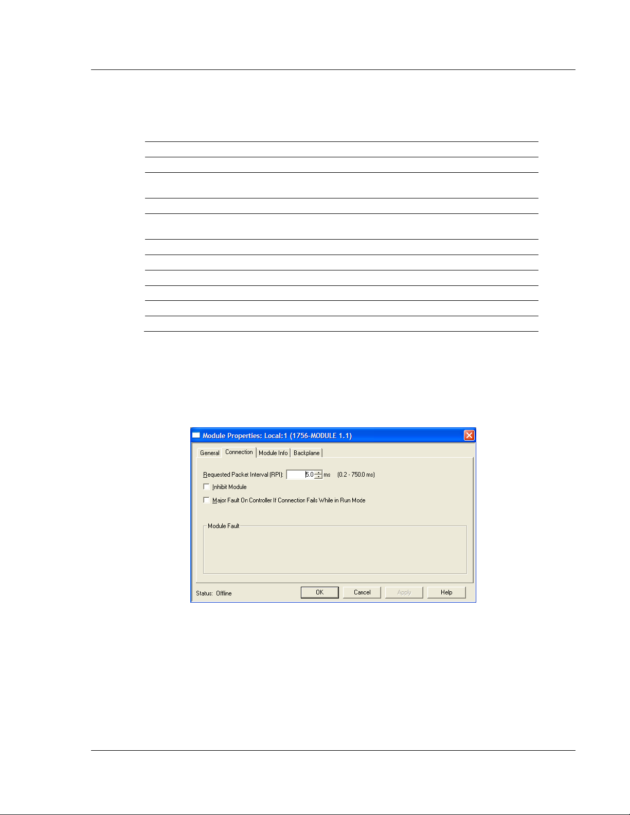
3 Enter the Name, Description and Slot options for your application. You must
select the Comm Format as DATA - INT in the dialog box, otherwise the
module will not communicate. Click OK to continue.
4 Select the Requested Packet Interval value for scanning the I/O on the
module. This value represents the minimum frequency that the module will
handle scheduled events. This value should not be set to less than 1
millisecond. The default value is 5 milliseconds. Values between 1 and 10
milliseconds should work with most applications.
ProSoft Technology, Inc. Page 29 of 155
Page 30
Start Here MVI56E-FLN ♦ ControlLogix Platform
User Manual FA Control Network Ethernet Communication Module
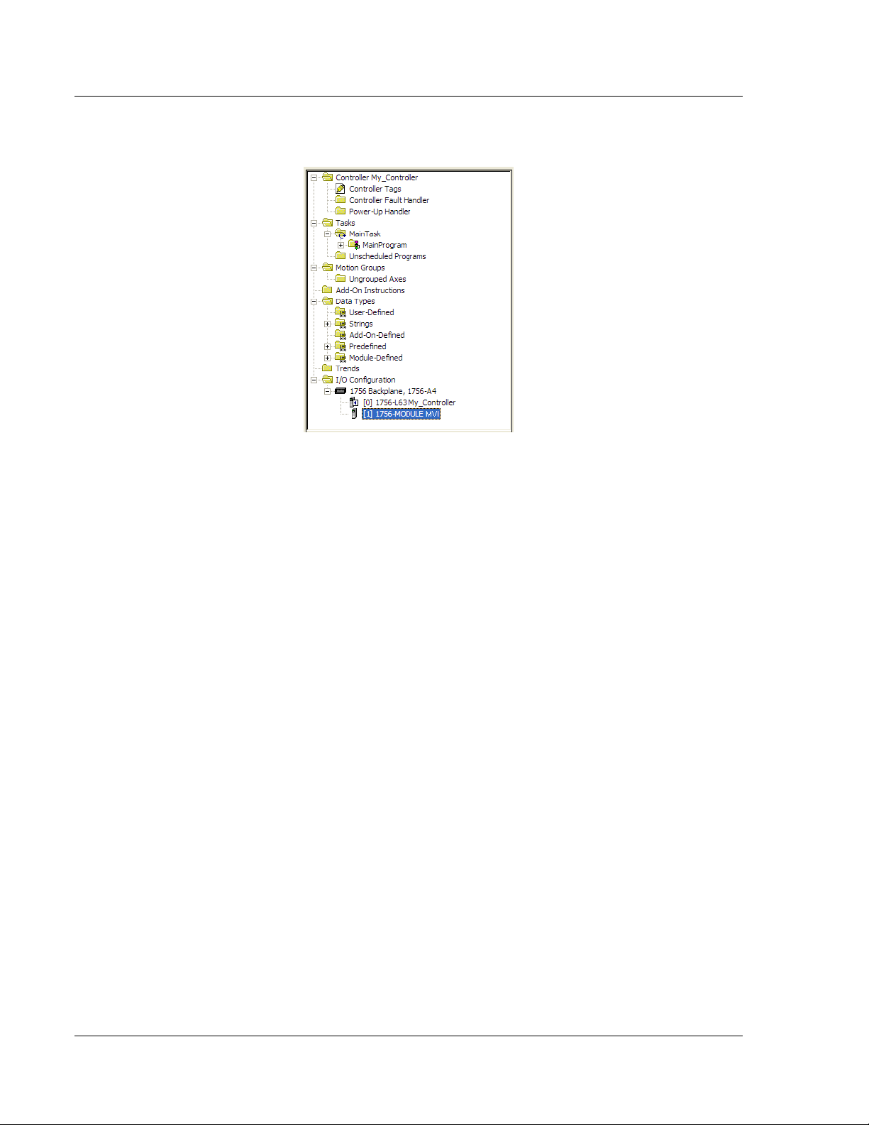
5 Save the module. Click OK to dismiss the dialog box. The Controller
Organization window now displays the module's presence.
6 Copy the User-Defined Data Types from the sample program into your
existing RSLogix 5000 project.
7 Copy the Controller Tags from the sample program into your project.
8 Copy the Ladder Rungs from the sample program into your project.
Page 30 of 155 ProSoft Technology, Inc.
Page 31

MVI56E-FLN ♦ ControlLogix Platform Start Here
FA Control Network Ethernet Communication Module User Manual
1.10.3 Connecting Your PC to the ControlLogix Processor
There are several ways to establish communication between your PC and the
ControlLogix processor. The following steps show how to establish
communication through the serial interface. It is not mandatory that you use the
processor's serial interface. You may access the processor through whatever
network interface is available on your system. Refer to your Rockwell Automation
documentation for information on other connection methods.
1 Connect the right-angle connector end of the cable to your controller at the
communications port.
2 Connect the straight connector end of the cable to the serial port on your
computer.
ProSoft Technology, Inc. Page 31 of 155
Page 32

Start Here MVI56E-FLN ♦ ControlLogix Platform
User Manual FA Control Network Ethernet Communication Module
1.10.4 Downloading the Sample Program to the Processor
Note: The key switch on the front of the ControlLogix processor must be in the
REM or PROG position.
1 If you are not already online with the processor, open the Communications
menu, and then choose DOWNLOAD. RSLogix 5000 will establish
communication with the processor. You do not have to download through the
processor's serial port, as shown here. You may download through any
available network connection.
2 When communication is established, RSLogix 5000 will open a confirmation
dialog box. Click the DOWNLOAD button to transfer the sample program to the
processor.
3 RSLogix 5000 will compile the program and transfer it to the processor. This
process may take a few minutes.
4 When the download is complete, RSLogix 5000 will open another
confirmation dialog box. If the key switch is in the REM position, click OK to
switch the processor from PROGRAM mode to RUN mode.
Note: If you receive an error message during these steps, refer to your RSLogix
documentation to interpret and correct the error.
Page 32 of 155 ProSoft Technology, Inc.
Page 33

MVI56E-FLN ♦ ControlLogix Platform Configuring the MVI56E-FLN Module
In This Chapter
Using ProSoft Configuration Builder Software ....................................... 33
Module Configuration ............................................................................ 36
Downloading the Project to the Module ................................................. 42
Configuring the FL-net Device ............................................................... 44
Verifying Communication....................................................................... 51
FA Control Network Ethernet Communication Module User Manual
2 Configuring the MVI56E-FLN Module
The purpose of this section of the User Manual is to show the MVI56E-FLN
functionality through a typical real-world application. For this example application,
the MVI56E-FLN is shown communicating with a Toyoda FL/ET-T-V2
communication module that transfers the data to a TOYODA PC3JG-P processor
located on the same rack.
For this example, the MVI56E-FLN node address is 40, and the FL/ET-T-V2
module node address is 10.
2.1 Using ProSoft Configuration Builder Software
ProSoft Configuration Builder (PCB) provides a quick and easy way to manage
module configuration files customized to meet your application needs. PCB is not
only a powerful solution for new configuration files, but also allows you to import
information from previously installed (known working) configurations to new
projects.
Note: During startup and initialization, the MVI56E-FLN module receives its
protocol and backplane configuration information from the installed Personality
Module (Compact Flash). Use ProSoft Configuration Builder to configure module
settings and to download changes to the Personality Module.
ProSoft Technology, Inc. Page 33 of 155
Page 34

Configuring the MVI56E-FLN Module MVI56E-FLN ♦ ControlLogix Platform
User Manual FA Control Network Ethernet Communication Module
2.1.1 Setting Module Parameters
Notice that the contents of the information pane and the configuration pane
changed when you added the MVI56E-FLN module to the project.
At this time, you may wish to rename the Default Project and Default Location
folders in the tree view.
Renaming an Object
1 Select the object, and then click the right mouse button to open a shortcut
menu. From the shortcut menu, choose RENAME.
2 Type the name to assign to the object.
3 Click away from the object to save the new name.
Configuring Module Parameters
1 Click on the [+] sign next to the module icon to expand module information.
2 Click on the [+] sign next to any icon to view module information and
configuration options.
3 Double-click any icon to open an Edit dialog box.
4 To edit a parameter, select the parameter in the left pane and make your
changes in the right pane.
5 Click OK to save your changes.
Page 34 of 155 ProSoft Technology, Inc.
Page 35

MVI56E-FLN ♦ ControlLogix Platform Configuring the MVI56E-FLN Module
FA Control Network Ethernet Communication Module User Manual
Creating Optional Comment Entries
1 Click the [+] to the left of the icon to expand the module
comments.
2 Double-click the icon. The Edit - Module Comment dialog box
appears.
3 Enter your comment and click OK to save your changes.
Printing a Configuration File
1 Select the module icon, and then click the right mouse button to open a
shortcut menu.
2 On the shortcut menu, choose VIEW CONFIGURATION. This action opens the
View Configuration window.
3 In the View Configuration window, open the FILE menu, and choose PRINT.
This action opens the Print dialog box.
4 In the Print dialog box, choose the printer to use from the drop-down list,
select printing options, and then click OK.
ProSoft Technology, Inc. Page 35 of 155
Page 36

Configuring the MVI56E-FLN Module MVI56E-FLN ♦ ControlLogix Platform
User Manual FA Control Network Ethernet Communication Module
2.2 Module Configuration
2.2.1 FL-net
Configure the module to properly transfer data between the ControlLogix
processor and the remote FL-net node (Toyoda PLC - TPLC).
Node Name
Up to 10 ASCII characters
This is a user-defined node identification.
It can be set from the upper layer or by a network parameter write message.
When it is set from the network by using message transmission, the node does
not secede from the network if only the node name is changed, continuing
communication.
Page 36 of 155 ProSoft Technology, Inc.
Page 37

MVI56E-FLN ♦ ControlLogix Platform Configuring the MVI56E-FLN Module
Parameter Range (Words)
Top Address
Area Size
Area 1
0 to 511
0 to 512
Area 2
0 to 8191
0 to 8192
FA Control Network Ethernet Communication Module User Manual
Area Parameters
The ranges of the top addresses (starting adresses) and sizes of Common
Memory Areas 1 and 2 are as follows.
These parameters can be set from the upper layer or by a network parameter
write message.
When nodes receive a network parameter write message for setting these
parameters, the node secedes from the network and rejoins the network in the
halfway participation status.
Unless they are set from the upper layer, the node is regarded as having no
transmitting area. At this time, however, a token is exchanged.
Configuring Area 1 and Area 2
Each area is defined by its starting address (top address) and word length (size).
The following illustration shows the starting addresses and word lengths used in
the sample application:
ProSoft Technology, Inc. Page 37 of 155
Page 38

Configuring the MVI56E-FLN Module MVI56E-FLN ♦ ControlLogix Platform
User Manual FA Control Network Ethernet Communication Module
Use the following settings to configure the data to transfer from the module to the
remote node. This data is transferred from the ControlLogix processor to the
MVI56E-FLN module through the FLNETDATA.Output.Area1 and
FLNETDATA.Output.Area2 controller tag arrays.
Area 1 Top : 0
Area 1 Size : 50
Area 2 Top : 0
Area 2 Size : 100
Use the following settings to configure the data to transfer from the Common
Memory to the processor. This data is transferred from the MVI56E-FLN module
to the ControlLogix processor through the FLNETDATA.Input.Area1 and
FLNETDATA.Input.Area2 controller tag arrays.
BP Area 1 Top : 50
BP Area 1 Size : 50
BP Area 2 Top : 100
BP Area 2 Size : 100
The next illustration shows how the data is transferred through the module
between Common Memory and the ControlLogix processor controller tags
arrays:
Page 38 of 155 ProSoft Technology, Inc.
Page 39

MVI56E-FLN ♦ ControlLogix Platform Configuring the MVI56E-FLN Module
FA Control Network Ethernet Communication Module User Manual
Token Watchdog Time
1 to 255 milliseconds
The Token Watchdog Time (also known as Token Monitoring Time) value is
unique for each node and is set from the FA link protocol upper layer as the initial
value. If this value is not set, the node is inoperable.
The Token Watchdog Time is notified to all nodes as information on the frame
header. Each node uses the value on the frame from each node as a value of the
monitoring time until the token-holding node releases the token.
Minimum Frame Interval Time
0 to 50 (in units of 100 milliseconds)
This interval value is a unique for each node and is set from the FA link protocol
upper layer as the initial value. If this value is not set, the node is inoperable.
The allowable minimum frame interval means
The time interval between reception of a token by a node and and
transmission of any frame from the node
or
The time interval between frames transmitted (from the end of the previous
frame until the beginning of the next frame) The allowable minimum frame
interval of each node is notified to all nodes as information on the frame
header. Each node obtains the maximum value from it and recognizes it as
the allowable minimum frame interval to use.
Important Note: For this module to operate correctly on an FL-net network, the
Minimum Frame Interval Time must be set to a value of 20 or more for all nodes
on the network. If nodes on the network have values less than 20 for this
parameter, the module may not be able to join the network.
ProSoft Technology, Inc. Page 39 of 155
Page 40

Configuring the MVI56E-FLN Module MVI56E-FLN ♦ ControlLogix Platform
User Manual FA Control Network Ethernet Communication Module
2.2.2 Ethernet Configuration
Use this procedure to modify the temporary Ethernet settings you set for your
module in the section on Setting Up a Temporary IP Address (page 17). Here
you assign two sets of IP address, subnet mask, and gateway address values,
one for each of the two Ethernet ports on the module. The IP address for
module's E1 port, which is used exclusively for configuring the module, is entered
in the my_ip parameter set. The IP address for the module's E2 port, which is
used exclusively for the FL-net network data transfer application, is entered in the
my_ip1 parameter set.
1 Determine the network settings for the two ports on your module, with the
help of your network administrator if necessary. You will need the following
information:
For the configuration port E1:
o my_ip - IP address (fixed IP req.) _____ . _____ . _____ . _____
o netmask - Subnet mask _____ . _____ . _____ . _____
o gateway - Gateway address _____ . _____ . _____ . _____
For the FL-net application port E2:
o my_ip1 - IP address (fixed IP req.) _192_ . _168_ . _250_ . _XXX_
o netmask - Subnet mask _____ . _____ . _____ . _____
o gateway - Gateway address _____ . _____ . _____ . _____
Note: The gateway address is optional, and is not required for networks that do
not use a default gateway.
The last octet of the my_ip1 address (XXX, above) will be the module's FL-net
node address on the FA Control network.
Note: Both IP addresses must be configured for different networks. This module
will communicate if both IP addresses are located in the same network.
Page 40 of 155 ProSoft Technology, Inc.
Page 41

MVI56E-FLN ♦ ControlLogix Platform Configuring the MVI56E-FLN Module
Node number
Applications
1 to 249
Used for standard FL-net (Version 2.00) devices.
250 to 254
Used for FL-net (Version 2.00) maintenance purposes.
255
Reserved for internal system use (used for broadcasting not available to
users).
0
Reserved for internal system use.
FA Control Network Ethernet Communication Module User Manual
2 Double-click the ETHERNET CONFIGURATION icon. This action opens the Edit
dialog box.
3 Edit the values.
4 When you are finished editing, click OK to save your changes and return to
the ProSoft Configuration Builder main window.
Node Number
A device's node number is the last octet of its IP address.
Without a node number, the node is inoperable. If, while joining a network, a
node detects another node with an identical node number, it will not transmit any
data on the network.
ProSoft Technology, Inc. Page 41 of 155
Page 42

Configuring the MVI56E-FLN Module MVI56E-FLN ♦ ControlLogix Platform
User Manual FA Control Network Ethernet Communication Module
2.3 Downloading the Project to the Module
In order for the module to use the settings you configured, you must download
(copy) the updated Project file from your PC to the module.
1 In the tree view in ProSoft Configuration Builder, click once to select the
MVI56E-FLN module.
2 Open the PROJECT menu, and then choose MODULE / DOWNLOAD.
This action opens the Download dialog box. Notice that the Ethernet address
field contains the IP address you assigned in the previous step or the
temporary IP you assigned in the previous chapter. ProSoft Configuration
Builder will use this IP or temporary IP address to connect to the module.
Click TEST CONNECTION to verify that the IP address is allows access to the
module.
3 If the connection succeeds, click DOWNLOAD to transfer the Ethernet
configuration to the module.
Page 42 of 155 ProSoft Technology, Inc.
Page 43

MVI56E-FLN ♦ ControlLogix Platform Configuring the MVI56E-FLN Module
FA Control Network Ethernet Communication Module User Manual
If the Test Connection procedure fails, you will see an error message. To correct
the error, follow these steps.
1 Click OK to dismiss the error message.
2 On the Download dialog box, click BROWSE DEVICES to open ProSoft
Discovery Service.
3 Select the module, and then click the right mouse button to open a shortcut
menu. On the shortcut menu, choose SELECT FOR PCB.
4 Close ProSoft Discovery Service.
5 Click DOWNLOAD to transfer the configuration to the module.
ProSoft Technology, Inc. Page 43 of 155
Page 44

Configuring the MVI56E-FLN Module MVI56E-FLN ♦ ControlLogix Platform
Switch Positions
I/O module
ID Code
Link Memory
Capacity
Data Link Capacity (maximum number of
total words in reception and transmission
areas)
1 & 2 off
C9
8 kbytes
Relay link: 2048 points (128 words) (*2)
Register link: 2048 words (*1)
1 off, 2
on
D9
16 kbytes
Relay link: 2048 points (128 words) (*2)
Register link: 6144 words (* 1)
1 & 2 on
E9
32 kbytes
Relay link: 2048 points (128 words) (*2)
Register link: 8192 words (*1)
1 on, 2
off
B3
4 kbytes
The module is operated as Ethernet.
User Manual FA Control Network Ethernet Communication Module
2.4 Configuring the FL-net Device
2.4.1 Setting Up the FL/ET-T-V2 Module
Setting Operation Mode Switch
Select the correct operation mode through the switch (item 3 below)
The following options are available. This procedure will consider the first option
(ID Code = C9 - 8kbytes of Link Memory Capacity)
Page 44 of 155 ProSoft Technology, Inc.
Page 45

MVI56E-FLN ♦ ControlLogix Platform Configuring the MVI56E-FLN Module
FA Control Network Ethernet Communication Module User Manual
2.4.2 FL/ET-V2 Configuration with PCwin
Specifying I/O Module ID Code
1 Expand the Parameter folder, and double-click I/O MODULE.
ProSoft Technology, Inc. Page 45 of 155
Page 46

Configuring the MVI56E-FLN Module MVI56E-FLN ♦ ControlLogix Platform
User Manual FA Control Network Ethernet Communication Module
2 Select the FL-net module.
Setting Up the FL/ET-V2 Link Parameters
1 Double-click LINK PARAMETER.
Page 46 of 155 ProSoft Technology, Inc.
Page 47

MVI56E-FLN ♦ ControlLogix Platform Configuring the MVI56E-FLN Module
FA Control Network Ethernet Communication Module User Manual
2 Select the link number to assign to the FL/ET-T-V2 module. For this example,
use Link No 1 for the FL/ET-T-V2 module. Double click the link row and
configure the correct slot, rack and module for link 1 as shown in the following
illustrations:
ProSoft Technology, Inc. Page 47 of 155
Page 48

Configuring the MVI56E-FLN Module MVI56E-FLN ♦ ControlLogix Platform
User Manual FA Control Network Ethernet Communication Module
3 Click the DETAIL button to configure the following link parameters:
Node Number = 10
Communication Method = N:N or 1:N (Master)
4 Click the DATA LINK button to configure the common memory that will be
shared by all participating nodes in communication.
Page 48 of 155 ProSoft Technology, Inc.
Page 49

MVI56E-FLN ♦ ControlLogix Platform Configuring the MVI56E-FLN Module
FA Control Network Ethernet Communication Module User Manual
For this example, the data transfer takes place as described in the following
illustration (the Transmit Area in the TOYODA PLC must be configured inside
the Link Area):
5 Click OK to close the Data Link window, and then click the NETWORK button.
Configure the default parameters as shown in the following illustration:
Note: This configuration sets the node address of the FL/ET-T-V2 module to
192.168.250.10 (the node address was configured as 10).
ProSoft Technology, Inc. Page 49 of 155
Page 50

Configuring the MVI56E-FLN Module MVI56E-FLN ♦ ControlLogix Platform
User Manual FA Control Network Ethernet Communication Module
For this example, the processor (rack 0 and slot 0) will be assigned as DLNKM2. For more information about this topic, refer to the TOYODA PLC
documentation.
2.4.3 Downloading the Project
Now save the project and download it to the TOYODA PLC.
2.4.4 Connecting the MVI56E-FLN Module to the FL/ET-T-V2
Use standard CA5 Ethernet cables to connect the Ethernet port on the MVI56EFLN through a 10 Megabit Ethernet hub or switch to the Ethernet port on the
FL/ET-T-V2 module.
Warning: The MVI56E-FLN module is NOT compatible with Power Over
Ethernet (IEEE802.3af / IEEE802.3at) networks. Do NOT connect the module to
Ethernet devices, hubs, switches or networks that supply AC or DC power over
the Ethernet cable. Failure to observe this precaution may result in damage to
hardware, or injury to personnel.
Page 50 of 155 ProSoft Technology, Inc.
Page 51

MVI56E-FLN ♦ ControlLogix Platform Configuring the MVI56E-FLN Module
FA Control Network Ethernet Communication Module User Manual
2.5 Verifying Communication
This section shows how to monitor the communication status of the configured
FL-net network (assuming that both the FL/ET-T-V2 module and the MVI56EFLN module were configured according to the previous sections).
2.5.1 Using the Diagnostics Menu in ProSoft Configuration Builder
To connect to the module’s Configuration/Debug Ethernet port:
1 In ProSoft Configuration Builder, select the module, and then click the right
mouse button to open a shortcut menu.
2 On the shortcut menu, choose DIAGNOSTICS.
This action opens the Diagnostics dialog box.
ProSoft Technology, Inc. Page 51 of 155
Page 52

Configuring the MVI56E-FLN Module MVI56E-FLN ♦ ControlLogix Platform
User Manual FA Control Network Ethernet Communication Module
If there is no response from the module:
1 Click the SET UP CONNECTION button to browse for the module’s IP address.
2 In the Connection Setup dialog box, click the TEST CONNECTION button to
verify if the module is accessible with the current settings.
Page 52 of 155 ProSoft Technology, Inc.
Page 53

MVI56E-FLN ♦ ControlLogix Platform Configuring the MVI56E-FLN Module
FA Control Network Ethernet Communication Module User Manual
If PCB is still unable to connect to the module:
1 Click the BROWSE DEVICE(S) button to open the ProSoft Discovery Service.
Select the module, then right-click and choose SELECT FOR PCB.
2 Close ProSoft Discovery Service, and click the CONNECT button again.
3 If all of these troubleshooting steps fail, verify that the Ethernet cable is
connected properly between your computer and the module, either through a
hub or switch (using a standard Ethernet cable) or directly between your
computer and the module (using an Ethernet crossover-cable).
If you are still not able to establish a connection, contact ProSoft Technology for
assistance.
ProSoft Technology, Inc. Page 53 of 155
Page 54

Configuring the MVI56E-FLN Module MVI56E-FLN ♦ ControlLogix Platform
User Manual FA Control Network Ethernet Communication Module
2.5.2 The Diagnostics Menu
The following sections describe several items in the Diagnostics menu useful for
verifying communication in a newly set-up module. For information on the
remaining menu items, see Diagnostics Menu Items.
The Diagnostics menu for this module is arranged as a tree structure, with the
Main menu at the top of the tree, and one or more submenus for each menu
command. The first menu you see when you connect to the module is the Main
menu.
Page 54 of 155 ProSoft Technology, Inc.
Page 55

MVI56E-FLN ♦ ControlLogix Platform Configuring the MVI56E-FLN Module
Word
0
Bit #
0 1 2 3 4 5 6 7 8 9 10
11
12
13
14
15
Node #
0 1 2 3 4 5 6 7 8 9 10
11
12
13
14
15
Word
1
Bit #
0 1 2 3 4 5 6 7 8 9 10
11
12
13
14
15
Node #
16
17
18
19
20
21
22
23
24
25
26
27
28
29
30
31
Word
2
Bit #
0 1 2 3 4 5 6 7 8 9 10
11
12
13
14
15
Node #
32
33
34
35
36
37
38
39
40
41
42
43
44
45
46
47
FA Control Network Ethernet Communication Module User Manual
Checking the Nodes Exchanging Data
From the FL-NET submenu select NODE EXCHANGING DATA. This screen
contains a table which indicates all nodes that are exchanging data with the
MVI56E-FLN module.
Each four-digit number in the table is a hexadecimal word (16 bits) which
represents a bit sequence that corresponds to the status of each FL-net node.
The following tables show the correlation between the bits and the nodes on the
FL-net network for the first three words.
The following illustration shows that Node 10 is in data exchange mode. The
value 0400 hex indicates that Bit 10 is set with a value of 1, and all other bits
have a value of 0.
ProSoft Technology, Inc. Page 55 of 155
Page 56

Configuring the MVI56E-FLN Module MVI56E-FLN ♦ ControlLogix Platform
Word
0
Bit #
0 1 2 3 4 5 6 7 8 9 10
11
12
13
14
15
Node #
0 1 2 3 4 5 6 7 8 9 10
11
12
13
14
15
Word
1
Bit #
0 1 2 3 4 5 6 7 8 9 10
11
12
13
14
15
Node #
16
17
18
19
20
21
22
23
24
25
26
27
28
29
30
31
Word
2
Bit #
0 1 2 3 4 5 6 7 8 9 10
11
12
13
14
15
Node #
32
33
34
35
36
37
38
39
40
41
42
43
44
45
46
47
User Manual FA Control Network Ethernet Communication Module
Checking the Participating Nodes
From the FL-NET submenu select NODES PARTICIPATING. This screen contains a
table which indicates all participating nodes on the network.
Each four-digit number in the table is a hexadecimal word (16 bits) which
represents a bit sequence that corresponds to the status of each FL-net node.
The following tables show the correlation between the bits and the nodes on the
FL-net network for the first three words.
The following illustration shows that Nodes 10 and 40 are participating; a value of
0400 hex in Word 0 indicates that Bit 10 is set with a value of 1 and a value of
0100 hex in Word 2 indicates that Bit 40 is set with a value of 1.
Page 56 of 155 ProSoft Technology, Inc.
Page 57

MVI56E-FLN ♦ ControlLogix Platform Configuring the MVI56E-FLN Module
FA Control Network Ethernet Communication Module User Manual
Checking the Log Data
From the FL-NET submenu select LOG DATA 1 or LOG DATA 2 to display
information pertaining to:
Transmission
Reception
Cyclic Transmission
ProSoft Technology, Inc. Page 57 of 155
Page 58

Configuring the MVI56E-FLN Module MVI56E-FLN ♦ ControlLogix Platform
User Manual FA Control Network Ethernet Communication Module
Checking the Network Status
From the FL-NET submenu select NETWORK STATUS to display network
information:
Token-holding node number
Minimum Frame Interval Time
Refresh Cycle Time
Refresh Cycle Measurement Time
Page 58 of 155 ProSoft Technology, Inc.
Page 59

MVI56E-FLN ♦ ControlLogix Platform Configuring the MVI56E-FLN Module
FA Control Network Ethernet Communication Module User Manual
Checking the Own Node Data
From the FL-NET submenu select OWN NODE DATA to view settings and status
information for the MVI56E-FLN module.
ProSoft Technology, Inc. Page 59 of 155
Page 60

Configuring the MVI56E-FLN Module MVI56E-FLN ♦ ControlLogix Platform
User Manual FA Control Network Ethernet Communication Module
Checking the Participating Node Status
From the FLN-NET PARTICIPATION LIST submenu select NODES 0-127 and
NODES 128-255 to view settings and status information for each participating
node on the network.
Page 60 of 155 ProSoft Technology, Inc.
Page 61

MVI56E-FLN ♦ ControlLogix Platform Configuring the MVI56E-FLN Module
FA Control Network Ethernet Communication Module User Manual
2.5.3 Checking Status through ControlLogix Controller Tags
You can also monitor network status through the ControlLogix controller tags that
are updated through the MVI56E-FLN sample ladder. Refer to the web site at
www.prosoft-technology.com (http://www.prosoft-technology.com) for the sample
ladder logic for the MVI56E-FLN module.
THE FLNETSTATUS controller tag contains status information that is copied
from the module and the processor.
Checking the Own Node Status
Monitor the FLNETSTATUS.Own_node controller tag for MVI56E-FLN status
information. This tag includes the upper layer status (UL), allowable minimum
frame interval time (MFT), token watchdog time (TW), protocol, Area 1 and Area
2 settings for the MVI56E-FLN.
The information in this tag is updated automatically from the module through
status blocks 0 and -1.
ProSoft Technology, Inc. Page 61 of 155
Page 62

Configuring the MVI56E-FLN Module MVI56E-FLN ♦ ControlLogix Platform
User Manual FA Control Network Ethernet Communication Module
Checking the Nodes Exchanging Data
Monitor the FLNETSTATUS.General.Nodes_Exchanging_Data_Table[ ]
controller tag to see if each node is currently exchanging data. The following
illustration shows that only node 10 is currently exchanging data with the
MVI56E-FLN module: bit 10 of
FLNETSTATUS.General.Nodes_Exchanging_Data_Table[0] word is set to 1 (hex
value of 0400). The information in this tag is updated automatically from the
module through status blocks 0 and -1.
Page 62 of 155 ProSoft Technology, Inc.
Page 63

MVI56E-FLN ♦ ControlLogix Platform Configuring the MVI56E-FLN Module
FA Control Network Ethernet Communication Module User Manual
Checking the Participation Table
Monitor the FLNETSTATUS.General.Nodes_Participating_Count controller tag to
see the number of nodes currently participating in the network. The information in
this tag is updated automatically from the module through status blocks 0 and -1.
Monitor the FLNETSTATUS.General.Nodes_Participating_Table[ ] controller tag
to check if each node is currently participating in the FL-net network. The
following illustration shows that only nodes 10 and 40 are participating.
Bit 10 of FLNETSTATUS.General.Nodes_Exchanging_Data_Table[0] word is
set as 1 (hex value of 0400)
Bit 8 of FLNETSTATUS.General.Nodes_Exchanging_Data_Table[2] word is
set as 1 (hex value of 0100).
Bit 8 of FLNETSTATUS.General.Nodes_Exchanging_Data_Table[2]
corresponds with bit 40 for the entire participating table.
The following illustration shows that currently there are 2 nodes participating.
ProSoft Technology, Inc. Page 63 of 155
Page 64

Configuring the MVI56E-FLN Module MVI56E-FLN ♦ ControlLogix Platform
User Manual FA Control Network Ethernet Communication Module
Checking the Participating Node Status
To retrieve the participation node status, the processor must request special
block 2000 (Participation Table Request) from the module. This special block
transfer request allows the processor to retrieve status information for each
participating node. Status registers include:
upper layer status (ULS)
allowable minimum frame interval time (MFT)
allowable refresh cycle time (RCT)
Area 1 (A1) and Area 2 (A2) settings
token watchdog time (TW).
Each block can retrieve status for up to 10 participating nodes. The user
application must initially select the number of nodes to retrieve (up to 10) and the
first node address to retrieve.
For example, to retrieve the status for participating node address 10 (1 node
only), set the controller tags as shown in the following illustrations:
Next, trigger the Participation Table Request block (block 2000). To do this, set
the FLNETMODULE.CONTROL.GetParticipation bit to 1. The following rung in
the sample ladder WriteData routine performs the request to the module. The
FLNETMODULE.CONTROL.GetParticipation bit is automatically cleared after the
response is received from the module.
The following rung in the Read Data routine reads the module response
containing the participating node status.
Page 64 of 155 ProSoft Technology, Inc.
Page 65

MVI56E-FLN ♦ ControlLogix Platform Configuring the MVI56E-FLN Module
FA Control Network Ethernet Communication Module User Manual
Note: The sample ladder will copy the status for 10 nodes. Edit this logic
according to the number of nodes to be read for your application.
ProSoft Technology, Inc. Page 65 of 155
Page 66

Configuring the MVI56E-FLN Module MVI56E-FLN ♦ ControlLogix Platform
User Manual FA Control Network Ethernet Communication Module
The participating node status is read to the FLNETSTATUS.Participation[ ]
controller tag array. The status for node address 10 is available at
FLNETSTATUS.Participation[0].
Page 66 of 155 ProSoft Technology, Inc.
Page 67

MVI56E-FLN ♦ ControlLogix Platform Configuring the MVI56E-FLN Module
FA Control Network Ethernet Communication Module User Manual
Checking the Log Data
To retrieve the Log Data, the processor must request special block 9250 (Log
Data Block) from the module.
The following rung in the Write Data routine requests block 9250. To trigger this
logic, set the FLNETMODULE.CONTROL.GetParticipation bit to 1.
The processor will eventually receive the block response from the module, and
the following rung in the Write Data routine will automatically clear the
FLNETMODULE.CONTROL.GetParticipation bit and read the block response to
the correct tags.
ProSoft Technology, Inc. Page 67 of 155
Page 68

Configuring the MVI56E-FLN Module MVI56E-FLN ♦ ControlLogix Platform
User Manual FA Control Network Ethernet Communication Module
You can view the Log Data read from the module in the FLNETSTATUS.LogData
controller tag, as shown in the following illustration:
Page 68 of 155 ProSoft Technology, Inc.
Page 69

MVI56E-FLN ♦ ControlLogix Platform Configuring the MVI56E-FLN Module
FA Control Network Ethernet Communication Module User Manual
Checking the General Network Status
Monitor the FLNETSTATUS.Network for general FL-net network information:
the token node that is currently holding the token
the refresh cycle measurement time (RMT) - minimum, maximum and current
values
allowable minimum frame interval time (MFT)
allowable refresh cycle time (RCT).
This information is available in the FLNETSTATUS.Network controller tag.
Checking the Backplane status
Monitor the FLNETSTATUS.Backplane controller tag for information about
backplane status.
ProSoft Technology, Inc. Page 69 of 155
Page 70

Configuring the MVI56E-FLN Module MVI56E-FLN ♦ ControlLogix Platform
User Manual FA Control Network Ethernet Communication Module
2.5.4 Transferring Data
The sample ladder logic automatically updates the data with the
FLNETDATA.Output and FLNETDATA.Input controller tags. The Area 1 data is
divided into blocks 1 to 3. The Area 2 data is divided into blocks 4 to 35. Each
block contains up to 240 words of data.
The data received from the remote FL-net node to the MVI56E-FLN module is
automatically "reassembled" from the input blocks into the FLNETDATA.Intput
controller tag (according to each block ID). Also, the data to transfer from the
module to the remote FL-net node is copied from the FLNETDATA.Output
controller tag into the output blocks according to its block ID. This logic is already
handled by the sample ladder program supplied by ProSoft.
For this example, use the following MVI56E-FLN Area1 and Area 2 settings in
the FLNET.CFG configuration file:
Area 1 Top : 0 #0...511 top address for area 1
Area 1 Size : 50 #0...512 area 1 data size in words (0=not used)
Area 2 Top : 0 #0...8191 top address for area 1
Area 2 Size : 100 #0...8192 area 2 data size in words (0=not used)
BP Area 1 Top : 50 #0...511 top address for area 1
BP Area 1 Size: 50 #0...512 area 1 data size in words (0=none transferred)
BP Area 2 Top : 100 #0...8191 top address for area 1
BP Area 2 Size: 100 #0...8192 area 2 data size in words (0=none transferred)
Important: The module only generates the blocks required to transfer the data
you configured. For this example only one Area 1 block and one Area 2 blocks
are required, so only blocks 1 to 4 are used for data transfer. The larger the
areas, the more blocks are required to transfer data (and the more time is
required to update the whole block).
In this example, configure the FL/ET-T-V2 module with the values in the following
illustration:
Page 70 of 155 ProSoft Technology, Inc.
Page 71

MVI56E-FLN ♦ ControlLogix Platform Configuring the MVI56E-FLN Module
FA Control Network Ethernet Communication Module User Manual
Transferring Data from MVI56E-FLN (Area 1) to FL/ET-T-V2 Module (Relay
Area)
The FLNETDATA.Output.Area1 controller tags transfer data from the module
Area 1 to the remote FL-net node Relay link area. For this example, use the
values in the following illustration:
Use the PCWin Register Address Monitor to monitor the value set by the module
(address L00W for our example).
ProSoft Technology, Inc. Page 71 of 155
Page 72

Configuring the MVI56E-FLN Module MVI56E-FLN ♦ ControlLogix Platform
User Manual FA Control Network Ethernet Communication Module
Transferring Data from FL/ET-T-V2 Link Area to MVI56E-FLN Area 1
Use the PCWin Register Address Monitor to set the value to transfer to the
module (address L32W for this example)
Use FLNETDATA.Input.Area1 controller tags to monitor data received from the
remote node to the MVI56E-FLN Area 1.
Page 72 of 155 ProSoft Technology, Inc.
Page 73

MVI56E-FLN ♦ ControlLogix Platform Configuring the MVI56E-FLN Module
FA Control Network Ethernet Communication Module User Manual
Transferring Data from MVI56E-FLN (Area 2) to FL/ET-T-V2 module (Register
Area)
Use the FLNETDATA.Output.Area2 controller tags to transfer data from the
module Area 1 to the remote FL-net node Relay link area. For this example, use
the values in the following illustration:
Use the PCWin Register Address Monitor to monitor the value set by the module
(address R000 for our example).
ProSoft Technology, Inc. Page 73 of 155
Page 74

Configuring the MVI56E-FLN Module MVI56E-FLN ♦ ControlLogix Platform
User Manual FA Control Network Ethernet Communication Module
Transferring Data from FL/ET-T-V2 Register Area to MVI56E-FLN Area 2
Use the PCWin Register Address Monitor to set the value to transfer to the
module (address R0064 for this example)
Use the FLNETDATA.Input.Area2 controller tags to monitor data received from
the remote node to the MVI56E-FLN Area 2.
Page 74 of 155 ProSoft Technology, Inc.
Page 75

MVI56E-FLN ♦ ControlLogix Platform Diagnostics and Troubleshooting
In This Chapter
Reading Status Data from the Module .................................................. 75
Diagnostics Menu Items ........................................................................ 78
LED Status Indicators ............................................................................ 81
Clearing a Fault Condition ..................................................................... 84
Troubleshooting ..................................................................................... 85
FA Control Network Ethernet Communication Module User Manual
3 Diagnostics and Troubleshooting
The module provides information on diagnostics and troubleshooting in the
following forms:
LED status indicators on the front of the module provide information on the
module’s status.
Status data contained in the module can be viewed in ProSoft Configuration
Builder through the Ethernet port.
Status data values are transferred from the module to the processor.
3.1 Reading Status Data from the Module
The MVI56E-FLN module returns a block of status data in the input image that
can be used to determine the module’s operating status. This data is transferred
from the module to the ControlLogix processor continuously. You can view this
data in the FLN.STATUS controller tag in the ladder logic.
If the Error/Status Pointer is enabled, the status data can also be found in the
Read Data area of the module’s database at a location specified by the
Error/Status Pointer configuration parameter.
The Configuration/Debug port provides the following functionality:
Full view of the module’s configuration data
View of the module’s status data
Version Information
Control over the module (warm boot, cold boot, transfer configuration)
Facility to upload and download the module’s configuration file
ProSoft Technology, Inc. Page 75 of 155
Page 76

Diagnostics and Troubleshooting MVI56E-FLN ♦ ControlLogix Platform
Bit
Message
Description
Value
0
Node address duplicate
(1=Error)
Indicates the management information on
node number conflicted to see whether any
node having the same node number as the
self node setting exists on the network or not.
0x0001
1
TW Error (1=Error)
Token watchdog time error flag indicates that
transmission processing fails to complete
within the token watchdog time set in the own
node
0x0002
2
Rx Wait Error (1=Error)
Indicates that no frame has been received at
network initialization, being a frame receive
waiting status.
0x0004
3
Initialization Error
(1=Error)
Indicates an error is found in an initial setting
or resetting parameter
0x0008
4
Reserved
0x0010
5
Reserved
0x0020
6
Reserved
0x0040
7
0x0080
User Manual FA Control Network Ethernet Communication Module
3.1.1 Own-Node Status information
The Own Node Status register (displayed on the Own Node Status menu)
contains the following information:
Own Status Byte
Page 76 of 155 ProSoft Technology, Inc.
Page 77

MVI56E-FLN ♦ ControlLogix Platform Diagnostics and Troubleshooting
Bit
Message
Description
Value
0
*Node Status (1=Out-ring,
0=In-ring)
Indicates whether the node is in-ringed or outringed
0x0001
1
*Communication Invalid
(1=Yes, 0=No)
0x0002
2
Always 0
0x0004
3
Always 0
0x0008
4
Upper Layer Error Signal
(1=Error)
Indicates that the updating of the existence
signal of the upper layer cannot be recognized
0x0010
5
Common Memory Valid
(1=Valid)
Indicates the cycle data is valid
0x0020
6
Common Memory Set
(1=Complete)
Indicates that the setting in the common
memory of the node is completed
0x0040
7
Address Overlap
(1=Error,0=No Error)
Indicates that there is a duplication in the
common memory among the nodes connected
to the network
0x0080
Bit
Message
Description
Value
0 to 11
Error Code (User Defined)
0x0001
12
reserved
0x1000
13
1=Warning, 0=No Warning
Bit 15 = 1
Bit 15 = 0
0x2000
The upper layer
program is running with
an error but both cyclic
data and message data
are guaranteed.
The upper layer
program is at a stop
with an error but both
cyclic data and
message data are
guaranteed.
14
1=Alarm, 0=No Alarm
Both cyclic data and
message data are not
guaranteed.
Both cyclic data and
message data are not
guaranteed.
0x4000
15
1=Run, 0=Stop
Run
Stop
0x8000
FA Control Network Ethernet Communication Module User Manual
Link Status Byte
The FA-Link Status register (displayed on the Own Node Status menu) contains
the following information:
*Only reported to the processor and not network where these bits are always
clear.
Upper Layer Status Word
The Upper Layer Status can be set by the ControlLogix processor to the module.
Refer to Upper Layer Status Read Definition (page 110) for more information.
ProSoft Technology, Inc. Page 77 of 155
Page 78

Diagnostics and Troubleshooting MVI56E-FLN ♦ ControlLogix Platform
User Manual FA Control Network Ethernet Communication Module
3.2 Diagnostics Menu Items
This section describes PCB Diagnostics menu items that were not addressed in
the chapter on Configuring the MVI56E-FLN Module. For general information on
accessing the Diagnostics menu, please refer to Using the Diagnostic Menu in
Prosoft Configuration Builder. For specific information on items in the FL-NET
submenu, please see The Diagnostics Menu (page 54).
3.2.1 Monitoring Module Information
Use the MODULE menu to view configuration and hardware information for the
MVI56E-FLN module’s backplane and Ethernet application port.
Viewing Version Information
From the MODULE submenu select VERSION to view module hardware and
firmware information.
The values on this menu correspond with the contents of the module’s general
product information registers.
Page 78 of 155 ProSoft Technology, Inc.
Page 79

MVI56E-FLN ♦ ControlLogix Platform Diagnostics and Troubleshooting
FA Control Network Ethernet Communication Module User Manual
Viewing Configuration Information
From the MODULE submenu select CONFIG to view backplane configuration
settings for the MVI56E-FLN module.
This information corresponds with the FL-NET configuration settings in ProSoft
Configuration Builder (page 36).
ProSoft Technology, Inc. Page 79 of 155
Page 80

Diagnostics and Troubleshooting MVI56E-FLN ♦ ControlLogix Platform
User Manual FA Control Network Ethernet Communication Module
3.2.2 Monitoring Backplane Information
Use the BACKPLANE menu to view the backplane status information for the
MVI56E-FLN module.
Viewing Backplane Status
From the BACKPLANE submenu select STATUS to view current backplane
status, including
Number of retries
Backplane Status
Fail Count
Number of words read
Number of words written
Number of words parsed
Error count
Event count
Command count
During normal operation, the Read, Write, and Parsing values should increment
continuously, while the error value should not increment.
The status values on this menu correspond with the members of the MVI56EFLN Status object.
Page 80 of 155 ProSoft Technology, Inc.
Page 81

MVI56E-FLN ♦ ControlLogix Platform Diagnostics and Troubleshooting
Code
Message
Boot / DDOK
Module is initializing
Ladd
Module is waiting for required module configuration data from
ladder logic to configure the application port(s)
Waiting for Processor Connection
Module did not connect to processor during initialization
Sample ladder logic or AOI is not loaded on processor
Module is located in a different slot than the one
configured in the ladder logic/AOI
Processor is not in RUN or REM RUN mode
Last config: <date>
Indicates the last date when the module changed its IP
address. You can update the module date and time through the
module’s web page, or with the optional MVI56E Advanced
Add-On Instruction.
C0 (Client): CmdCnt: X MinDly :
X CmdOffs: X RespTmout : X
Retries : X ErrOffs : X
ARPTmout : X ErrDelay : X
FltFlag : X FltSt : X FltOffs : X
SVR (server) : BIOffs: X WIOffs :
X OutOffs : X HoldOffs : X
FltFlag : X FltSt : X FltSt : X
CommTmout : X
After power up and every reconfiguration, the module will
display the configuration of the application port(s). The
information consists of:
Client
CmdCnt : number of commands configured for the Client
MinDly : Minimum Command Delay parameter
CmdOffs : Command Error Pointer parameter
RespTmout : Response Timeout parameter
Retries : Retry Count parameter
ErrOffs : Error/Status Offset parameter
ARPTmout : ARP Timeout parameter
ErrDelay: Command Error Delay parameter
FltFlag: Float Flag parameter
Flt St : Float Start parameter
FltOffs : Float Offset parameter
Server
BIOffs: Bit Input Offset parameter
WIOffs : Word Input Offset parameter
OutOffs : Output offset parameter
HoldOffs : Holding Register offset parameter
FltFlag: Float Flag parameter
FltSt : Float Start parameter
FltOffs : Float Offset parameter
FA Control Network Ethernet Communication Module User Manual
3.3 LED Status Indicators
3.3.1 Scrolling LED Status Indicators
The scrolling LED display indicates the module's operating status as follows:
Initialization Messages
ProSoft Technology, Inc. Page 81 of 155
Page 82

Diagnostics and Troubleshooting MVI56E-FLN ♦ ControlLogix Platform
Code
Message
<Backplane Status>
OK: Module is communicating with processor
ERR: Module is unable to communicate with processor. For
this scenario, the <Port Status> message above is replaced
with "Processor faulted or is in program mode".
<IP Address>
Module IP address
<C0>
OK: Port is communicating without error
Communication Errors: port is having communication errors.
Refer to Diagnostics and Troubleshooting (page 75) for further
information about the error.
LED
State
Description
Data
OFF
Ethernet connected at 10Mbps duplex speed
AMBER Solid
Ethernet connected at 100Mbps duplex speed
Link
OFF
No physical network connection is detected. No Ethernet
communication is possible. Check wiring and cables.
GREEN Solid
or Blinking
Physical network connection detected. This LED must be ON solid
for Ethernet communication to be possible.
User Manual FA Control Network Ethernet Communication Module
Operation Messages
After the initialization step, the following message pattern will be repeated.
<Backplane Status> <IP Address> <Backplane Status> <Port Status>
3.3.2 Ethernet LED Indicators
The Ethernet LEDs indicate the module's Ethernet port status as follows:
Page 82 of 155 ProSoft Technology, Inc.
Page 83

MVI56E-FLN ♦ ControlLogix Platform Diagnostics and Troubleshooting
LED Label
Color
Status
Indication
LER
(FL-net Link
Status LED)
Red or
Green
OFF
The module is not receiving adequate power or is not securely
plugged into the rack. May also be OFF during configuration
download.
GREEN
The MVI56E-FLN is 'in-ring' and working normally.
RED
The most common cause is that the module has detected a
communication error during operation of its application port.
The following conditions may also cause a RED LED:
The module is 'out-ring' or has a duplicate node number
(Watchdog timeout error or Wait error may cause this)
The module is rebooting due to a ColdBoot or WarmBoot
request from the ladder logic or Debug Menu
The firmware is initializing during startup
The firmware detects an on-board hardware problem
during startup
Failure of application port hardware during startup
The module is shutting down
OK
Red or
Green
OFF
The module is not receiving adequate power or is not securely
plugged into the rack.
GREEN
The module is operating normally.
RED
The module is initializing, has detected an internal error, or is
re-booting. If the LED remains RED for over 10 seconds, the
module is not working. Remove it from the rack and re-insert it
to restart its internal program.
FA Control Network Ethernet Communication Module User Manual
3.3.3 Non-Scrolling LED Status Indicators
The non-scrolling LEDs indicate the module’s operating status as follows:
ProSoft Technology, Inc. Page 83 of 155
Page 84

Diagnostics and Troubleshooting MVI56E-FLN ♦ ControlLogix Platform
User Manual FA Control Network Ethernet Communication Module
3.4 Clearing a Fault Condition
Typically, if the OK LED on the front of the module turns RED for more than ten
seconds, a hardware problem has been detected in the module or the program
has exited.
To clear the condition, follow these steps:
1 Turn off power to the rack.
2 Remove the card from the rack.
3 Verify that all jumpers are set correctly.
4 If the module requires a Compact Flash card, verify that the card is installed
correctly.
5 Re-insert the card in the rack and turn the power back on.
6 Verify correct configuration data is being transferred to the module from the
ControlLogix controller.
If the module's OK LED does not turn GREEN, verify that the module is inserted
completely into the rack. If this does not cure the problem, contact ProSoft
Technology Technical Support.
Page 84 of 155 ProSoft Technology, Inc.
Page 85

MVI56E-FLN ♦ ControlLogix Platform Diagnostics and Troubleshooting
Problem Description
Steps to take
Processor Fault
Verify that the module is plugged into the slot that has been configured
for the module in the I/O Configuration of RSLogix.
Verify that the slot location in the rack has been configured correctly in
the ladder logic.
Processor I/O LED
flashes
This indicates a problem with backplane communications. A problem
could exist between the processor and any installed I/O module, not just
the MVI56E-FLN. Verify that all modules in the rack are correctly
configured in the ladder logic.
Problem Description
Steps to take
MVI56E modules with
scrolling LED display:
<Backplane Status>
condition reads ERR
This indicates that backplane transfer operations are failing. Connect to
the module’s Configuration/Debug port to check this.
To establish backplane communications, verify the following items:
The processor is in RUN or REM RUN mode.
The backplane driver is loaded in the module.
The module is configured for read and write data block transfer.
The ladder logic handles all read and write block situations.
The module is properly configured in the processor I/O configuration
and ladder logic.
OK LED remains RED
The program has halted or a critical error has occurred. Connect to the
Configuration/Debug port to see if the module is running. If the program
has halted, turn off power to the rack, remove the card from the rack and
re-insert the card in the rack, and then restore power to the rack.
FA Control Network Ethernet Communication Module User Manual
3.5 Troubleshooting
Use the following troubleshooting steps if you encounter problems when the
module is powered up. If these steps do not resolve your problem, please contact
ProSoft Technology Technical Support.
Processor Errors
Module Errors
ProSoft Technology, Inc. Page 85 of 155
Page 86

Diagnostics and Troubleshooting MVI56E-FLN ♦ ControlLogix Platform
User Manual FA Control Network Ethernet Communication Module
Page 86 of 155 ProSoft Technology, Inc.
Page 87

MVI56E-FLN ♦ ControlLogix Platform Reference
In This Chapter
Product Specifications ........................................................................... 87
Functional Overview .............................................................................. 91
Implementation of FL-net..................................................................... 106
FL-net Protocol and Network ............................................................... 116
Error and Status Data .......................................................................... 128
FL-net Device Profile for MVI56E-FLN Module ................................... 129
Module Power Up ................................................................................ 132
State Transition Diagram ..................................................................... 132
Cable Connections - MVI56E-FLN ...................................................... 142
FA Control Network Ethernet Communication Module User Manual
4 Reference
4.1 Product Specifications
The MVI56E-FLN FA Control Network communication module is a single slot
solution that allows Rockwell Automation ControlLogix compatible processors to
easily interface with other FL-net protocol compatible devices. The module
implements FL-net version 2.00 (OPCN-2) defined by JEMA (The Japan
Electrical Manufacturers Association) for the standard FA control network. FL-net
is a master-less system.
The MVI56E-FLN module acts as a gateway between the FL-net network and the
ControlLogix backplane. The data transfer from the ControlLogix processor is
asynchronous from the actions on the FL-net network. The module’s internal
database can be used to exchange Area 1 and Area 2 cyclic, network, and
module status data between the processor and the FL-net network.
The MVI56E-FLN module accepts commands to control and monitor the data
stored in the databases. This data is passed between the module and the
ControlLogix processor over the backplane for use in user applications.
General features include:
Master-less token control method
ProSoft Technology, Inc. Page 87 of 155
FA link protocol on Ethernet UDP/IP
Cyclic data transfer: Supports virtual memory Area 1 and Area 2. The cyclic
data is mapped to the modules I/O area
Page 88

Reference MVI56E-FLN ♦ ControlLogix Platform
User Manual FA Control Network Ethernet Communication Module
4.1.1 Features
FL-net systems have the following features.
1 FL-net is an open system.
2 FL-net enables a multi-vendor network.
3 FL-net enables personal computers and FA controllers, such as
programmable controllers (PLCs) or computerized numeric controllers
(CNCs), by different manufacturers to be interconnected, controlled, and
monitored.
Master-less token control method.
FA link protocol on Ethernet UDP / IP.
Cyclic data transfer: Supports virtual memory Area 1 (512 words) and Area 2
(8192 words). The cyclic data is mapped to the modules I/O area.
Message transfer:
Server Functionality
o Log data read service
o Log data clear service
o Network Parameter Read
o Profile Read
o Return Message
Network Management Table: According to FL-net version 2.00 specification.
Own-node Management Table: According to FL-net version 2.00
specification.
Participating Node Management Table: According to FL-net version 2.00
specification.
Network configurable via a text file or ProSoft Technology Configuration
Builder Software
Status and Error information
The MVI56E-FLN module provides highly configurable FL-net capabilities to the
Allen-Bradley ControlLogix platform. FL-net (OPCN-2) is a controller-level
network conforming to specification Japan Electrical manufacturers Association
JEM1479. Developed by to focus on multi-vendor communications of
programmable controllers, NC controllers, Robotic and other Motion Control
systems.
Page 88 of 155 ProSoft Technology, Inc.
Page 89

MVI56E-FLN ♦ ControlLogix Platform Reference
Specification
Description
Backplane Current Load
800 mA @ 5 Vdc
3 mA @ 24 Vdc
Operating Temperature
0°C to 60°C (32°F to 140°F)
Storage Temperature
-40°C to 85°C (-40°F to 185°F)
Shock
30 g operational
50 g non-operational
Vibration: 5 g from 10 to 150 Hz
Relative Humidity
5% to 95% (without condensation)
LED Indicators
Battery Status (ERR)
Application Status (APP)
Module Status (OK)
4-Character, Scrolling, AlphaNumeric LED Display
Shows Module, Version, IP, Application Port
Setting, Port Status, and Error Information
Debug/Configuration Ethernet port (E1)
Ethernet Port
10/100 Base-T, RJ45 Connector, for CAT5 cable
Link and Activity LED indicators
Auto-crossover cable detection
FL-net Application Ethernet port (E2)
Ethernet Port
10 base-T, RJ45 Connector, for CAT5 cable
Link and Activity LED indicators
Auto-crossover cable detection
Shipped with Unit
Two, 5-foot Ethernet straight-through cables
FA Control Network Ethernet Communication Module User Manual
4.1.2 General Specifications
Backward compatible with previous MVI56-FLN versions
Single-slot 1756 ControlLogix backplane compatible
10/100 Mbps auto crossover detection Ethernet configuration and application
port
User-definable module data memory mapping of up to 5000 16-bit registers
ProSoft Configuration Builder (PCB) software supported, a Winows-based
graphical user interface providing simple product and network configuration
Sample ladder logic is used for data transfer between module and processor
Internal web server provides access to product documentation, module
status, diagnostics, and firmware updates
4-character, alpha-numeric, scrolling LED display of status and diagnostics
data in plain English – no cryptic error or alarm codes to decipher
ProSoft Discovery Service (PDS) software used to locate the module on the
network and assign temporary IP address
Personality Module - a non-volatile industrial-grade Compact Flash (CF) card
used to store network and module configuration, allowing quick in-the-field
product replacement by transferring the CF card
4.1.3 Hardware Specifications
ProSoft Technology, Inc. Page 89 of 155
Page 90

Reference MVI56E-FLN ♦ ControlLogix Platform
User Manual FA Control Network Ethernet Communication Module
4.1.4 Functional Specifications
The MVI56E-FLN module accepts commands to control and monitor the data
stored in the databases. This data is passed between the module and the
ControlLogix processor over the backplane for use in user applications.
Physical
ControlLogix Form Factor - Single-Slot
Connections:
o 1 - RJ45, 10 BaseT, 10 Mbps connection to the FA Control Ethernet
network (FL-net)
o 1 - RJ45, 10/100 BaseT, 10 or 100 Mbps Ethernet connection for
configuration
ControlLogix Interface
Operation via simple ladder logic
Complete set up and monitoring of module through ProSoft Configuration
Builder (PCB) software
ControlLogix backplane interface via I/O access
All data is contained in a single controller tag array
All status data is contained in a single controller tag array, with defined
objects to simplify monitoring and communicating with the module
Page 90 of 155 ProSoft Technology, Inc.
Page 91

MVI56E-FLN ♦ ControlLogix Platform Reference
FA Control Network Ethernet Communication Module User Manual
4.2 Functional Overview
4.2.1 About FL-net Protocol
FL-net is an open FA network that was standardized by the Japan FA Open
Systems Promotion Group (JOP) of the Manufacturing Science and Technology
Center (MSTC) under the Ministry of International Trade and Industry (MITI). It
has been established in the Japan Electrical Manufacturers standards (JEM
1479) and is becoming very popular.
FL-net enables personal computers and FA controllers, such as programmable
controllers (PLCs) or computerized numeric controllers (CNCs), by different
manufacturers to be interconnected, controlled, and monitored, as shown in the
following illustration.
The following illustration shows the positioning of the FL-net.
FL-net (Version 2.00) Unit specifications have been designed to conform to
Japan Electrical Manufacturers standards (JEM 1479: 2001). It cannot be
connected to communications devices based on the previous standards (JEM
1479: 2000).
The most recent FL-net specifications can be downloaded from the home page of
the Japan Electrical Manufacturers Association (http://www.jemanet.or.jp/Japanese/hyojun/opcn_e/opcn07.htm (http://www.jemanet.or.jp/japanese/hyojun/opcn_e/opcn07.htm)
ProSoft Technology, Inc. Page 91 of 155
Page 92

Reference MVI56E-FLN ♦ ControlLogix Platform
Multi-access data exchange
between controllers
Peer to peer messaging (read / write memory or
parameters)
User Manual FA Control Network Ethernet Communication Module
Data Communication Between Nodes
FL-net supports data communications by cyclic transmission and message
transmission.
Page 92 of 155 ProSoft Technology, Inc.
Page 93

MVI56E-FLN ♦ ControlLogix Platform Reference
FA Control Network Ethernet Communication Module User Manual
Cyclic Transmission
Cyclic transmission is used to exchange data between nodes. The data is shared
by each node through the Common Memory (shared memory) function.
Basic functions:
Cyclic transmission implements Common Memory interface.
Each node transmits its entire memory content while it holds the token.
Nodes having no cyclic data are acceptable.
With cyclic communications, the Common Memory is refreshed on a fixed cycle
time. Message communications are controlled so that the Common Memory
refresh time does not exceed the allowable refresh cycle time.
Each node constantly monitors the message communications frames that travel
through the network from the time it receives one local-node-directed token until
it receives the next local-node-directed token. When no message
communications frame travels through the network in a single cycle, 120% of the
cycle time value becomes the allowable refresh cycle time. In this way the
allowable refresh cycle time is actively determined according to the number of
nodes in the network.
ProSoft Technology, Inc. Page 93 of 155
Page 94

Reference MVI56E-FLN ♦ ControlLogix Platform
User Manual FA Control Network Ethernet Communication Module
Common Memory
The Common Memory interface provides nodes with a service that can be
regarded as a memory shared among them.
Data on the Common Memory is refreshed cyclically as each node updates
and broadcasts its memory contents.
Each node broadcasts its data in a fixed cycle and all the nodes in a network
share the same data on the Common Memory.
A user can use the Common Memory as global area in the node.
The Common Memory size is 8k bits + 8k words = 8.5k words in a whole
network.
Area 1 and Area 2
The Common Memory is divided into two areas.
Area 1 has 512 words and Area 2 has 8192 words (1 word = 2 bytes = 16
bits)
The maximum quantity of data that can be transmitted by a single node is
8.5k words.
Page 94 of 155 ProSoft Technology, Inc.
Page 95

MVI56E-FLN ♦ ControlLogix Platform Reference
FA Control Network Ethernet Communication Module User Manual
Node Data Area Assignment
Each node on a FL-net has a specific transmission area in the Common
Memory that does not overlap with others.
A transmission area assigned to one node must be a receiving area for other
nodes.
Two data areas can be assigned to a node within Area 1 and Area 2 of the
Common Memory.
Both areas can be assigned at any word-size within the maximum.
A node's memory assignment within a Common Memory area is defined by
the top address (starting address) and size of its data area.
Frame Transmission
Maximum data length of one message frame is 1024 bytes (excluding
header).
Multiple frames may be used if the transmitting area size exceeds the
maximum frame data size.
A node receiving multiple frames will update the area only after successfully
receiving all frames from the sending node. Thus time coherency of data from
a node is guaranteed.
ProSoft Technology, Inc. Page 95 of 155
Page 96

Reference MVI56E-FLN ♦ ControlLogix Platform
User Manual FA Control Network Ethernet Communication Module
Common Memory Function
A node can use the whole Common Memory as receiving area.
Node for Reception Only
Nodes can be set up to only receive data.
Page 96 of 155 ProSoft Technology, Inc.
Page 97

MVI56E-FLN ♦ ControlLogix Platform Reference
FA Control Network Ethernet Communication Module User Manual
Node Having No Common Memory
The FA link protocol allows for the existence of nodes that do not have Common
Memory because they only participate in message transmission, and do not
transmit and receive cyclic data.
ProSoft Technology, Inc. Page 97 of 155
Page 98

Reference MVI56E-FLN ♦ ControlLogix Platform
User Manual FA Control Network Ethernet Communication Module
User-Defined Specifications
User-defined specifications allow the following range of features that are required
for FA systems.
1 Large-scale network
Up to 254 devices (nodes) can be connected in the physical layer of the
network.
"1 through 254" shall be used as node number. However, numbers "250
through 254" are reserved for maintenance purposes. Number "0" shall not
be used.
Number "255" shall be used as the global address for broadcasting.
2 Dual communications functions to suit application
The Common Memory function uses cyclic transmission so that each node
can always share the same data with other nodes on the network. FL-net also
supports message communications for use when handling only essential data
is required.
3 Large-capacity Common Memory
The Common Memory is provided with a large capacity of 8K bits (Area 1)
and 8K words (Area 2).
4 High-speed response
High-speed response time of 50 milliseconds / 32 nodes (for 2K bits and 2K
words) is provided. The absence of a Master in the FL-net network enables
nodes to be added or removed readily without affecting any other nodes. This
allows any node to be turned ON or OFF easily and facilitates maintenance.
The FL-net protocol is characterized by the following items:
1 Transmission control using masterless token system avoids collision.
2 Refresh cycle time can be specified since the system circulates a token in a
fixed time.
3 The token is transmitted together with cyclic data.
4 The node with a smallest node number among those who participate the
network at start-up time shall start to send the token.
5 If no token is transmitted for a specified period, next node in the token
circulation ring shall send a new token.
6 The masterless token system (characterized by the above two items) will
keep the network from stopping in case of failure of some nodes.
7 The protocol provides information management tables for useful information
to refer operation status of other nodes such as operation mode (RUN /
STOP) and hardware malfunction (ALARM).
Page 98 of 155 ProSoft Technology, Inc.
Page 99

MVI56E-FLN ♦ ControlLogix Platform Reference
FA Control Network Ethernet Communication Module User Manual
4.2.2 Data Flow between Module and Processor
The following discussion outlines the flow of data between the two pieces of
hardware (ControlLogix processor and MVI56E-FLN module) and other nodes on
the TCP/IP network.
Module’s Cyclic Input Data
Module’s Cyclic Output Data
ProSoft Technology, Inc. Page 99 of 155
Page 100

Reference MVI56E-FLN ♦ ControlLogix Platform
Block Range
Descriptions
0 & -1
Status Data
1 to 3
Area 1 Data From Common Memory
4 to 35
Area 2 Data From Common Memory
1000 to 1004
Message Request ACK Blocks (future)
1100 to 1104
Message Response Blocks (future)
2000
Participation Table Response
9250
Log Data Block
Block Range
Descriptions
0 & -1
Empty Data Blocks
1 to 3
Area 1 Data To Common Memory
4 to 35
Area 2 Data To Common Memory
1000 to 1004
Message Request Blocks (future)
2000
Participation Table Request
9250
Log Data Block Request
9998
Warm-boot control block
9999
Cold-boot control block
User Manual FA Control Network Ethernet Communication Module
4.2.3 Backplane Data Transfer
Block Assignments
In order to exchange data with the processor, the MVI56E-FLN module supports
the following block. The block range refers to the Block ID used to identify each
block.
Input Data
Output Data
Page 100 of 155 ProSoft Technology, Inc.
 Loading...