

Page 1
MVI56E-AFC
Enhanced Liquid and Gas Flow
Computer for ControlLogix®
v4.04
October 2, 2018
SETUP AND CONFIGURATION GUIDE
Page 2

For professional users in the European Union
If you wish to discard electrical and electronic equipment (EEE), please contact your dealer or supplier
for further information.
Warning – Cancer and Reproductive Harm – www.P65Warnings.ca.gov
Your Feedback Please
We always want you to feel that you made the right decision to use our products. If you have suggestions, comments,
compliments or complaints about our products, documentation, or support, please write or call us.
ProSoft Technology, Inc.
+1 (661) 716-5100
+1 (661) 716-5101 (Fax)
www.prosoft-technology.com
support@prosoft-technology.com
© 2018 ProSoft Technology, Inc. All rights reserved.
October 2, 2018
ProSoft Technology®, is a registered copyright of ProSoft Technology, Inc. All other brand or product names are or
may be trademarks of, and are used to identify products and services of, their respective owners.
In an effort to conserve paper, ProSoft Technology no longer includes printed manuals with our product shipments.
User Manuals, Datasheets, Sample Ladder Files, and Configuration Files are available at:
www.prosoft-technology.com
Important Installation Instructions
Power, Input, and Output (I/O) wiring must be in accordance with Class I, Division 2 wiring methods, Article 501 to 4
(b) of the National Electrical Code, NFPA 70 for installation in the U.S., or as specified in Section 18-1J2 of the
Canadian Electrical Code for installations in Canada, and in accordance with the authority having jurisdiction. The
following warnings must be heeded:
WARNING - EXPLOSION HAZARD - SUBSTITUTION OF COMPONENTS MAY IMPAIR SUITABILITY FOR CLASS
I, DIV. 2.
WARNING - EXPLOSION HAZARD - WHEN IN HAZARDOUS LOCATIONS, TURN OFF POWER BEFORE
REPLACING OR WIRING MODULES.
WARNING - EXPLOSION HAZARD - DO NOT DISCONNECT EQUIPMENT UNLESS POWER HAS BEEN
SWITCHED OFF OR THE AREA IS KNOWN TO BE NON-HAZARDOUS.
Class 2
MVI (Multi Vendor Interface) Modules
WARNING - EXPLOSION HAZARD - DO NOT DISCONNECT EQUIPMENT UNLESS POWER HAS BEEN
SWITCHED OFF OR THE AREA IS KNOWN TO BE NON-HAZARDOUS.
AVERTISSEMENT - RISQUE D'EXPLOSION - AVANT DE DÉCONNECTER L'ÉQUIPEMENT, COUPER LE
COURANT OU S'ASSURER QUE L'EMPLACEMENT EST DÉSIGNÉ NON DANGEREUX.
Page 3

Warnings
North America Warnings
Power, Input, and Output (I/O) wiring must be in accordance with Class I, Division 2 wiring methods, Article 501 to 4
(b) of the National Electrical Code, NFPA 70 for installation in the U.S., or as specified in Section 18-1J2 of the
Canadian Electrical Code for installations in Canada, and in accordance with the authority having jurisdiction. The
following warnings must be heeded:
A Warning - Explosion Hazard - Substitution of components may impair suitability for Class I, Division 2.
B Warning - Explosion Hazard - When in hazardous locations, turn off power before replacing or rewiring modules.
C Warning - Explosion Hazard - Do not disconnect equipment unless power has been switched off or the area is
known to be non-hazardous.
Avertissement - Risque d'explosion - Avant de déconnecter l'équipement, couper le courant ou s'assurer que
l'emplacement est désigné non dangereux.
D Suitable for use in Class I, Division 2 Groups A, B, C and D Hazardous Locations or Non-Hazardous Locations.
ATEX Warnings and Conditions of Safe Usage
Power, Input, and Output (I/O) wiring must be in accordance with the authority having jurisdiction.
A Warning - Explosion Hazard - When in hazardous locations, turn off power before replacing or wiring modules.
B Warning - Explosion Hazard - Do not disconnect equipment unless power has been switched off or the area is
known to be non-hazardous.
C These products are intended to be mounted in an IP54 enclosure. The devices shall provide external means to
prevent the rated voltage being exceeded by transient disturbances of more than 40%. This device must be used
only with ATEX certified backplanes.
D DO NOT OPEN WHEN ENERGIZED.
Battery Life Advisory
The MVI46, MVI56, MVI56E, MVI69, and MVI71 modules use a rechargeable Lithium Vanadium Pentoxide battery to
back up the real-time clock and CMOS. The battery should last for the life of the module. The module must be
powered for approximately twenty hours before the battery becomes fully charged. After it is fully charged, the battery
provides backup power for the CMOS setup and the real-time clock for approximately 21 days. When the battery is
fully discharged, the module will revert to the default BIOS and clock settings.
Note: The battery is not user replaceable.
Electrical Ratings
Backplane Current Load: 800 mA @ 5.1 Vdc; 3 mA @ 24 Vdc
Operating Temperature: 0°C to 60°C (32°F to 140°F)
Storage Temperature: -40°C to 85°C (-40°F to 185°F)
Shock: 30 g, operational; 50 g, non-operational; Vibration: 5 g from 10 Hz to 150 Hz
Relative Humidity: 5% to 95% with no condensation
All phase conductor sizes must be at least 1.3 mm(squared) and all earth ground conductors must be at least
4mm(squared).
Agency Approvals and Certifications
Please visit our website: www.prosoft-technology.com
Page 4

Contents MVI56E-AFC ♦ Version 4.04
Contents
Your Feedback Please ........................................................................................................ 2
Important Installation Instructions ........................................................................................ 2
MVI (Multi Vendor Interface) Modules ................................................................................. 2
Warnings .............................................................................................................................. 3
Battery Life Advisory ............................................................................................................ 3
1 Before You Begin ..................................................................................... 9
Pre-Configuration Processes ..................................................................................... 9
Pre-Configuration Requirements ............................................................................. 10
Downloading EAFC Manager ............................................................................. 10
Downloading AOIs to your system ..................................................................... 11
Locating information for your meter type ................................................................. 12
Configuration Aids.................................................................................................... 14
Using the Modbus Dictionary ................................................................................... 16
Procedure ........................................................................................................... 18
2 Creating an EAFC Manager Project ...................................................... 21
Starting EAFC Manager ........................................................................................... 21
3 Configuring Site Parameters ................................ ................................. 23
Accessing Site Configuration Parameters ............................................................... 23
Configuring Site Options ..................................................................................... 26
Configuring Pass-thru Options ........................................................................... 27
Viewing Site Configuration Status ........................................................................... 27
UDT Tag Prefix ........................................................................................................ 28
Exporting UDT Files ............................................................................................ 29
Setting Communication Parameters ........................................................................ 31
Configuring Modbus TCP/IP ............................................................................... 33
Setting Whitelist Options .......................................................................................... 37
Advanced Tab ..................................................................................................... 38
Configuring Serial 1 and Serial 2 ........................................................................ 40
Poll Button ................................................................................................................ 44
Local Port Settings Dialog Box ................................................................................ 44
Read Button ............................................................................................................. 45
Write Button ............................................................................................................. 45
Special Wnd Button ................................................................................................. 45
Done Button ............................................................................................................. 46
Remapping Button ................................................................................................... 46
Accessing the Data .................................................................................................. 46
Site Status ................................................................................................................ 46
4 Configuring Meter Parameters .............................................................. 47
Prerequisites ............................................................................................................ 47
Page 4 of 149 ProSoft Technology, Inc.
October 2, 2018
Page 5

MVI56E-AFC ♦ Version 4.04 Contents
What Parameters Do I Have to Configure? ............................................................. 47
Configuring Meter and Stream Identification Parameters ....................................... 48
Setting End of Period Parameters ...................................................................... 49
Setting a Stream Name ...................................................................................... 51
Configuring Meter Type, Product Group, Units, and Primary Input ......................... 52
Selecting and Configuring Meter Type, Product Group, Units and Primary Input
Parameters .............................................................................................................. 53
Product Group .................................................................................................... 55
System of Units ................................................................................................... 55
5 Configuring Common Parameters ......................................................... 57
Selecting the Physical Device .................................................................................. 58
Specifying Reference Temperature and Pressure (Reference Conditions) ............ 60
Setting Accumulators and Flow Rates ..................................................................... 61
Flow Rate Period Unit ......................................................................................... 61
Flow Rate Unit .................................................................................................... 61
Accumulation Unit ............................................................................................... 62
Accumulator Rollover.......................................................................................... 62
Configuring Process Input Scaling........................................................................... 63
Zero Scale .......................................................................................................... 63
Full Scale ............................................................................................................ 63
Enabling/Disabling the Meter (Control Opts) ........................................................... 64
Backplane Return .................................................................................................... 64
Process Inputs .................................................................................................... 64
Component Analysis Function Block .................................................................. 64
Configuring Calculation Options .............................................................................. 66
Configuring Resettable Accumulators ..................................................................... 67
Non-Resettable Accumulators ............................................................................ 68
Resettable Accumulators .................................................................................... 69
Net Accumulator Calculation .............................................................................. 74
Accumulator Totalizer and Residue .................................................................... 75
Meter Factors ........................................................................................................... 75
Meter Alarm Control Options ................................................................................... 76
Setting Stream Options and Enabling/Disabling Meters ......................................... 78
ProSoft Technology, Inc. Page 5 of 149
October 2, 2018
Page 6

Contents MVI56E-AFC ♦ Version 4.04
6 Configuring Differential Meter Parameters ........................................... 81
7 Configuring Linear Meter Pulse Count Options ................................... 85
8 Configuring Linear Meter Pulse Frequency Options ........................... 87
9 Configuring Gas Parameters ................................................................. 88
10 Configuring Liquid Parameters ............................................................. 91
11 Configuring Density Units ..................................................................... 95
12 Configuring Primary Input Characteristics .......................................... 96
13 Configuring K-factor Characteristics .................................................... 97
14 Configuring Meter Factors................................................................... 101
15 Installing the Module in the Rack ........................................................ 105
Module Initialization ............................................................................................... 105
16 Connecting the MVI56E-AFC to the EAFC Manager .......................... 107
17 Downloading the Project to the MVI56E-AFC ..................................... 111
18 Creating a RSLogix Project and Importing an AOI ............................ 113
Create an RSLogix Project .................................................................................... 113
Importing the AOI Rungs ....................................................................................... 116
Configuring the AOIs ............................................................................................. 121
19 Using the MVI56E-AFC Web Page ....................................................... 123
Firmware Upgrade Link ......................................................................................... 124
Component Integrity Link ....................................................................................... 125
Software Component Detail Information ........................................................... 126
Component Integrity Page Operation ............................................................... 127
Verification ........................................................................................................ 128
Monitor ................................................................................................................... 128
Site Configuration ............................................................................................. 130
Page 6 of 149 ProSoft Technology, Inc.
October 2, 2018
Page 7

MVI56E-AFC ♦ Version 4.04 Contents
Meter Configuration .......................................................................................... 133
Stream Configuration ........................................................................................ 135
Meter Calculations ............................................................................................ 136
Meter Accumulators .......................................................................................... 138
Meter Status ..................................................................................................... 139
Data Displays .................................................................................................... 141
20 What’s Next? ......................................................................................... 143
21 Support, Service and Warranty ............................................................ 145
Contacting Technical Support ................................................................................ 145
Warranty Information ............................................................................................. 147
22 Index ................................................................ ...................................... 149
ProSoft Technology, Inc. Page 7 of 149
October 2, 2018
Page 8

Contents MVI56E-AFC ♦ Version 4.04
Page 8 of 149 ProSoft Technology, Inc.
October 2, 2018
Page 9
MVI56E-AFC ♦ Version 4.04 Before you Begin
1 Before You Begin
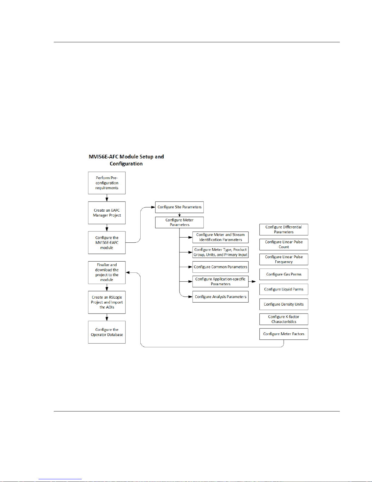
Pre-Configuration Processes
This section describes the pre-configuration process. There are a small number
of tasks to complete before configuring your MVI56E-AFC project.
The following flow illustrates the full configuration process.
ProSoft Technology, Inc. Page 9 of 149
October 2, 2018
Page 10

Before you Begin MVI56E-AFC ♦ Version 4.04
Pre-Configuration Requirements
Before you start to configure the MVI56E-AFC, you must:
Download EAFC Manager software
Download the MVI56E-AFC Add-On Instructions (AOIs)
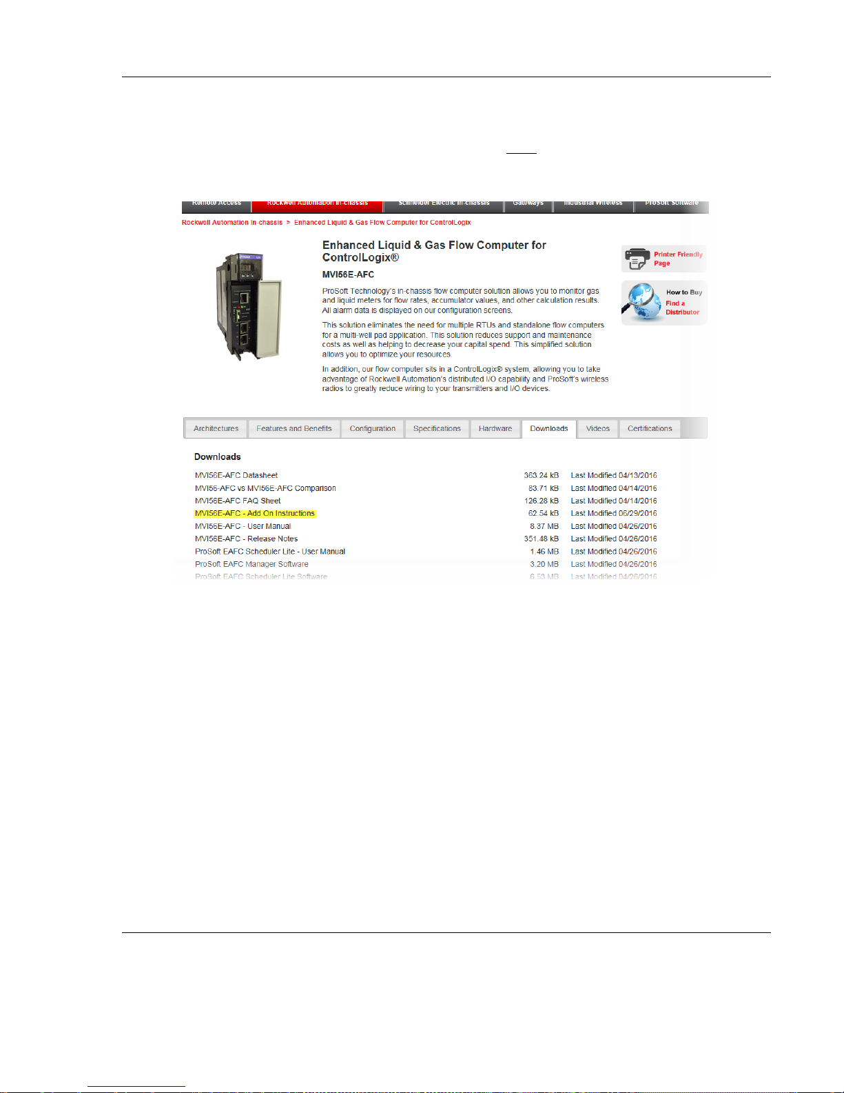
Downloading EAFC Manager
The EAFC Manager can be downloaded from the ProSoft Technology website.
1 Navigate to the MVI56E-AFC webpage found here.
2 Click on the DOWNLOADS tab.
3 Click on the PROSOFT EAFC MANAGER link and follow the prompts to
download and install the application.
Note: Leave this page open. You will also be downloading AOIs from this page as described in the
next section.
Page 10 of 149 ProSoft Technology, Inc.
October 2, 2018
Page 11
MVI56E-AFC ♦ Version 4.04 Before you Begin
Downloading AOIs to your system
1 Navigate to the MVI56E-AFC webpage found here.
2 Click on the DOWNLOADS tab.
3 Select MVI56E-AFC ADD ON INSTRUCTIONS.
The AOIs are downloaded as a zip file.
The zip file contains the Main AOI as well as four additional AOIs that pertain to
your meter application. The four additional AOIs include:
Linear Gas
(MVI56E-AFC_AddOn_Rung_MeterLinearGas_vx_x.L5X)
Linear Liquid
(MVI56E-AFC_AddOn_Rung_MeterLinearLiquid_vx_x.L5X)
Differential Liquid
(MVI56E-(AFC_AddOn_Rung_MeterDifferentialLiquid_vx_x.L5X)
Differential Gas
(MVI56E-AFC_AddOn_Rung_MeterDifferentialGas)vx_x.L5X)
ProSoft Technology, Inc. Page 11 of 149
October 2, 2018
Page 12

Before you Begin MVI56E-AFC ♦ Version 4.04
Meter Type
Configured As (Differential or Linear)
Turbine
Linear
Positive
Displacement
Linear
Magnetic
Linear
Orifice
Differential
V-Cone
Differential. You must configure the meter as V-Cone type in the MVI56E-AFC
Manager (Meter Configuration / Calculation Options)
Wedge
Differential. Refer to Wedge Meter Applications for information about using the
wedge meters.
Vortex
Linear or Differential
Ultrasonic
Linear or Differential
Coriolis
Linear or Differential
Download the Main AOI and the AOI file that pertains to your meter type. For
instance, if the MVI56E-AFC is going to be used for Differential Gas meter runs,
you only need the MVI56E-AFC_MeterDifferentialGas_Vx_x.L5X file.
You will use these files when you set up your RSLogix project later in this guide.
Locating information for your meter type
MVI56E-AFC supports the following meters:
Note: Due to the broad range of meters in the market today, refer to the manufacturer specification
to evaluate the use of the module (even if listed here).
Note: For Vortex, Ultrasonic, or Coriolis meters, the selection depends on the output generated by
the meter.
If the meter provides a pulse train representing the volume increment, the
MVI56E-AFC should be configured as linear with the primary input set to Pulse
Count.
If the meter provides instantaneous flow rate, the MVI56-AFC should be
configured as differential with the primary input set to Flow Rate.
Page 12 of 149 ProSoft Technology, Inc.
October 2, 2018
Page 13

MVI56E-AFC ♦ Version 4.04 Before you Begin
What type of meter
are you
configuring?
What is the primary
output from your flow
meter and associated
instrumentation?
Configure your
meter type as…
Configure your
primary input as…
Orifice Meter
Differential Pressure
Differential
Differential Pres
V-Cone Meter
Differential Pressure
Differential
Differential Pres
Wedge Meter
Differential Pressure
Differential
Differential Pres
Coriolis Meter
Flow Rate
Differential
Flow Rate
Pulse Count and Pulse
Frequency
Linear
Pulse Count
Pulse Frequency Only
Linear
Pulse Frequency
Vortex Meter
Flow Rate
Differential
Flow Rate
Pulse Count and Pulse
Frequency
Linear
Pulse Count
Pulse Frequency Only
Linear
Pulse Frequency
Ultrasonic Meter
Flow Rate
Differential
Flow Rate
Pulse Count and Pulse
Frequency
Linear
Pulse Count
Pulse Frequency Only
Linear
Pulse Frequency
Turbine Meter
Pulse Count and Pulse
Frequency
Linear
Pulse Count
Pulse Frequency
Linear
Pulse Frequency
Pulse Count
Linear
Pulse Count
Positive
Displacement
Same as Turbine
Magnetic
Same as Turbine
To locate configuration information about your meter, refer to the following table:
The following sections provide configuration steps based on:
Meter Type
Primary Meter Output
What’s being measured
Locate the configuration steps for your application and then use the links
provided to jump to the sections of this manual that only apply to you.
ProSoft Technology, Inc. Page 13 of 149
October 2, 2018
Page 14
Before you Begin MVI56E-AFC ♦ Version 4.04
Accumulator
Alarm
Back
Calculate
Calibrate
Calibrate 2
Ethernet
Event
Export
Flow
Gas
Liquid
Login
Logout
Meter
Meter
Network
Delete
Permission
Add
Permission
Edit
Permission
Generic
Permission
Port
Pressure
Prover
Pulse
Delete Role
Add Role
Edit Role
Generic
Role
Serial
Connection
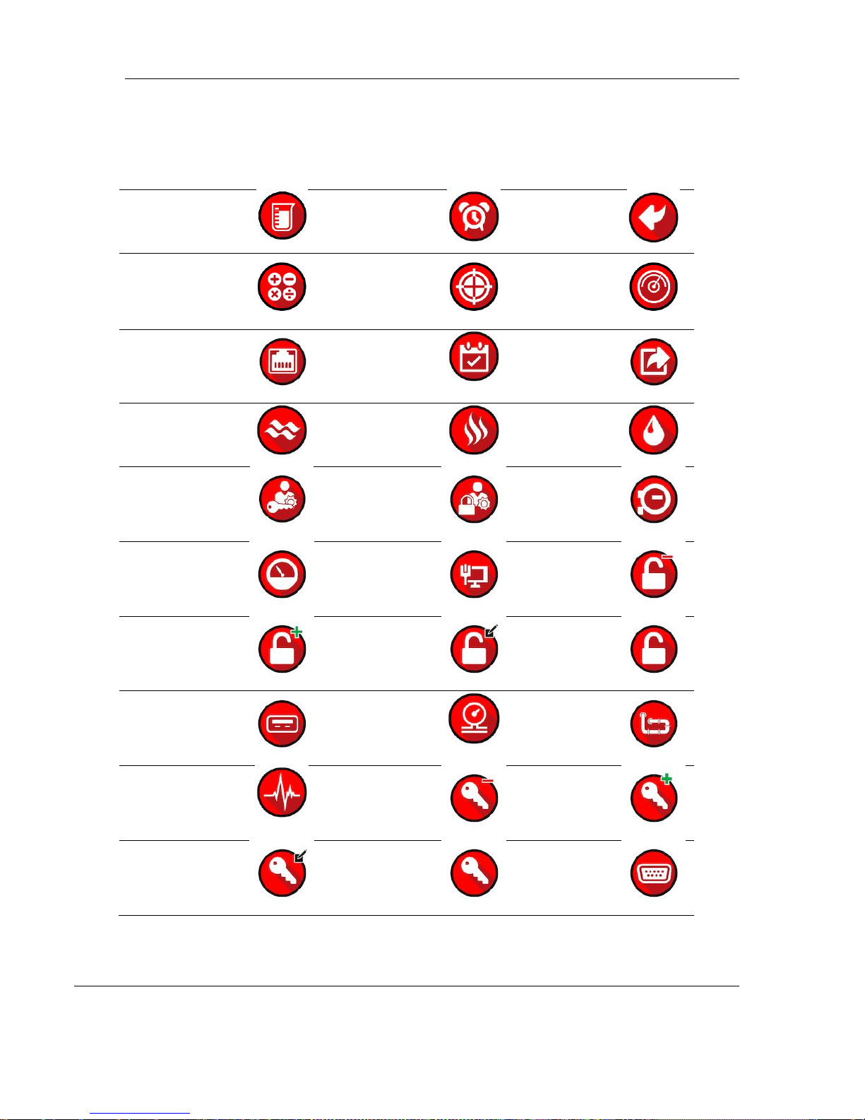
Configuration Aids
This manual contains icons within each section. Each icon represents a
relationship to the topic.
Page 14 of 149 ProSoft Technology, Inc.
October 2, 2018
Page 15

MVI56E-AFC ♦ Version 4.04 Before you Begin
Site
Stream
Temp
User
Delete User
Add User
Edit User
View
Delete
View
Add View
Edit View
Volume
The icons are used as visual cues to provide a hint of the type of information
contained within a section.
ProSoft Technology, Inc. Page 15 of 149
October 2, 2018
Page 16
Before you Begin MVI56E-AFC ♦ Version 4.04
Using the Modbus Dictionary
Important: Although this manual is continuously maintained to bring you the latest information, the
Modbus Dictionary contains the latest information on registers and dictionary sections. It is
recommended that you use the Modbus Dictionary to locate bank and register values to ensure
that you are looking at the latest information.
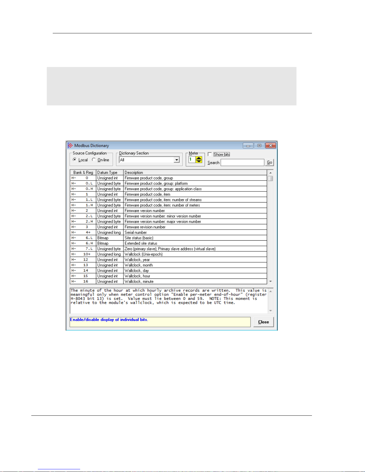
The Modbus dictionary provides a means to locate data anywhere in the module.
The dictionary allows you to select various data types from database regions. It
then displays Modbus bank and register values.
Page 16 of 149 ProSoft Technology, Inc.
October 2, 2018
Page 17
MVI56E-AFC ♦ Version 4.04 Before you Begin
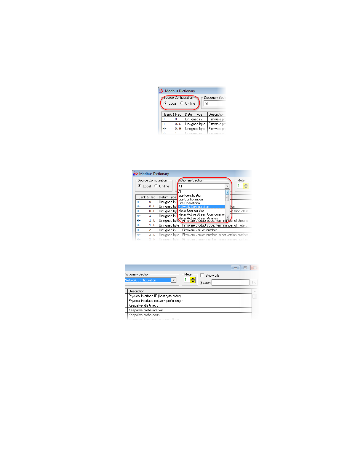
You can use the Modbus Dictionary locally or while EAFC manager is directly
connected to the MVI56E-AFC. From the Source Configuration section, select
LOCAL if you are just running Modbus Dictionary locally or select ON-LINE if
connected to a module.
The Dictionary Section drop-down list allows you to select different types of data
from different sections of the module.
The Meter selection allows you to specify a specific meter in order to view only
information pertaining to the selected meter.
If selected, the SHOW BITS checkbox allows the bits to be displayed in the Bank &
Reg column.
The Search box allows you to search for specific data. The search is applied to
entries in the Description column and is case insensitive.
ProSoft Technology, Inc. Page 17 of 149
October 2, 2018
Page 18
Before you Begin MVI56E-AFC ♦ Version 4.04
Procedure
Ensure that you have a suitable project loaded, especially its version. This
ensures that dictionary items present for your module are available for display.
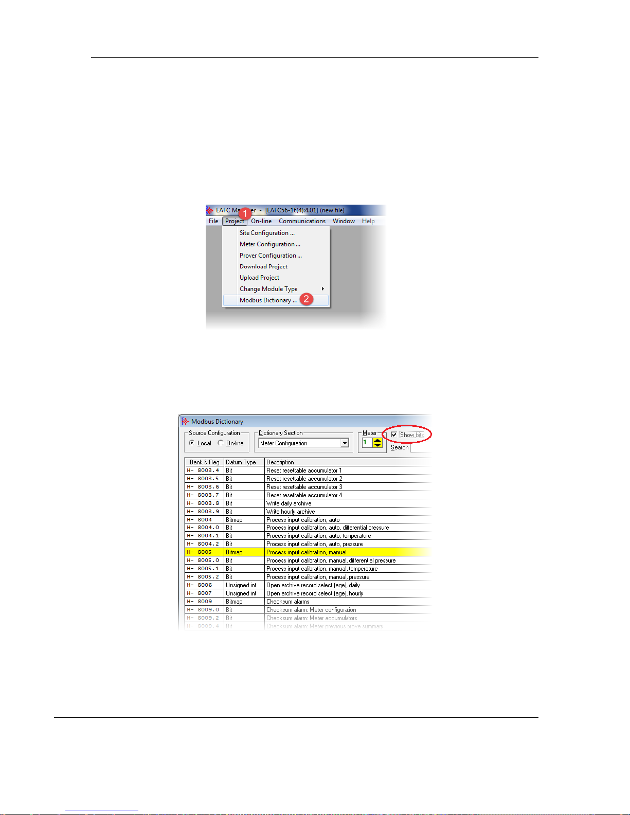
1 In EAFC Manager, select the PROJECT tab.
2 Select Modbus Dictionary, See Starting EAFC Manager for information on
setting your module type.
3 Select the SOURCE CONFIGURATION (Local or On-line).
4 Select the DICTIONARY SECTION from the drop-down list.
5 Select the METER stream.
6 Check the SHOW BITS checkbox to enable the display of individual bits.
Page 18 of 149 ProSoft Technology, Inc.
October 2, 2018
Page 19
MVI56E-AFC ♦ Version 4.04 Before you Begin
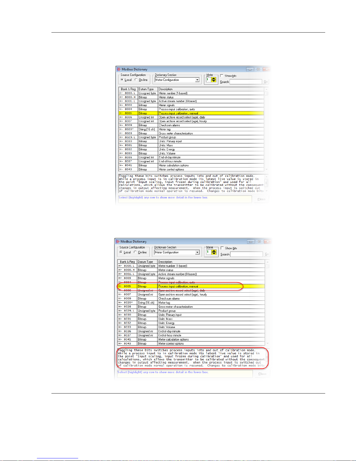
7 Click on the appropriate row.
8 Once a row is selected, additional information is displayed at the bottom of
the window.
ProSoft Technology, Inc. Page 19 of 149
October 2, 2018
Page 20

Before you Begin MVI56E-AFC ♦ Version 4.04
9 Observe the Bank and Reg information in the first column. This column may
contain a number of items with different representations.
In the first row, the first position indicates whether the register is a Holding
Register (H-) or an Input Register (I-), the second position represents the
register (8000). The third position indicates high order bytes (H), low order
bytes (L), multiple registers (*), and a plus sign (+) indicates that there are
two registers (used for 32-bit quantities, i.e., long integer and floating point
elements).
If SHOW BITS is checked, a number in the third position is the bit number. For
Datum Type “String”, each register holds two characters.
Page 20 of 149 ProSoft Technology, Inc.
October 2, 2018
Page 21
MVI56E-AFC ♦ Version 4.04 Creating an EAFC Manager Project
2 Creating an EAFC Manager Project
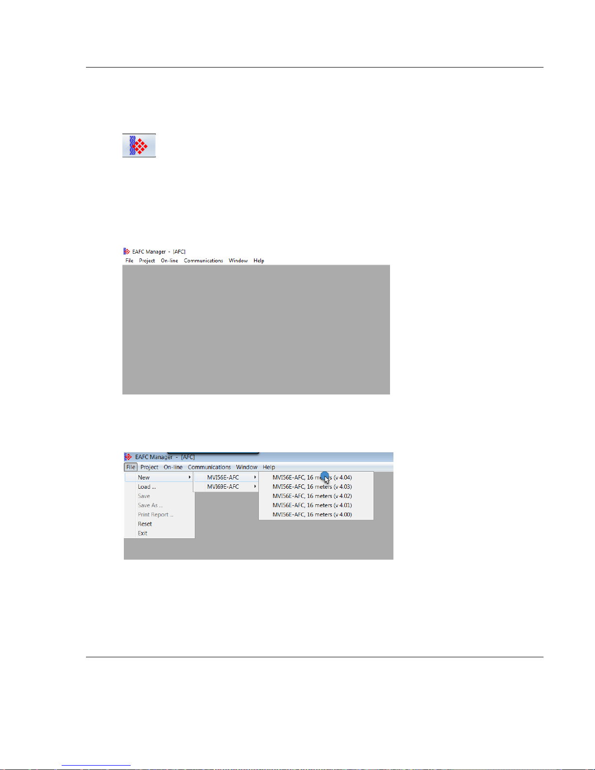
Starting EAFC Manager
1 Click START > PROGRAMS.
2 From the Programs menu, choose PROSOFT TECHNOLOGY.
3 From the ProSoft Technology folder, choose EAFC MANAGER.
The EAFC Manager opens.
4 Select FILE > NEW > MVI56E-AFC > MVI56E-AFC, 16 METERS (VX.XX). The
EAFC Manager project must match the firmware running on the EAFC.
ProSoft Technology, Inc. Page 21 of 149
October 2, 2018
Page 22

Creating an EAFC Manager Project MVI56E-AFC ♦ Version 4.04
Communications between the EAFC Manager and the MVI56E-AFC is not
required during the configuration stage. However, you can establish
communications at this point if you wish. Simply follow the instructions Chapter
19 “Installing the Module in the Rack” and Chapter 20 “Connecting the MVI56E-
AFC Module to the EAFC Manager”.
When you are ready to download the EAFC Manager project to the module, see
Chapter 21 ”Downloading the Project to the Module “. For information on creating
an RSLogix project and importing and using the AOIs, see Chapter 22 “Create
your RSLogix Project and Import the AOIs”.
Page 22 of 149 ProSoft Technology, Inc.
October 2, 2018
Page 23
MVI56E-AFC ♦ Version 4.04 Configuring Site Parameters
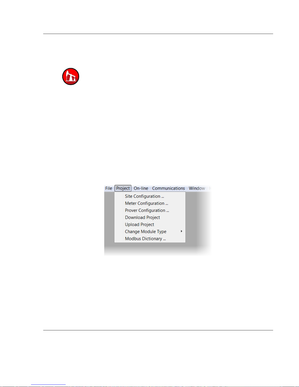
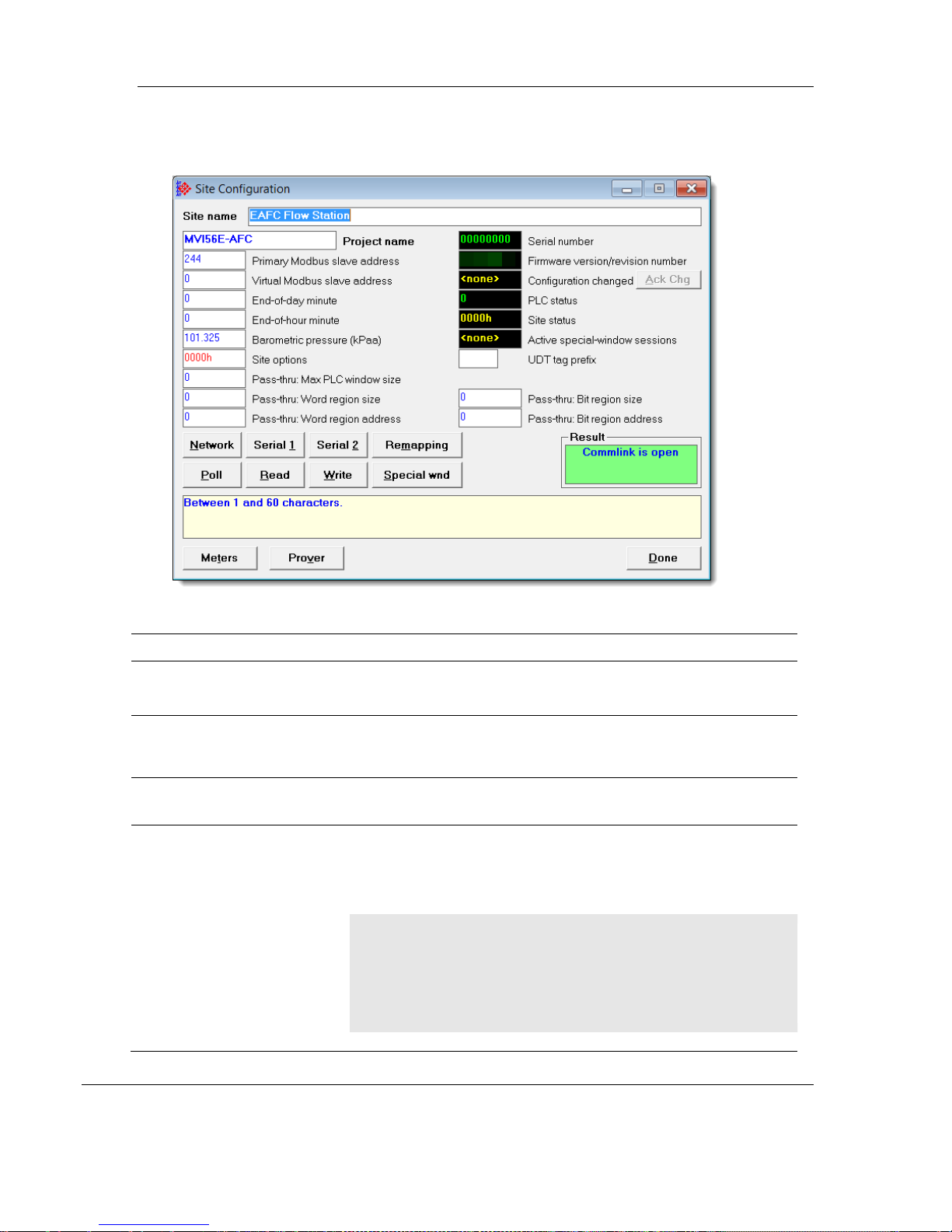
3 Configuring Site Parameters
Configure the overall settings for the site. The Site Configuration dialog box is
where you assign the settings that apply to the entire project.
Project name
Modbus slave addresses
Memory allocation
Port configuration and mapping
Site options and status
You can also obtain the MVI56E-AFC firmware version from this window.
Accessing Site Configuration Parameters
From the Project menu, choose SITE CONFIGURATION.
ProSoft Technology, Inc. Page 23 of 149
October 2, 2018
Page 24
Configuring Site Parameters MVI56E-AFC ♦ Version 4.04
Parameter
Description
Site Name
Enter a site name. This parameter identifies the site (1 to 64
characters). The default is “AFC Flow Station”. Edit this if needed.
Project Name
This parameter allows an external application such as EAFC
Manager to synchronize its database with the database resident in
the module. Default is "MVI56E-AFC".
Primary and Virtual Modbus
Slave Address
If you plan on setting these parameters, please refer to the MVI56E-
AFC Reference Guide for additional details.
End of Day Minute
This parameter sets the minute of the day when the daily archives
are created. The default value of 0 (zero) creates the daily archive at
midnight. Valid values are between 0 and 1439. This moment is
relative to the module’s wallclock, which is expected to be UTC time.
Important: The End of Period (End-of-day minute and End-of-hour
minute) settings are global settings, unless these settings are set by
meter on the Meter Configuration page. If these parameters are set
per meter, and enabled under control options, the options specified
per meter take precedence over the same settings on the Site
Configuration page.
This action opens the Site Configuration dialog box.
Page 24 of 149 ProSoft Technology, Inc.
October 2, 2018
Page 25

MVI56E-AFC ♦ Version 4.04 Configuring Site Parameters
Parameter
Description
End of Hour Minute
This parameter sets the minute of the hour when the hourly archives
are created. The default value of 0 (zero) creates hourly archives at
the top of each hour. Valid values are between 0 and 59. This
moment is relative to the module’s wallclock, which is expected to be
UTC time.
Important: The End of Period (End-of-day minute and End-of-hour
minute) settings are global settings, unless these settings are set by
meter on the Meter Configuration page. If these parameters are set
per meter, and enabled under control options, the options specified
per meter take precedence over the same settings on the Site
Configuration page.
Barometric Pressure
This parameter sets the barometric pressure used on the module
calculations. The module expects each meter's pressure input to be
in gauge units. Because the AGA8, AGA3, and some API2540
calculations require the pressure of the fluid to be in absolute units,
the module adds barometric pressure to the gauge pressure in order
to obtain the absolute pressure.
The calculation assumes that all meters measured by a single
MVI56E-AFC are located at the same site and have the same
barometric pressure.
ProSoft Technology, Inc. Page 25 of 149
October 2, 2018
Page 26

Configuring Site Parameters MVI56E-AFC ♦ Version 4.04
Parameter
Description
Event log lockable
If clear, the event log behaves as a FIFO buffer; a new record
overwrites the old one even if the overwritten event has never
been downloaded, in which case, the event is permanently
lost. If set, and the log is full with never downloaded events,
then the log is locked. Controllable events (changes to most
datum points) are not allowed to occur. Non-critical, noncontrollable events (e.g. checksum alarms) are discarded and
are permanently lost, and critical non-controllable events (e.g.
PLC mode change) are written as usual and the overwritten,
never downloaded events are permanently lost. A locked log
must be downloaded to unlock it for normal behavior.
Barometric pressure in psia
If set, the barometric pressure will be expressed in psia units,
otherwise it will use kPaa.
Configuring Site Options
The Site Options dialog box opens when you click the SITE OPTIONS field in the
Site Configuration dialog box. Not all options are available unless other
parameters and options are selected during the configuration process.
Page 26 of 149 ProSoft Technology, Inc.
October 2, 2018
Page 27
MVI56E-AFC ♦ Version 4.04 Configuring Site Parameters
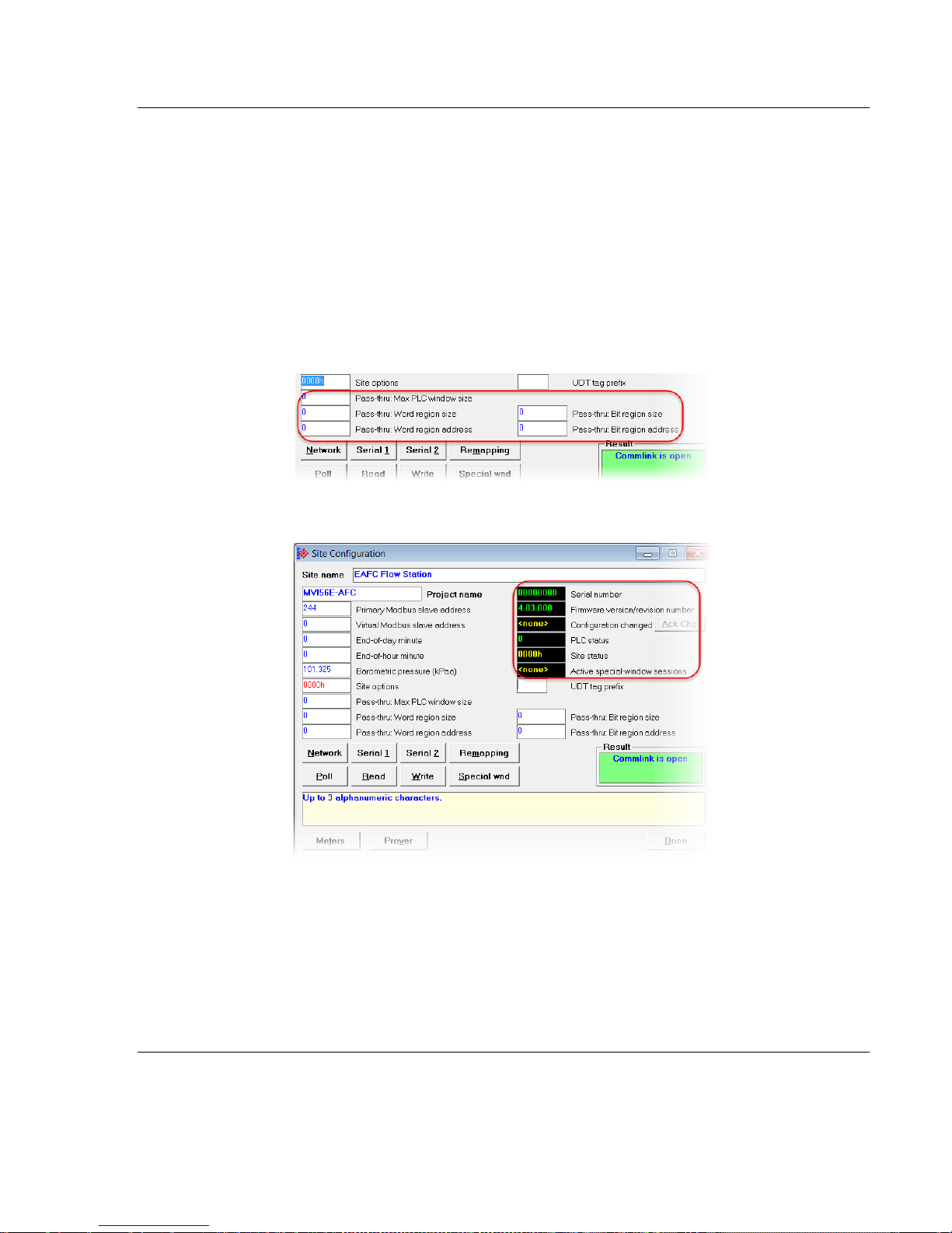
Configuring Pass-thru Options
The Pass-Thru feature can be used for delivering data written by Modbus
packets directly to the PLC logic, bypassing the MVI56E-AFC’s Modbus
database. For details on configuring this option, please refer to the MVI56E-AFC
Reference Guide.
The module supports the Modbus Pass-Thru feature for write commands. When
the pass-thru region in the virtual slave is properly configured, all Modbus write
commands pointing inside that area will be handled by ladder logic using the
Modbus Pass-Thru function block.
Viewing Site Configuration Status
This section of the Site Configuration screen is used to provide Site status
information. Site status features are discussed in the MVI56E-AFC Reference
Guide.
ProSoft Technology, Inc. Page 27 of 149
October 2, 2018
Page 28
Configuring Site Parameters MVI56E-AFC ♦ Version 4.04
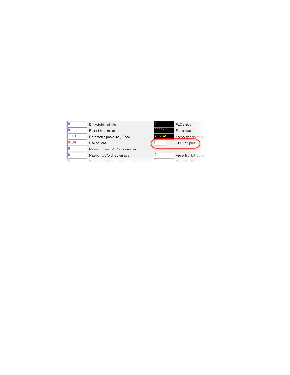
UDT Tag Prefix
Prefix for generated UDT names. UDT definition files generated for the AFC
project, including those for backplane-return layouts and archive record layouts,
may be imported into the RSLogix project. To avoid conflict with names of other
types, tags, and files, especially those generated for other EAFC modules in the
same rack, this optional prefix may be prepended to each generated name (after
the leading “EAFC_”).
If not specified, generated names are not prefixed. If specified, the prefix must be
an alphanumeric string of not more than 3 characters, and it is prepended to
each generated name with an underscore (“_”) separator.
Page 28 of 149 ProSoft Technology, Inc.
October 2, 2018
Page 29

MVI56E-AFC ♦ Version 4.04 Configuring Site Parameters
Exporting UDT Files
You can export UDT files through the Backplane Return window.
Note: The backplane return window exports Backplane Return UDTs. Archive record layout UDTs
are exported from the Archive Configuration Window (after saving the project).
From the Meter Configuration window:
1 Select the meter number.
2 Click on the BACKPLANE RETURN button.
This opens the Backplane-Return Configuration window.
ProSoft Technology, Inc. Page 29 of 149
October 2, 2018
Page 30

Configuring Site Parameters MVI56E-AFC ♦ Version 4.04
3 From the Dictionary section, select the UDT file files. This activates the
INSERT ITEM button.
4 Click the INSERT ITEM button to add the file to the Process Input side of
the page. When UDT files are inserted, the EXPORT UDT button is
activated.
5 Do the same from the Component Analysis tab.
6 When you’ve finished adding the UDT files, click the EXPORT UDT button.
The files are placed in a sub-directory of the directory that contains the
project. The directory is named using the name of the project and
extension .PLC.
Page 30 of 149 ProSoft Technology, Inc.
October 2, 2018
Page 31

MVI56E-AFC ♦ Version 4.04 Configuring Site Parameters
Setting Communication Parameters
ProSoft Technology, Inc. Page 31 of 149
October 2, 2018
Page 32

Configuring Site Parameters MVI56E-AFC ♦ Version 4.04
TCP
Communication
Use to configure Modbus TCP/IP communication
settings.
Serial 1 or Serial 2
Use Serial 1 or Serial 2 buttons to configure serial
communication settings. Use Serial 2 to set up a Modbus
Master.
Page 32 of 149 ProSoft Technology, Inc.
October 2, 2018
Page 33

MVI56E-AFC ♦ Version 4.04 Configuring Site Parameters
Configuring Modbus TCP/IP
You must configure the communication parameters for the Ethernet port using
the EAFC Manager software (Site Configuration):
ProSoft Technology, Inc. Page 33 of 149
October 2, 2018
Page 34

Configuring Site Parameters MVI56E-AFC ♦ Version 4.04
Server Configuration
The Server tabs allow you set different configurations for up to four servers.
Page 34 of 149 ProSoft Technology, Inc.
October 2, 2018
Page 35

MVI56E-AFC ♦ Version 4.04 Configuring Site Parameters
Step
Task
Description/Example
1
Click on the tab
of the server
that you want to
configure.
Enable the
server by
clicking the
Enabled
checkbox.
2
Configure the
network
Interface.
This field indicates the IP address of the physical interface in dotted
decimal format.
The Mask bits indicate the network prefix length of the physical
interface. This is a number between 1 and 31.
TCP port is the Modbus TCP/IP port for the selected server. This the
MBAP listener port, typically 502 (default). You can use a range
between 1024 and 65535.
3
Set up Mode
and AFC Slave
settings
Set the module as an End Device or a Gateway.
The following process applies to each server:
ProSoft Technology, Inc. Page 35 of 149
October 2, 2018
Page 36

Configuring Site Parameters MVI56E-AFC ♦ Version 4.04
Step
Task
Description/Example
If set to an End Device (has its own Modbus database), the unit code
is ignored and is echoed verbatim in the response regardless of its
value.
If set to Gateway (protocol converter between the TCP network on
one end, and a traditional serial Modbus network on the other end),
the serial Modbus network is virtual consisting of the MVI56E-AFC’s
primary and virtual slaves (only), and the unit code must be the
configured slave address of the targeted MVI56E-AFC slave.
4
AFC Slave
The effect of the AFC Slave option depends on Mode setting.
If the device is set as End Device, then this option selects which of
the two MVI56E-AFC slaves is to be the addressed end device.
If the device is set to Gateway, then this option changes to a
checkbox that hides the primary slave. If not selected, both slaves
are addressable, but if set, only the virtual slave is addressable.
In either case, if a command addresses the virtual slave but the
virtual slave does not exist, no response is issued.
AFC slave indicates whether this is a primary or virtual slave.
5
Swap Words
If checked, swaps the Modbus words transferred through this port.
This parameter is only accessible to those data points that hold 32-bit
quantities (long integers, floats, totalizers).
6
Disable passthru
The Modbus Pass-thru feature allows you to configure a Modbus
Pass-Thru region in the Virtual Slave (Project > Site Configuration).
See the MVI56E-AFC Reference Guide for detailed information.
7
Maximum
simultaneous
connections
Set the maximum number of connections for this server. Eight (8)
total connections are available and can be configured as required.
For example, each server might represent a different network. Server
1 might have a single connection while server 2 may have 3, server 3
with 2, and server 4 with 2 for a total of 8.
8
Reserved
connections
A “reserved connection” is one whose resources are always available
for use by this server, whether or not such a connection is currently in
use, so that regardless of activity on other servers, this number of
Page 36 of 149 ProSoft Technology, Inc.
October 2, 2018
Page 37

MVI56E-AFC ♦ Version 4.04 Configuring Site Parameters
Step
Task
Description/Example
connections to this server can always simultaneously exist. This
setting must not exceed the maximum number of connections
permitted for this server if that maximum is non-zero. The total
number of reserved connections over all servers must not exceed the
maximum number of connections permitted overall. Server #1 always
has at least one reserved connection. Range 1 to 8, default 1 with
corresponding for others as 0 to 8..
9
Idle connection
timeout, min.
Specify the number of minutes that a connection may be idle before
being disconnected. A timeout of 0 means no timeout (the connection
may remain idle indefinitely).
Setting Whitelist Options
Whitelist configuration is an ordered sequence of eight entries, each of which
comprises:
An IP range (network IP and mask length)
A boolean "color" flag; white = allow, black = deny.
An entry whose components are all zero (IP 0.0.0.0, prefix length is 0, color is
"white") is empty. It is ignored during application of the whitelist and its position in
the sequence is irrelevant. The relative positioning of non-empty entries is
relevant however, as a later entry can override the effect of an earlier entry.
See the MVI56E-AFC Reference Guide for detailed information.
ProSoft Technology, Inc. Page 37 of 149
October 2, 2018
Page 38

Configuring Site Parameters MVI56E-AFC ♦ Version 4.04
Parameter
Description
Keepalive idle time
This setting enables a network server to free up resources allocated to
broken connections. The three settings are:
Idle time
Probe interval
Probe count
When a connection becomes idle (no requests to the server), it could be
merely because the client has nothing to say or it could be due to a broken
connection. “Keepalive” enables the server to reasonably determine which
and act accordingly.
When a connection has been idle for the “idle time”, the server sends up to
“probe count” probes at the rate of the “probe interval” delay between each.
Advanced Tab
Overall Settings
Page 38 of 149 ProSoft Technology, Inc.
October 2, 2018
Page 39

MVI56E-AFC ♦ Version 4.04 Configuring Site Parameters
Parameter
Description
A “probe” is a TCP/IP packet that asks the client “Are you still there?”. If the
client answers any probe with “Yes, I’m still here”, then the connection is
good. The client is merely silent and the server resets “keepalive” logic for
another cycle.
If the client does not answer any probe, then the server deems the
connection to be broken and closes it to free up its resources for allocation.
Keepalive probe interval
See above.
Keepalive probe count
See above.
Maximum simultaneous
connections
The maximum concurrently active connections over all servers. This should
be a number between 1 and 8. The default is 8.
Complete packet timeout
The timeout for receiving a complete packet. The timeout becomes
effective upon receipt of the first octet of a packet's MBAP header and
imposes a limit on the time that may elapse before receiving the last octet
of that packet. If the timeout expires, the connection is shut down. Valid
range is 1 through 60 with a default of 5 seconds.
Orphaned connection
timeout
This timeout (in minutes) becomes active when a connection is orphaned
by a sufficiently significant change to its parent server’s configuration. This
setting provides a window of time during which the connection remains
alive so that the client can gracefully close it before establishing a
replacement connection according to the network’s updated requirements.
Server changes causing orphanization include (but not limited to):
Disabling the server
Change of IP address
Change to whitelist the disallows the client’s IP
Reduction or removal of access permitted, e.g. primary vs virtual
slave.
Change of protocol; e.g., gateway vs end-device mode, swap
options.
Orphanization of a connection breaks the association between the
connection and its parent server so that the connection no longer belongs
to any server. Server settings in effect prior to orphanization become
frozen for that orphan for the remainder of its limited life. A subsequent
reconfiguration of this or any other server that reestablishes the frozen
settings does not re-associate the connection with the server; the
connection remains orphaned and its timeout remains active.
Upon timeout expiry, the connection is shut down. A timeout of 0 causes
an immediate shutdown. Changing this setting does not adjust timeouts in
effect for already existing orphans.
Valid values: 0 to 60, Default is 0.
ProSoft Technology, Inc. Page 39 of 149
October 2, 2018
Page 40

Configuring Site Parameters MVI56E-AFC ♦ Version 4.04
Parameter
Values
Baud Rate
9600, 19200, 28800, 38400, 57600, 115200, 230400
Data Bits
7 or 8
Stop Bits
1 or 2 Bits
Mode
RTU or ASCII
Parity
None, Even or Odd
Web Interface/Gateway
This IP address and Mask bits pertain to the address of the module itself. This is
not a Modbus TCP/IP address used by the MVI56E-AFC application. The default
web interface address is 192.168.0.250.
Once configured, click READ from the Site page to save changes.
Configuring Serial 1 and Serial 2
The MVI56E-AFC contains two serial port connections. Serial 2 may be used as
a Modbus Master.
Serial Only
The module supports the following communication parameters for each
communication port:
Note: Do not configure a port for both RTU mode and 7 data bits as this combination is not
supported by the Modbus protocol.
Page 40 of 149 ProSoft Technology, Inc.
October 2, 2018
Page 41

MVI56E-AFC ♦ Version 4.04 Configuring Site Parameters
You must configure the communication parameters for each communication port
using the MVI56E-AFC Manager software (Site Configuration):
ProSoft Technology, Inc. Page 41 of 149
October 2, 2018
Page 42

Configuring Site Parameters MVI56E-AFC ♦ Version 4.04
Option
Description
Modbus Master
Enables the Modbus Master for the port (Serial 2). The Modbus Master
command is generated from the processor using ladder logic (Modbus
master block). After the Modbus Master transaction is completed the
module is ready to receive another Modbus Master request from the
ladder logic:
Modbus Slave
MVI-AFC
Processor
Modbus
Master
Block
Modbus
Command
The following Modbus functions are support for Modbus Master operation:
Modbus Function Code
Description
1
Read Coil Status
2
Read Input Status
3
Read Holding Registers
4
Read Input Registers
15
Force (Write) Multiple Coils
16
Preset (Write) Multiple
Registers
The module offers flexibility for Modbus Master operation, allowing ladder
logic to select one of the following data types:
Bit (packed 16 to a word)
Word (16-bit register)
Long (32-bit items as register pairs)
Long Remote (32-bit items as single registers)
Note: Long data type implements each data unit as one pair of 16-bit
registers (words). Each register contains two bytes. Long remote data
type implements each data unit as one 32-bit register. Each register
contains four bytes. The proper choice depends on the remote slave’s
Modbus implementation.
Hide Primary Slave
When checked, protects the Primary Modbus Slave from any read or write
command from a Modbus master device. In this case, you could also
remap the register from the Primary Slave to the Virtual Slave protecting
each register from write commands (refer to the Primary & Virtual Modbus
Port Options
Page 42 of 149 ProSoft Technology, Inc.
October 2, 2018
Page 43

MVI56E-AFC ♦ Version 4.04 Configuring Site Parameters
Option
Description
Slaves Configuration section).
Swap Modbus Words
If checked, the words transferred by a Modbus master device will be
swapped. This setting only applies to double-register data items (floating
point and long integer).
Disable Pass-thru
The Modbus pass-through feature allows you to configure a Modbus
Pass-through region in the virtual slave (Project > Site Configuration).
After the module receives a holding register write command (Modbus
functions 6 or 16) or a bit write command (Modbus functions 5 or 15), it
generates a pass-through block to be sent to the processor containing the
Modbus command data. You can define a word pass-through region for
words or bits.
Note: You must enable the Virtual Slave by configuring a Modbus
address greater than 0 (Project > Site Configuration).
You can control which communication parts will support the pass-through
(Project > Site Configuration > Port X button).
This feature requires ladder logic to read the pass-through block from the
module to the processor. Refer to the Ladder Logic section in the
MVI56E-AFC Reference Guide for more information about the passthrough feature.
ProSoft Technology, Inc. Page 43 of 149
October 2, 2018
Page 44

Configuring Site Parameters MVI56E-AFC ♦ Version 4.04
Poll Button
The function of the POLL button is to update the display of site status (the blackbackground boxes in the upper right quadrant of Site Configuration).
Local Port Settings Dialog Box
This dialog is displayed whenever menu item Communications/Local Port
Settings is clicked, or any other action that requires a connection to the module is
invoked while such a connection is not yet present. Such “other actions” include
the READ, WRITE, and POLL buttons of the Site Configuration pane, but also
numerous other actions such a Read and Write of Meter Configuration, menu
item Project/Download Project, and menu item Communications/Login Module.
If a connection is already present, this dialog is not automatically displayed upon
any “other action” but only upon the Local Port Settings menu item. Similarly, if
the connection exists but the operator has not logged in, while the “other action”
requires login, the Login Module window is automatically displayed.
Both conditions are cascaded. For example, a Read when not connected
displays first the Local Port Settings window to connect and then the Login
Module window to log in.
Adjust the communication settings if necessary. Click CONNECT to save the
settings and OK to connect.
Page 44 of 149 ProSoft Technology, Inc.
October 2, 2018
Page 45

MVI56E-AFC ♦ Version 4.04 Configuring Site Parameters
Read Button
The READ button reads the current site configuration from the module to the local
PC. Look at the result area (green rectangle) on the Site Configuration dialog box
for the status of the read operation. When a "Success" indication shows in the
result area, it indicates that the site configuration has been successfully read to
the local PC.
Write Button
After you have completed the site configuration on the local PC EAFC Manager
software, click the WRITE button to transfer the configuration to the module.
When the Result area shows "Success", the site configuration has been
successfully written to the module.
Click the READ button to read the current module site configuration. The
configuration should match the last write operation data.
If the result area shows "Time out", verify the network connections.
Special Wnd Button
This button displays the Special Windows dialog.
This dialog allows you to set times in minutes or seconds. The times represent
times of no activity. For example, if you set Event log download to 60 seconds,
and no download activity has occurred within that time period, the Event Log
activity is abandoned and no data is logged or committed. The same holds true
for the alarm log, transmitter calibration, and Enron access. You must enter the
ProSoft Technology, Inc. Page 45 of 149
October 2, 2018
Page 46

Configuring Site Parameters MVI56E-AFC ♦ Version 4.04
time interval and optionally the Virtual Slave location of the data. When you are
satisfied with your settings, click DONE. You can come back at any time and
change your settings.
If you want to access these special windows via the virtual slave, assign an
address in the virtual slave to the special window in the Virtual slave location
column. If the Virtual slave location is set to “0”, the special window is unavailable
in the virtual slave.
Done Button
This button stores your settings temporarily and closes the Site Configuration
dialog box. Note that you must also save your project before closing EAFC
Manager, otherwise your configuration will be discarded.
Remapping Button
Refer to the MVI56E-AFC Reference Guide.
Accessing the Data
Information on accessing data is discussed in the MVI56E-AFC Reference
Guide.
Site Status
Site status information is discussed in the MVI56E-AFC Reference Guide.
Page 46 of 149 ProSoft Technology, Inc.
October 2, 2018
Page 47

MVI56E-AFC ♦ Version 4.04 Configuring Meter Parameters
4 Configuring Meter Parameters
Prerequisites
Ensure that all site information is configured as described in the previous
chapters.
What Parameters Do I Have to Configure?
The Meter Configuration page allows you to configure your meter based on your
application. Parameters on this page are based on information that you initially
provide to EAFC Manager.
Configuring a Meter consists of the following steps:
1. Configure Meter Type, Product Group, Units, and Primary Input
2. Configure Meter Identification and Stream Identification Parameters
3. Configure Common Parameters
4. Configure Application-specific Parameters
5. Configure Analysis Parameters
ProSoft Technology, Inc. Page 47 of 149
October 2, 2018
Page 48

Configuring Meter Parameters MVI56E-AFC ♦ Version 4.04
Configuring Meter and Stream Identification Parameters
Identification Parameters identify the meter.
1 Select the Meter number.
2 Click the IDENTIFICATION button to display the Meter Identification window.
Page 48 of 149 ProSoft Technology, Inc.
October 2, 2018
Page 49

MVI56E-AFC ♦ Version 4.04 Configuring Meter Parameters
3 Add the following identifying parameters:
General Type
Manufacturer
Model
Serial Number
Size
Nominal K Factor
4 Click OK when you are done. Repeat this for every configured meter.
Setting End of Period Parameters
These parameters set the End-of-day minute and End-of-hour minute.
End-of-Day Minute
This parameter sets the minute of the day when the daily archives are created.
The default value of 0 (zero) creates the daily archive at midnight. Valid values
are between 0 and 1439.
End-of-hour minute
This parameter sets the minute of the hour when the hourly archives are created.
The default value of 0 (zero) creates hourly archives at the top of each hour.
Valid values are between 0 and 59.
ProSoft Technology, Inc. Page 49 of 149
October 2, 2018
Page 50

Configuring Meter Parameters MVI56E-AFC ♦ Version 4.04
Setting Precedence
You can set the End-of-day minute and End-of-hour minute on the Site page as
well. The parameters set on the site page represent a global setting and End of
Period parameters set on the Meter Configuration are ignored. However, you can
give the Meter setting precedence using the Meter Control Options dialog.
1 Click on the CONTROL OPTS button.
2 Click on the Enable per meter end-of-day and Enable per meter end-of-
hour check boxes.
3 Click DONE.
The settings in the End of Period section for the meter now take precedence over
those set on the Site page.
Page 50 of 149 ProSoft Technology, Inc.
October 2, 2018
Page 51

MVI56E-AFC ♦ Version 4.04 Configuring Meter Parameters
Sample rate alarming – This is the longest period that can elapse between
successive fresh samples of process input values without raising the “sample
rate too low” alarm. This value is specified in seconds with a range of 0 through
30. Zero “0” means that the sample rate test is not performed and alarms are not
raised. The complete implementation requires supporting logic in the PLC. The
default for gas product is 1 second and for any liquid product is 5 seconds.
Setting a Stream Name
To set a Stream Name, click on the IDENTIFICATION button under the Stream
Enabled indicator.
Enter a product description and click OK.
ProSoft Technology, Inc. Page 51 of 149
October 2, 2018
Page 52

Configuring Meter Parameters MVI56E-AFC ♦ Version 4.04
Configuring Meter Type, Product Group, Units, and Primary Input
These parameters must be configured before you configure any common or
application detail parameters. What you select here affects the available
parameters that must be configured for your application.
EAFC Manager needs these parameters in order to hide or show parameters that
pertain specifically to your meter and its primary output based on your meter and
associated instrumentation.
For example, a meter that measures the flow of Crude oils requires that specific
parameters be provided that may not be required of a meter that measures the
flow of gas.
Parameters available to you are determined by these selections.
Based on the previous examples, you essentially have to answer 3 questions
before you begin meter configuration:
1. What kind of meter are you configuring?
2. What is the primary output from your flow meter and associated
instrumentation?
3. What are you measuring (Gas or Liquid)?
Page 52 of 149 ProSoft Technology, Inc.
October 2, 2018
Page 53

MVI56E-AFC ♦ Version 4.04 Configuring Meter Parameters
Column 1
Column 2
Column 3
Column 4
What kind of meter
are you configuring?
What is the primary
output from your flow
meter and associated
instrumentation?
Configure your meter
type as…
Configure your
primary input as…
Orifice Meter
Differential Pressure
Differential
Differential Pres
V-Cone Meter
Differential Pressure
Differential
Differential Pres
Wedge Meter
Differential Pressure
Differential
Differential Pres
Coriolis Meter
Flow Rate
Differential
Flow Rate
Pulse Count and
Pulse Frequency
Linear
Pulse Count
Pulse Frequency Only
Linear
Pulse Frequency
Vortex Meter
Flow Rate
Differential
Flow Rate
Pulse Count and
Pulse Frequency
Linear
Pulse Count
Pulse Frequency Only
Linear
Pulse Frequency
Ultrasonic Meter
Flow Rate
Differential
Flow Rate
Pulse Count and
Pulse Frequency
Linear
Pulse Count
Pulse Frequency Only
Linear
Pulse Frequency
Selecting and Configuring Meter Type, Product Group, Units and Primary
Input Parameters
The following table helps you determine what Meter Type and Primary Input
parameters must be entered in EAFC Manager based on the kind of meter you
are configuring and the primary output of the meter and associated
instrumentation.
To use the following table:
1. Locate the type of meter you are using from Column 1.
2. Determine the primary output of your meter and associated
instrumentation from Column 2.
3. Note your Meter Type from Column 3.
4. Note your Primary Input from Column 4.
You will use the information from Columns 3 and 4 to select your first two
parameters in EAFC Manager.
ProSoft Technology, Inc. Page 53 of 149
October 2, 2018
Page 54

Configuring Meter Parameters MVI56E-AFC ♦ Version 4.04
Column 1
Column 2
Column 3
Column 4
Turbine Meter
Pulse Count and
Pulse Frequency
Linear
Pulse Count
Pulse Frequency
Linear
Pulse Frequency
Pulse Count
Linear
Pulse Count
Positive Displacement
Same as Turbine
Magnetic
Same as Turbine
Columns 3 and 4 of this table have a direct relationship with the Meter
Configuration page of EAFC Manager.
For example, if you are configuring a Coriolis Meter with a primary output of
Pulse Count and Pulse Frequency, your settings in EAFC Manager for Meter
Type and Primary Input would be Linear and Pulse Count as shown in the
following example.
It is important to note that the settings selected within the Meter Type, Product
Group and Units section of the page, determine what configuration parameters
are viewable on the EAFC Manager Meter Configuration page.
Once you’ve selected the correct Meter Type and Primary Input settings based
on the table, you can select the Product Group, and System of Units.
Page 54 of 149 ProSoft Technology, Inc.
October 2, 2018
Page 55

MVI56E-AFC ♦ Version 4.04 Configuring Meter Parameters
Product Group
The Product Group represents what you are measuring (i.e., gas or liquid). The
Product Group drop-down list allows you to select the appropriate Product Group
for your application. Refer to the MVI56E-AFC Reference Guide for detailed
information.
Note: The Product Injected Meter Type feature produces an Accumulation Overflow error. The
associated flow calculations will be invalid.
System of Units
System of Units pertains to how measurements are displayed and are used for
calculations.
US – Temperature in °F, Pressure in psi, Differential Pressure in
hw@60°F.
SI – Temperature in °C, Pressure and Differential Pressure in kPa.
Once these parameters are configured, the parameters that you see on EAFC
Manager are those that apply to your application. That is, what you see on the
MVI56E-AFC Manager page is dependent on these parameter configuration
settings.
Troubleshooting Tip: If the EAFC Manager displays an "Illegal Data Value" message, it typically
indicates an invalid meter type or product group configuration. The module does not accept a
configuration file that attempts to change a meter type or product group for a meter that is currently
enabled. Disable all meters, change the meter types and product groups, and then enable the
meters again.
ProSoft Technology, Inc. Page 55 of 149
October 2, 2018
Page 56

Page 57

MVI56E-AFC ♦ v4.04 Common Parameters
5 Configuring Common Parameters
Common parameters are common to all applications. These parameters are
always visible and should be configured.
ProSoft Technology, Inc. Page 57 of 149
October 2, 2018
Page 58

Common Parameters MVI56E-AFC ♦ Version 4.04
Common parameters include:
Physical Device
Reference Conditions
Accumulators and Flow Rates
Process Input
Control Options
Backplane Return
Calculation Options
Resettable Accumulators
Meter Factors
Stream Options
Selecting the Physical Device
Select your device from the drop-down list. Selects here change calculation
methods based on the meter.
Page 58 of 149 ProSoft Technology, Inc.
October 2, 2018
Page 59

MVI56E-AFC ♦ Version 4.04 Common Parameters
If you are using a differential gas type meter, measuring differential pressure, you
have the option of selecting from the following standards:
Orifice plate (AGA 3 [2012])
Orifice plate (AGA 3 [1992])
Orifice plate (ISO 5167-2)
Nozzle, ISA 1932 (ISO 5167-3 type 1)
Nozzle, long radius (ISO 5167-3 type 2)
Nozzle, Venturi (ISO 5167-3 type 3)
Venturi tube, cast (ISO 5167-4 type 1)
Venturi tube, machined (ISO 5167-4 type 2)
Venturi tube, rough (ISO 5167-4 type 3)
V-cone [Rev 3.2]
V-cone [Rev 2.5]
Wafer-cone
Wedge
The options in the drop-down list change depending on your selections to meter
types. For example, if you select a Linear device type, the following physical
device types are available:
ProSoft Technology, Inc. Page 59 of 149
October 2, 2018
Page 60

Common Parameters MVI56E-AFC ♦ Version 4.04
Specifying Reference Temperature and Pressure (Reference
Conditions)
Measurements of gas and liquids are calculated based on their characteristics at
a specific temperature and atmospheric pressure. Specify the reference
conditions in this area. The default values are 15°C/101.325 kPaa (SI) and
60°F/14.696psia (US), which are the standard API base conditions. If configured
reference conditions are different from API base, the API calculations are done
twice as necessary to correct from flowing conditions to API base and then decorrect from API base to your selected reference.
Page 60 of 149 ProSoft Technology, Inc.
October 2, 2018
Page 61

MVI56E-AFC ♦ Version 4.04 Common Parameters
Setting Accumulators and Flow Rates
Flow Rate Period Unit
Click on the FLOW RATE PERIOD UNIT box to change the flow rate period.
Flow Rate Unit
Click on the FLOW RATE UNIT box to change the flow rate unit.
ProSoft Technology, Inc. Page 61 of 149
October 2, 2018
Page 62

Common Parameters MVI56E-AFC ♦ Version 4.04
Accumulation Unit
Click on the ACCUMULATOR UNIT box to change volume accumulator units.
Accumulator Rollover
This is the value when mass accumulators are reset to zero and it 1 greater than
the highest value that the accumulator may hold.
A value of 1000000 specifies a 6-digit accumulator that rolls over to 0 from
999999. Any unsigned 32-bit value may be entered. A value of 0 indicates a freerunning accumulator, which rolls over to 0 from 4294967295. The default value is
100000000 (8 zeros).
Page 62 of 149 ProSoft Technology, Inc.
October 2, 2018
Page 63

MVI56E-AFC ♦ Version 4.04 Common Parameters
Product Group
Input Variables
Gas
Temperature, Pressure, Flow Rate, Differential Pressure, Pulse Frequency
Liquid
Temperature, Pressure, Flow Rate, Differential Pressure, Pulse Frequency,
Density, Water Content
Configuring Process Input Scaling
Click the PROCESS INPUT button to configure the valid input ranges. If input data
is not within the configured range, the MVI56E-AFC will flag an alarm on the
Meter Monitor dialog box (refer to Meter Monitor section) and the alarm bit for the
meter is set.
The entries available on this dialog box depend on the selected product group,
device, and primary input:
Zero Scale
This value is the minimum valid value for the input variable.
Full Scale
This value is the maximum valid value for the input variable.
ProSoft Technology, Inc. Page 63 of 149
October 2, 2018
Page 64

Common Parameters MVI56E-AFC ♦ Version 4.04
Enabling/Disabling the Meter (Control Opts)
When this option is selected, the meter will begin processing calculations. You
must disable the meter by unchecking this box before you can change the meter
type or product group. You should also disable any meter that is not being used
to allow for best possible module performance. After enabling or disabling the
meter, click DONE, and then click the WRITE button in the Meter Configuration
area. To retrieve the status of a meter, click the READ button in the Meter
Configuration area.
Note: The meter can also be enabled or disabled from ladder logic (refer to the MVI56E-AFC
Setup and Configuration Guide).
Backplane Return
There is at least one backplane function block that is repeatedly and frequently
delivered from the processor (PLC) to the module. This is the block delivers
process inputs used for measurement.
Process Inputs
The backplane transfer protocol specifies that each function block output by the
PLC to the module must elicit a corresponding input function block at the same
location in the overblock with the same size. This returned block contains no data
(contents are all zero).
In order to make use of the empty function block, functionality was developed to
increase efficiency. The normally empty function block from the module to the
PLC now contains selected values that would likely be required by the PLC
program on a regular basis. This is done by mapping slots in the input function
block to points in the Modbus address space. This process is known as
Backplane Return.
Component Analysis Function Block
Another function block that delivers a new component analysis for a gas stream
is similar. When required, it is delivered regularly and although output contents
are relevant, there are no matching input contents that are meaningful for such
an analysis.
The default configuration in the GUI shows the database points that were preselected from the process input return and the empty mapping for the analysis
return.
Page 64 of 149 ProSoft Technology, Inc.
October 2, 2018
Page 65

MVI56E-AFC ♦ Version 4.04 Common Parameters
This provides the user with full functionality for the configuration of both
backplane return blocks.
The user is allowed to select desired values from the Modbus database which
the module delivers to the PLC automatically and on a regular basis without
having to create and issue a separate backplane transaction such as Modbus
Gateway in order to retrieve those values.
The user has the responsibility to re-trigger the analysis function block when the
previous one has completed. This makes the behavior semi-automatic (in
contrast to Process Input behavior which is fully automatic.
Using the Window
Move files from the Dictionary side of the page to the Process Input or
Component Analysis tabs.
1 Select the file.
2 Click on the Process Input or Component Analysis tabs.
3 Click the INSERT ITEM button.
4 Use the MOVE UP or MOVE DOWN buttons to move the file up or down in
the list.
5 Click OK.
If you are moving UDT files, move them from the Dictionary to the Process Input
tab as described for any files.
Click the UDT EXPORT button to export the UDT files.
ProSoft Technology, Inc. Page 65 of 149
October 2, 2018
Page 66

Common Parameters MVI56E-AFC ♦ Version 4.04
Configuring Calculation Options
Click on the CALCULATION OPTS button to access the Meter Calculations Options
dialog. Details on each option can be found in the Modbus Dictionary.
Options that to not apply to the current application are grayed out. See
Calculations Options in the MVI56E-AFC Reference Guide for detailed
information.
Page 66 of 149 ProSoft Technology, Inc.
October 2, 2018
Page 67

MVI56E-AFC ♦ Version 4.04 Common Parameters
Configuring Resettable Accumulators
The MVI56E-AFC supports a total of 12 accumulators per meter channel, divided
into the following categories:
Non-Resettable Accumulators (6)
Resettable Accumulators (4)
Archive Accumulators (2)
Click the RESETTABLE ACCUM button.
The accumulator types are independent. For example, resetting a resettable
accumulator does not affect the other accumulators.
For multiple-stream firmware, each stream also has a set of ten accumulators
(six non-resettable, and four resettable). Increments are applied both to the
meter accumulators and to the accumulators for the active stream.
ProSoft Technology, Inc. Page 67 of 149
October 2, 2018
Page 68

Common Parameters MVI56E-AFC ♦ Version 4.04
Non-Resettable Accumulators
The non-resettable accumulators are only reset when the accumulator rollover
value is reached. The accumulator rollover value, and the accumulator unit must
be configured using the EAFC Manager.
The module supports six non-resettable accumulators in order to show the
measure quantity to be totalized.
Non-resettable accumulator mass
Non-resettable accumulator energy (Gas applications)
Non-resettable accumulator net
Non-resettable accumulator gross
Non-resettable accumulator gross standard (Liquid apps only). For Oil-
water emulsion, this is a non-resettable accumulator for gross clean oil.
Non-resettable accumulator water (Liquid apps only)
Refer to the Modbus Dictionary in EAFC Manager for more information about the
Modbus addresses for these registers.
Page 68 of 149 ProSoft Technology, Inc.
October 2, 2018
Page 69

MVI56E-AFC ♦ Version 4.04 Common Parameters
Resettable Accumulators
From the Resettable Accumulator Select window, click OPTIONS.
The resettable accumulators are referred to as:
Resettable Accumulator 1
Resettable Accumulator 2
Resettable Accumulator 3
Resettable Accumulator 4
Resettable Accumulators are configured from the Resettable Accumulator Select
dialog box. To open this dialog box, click the RESETTABLE ACCUM button on the
Meter Configuration dialog box.
ProSoft Technology, Inc. Page 69 of 149
October 2, 2018
Page 70

Common Parameters MVI56E-AFC ♦ Version 4.04
Accumulator
Modbus address for accumulator
select (Meter-relative)
Default Value
Resettable accumulator 1
126
Net (code 3)
Resettable accumulator 2
127
Gross (code 4)
Resettable accumulator 3
128
Gross Standard (code 5)
Resettable accumulator 4
129
Mass (code 1)
Code
Quantity
0
None
1
Mass
2
Energy (Gas Only)
3
Net
4
Gross
5
Gross Standard (Liquid Only)
6
Water (Liquid Applications Only)
Each Resettable Accumulator can be configured to represent a different quantity
as follows:
Valid Configuration Codes
The valid codes are:
For example, moving a value of 4 to holding register 8126 will configure Meter 1’s
resettable accumulator 1 as "Gross Volume". Moving "0" to holding register 9128
configures Meter 2’s Resettable Accumulator 3 to accumulate nothing (takes it
out of service).
Page 70 of 149 ProSoft Technology, Inc.
October 2, 2018
Page 71

MVI56E-AFC ♦ Version 4.04 Common Parameters
The resettable accumulators are reset when one of the following situations occur.
Resetting from EAFC Manager
You may reset any of the resettable accumulators using the EAFC Manager
(Meter Monitor):
Resetting from Ladder Logic
The ladder logic may send a meter signals block to command one or more
resettable accumulators to be reset. This feature is especially important for
applications involving field installations that require shipping and/or receiving
product batches of predetermined size. Refer to the Ladder Logic section for your
module type for more information.
ProSoft Technology, Inc. Page 71 of 149
October 2, 2018
Page 72

Common Parameters MVI56E-AFC ♦ Version 4.04
Resetting upon Archive Period End or Reset upon Event
Use EAFC Manager to configure the resettable accumulator to be reset when the
archive period ends or when an event occurs. Refer to Event Log in the MVI56EAFC Reference Guide for more information on configuring and monitoring
events.
Resetting when the Accumulator Rollover Value is reached
The resettable accumulator is reset when the accumulator rollover value is
reached. You must configure the accumulator rollover value using the MVI56EAFC Manager software (Meter Configuration).
Resetting a resettable accumulator resets that accumulator for both the meter
and for all its streams.
Page 72 of 149 ProSoft Technology, Inc.
October 2, 2018
Page 73

MVI56E-AFC ♦ Version 4.04 Common Parameters
Archive Accumulators
The archive accumulators are part of the current archive (archive 0) data. These
accumulators are automatically reset when a new archive is generated. Refer to
the Modbus Dictionary – Meter Accumulator section.
You may configure the accumulator quantity to be used for each archive
accumulator using the EAFC Manager (METER CONFIGURATION > ARCHIVE
CONFIG > ACCUMULATOR SELECT):
ProSoft Technology, Inc. Page 73 of 149
October 2, 2018
Page 74

Common Parameters MVI56E-AFC ♦ Version 4.04
Converts to Reference
Temperature and Pressure
Gross Accumulator Net Accumulator
Converts to Reference
Temperature and Pressure
Subtracts Water
Gross Accumulator
Gross Standard
Accumulator
Net Accumulator
Water
Converts to Reference
Temperature and Pressure
Gross Accumulator
Gross Clean Oil
Accumulator
Net Accumulator
Subtracts Water
Water
Net Accumulator Calculation
The Net Accumulator Calculation depends on the product group (gas or liquid).
For gas applications, the Net Accumulator is calculated as follows:
For liquid applications (all except Emulsion), the Net Accumulator is calculated as
follows:
For liquid applications (Oil-Water Emulsion), the net accumulator is calculated as
follows, using API ch 20.1:
Page 74 of 149 ProSoft Technology, Inc.
October 2, 2018
Page 75

MVI56E-AFC ♦ Version 4.04 Common Parameters
Accumulator Totalizer and Residue
The accumulators are expressed as the totalizer and residue parts. This
implementation allows the accumulation of a wide range of increments, while
keeping a high precision of fractional part with an approximately constant and
small round off error.
The totalizer stores the integral part of an accumulator as a 32-bit unsigned
integer. The residue is the fractional part (always less than 1.0) expressed as a
32-bit IEEE floating point.
The Total Accumulator value is given by the formula:
ACCUMULATOR = TOTALIZER + RESIDUE
Example
If the meter monitor window shows the following values for the accumulators:
The total resettable accumulator 1 value (net) is 12.8031153.
Meter Factors
See Configuring Meter Factors.
ProSoft Technology, Inc. Page 75 of 149
October 2, 2018
Page 76

Common Parameters MVI56E-AFC ♦ Version 4.04
Alarming
Action
Alarming: require
manual
acknowledge
If set, then any alarm appearing in the Meter Alarms, registers (I-30 through I-
37) must be manually acknowledged by writing a “1” bit to the corresponding
bit in the “Acknowledgement Required” registers (meter relative), subject to
further constraints configured by the other three “Alarming” meter control
options (this register, bits 1, 2, and 3). If clear, then any alarm is deemed to
be automatically acknowledged at the moment that it occurs: the
“Acknowledgement required” bit is never raised, so no “Alarm
Acknowledged” record is written to the Alarm Log., and the following three
meter control options have no effect. For more information, see the other
three “Alarming” meter control alarms, the “Acknowledgement required”
registers and the “Meter alarms” registers themselves.
Alarming: Disallow
pre-acknowledge
If set, then the acknowledgement of any alarm requires the alarm condition to
have been resolved and its corresponding bit in the "Meter alarms" registers
to be clear. If clear, then alarm acknowledgement may be performed at any
time after the "Acknowledgement required" bit has been raised, even if the
alarm condition itself has not yet been resolved and the alarm bit is still set; in
this case, the continuing presence of the alarm condition does not cause the
"Acknowledgement required" bit to be re-raised, but after the alarm condition
has been resolved (and its alarm bit cleared) a recurrence of the alarm will
again raise the "Acknowledgement required" bit. If meter control option
"Require manual acknowledge" is clear (this register bit 0), then this option is
deemed to be clear and has no effect. For more information, see the other
three "Alarming" meter control options (this register, bits 0, 2, and 3), the
"Acknowledgement required" registers (meter relative), and the "Meter
alarms" registers (meter relative).
Meter Alarm Control Options
Click CONTROL OPTIONS from the Meter Configuration page.
Bits 0 through 4 allow you to set up alarm configurations.
Page 76 of 149 ProSoft Technology, Inc.
October 2, 2018
Page 77

MVI56E-AFC ♦ Version 4.04 Common Parameters
Alarming
Action
Alarming:
Acknowledge
action is sealable
If set, then the acknowledgement of any alarm requires that the Weights &
Measures switch be in the "unlocked" position. If clear, then alarm
acknowledgement requires only that the acknowledging operator have the
necessary permission ("Troubleshooting", permission bit 13). If meter control
option "Require manual
acknowledge" is clear (this register bit 0), then this option is deemed to be
clear and has no effect. For more information, see the other three "Alarming"
meter control options (this register, bits 0, 1, and 3), the "Acknowledgement
required" registers (meter relative), and the "Meter alarms" registers (meter
relative).
Alarming: Must
Ack to resume
normal
measurement
If set, then any divergent measurement behavior that occurs consequent to
an alarm (e.g. value subsitution, separate accumulation) persists until both
the alarm condition has disappeared and the alarm has been acknowledged,
at which time normal measurement is resumed. If clear, then normal
measurement is resumed when the alarm condition has disappeared,
regardless of whether or not the alarm has been acknowledged. This option
causes value substitution persistence for only analog process input alarms;
the clearing of a pulse count, calculation, or configuration alarm condition
always allows resumption of normal counting and/or calculation even if that
alarm has not yet been acknowledged. However, this option causes separate
accumulation persistence for any alarm that affects calculated quantities,
including pulse count failure and calculation alarms. If meter control option
"Require manual acknowledge" is clear (this register bit 0), then this option is
deemed to be clear and has no effect. For more information, see the other
three "Alarming" meter control options (this register, bits 0, 1, and 2), the
"Acknowledgement required" registers meter relative), and the
"Meter alarms" registers (meter relative).
ProSoft Technology, Inc. Page 77 of 149
October 2, 2018
Page 78

Common Parameters MVI56E-AFC ♦ Version 4.04
Setting Stream Options and Enabling/Disabling Meters
Meters are often used for the measurement of different products at different
times. The reasons for doing so include cost and convenience (a pipeline may
carry gasoline one day and fuel oil the next) and accounting (a plant may receive
product from several different suppliers who must be paid).
A meter always has one active stream which corresponds to the particular
product that flows though the meter at that moment.
The active stream may be switched to any enabled stream via a Modbus
transaction. Enabling a stream allows it to become active and disabling it
prevents it from becoming active. The currently active stream may not be
disabled.
As the physical switching of a product stream through a meter is almost always
accompanied by additional actions such as the swinging of valves, it is expected
that the stream-switching transaction will be issued by the processor, hence to
reduce the likelihood of unfortunate errors, the MVI56E-AFC Manager provides
Page 78 of 149 ProSoft Technology, Inc.
October 2, 2018
Page 79

MVI56E-AFC ♦ Version 4.04 Common Parameters
Stream Option
Definition
ISO 6976 relative density
If selected, ISO 6976 is used instead of AGA 8 calculations for
relative density.
ISO 6976 heating value
If selected, ISO 6976 is used instead of AGA 8 calculations for
heating values.
Override relative density
Use the configured “Default relative density” for the active stream –
Register (meter relative) for all volumetric calculations, instead of
that calculated by AGA 8 at “AGA 8 Relative density at reference”
(Register meter relative).
The relative density actually used in calculations is found at the point
“Relative density at reference” (meter relative).
Override heating value
Use the configured “Default heating value” (for the active stream,
register H-8630) for all energy calculations, instead of the three
calculated by AGA 8 starting at “AGA 8 Molar heating value” (meter
relative). The heating values actually used in the calculations are
found in the three points starting at “Molar heating value”.
Default heating value is
volumetric
If this option is set, then the point “Default heating value” is
configured in volumetric units (energy per volume at reference
conditions); if clear, then the point is considered in mass units
(energy per mass).
Use meter factor to full
precision (non-Standard)
If "Use meter factor to full precision" is clear, the Meter Factor is
rounded to four decimal places before being used to calculate gross
volume (gross = pulses / KF * MF). If the option is set, the MF is
used as is without rounding. Rounding applies only to the meter
factor; the K-factor is always used to its full precision.
no specific method for issuing that transaction. Issuing a stream-switch
transaction however, is like issuing any other Modbus transaction, which in this
case writes the number of the new active stream to the “active stream number”
Modbus register, hense in exceptional circumstances it can be issued from
anywhere, such as by a SCADA system connected to one of the Modbus ports
or by the MVI56E-AFC Manager itself via the Modbus Master window.
Parameters whose values may depend on the properties of the product being
measured are configured for each stream separately. Such parameters include
both those that describe the product directly (e.g. density, viscosity, analysis) and
those that describe indirect effects of the product (e.g. meter factor).
Measurement calculations always use the parameters for the active stream.
The output of each stream consists of a complete set of accumulators laid out
like those of the meter itself. Computed increments are accumulated
simultaneously in both the meter accumulators and those of the active stream.
ProSoft Technology, Inc. Page 79 of 149
October 2, 2018
Page 80

Common Parameters MVI56E-AFC ♦ Version 4.04
Stream Option
Definition
Interpolate K-factor
This option bit swaps the roles of K-factor and meter factor, so that
when this option is selected, the "K-factor" entry becomes "Meter
factor" and the "Meter Factor Linearization" table becomes "K-factor
Linearization".
The calculations described up to this point are those recommended
by API and performed by the vast majority of users of linear meters.
Some users, however, may prefer to keep the meter factor at exactly
1.0000 and periodically adjust the K-factor with a meter prove; and
then the K-factor may depend on the flow rate.
Stream Enable
Select (check) to enable the current stream. Unselect (uncheck) to
disable the current stream. A disabled stream cannot be made
active. When downloading the configuration to the module, this
option is silently forced for the active stream.
Page 80 of 149 ProSoft Technology, Inc.
October 2, 2018
Page 81

MVI56E-AFC ♦ Version 4.04 Differential Meter Parameters
6 Configuring Differential Meter Parameters
If Differential Meter is selected as the Meter Type, select either Differential
Pressure or Flow Rate as the Primary input.
ProSoft Technology, Inc. Page 81 of 149
October 2, 2018
Page 82

Differential Meter Parameters MVI56E-AFC ♦ Version 4.04
Parameter
Description
DP Flow Threshold
If at any time the differential pressure input value is less than the DP Flow
Threshold parameter, the module will treat the differential pressure as
zero (no flow).
Override discharge
coefficient
For an Orifice meter, AGA3 dictates the calculation of the "Coefficient of
Discharge", a multiplicative factor used in calculating the flow rate. For a
V-cone meter, there is no corresponding calculation, so the Coefficient of
Discharge must be entered from the manufacturer’s data sheet. The "VCone Discharge Coefficient" has no meaning unless the "V-Cone Device"
option is selected (see Calculation Options button).
Viscosity
The viscosity of the fluid, used only in the calculation of the meter’s
coefficient of discharge. For this product group, the default value for this
point is the viscosity recommended by AGA 3 for natural gas fluids,
0.010268. For liquid fluids, a more representative value should be chosen.
Meter Factors
Displays the Meter Factor Linearization Curve for this stream.
If Differential Pressure is selected as the Primary Input, you must configure the
following parameters:
Page 82 of 149 ProSoft Technology, Inc.
October 2, 2018
Page 83

MVI56E-AFC ♦ Version 4.04 Differential Meter Parameters
If you select Flow Rate as the primary input, you must configure the following
parameter:
FR Flow Threshold – If at any time, the flow rate value is less than the FR Flow
Threshold parameter, the module will treat the flow rate as zero (no flow).
ProSoft Technology, Inc. Page 83 of 149
October 2, 2018
Page 84

Page 85

MVI56E-AFC ♦ Version 4.04 Gas Parameters
7 Configuring Linear Meter Pulse Count
Options
If Linear Meter with Pulse Count is selected as the main Input parameter, you
must configure the following parameters:
ProSoft Technology, Inc. Page 85 of 149
October 2, 2018
Page 86

Gas Parameters MVI56E-AFC ♦ Version 4.04
Parameter
Description
Frequency flow
threshold
This is the threshold value for pulse frequency. If the received value is less than
the configured threshold, it is deemed to be zero.
Pulse input
rollover
When the meter is selected as a Pulse Meter, one of the input variables
transferred from the programmable logic controller is Pulse Count value. This is
the number of pulses transferred from the Pulse Meter or the High Speed
Counter module. This parameter sets the value at which the pulse count will
rollover to zero. It is essential that this value match the actual pulse rollover used
in the field by the pulse meter or counter module, otherwise the flow calculation
will generate unexpected values. Enter this value as (maximum value)+1.
Master pulsecount rollover
This is a value that is 1 greater than the highest value that master pulse counters
will contain. Enter 0 for free-running counters which rollover to 0 from
4294967295.
Pulse flow
threshold;
count, time(s)
The first field should be 0 or a number between 2 and 20. The default is0.
The second field should be 0 or a number between 5 and 60 in seconds. The
default is 0.
K-factor
(pul/m3)
A number between 0.1 and 1.0e+8. The default is 1.0. Units show is the setting
of “Flow input unit” of the “K-factor Characteristics” panel shown in the previous
screen example.
Meter Factors
Click the Meter Factors button to display the Meter Factor Linearization Curve
for this stream. See above.
Page 86 of 149 ProSoft Technology, Inc.
October 2, 2018
Page 87

MVI56E-AFC ♦ Version 4.04 Gas Parameters
Parameter
Description
Frequency Flow
Threshold
This is the threshold value for pulse frequency. Values can range
between 0 and 1.0e+06 Hz. The default is 0.0.
Master pulse-count
rollover
This is a value that is 1 greater than the highest value that master
frequency counters will contain. Enter 0 for free-running counters
which rollover to 0 from 4294967295.
K-factor (pul/m3)
This is the expected number of pulses expected per unit of fluid
passing through a flow meter. Values can range between 0.1 and
1.0e+8. The default is 1.0. Units shown is the setting of Flow input
unit of the K-factor Characteristics panel above.
Meter Factors
Click the Meter Factors button to display the Meter Linearization
Curve setting for this stream. See below.
8 Configuring Linear Meter Pulse Frequency
Options
If Linear Meter Pulse Frequency is selected, you must configure the following
parameters:
ProSoft Technology, Inc. Page 87 of 149
October 2, 2018
Page 88

Gas Parameters MVI56E-AFC ♦ Version 4.04
Parameter
Description
Isentropic
exponent
The ratio of (specific heat and constant pressure) to (specific heat at constant
volume).
Default relative
density
Normally, the MVI56E-AFC uses the Detail Characterization Method of the
AGA 8 standard to calculate the density of the gas from its composition as
given by the molar analysis. The density is used in all subsequent
calculations. When AGA 8 cannot be applied because no analysis is available
(no components selected, or analysis is all zero), then this value supplies the
density at reference conditions (relative to the density of air at reference
conditions) to be submitted for the output of AGA 8.
9 Configuring Gas Parameters
Page 88 of 149 ProSoft Technology, Inc.
October 2, 2018
Page 89

MVI56E-AFC ♦ Version 4.04 Gas Parameters
Parameter
Description
A user can override the default relative density value. In order to do so, you
must enable the override. Click the Stream Options button to open the
Stream x Options dialog.
Check the Override relative density box, then click Done. You can now
change the default relative density value.
Default Fpv
Normally, the MVI56E-AFC uses the Detail Characterization Method of the
AGA 8 standard to calculate the compressibilities of the gas from its
composition as given by the molar analysis. The compressibilities are used in
all subsequent calculations. When AGA 8 cannot be applied because no
analysis is available (no components selected, or analysis is all zero), then
this value supplies the supercompressibility (which combines the effects of
the compressibility at both reference and operating conditions) to be
substituted for the output of AGA 8.
Default
heating value
(MBTU/lb or
MBTU/cf))
Typically, the AFC uses the Detail Characterization Method of the AGA 8
standard to calculate the heating value of the gas from its composition as
given by the molar analysis. The heating value is used in all subsequent
calculations. When AGA 8 cannot be applied because no analysis is available
(no components selected, or analysis is all zero), then this value supplies the
mass heating value to be substituted for the output of AGA 8. Units shown
ProSoft Technology, Inc. Page 89 of 149
October 2, 2018
Page 90

Gas Parameters MVI56E-AFC ♦ Version 4.04
Parameter
Description
depend on the System of Units selected in the Meter Type, Product Group,
and Units panel.
A user can override the default heating value. In order to do so, you must
enable the override. Click the Stream Options button to open the Stream x
Options dialog.
Check the Override heating value box. then click Done. You can now
change the default relative density value.
If you check Default heating value is volumetric, the output value is
indicated as volume versus mass.
Click Done.
Page 90 of 149 ProSoft Technology, Inc.
October 2, 2018
Page 91

MVI56E-AFC ♦ Version 4.04 Liquid Parameters
10 Configuring Liquid Parameters
This area is visible when the product group is set to a liquid group. Enter the
values for Default Reference Density, Vapor Pressure, Default Ctl, Default Cpl
and Shrinkage factor.
Units shown depend on settings selected in the Meter Type, Product Group, and
Units pane.
ProSoft Technology, Inc. Page 91 of 149
October 2, 2018
Page 92

Liquid Parameters MVI56E-AFC ♦ Version 4.04
If the Product Group is set to Special applications, the Thermal exp’n coef (/°C
e-6) parameter is visible.
If the Product Group is set to Oil-wtr emulsions (Crd), Oil-wtr emulsions
(NGL), all parameters are visible and Water density @ 60°F (kg/m3) is added. If
the Product Group is set to Produced/injected water, the Water Salinity (%
mass) parameter, along with the Dflt reference density (°API) are the only two
parameters available.
Page 92 of 149 ProSoft Technology, Inc.
October 2, 2018
Page 93

MVI56E-AFC ♦ Version 4.04 Gas Parameters
Parameter
Low Limit
High Limit
Default
Dflt Reference Density
0 kg/m3
0 Rd60
-60.75°API
2000 kg/m3
2.0 Rd60
320°API
0
Default Vapor Pressure
0
100,000 kPa (14,000 psi)
0
Default Ctl
0.5
2.0
1
Default Cpl
0.5
2.0
1
Shrinkage factor
0
1.0
1
Water Salinity (% mass)
0
36.25
0
Thermal exp’n coef (/°C e-6)
414
1674
0
The following parameters describe all requirements for the calculations:
Tip: To see the limits and defaults for each parameter, view the blue text in the Note box when you
click in the entry text box.
ProSoft Technology, Inc. Page 93 of 149
October 2, 2018
Page 94

Page 95

MVI56E-AFC ♦ Version 4.04 Density Units
11 Configuring Density Units
Liquid density units may be expressed as:
Density is in kg/m3
Relative density Tbse/60ºF
API gravity
ProSoft Technology, Inc. Page 95 of 149
October 2, 2018
Page 96

Density Units MVI56E-AFC ♦ Version 4.04
Parameter
Description
Primary Input Measured
quantity
This value specifies the physical property of the fluid that is measured
directly or indirectly by the primary input.
Mass
Energy (heating value)
Gross volume (volume at operating conditions)
For some meter types (notably a traditional orifice) this value is fixed
and cannot be changed. For a linear (pulse) meter it characterizes
the K-factor. For a traditional pulse meter such as a turbine, this
quantity is Gross Volume.
Flow input unit
This value specifies the engineering units base and scaling of the
measured quantity selected for the primary input. For some meter
types, for example a traditional orifice, this value is fixed and cannot
be changed. For a linear (pulse) meter, it specifies K-Factor
characteristics.
Flow Rate Period
This value specifies the time period to which the primary input flow
rate is referenced.
Second
Minute
Hour
Day
For all meter types except flow rate integration, this value is fixed and
cannot be changed.
12 Configuring Primary Input Characteristics
Page 96 of 149 ProSoft Technology, Inc.
October 2, 2018
Page 97

MVI56E-AFC ♦ Version 4.04 K-factor Characteristics
13 Configuring K-factor Characteristics
This area is visible when the meter type is Linear.
Click the Measured quantity and Flow input unit fields to choose the quantity type
and Flow input unit for this meter.
The K-factor itself is entered as a stream parameter.
ProSoft Technology, Inc. Page 97 of 149
October 2, 2018
Page 98

K-factor Characteristics MVI56E-AFC ♦ Version 4.04
The K-factor units available for selection will depend on the selected measured
quantity.
Page 98 of 149 ProSoft Technology, Inc.
October 2, 2018
Page 99

MVI56E-AFC ♦ Version 4.04 Configuring Primary Input Characteristics
For a linear (pulse) meter:
Gross volume = (pulses/K-factor) x meter factor
The K-factor is a factor that converts raw pulse count (from the Pulse Meter) to a
volume and is expressed as Pulses per unit volume, such as "1000 pulses per
gallon" or "3578.224 pulses per cubic meter". This number, found on the
manufacturer’s data sheet for the meter, is determined at the factory for the
specific unit before shipping. So, dividing "pulses" by "pulses per gallon" gives
you "gallons". API calls the value “pulses / K-factor" as "indicated volume”.
ProSoft Technology, Inc. Page 99 of 149
October 2, 2018
Page 100

 Loading...