

Page 1
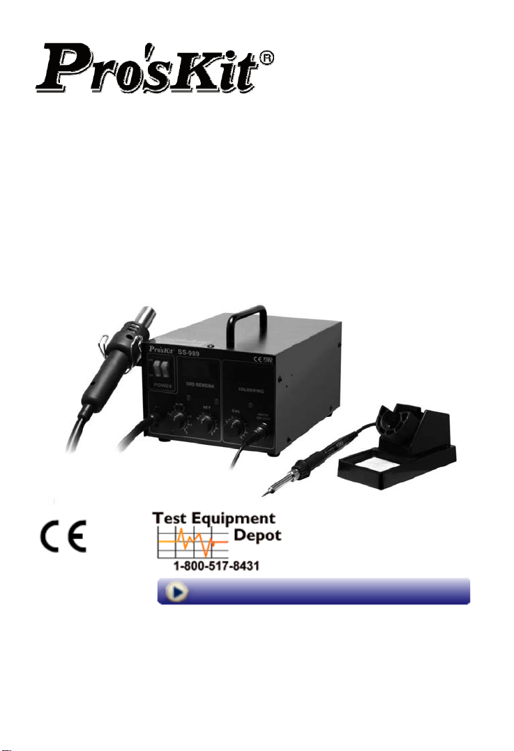
SS-989
2 IN 1 SMD HOT AIR REWORK STATION
User’s Manual
st
1
Edition, 2012
©2012 Copyright by Prokit’s Industries Co., Ltd.
Visit us at www.TestEquipmentDepot.com
99 Washington Street
Melrose, MA 02176
Phone 781-665-1400
Toll Free 1-800-517-8431
Page 2

SAFETY INSTRUCTIONS
WARNING
Warnings and cautions are placed at critical points in this manual to direct
the operator's attention to significant items. They are defined as follows:
WARNING: Failure to comply with a WARNING may result in serious injury
or death.
CAUTION: Failure to comply with a CAUTION may result in injury to the
operator, or damage to the items involved. Two examples are
given below.
NOTE : A NOTE indicates a procedure or point that is important to the process
being describe.
EXAMPLE : AN EXAMPLE is given to demonstrate a particular procedure, point
or process.
_ Be sure to comply with following WARNINGS and CAUTIONS for your
safety.
WARNING
_ Be sure not to operate the unit with any combination of temperature and air
flow settings that makes the thermal protector trip (the heater lamp turns off
during use). This could damage the unit.
CAUTION
When the power is ON, the temperature of the hot air and the nozzle
ranges from 100 to 450°C (212 to 842°F). To avoid injury to personnel or
damage to items in the work area, observe the following:
_ Do not direct the hot air toward personnel or touch the metal parts near the
nozzle.
_ Do not use the product near combustible gases or flammable materials.
_ Advise those in the work area that the unit can reach very high temperatures
and should be considered potentially dangerous.
_ Turn the power OFF when no longer using the Pro’sKit SS-989 or when
leaving it unattended.
_ Before replacing parts or storing the unit, allow the unit to cool and then turn
the power OFF.
To prevent accidents and failures, be sure to take the following
precautions:
_ Do not strike the hand piece against hard surfaces or otherwise subject it to
physical shock.
_ Be sure the unit is grounded. Always connect power to a grounded receptacle.
1
Page 3
_ Do not disassemble the pump.
_ Do not modify the unit.
_ Use only genuine Pro’sKit replacement parts.
_ Do not wet the unit or use the unit with wet hands.
_ Remove power cord by holding the plug – not the wires.
_ Make sure the work area is well ventilated.
_The Pro’sKit SS-989 is not intended for use by children or infirm persons
without supervision.
_ Children should be supervised to ensure that they do not play with the SS-989.
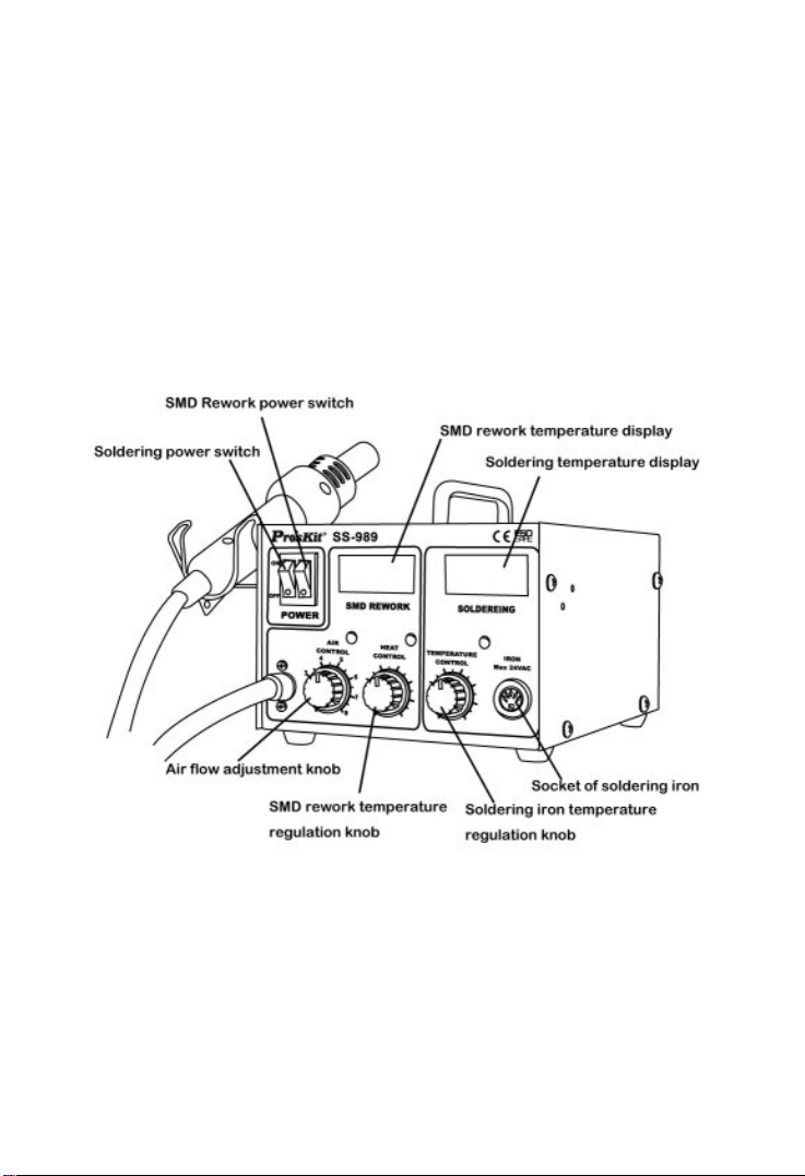
I. Packing list and name of parts
Name of Parts
Packing List
2
1. 1.SS-989 2 in 1 SMD Hot Air Rework Station
2. User’s manual
3. Soldering iron
4. Soldering iron Stand
5. Heat Gun holder
6. Air nozzle x 3
Page 4

II. Features and Specifications
Features:
2 in 1 Rework Station to save the cost
Antistatic soldering iron and hot air desoldering 2 in 1 design to save the cost.
Closed Circuit Sensor Design
Closed-loop temperature control for accurate and air-flow-independent
temperature
High Power, Quick Warm Up Times
High heating power, warm up quickly, adjustable temperature and air flow for
easy surface or hole mount components QFP, SOP type IC devices rework.
Individual Function Start Save Energy
Individual function starts save energy, or share function by 2 users at the
same time, three knobs control hot air volume, hot air temperature, and
soldering iron temperature.
LED Digital Display
Digital LED displays for both rework and soldering station
Quiet in operation
Diaphragm pump with maximum capacity at 24L/min, equipment noise less
than 45dB, wind volume and temperature are adjustable, suitable for many
kinds of use
Auto Cool-Off Process
After power switch is turned off, the auto cool-off process leaves the blower
on until the nozzle is cool in order to prolong the life of heating element and to
ensure safety
ESD Safe Design
Prevent static and leakage electric to damage the PCB.
Interchangeable hot air nozzles and tips
Interchangeable hot air nozzles and tips design for different type of surface
mount components. Also applicable to most of branded nozzles and tips.
3
Page 5
Specification:
Model
Input voltage
SS-989B
SS-989H
AC220V
50Hz
Fuse 3A 250V 6A 250V 5A 250V
SS-989A SS-989A7 SS-989B4 SS-989C
AC110V
60Hz
AC127V
60Hz
AC240V
50Hz
3A 250V
Total power 700W
Overall package
size (mm)
330 (L) * 275 (W) * 195 (H)
Weight 3.7 kg
SMD Rework Specifications
Power
consumption
640
Air pump Diaphragm type
Volume 24L/min (max)
Temperature of hot
air
100℃-450℃
Noise Noise < 45dB
Scale LED display
Soldering Iron Specifications
Power consumption of soldering iron 60W
Temperature range of soldering iron 200℃-480℃
Leakage voltage of soldering iron tip <0.5mV
Assembly
A. Station assembly
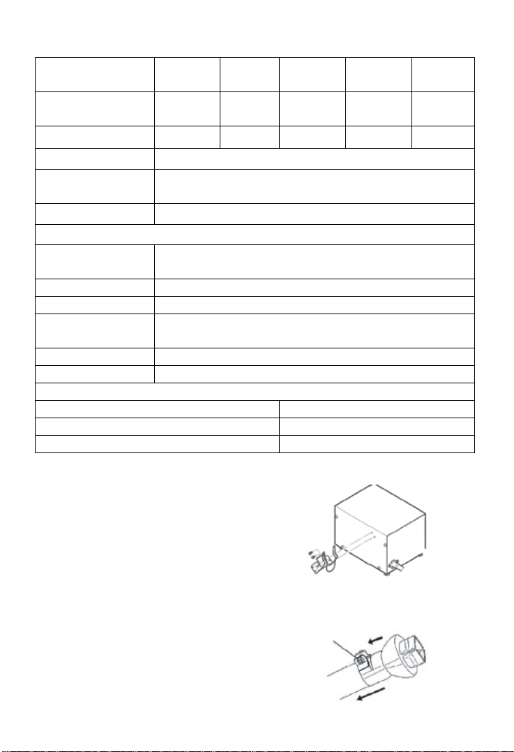
● Attach the Heat Gun holder
Remove the heat gun holder screw
from the side of the station; attach the
heat gun holder to the station (Fig. 1)
B. Attach the nozzle
● Loosen the nozzle mounting screw,
attach the nozzle on heat gun then screw it.
Show as the figure 2
4
AC240V
50Hz
3A 250V
Fig. 1
Fig. 2
Page 6
C. Electrical Connection and Power ON
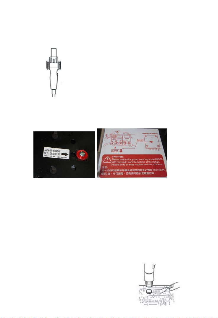
●Place the heat gun on the holder.(Fig3)
●Loosen the pump securing screw which on the bottom of control station.
(See below pictures)
●Insert the power plug into socket
●Turn on the power switch and the lamp will be lit
●Don‘t pull out the power plug instantly after turning off the power switch,
because the fan keeps operating to protect heat element. Until the fan
stops operation completely, the power plug should not be pulled out.
III. Operation instructions (SMD rework)
●Remove SMD components (such as QFP, SOP, PLCC and so on)
1. Adjust air flow and heat gun temperature to desired level
2. Slip the pick-up puller (optional part)
under the component lead. (Fig. 4) If
the width of the component does not
match the size of the pick-up, adjust
the width of the pick-up by
Fig3
Fig. 4
5
Page 7
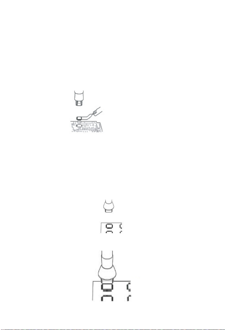
squeezing the wire. In case of PLCC or small components such as chip
resistors, desolder by using tweezers, etc.
3. Hold the heat gun up on the SMD components, but do not touch the
components, and allow the hot air to melt the solder. Be careful not to
touch the leads of the components with nozzle.
4. When the soldering tin is melted, remove the SMD components by
lifting the pick up puller (Fig. 5)
Fig. 5
5. After removing SMD components, remove residual soldering solder tin
with desoldering tool.
●SMD rework operation instructions
1. Apply proper quantity of solder paste and install the SMD components
on PCB.
2. Refer to (Fig. 6) to preheating components
3. Heat the lead frame evenly (Fig. 7)
6
Fig. 6
Fig. 7
Page 8
4. Cleaning
When soldering is completed, clean the residual flux from the board
with an appropriate cleaner.
IV. Soldering iron operation instructions
1. Soldering iron stand assembly
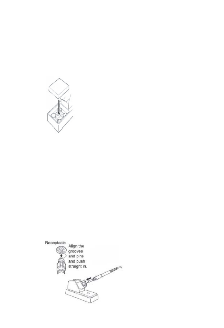
● Install the cleaning sponge into the seat. (Fig. 8)
Fig. 8
***ATTENTION***
Sponge will swell when wet. Dampen the sponge with water and
squeeze dry before using. The tips may be damaged when used
with dry sponge.
2. Insert soldering iron into the stand. (Fig. 9)
3. Take out the protection tube on the top of soldering iron.
4. Connect soldering iron cable to the 5 hole socket on control station. (Fig.
9)
***ATTENTION***
Switch off the power before inserting or pulling out the plug
Fig. 9
7
Page 9

5. Insert power plug into power socket then turn on power switch.
6. Adjust temperature with regulation temperature knob.
***ATTENTION***
High temperature shortens tip life and may cause thermal shock to
components. Always use the lowest possible temperature when
soldering. It will also provide better protection for some components
which sensitive to temperature.
***ATTENTION***
Always put soldering iron into holder after use.
***ATTENTION***
Always clean the soldering iron tip after use and coat it with fresh
solder to prevent oxidation and prolong tip life.
7. Soldering iron tip maintenance and operation
● Always clean the soldering tip before use to remove any residual
solder or flux adhering to it. Use a clean and moist cleaning sponge.
Contaminants on the tip have many detrimental effects including
reduced heat conductivity which contribute to poor soldering
performance.
● If the soldering iron is not in use, do not keep it at high temperature
for long time otherwise the tin flux will become oxidized and reduce
heat conductivity function.
● After use, always clean the soldering iron tip after use and coat it with
fresh solder to prevent oxidation and prolong tip life.
●Checking and cleaning the soldering iron tip
***ATTENTION***
◆ Never cut the oxide on soldering iron tip by cutter.
◆ Set the temperature at 250℃or 482.℉.
◆ After the temperature is stable, clean soldering iron tip with
sponge, and check its condition. If the tip is badly worn or
deformed, replace it.
◆ If the tin-plating part of soldering iron tip covered with black oxide,
8
Page 10
apply fresh solder containing flux and clean the tip again. Repeat
until all the oxide is removed then coat the tip with fresh solder.
◆ If the soldering iron tip gets deformed, replace it with a new one.
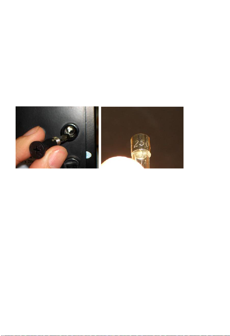
V. Fuse replacement
When fuse is blown, replace it with the spare fuse. (see below picture)
1. Unplug the power cord from the power receptacle
2. Use the Phillip (+) type screwdriver to loosen the fuse holder
3. Replace the fuse with new one
4. Put the fuse holder back in place
9
Page 11
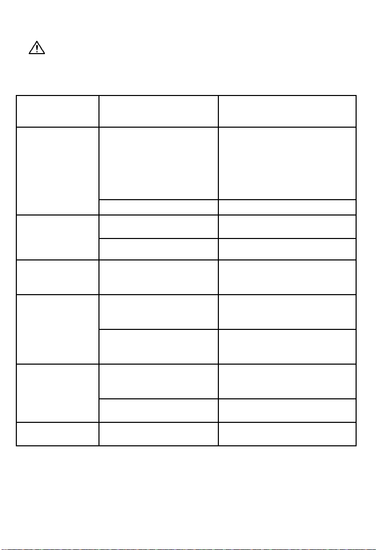
Trouble shooting
Warning:
Before checking the inside of the SS-989 or replacing parts, be sure to
disconnect the power plug. Failure to do so may result in electric shock.
Defect
Situation
Dead, Doesn’t
work
Soldering Iron
doesn’t heat up
Heat Gun air
Temperature
doesn’t heat up
Heat Gun airflow
level abnormal
Display shows
abnormal
Temperature unit
display abnormal
Other problems not mentioned:
Contact the vendor
Possible Problem Solution
Change new fuse
SS-989A(110V) 250V 6A
SS-989B(220V) 250V 3A
Blown fuse
SS-989A7(127V) 250V 5A
SS-989H(220V) 250V 3A
SS-989B4(240V) 250V 3A
SS-989C (240V) 250V 3A
PCB Board broken Contact vendor for repair
Panel display S-E, plug
didn’t connect properly
Heating Element broken Replacing heating element
Heating Element broken Replacing heating element
Internal pipe obstruction
or loosen caused air
leakage
Pump securing screws
haven’t loosened
Transportation caused
inside PCB board didn’t
connect properly
Input voltage lower than
standard request
IC broken Contact vendor for repair
Reconnect the plug of
Soldering Iron
Clearing the internal pipe,
reconnect the pipe tightly.
Loosen the pump securing
screw which on the bottom of
control station.
Open the case, reconnect the
PCB board
Check with local power service
provider
 Loading...