

Page 1
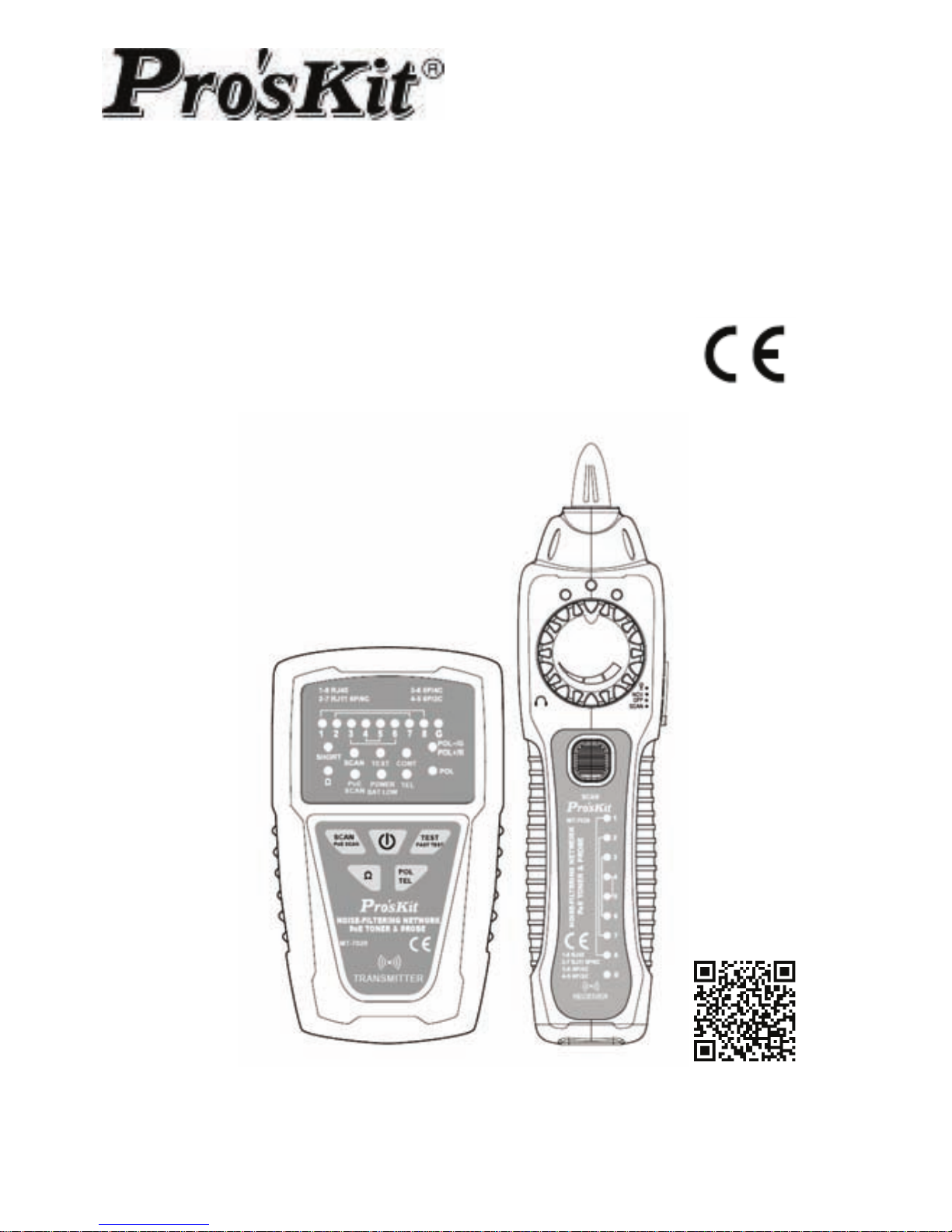
MT-7029
Noise-Filtering Network PoE
Toner & Probe
User’s Manual
2
ed
Edition
©2017 Copyright by Prokit’s Industries Co., Ltd.
Page 2

1
Page 3
2
Thank your for your purchase of Pro’sKit MT-7029 Noise-Filtering
Network PoE Toner & Probe. The Toner and Probe set is used to
quickly trace and identify cables or wires within a group without
noise and also check the operation of telephone lines. With proper
use and care, this instrument will provide many years of reliable
service.
OVERVIEW
MT-7029 with EMI filters to eliminate high frequency noise, for which
allows user to quickly locate and verify the cable status and
troubleshoot wiring for continuity, shorts, opens and crossover on
RJ45, Lan cable Cat 5、5e、6 (UTP/STP), RJ11/12 telephone cable
Cat. 3 (2/4/6 pin) & normal solid/stranded wire by alligator clips
patch cord. Telephone line polarity and status (severed lines, the
off-hook
condition, or incoming call ringing) can be indicated and detected
easily as well.
Ideal for all installation and maintenance fields of telecommunication,
networking, datacom, Audio/Video, cable TV, and all weather
cabling, etc.
SPECIFICATIONS
MT-7029 Transmitter specifications
Tone frequency 130KHz
Max. distance of transmission ≧3km
Max. distance of cable map 300m
Max. working current ≦70mA
Tone mode Single tone
Compatible connectors
for RJ45(8 pin)/RJ11(6 pin) cable map test.
RJ45 SCAN socket : for RJ45 locating
individual wire pairs
RJ11 SCAN socket: for RJ11 locating
individual wire pairs
Cable types
RJ45 Lan cable Cat 5、5e、6(UTP/ STP)、
RJ11/12 telephone cable Cat 3
(6P/2C/4C/6C)
Function selection
5 Press button switch (PO WER、SCAN
/
PoE
SCAN、TEST/F AS T TEST 、Ω、POL/TEL)
Page 4
3
Continuity test
1 LED (≦300Ω), Coaxial cable & normal
solid/Stranded wire by alligator clips patch
cord.
Max. signal voltage 8Vp-p
Cable map indication 8 LEDs, Fast/Slow dual speed
Shielded indication 1 LED
Telephone line polarity, status
indication
1 Dual color LED
Live telecommunication
equipment test and router test
Yes
Voltage protection DC 48V
Auto power off 1 hour
Low battery display 6.5V (Power LED flashes)
Battery type DC 9.0V (NEDA 1604/ 6F22 DC9V ×1pce)
Dimension (L×W×D) 138×80×35 mm
Weight 140g
MT-7029 Receiver specifications
Frequency 130KHz
The Max. working current ≦115mA
Compatible connectors RJ45(8 pin)/RJ11(6 pin)
Function selection
4 Position mode sw itch (LED、NCV、OFF、
SCAN)
Earphone jack 1
Signal status indication 1 dual color LED & Buzzer
Cable map indication 8 LEDs
Shielded indication 1 LED
NCV indication 1 LED (AC90~1000V,≥50mm,≤100mm)
LED illumination 1 LED
Power indication 1 LED
Battery type DC 9.0V (NEDA 1604/ 6F22 DC9V ×1pcs)
Dimension (L×W×D) 203×50×32 mm
Weight 95g
Accessories
RJ45 cable patch cords、RJ11 cable patch
cords、RJ11 to alligator clips patch
cord,earphone, storage bag, user manual
Page 5

4
Safety Information
Never use the Transmitter or Receiver on live circuits of
more than DC48V or it will result damage.
Never use the Transmitter, Receiver or test wire if they are
damaged. Inspect the cases and test leads for damage before
use.
Disconnect unused test leads and connectors from the
Transmitter when testing telephone circuits.
Never open the case except to change the battery or the fuse;
no user-serviceable parts are inside.
Turn off the Transmitter or Receiver and disconnect all test
leads before replacing the battery.
Use only a 9V battery, properly installed in the case, to operate
the Transmitter and Receiver.
If this equipment is used in a manner not specified by the
manufacturer, the protection provided by the equipment may be
impaired.
Page 6
5
INTRODUCTION
MT-7029 Transmitter:
Do not connect with DC 48V live circuit equipment or it will
result damage.
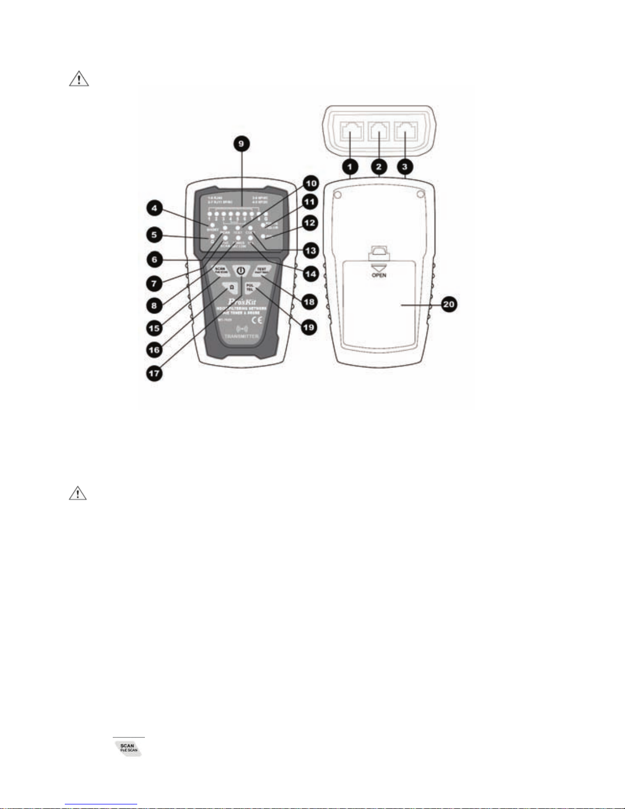
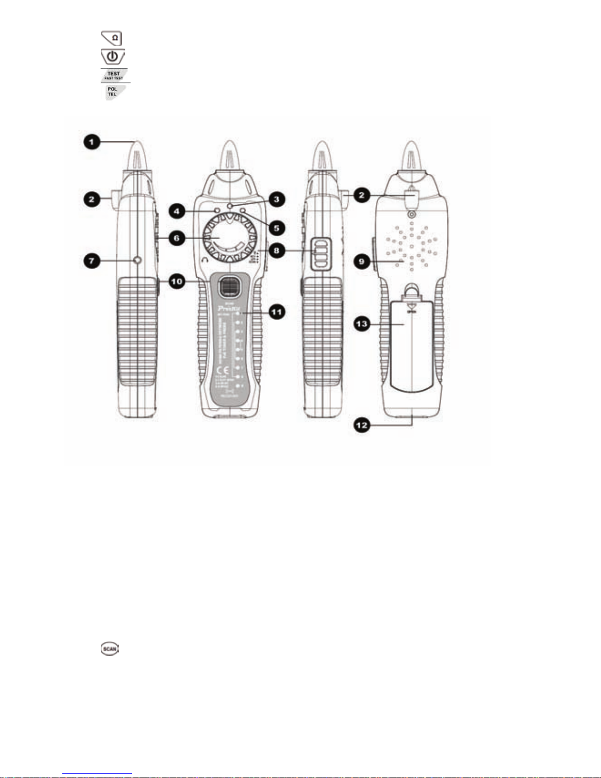
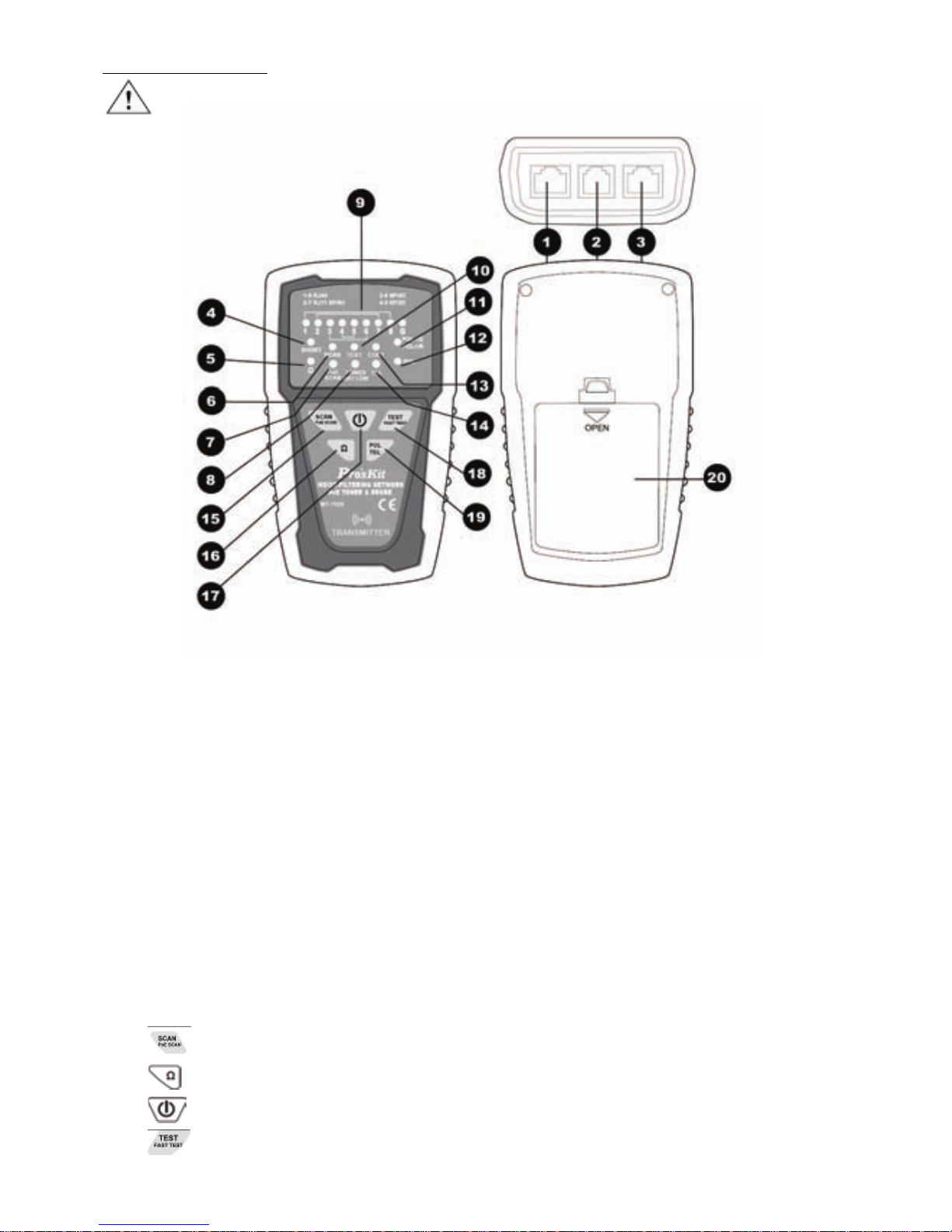
Figure1. MT-7029 Transmitter Diagram
1.「TEST」: RJ45(8 pin)/ RJ11 (6/4/2 pin) cable mapping test socket.
2.「SCAN」: RJ11(6 pin) socket.
3.「SCAN」RJ45 socket.
Caution! Do not plug in any live cable over DC 48V to the
transmitter socket.
4.「SHORT」Continuity test indication
5.「Ω」 Continuity function indicator
6.「SCAN」 Locating and isolating cables function indicator
7.「PoE SCAN」Locating and isolating Cables function indicator
8.「POWER/BAT LOW」 Power ON/OFF & Battery low indicator
9.「1~8、G」 Cable map & Shielded indication
10.「TEST」 Cable map & Shielded function indicator
11.「POL-/G,POL+/R」 Phone line polarity indication
12.「POL」 Phone line polarity function indicator
13.「CONT」Phone line status/polarity indicator
14.「TEL」Phone line status function indicator
15. 「
」Locating and isolating cables function button
Page 7
6
16.「 」Continuity/short function button
17.「
」Power ON/OFF button
18.「
」Cable map & Shielded function button
19.「
」Phone line polarity function button
20. Battery cover
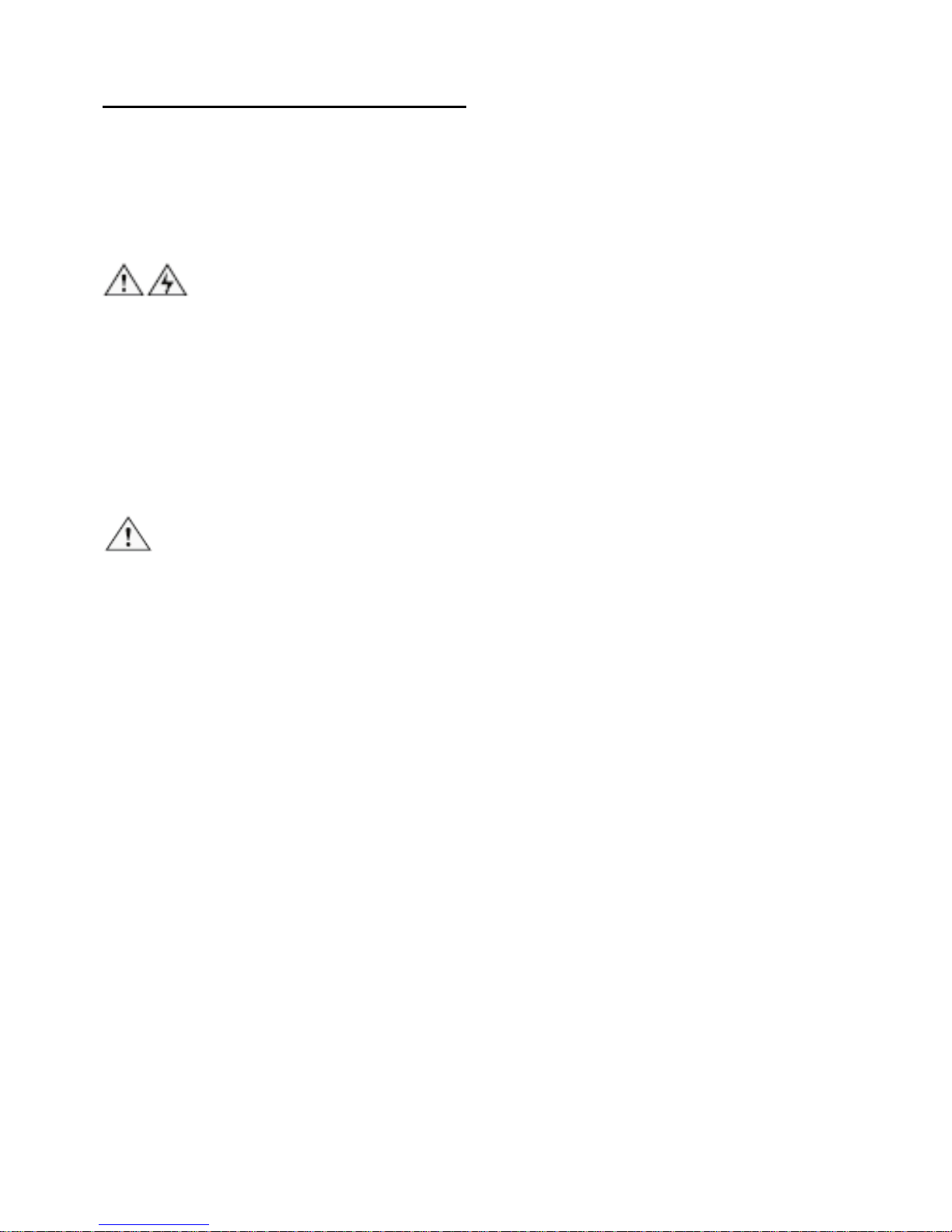
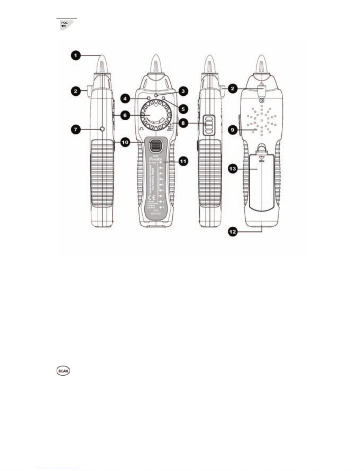
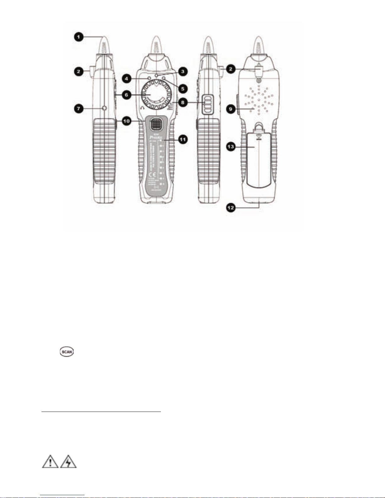
Figure 2. MT-7029 Receiver Diagram
1. Probe:Used for cable tracing and NCV detection.
2. LED light
3. Power ON/OFF indicator
4. NCV indicator
5. Signal status indicator
6. Volume control
7. Earphone jack Φ3.5mm
8. Function switch (LED/NCV/OFF/SCAN mode)
9. Speaker
10.「
」 Locating and isolating cables function button
11.「1~8、G」 Cable map & Shielded indication
12. RJ45(8 pin)/ RJ11 (6/4/2 pin) cable mapping test socket.
13. Battery cover
Page 8
7
OPERATION
Locating and Isolating Cables:
Using MT-7029 to locate and insolate cables using the 130KHz
analog, also trace twisted wires (UTP, STP, Cat 5, Cat 5e, Cat 6)
and telephone line(Cat 3). Use with a patch cord for RJ45 / RJ11
coaxial cable, general cable and various wiring boards can be tested
by using with alligator clip cable.
Warning
• It is not intended to be used on live wires with a DC power
source over DC 48V (e.g., live telephone lines), nor will it work
on wire pairs that are carrying AC signals.
• Use RJ45 SCAN compatible connector for RJ45 cable tracing.
Use RJ11(6 pin) connector for RJ11(6P/6C/4C/2C) cable tracing.
Use RJ11 (6 pin) connector and work with alligator clips for
coaxial cable, general cable and various wiring boards.
Caution
• The position on the MT-7029 lets you use the Receiver to trace
using an analog 130KHz tone. When using the Receiver to
isolate the tone source in the cable bundle or at the patch panel,
the signal might be interfered with or decreased and the signal
will not pass through metal tubes.
• It is not necessary to touch the Receiver’s tip to the cable or
patch panel when searching for the Transmitter’s signal.
• Make sure the black alligator clip of the Transmitter is connected
to the ground before use.
• When using the MT-7029 with earphone to locate and isolate
cables, please keep probe away from the earphone to avoid
interference of resonance effects
• When doing cable locating, if the signal becomes intermittent,
trailed off or interrupted, the receiver may be disturbed by the
harmonics of other devices. Please move your position for better
signal.
• Different PoE injector may cause Receiver signal to be
intermittent, trailed off or interrupted; please move your position
for better signal.
• When doing PoE scan, bigger current consumption, which will
Page 9

8
decrease the battery life time, may occur according to different
PoE equipments, and it is normal.
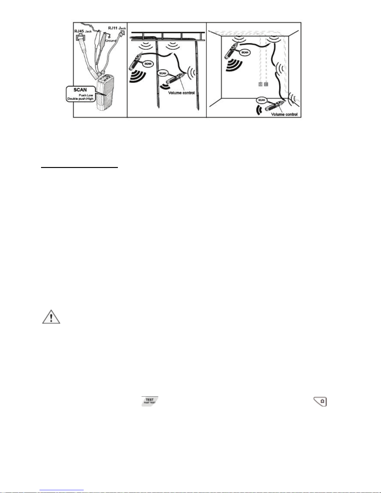
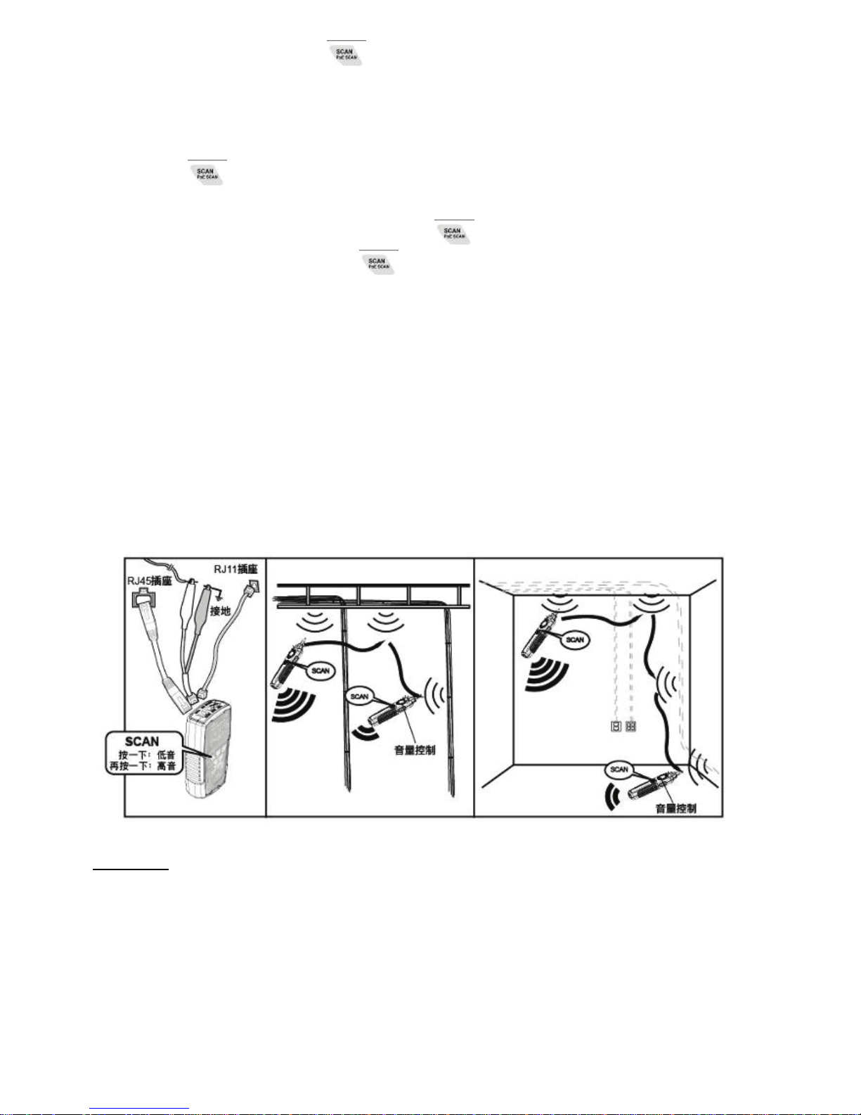
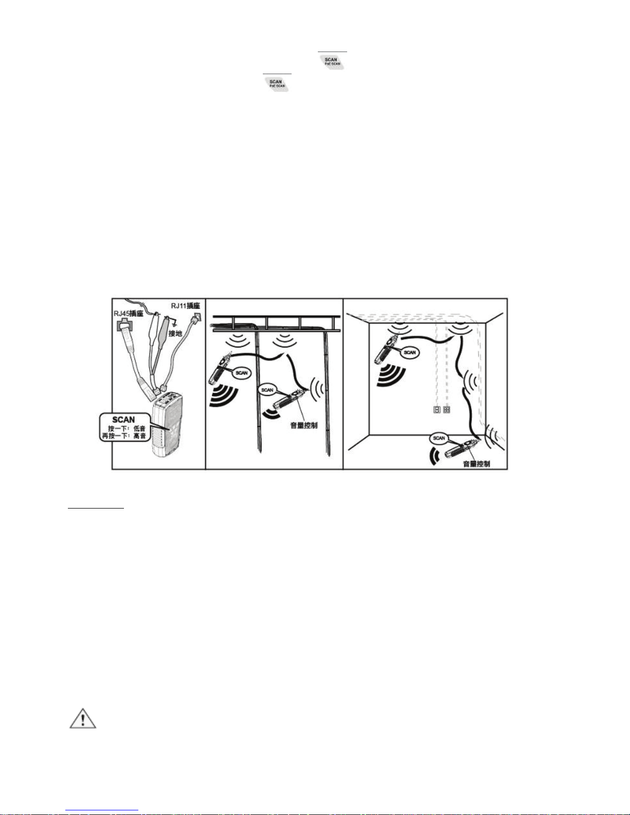
To locate cables, do the following steps (Figure 3):
1. Connect the black alligator clip of the Transmitter to the ground,
and then connect the red clip to a jack or punch-down block as
shown in Figure 3.
2. As the Figure 3 shown, when push
, the red indicator of
“POWER/ BAT LOW” will light up and turn on the power.
SCAN : Press
button for cable tracing. When the red
“SCAN” indicator lights up, the cable tracing is working.
PoE Switches SCAN : Press the
button twice for PoE
switches cable tracing. When the red “PoE SCAN” indicator
lights up, the cable tracing is working.
PoE SCAN function applicable with PoE switches and network
switches.(In the cable tracing process, if the sound is weak,
perhaps cable did not connect to the PoE switches/network
switches or cable is broken, please switch to "SCAN" mode)
Press
button again, stop tracing.
3. As the figure 3 shown, put the receiver function switch at "scan",
the red indicator in the middle will light up, and long press“
”
on receiver to operate cable tracing function. The tracing sound
will be output from speaker. When put on the earphone, there
will be no sound from speaker, but from the earphone.
4. Use the Receiver to find the cable location from the cable rack,
patch panel, or behind the wall. The closer the cable locates, the
louder signal sound will be. The signal status indicator will
change from red to blue, and the brightness depends on signal
strength. If the blue LED indicator light is not bright, there is no
signal.
5. Adjust the volume control on the receiver to locate the wire pairs
from 0 cm to 15cm.
Page 10
9
Figure 3 Locating cables
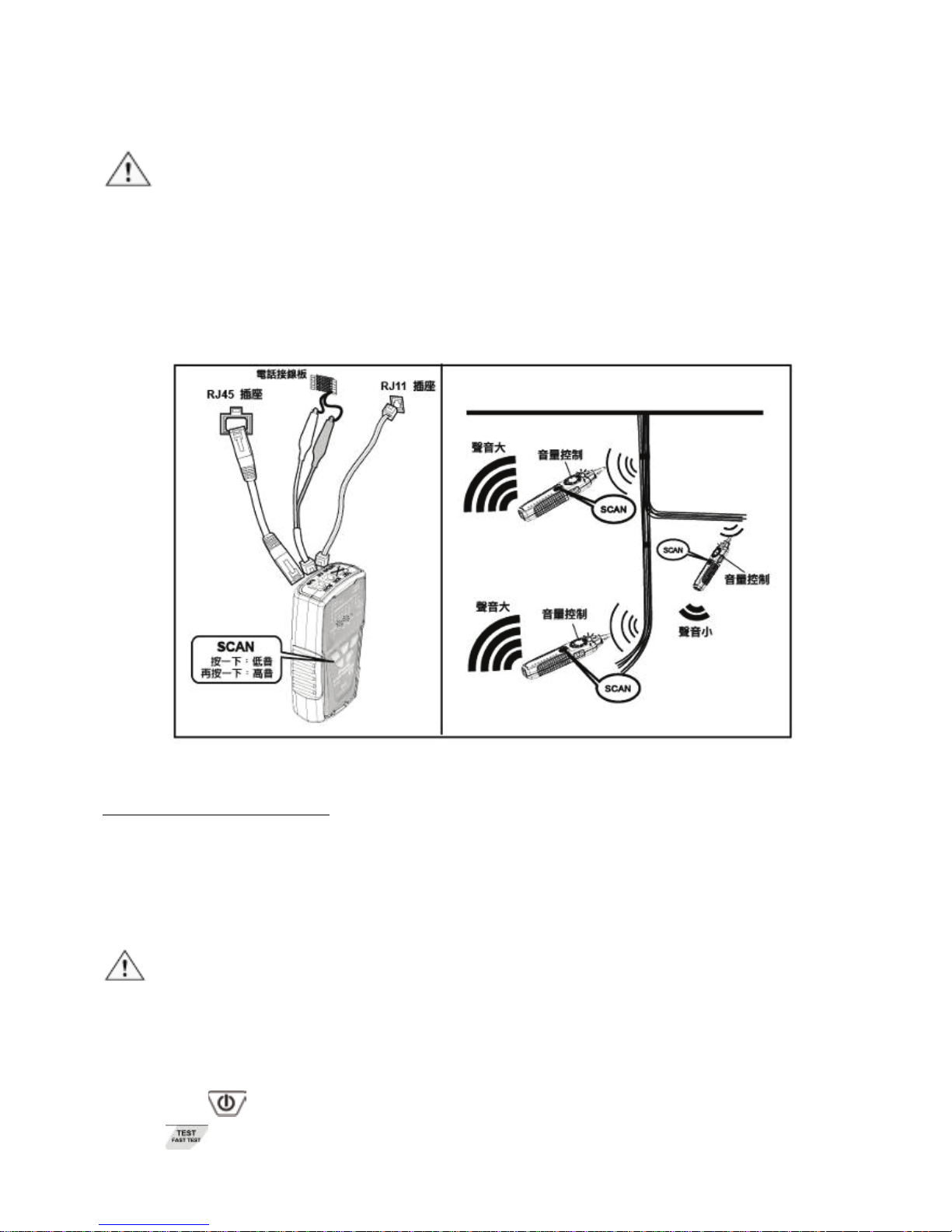
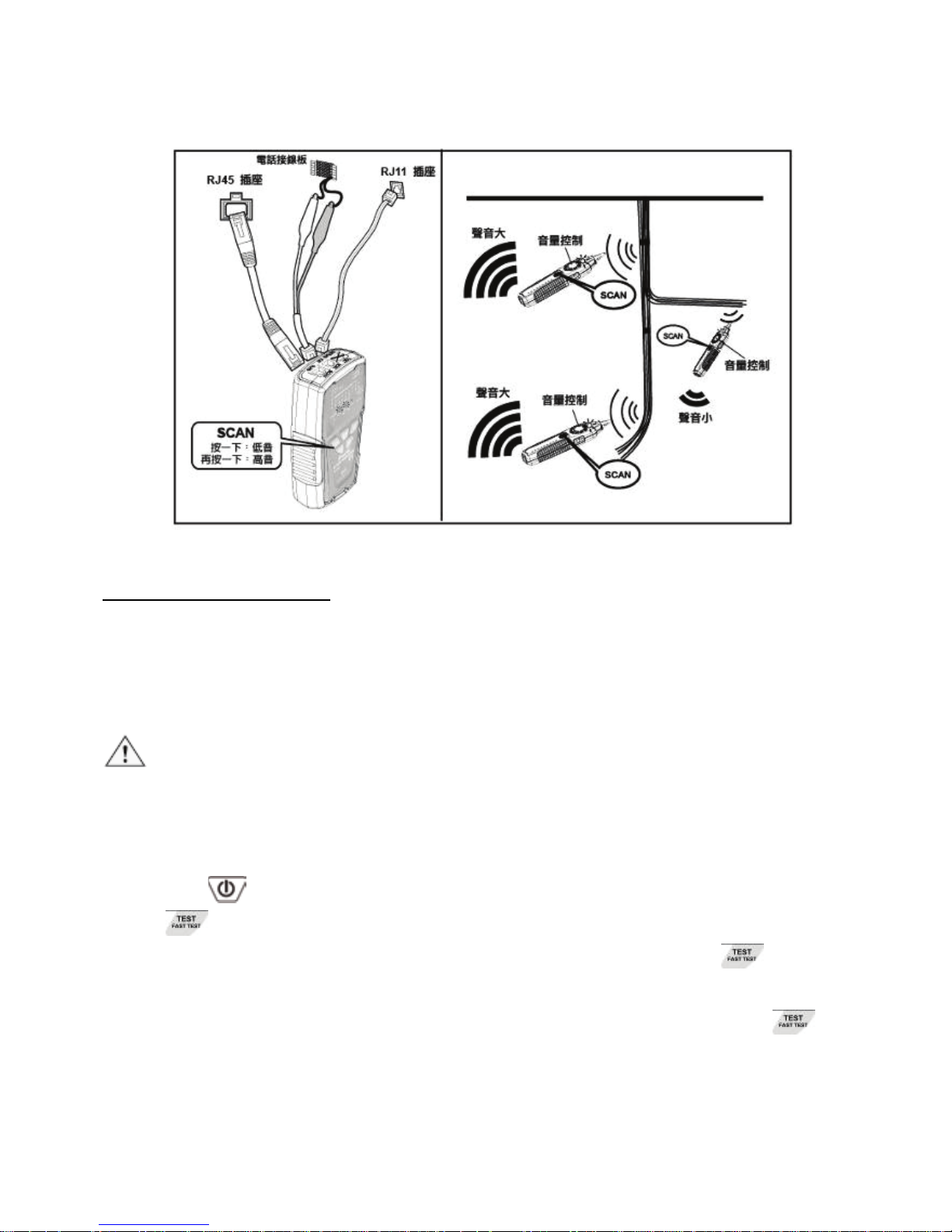
Isolating Cables:
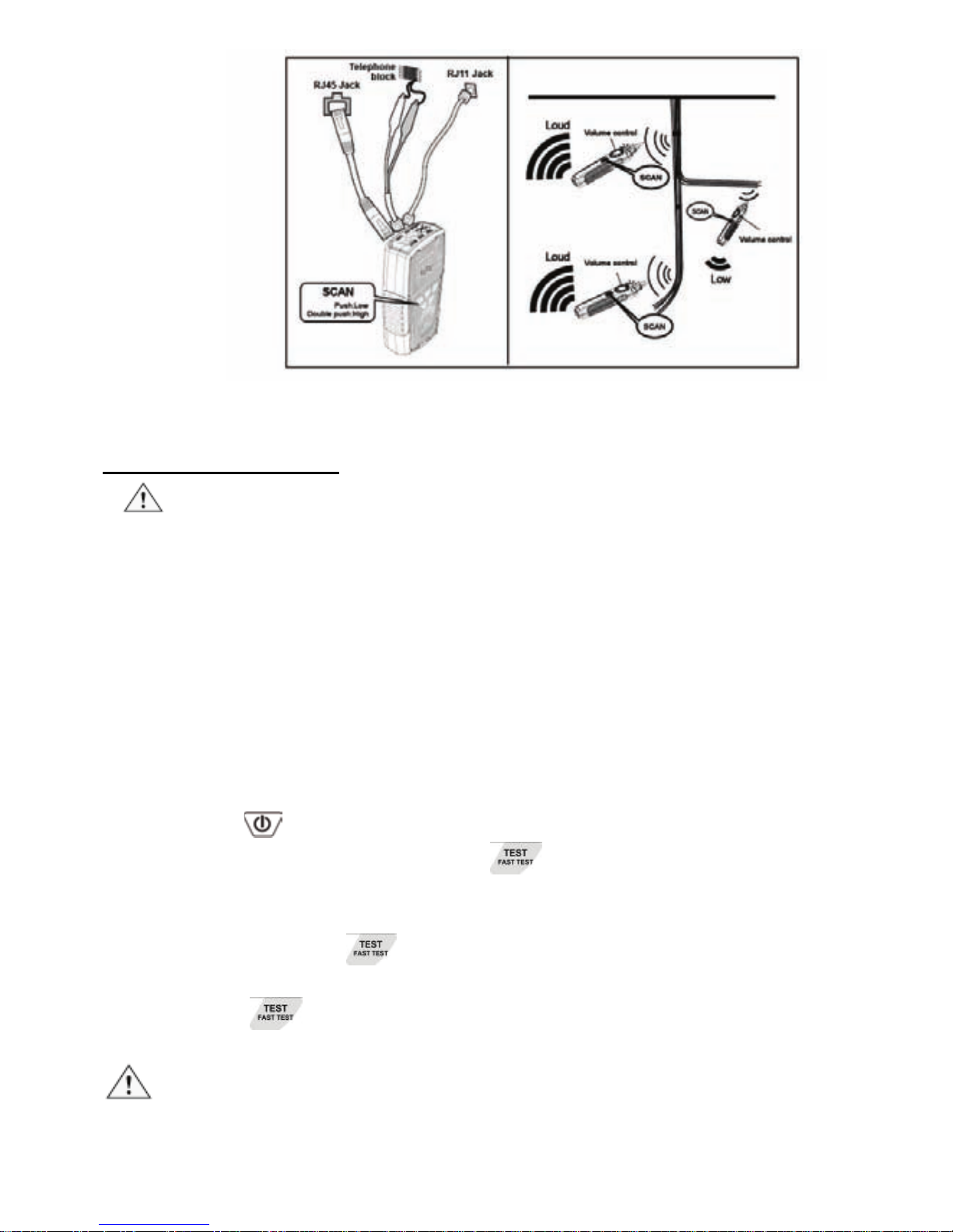
To isolate the tone source in the cable bundle or at the patch panel,
do the steps as described in the previous section of “Locating
Cables”.
1. Strip the cable’s shield to a length of between 30 to 45
centimeters and divide the wires into two parts. Do the wire
separation to isolate the cables to verify the signal of each part.
If the beeper gets louder and LED lights up, you have located
the position you are looking for.
2. Adjust the volume control from high to low to locate the wire that
more difficult to be identified. Narrowing the length from 15 to 0
centimeters will help to identify the wire pairs more accurately.
3. Repeat the steps of 1 and 2 to isolate the bundled cables.
Caution
• If you cannot locate the MT-7029 signal on 2-conductor cables,
the cable may be shorted or opened. Use the Continuity Test to
check for shorts or opens on coax and non-terminated cables.
If cables are connected to the switches, it may not easy to find
the signal from MT-7029; please try to turn off the switches or
pull out the cable 1 pce a time to check the signal. If signal is still
hard to found, use "
" Cable map & Shielded function or " "
Continuity function test to check cable connection.
Page 11
10
Figure 4 Isolating Cable
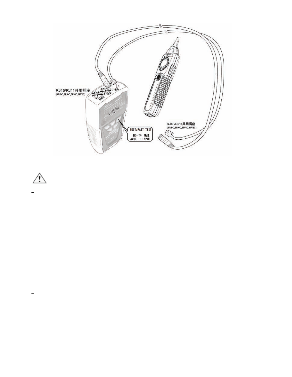
Cable Map Testing:
Caution
• When use the product for RJ45 or RJ11 cable mapping, please
only plug in the cable to the RJ45/RJ11 “TEST socket” on the
transmitter. Do not use RJ45 SCAN or RJ11 SCAN socket.
• You can use the MT-7029 Transmitter or Receiver to validate
the cable map on RJ45/RJ11 by RJ45/RJ11compatible
connector on transmitter. The cable map function finds the most
common wiring faults on twisted pair cabling: shorts, opens, and
crossed pairs.
1. Connect the MT-7029 Transmitter or Receiver to RJ45/ RJ11
jacks.
2. Press“
”, the indicator of “POWER/ BAT LOW” will light up
and turn on the power. Press“
” on MT-7029 transmitter
for cable mapping and shielded function indication. When the
green LED indicator flickers slowly, the low speed scan is
working. Press “
” button again, the green LED indicator
flickers faster, and the fast speed scan will be operated.
Press “
” button again, the product will be standby for
next operation.
Caution
• Each LED that corresponding to an active pin flashes
briefly and should light for about 1 second. For fast scan
Page 12
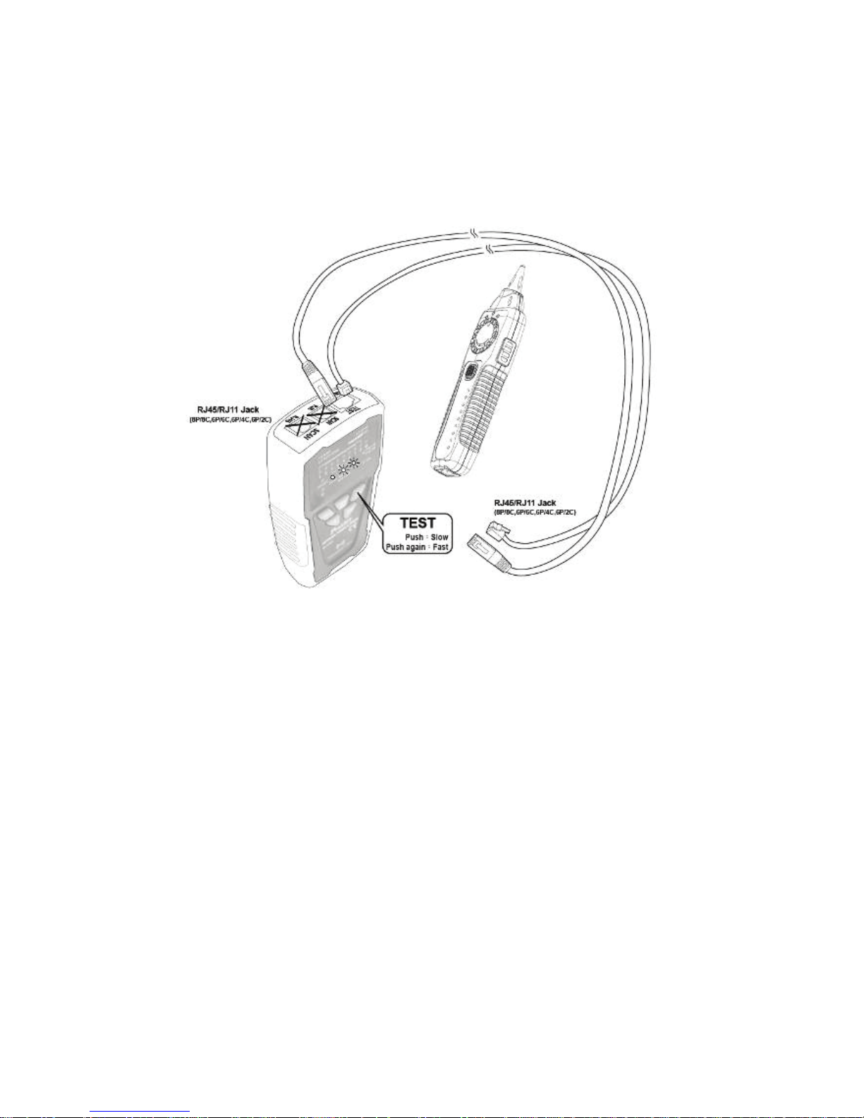
11
cable mapping, the light will flicker about 0.5 second, from
1 to 8, G. If the cable is open, the LED indicator will not
light up.
• Before cable map testing, repeat the procedures of
“Locating Cables” on page 7 to identify the correct
connector or wires on the other end of the cable if
necessary.
Figure 5 Validating Cable Maps
3. Different connectors generate different LED and sound
indications as shown in Figure 4.
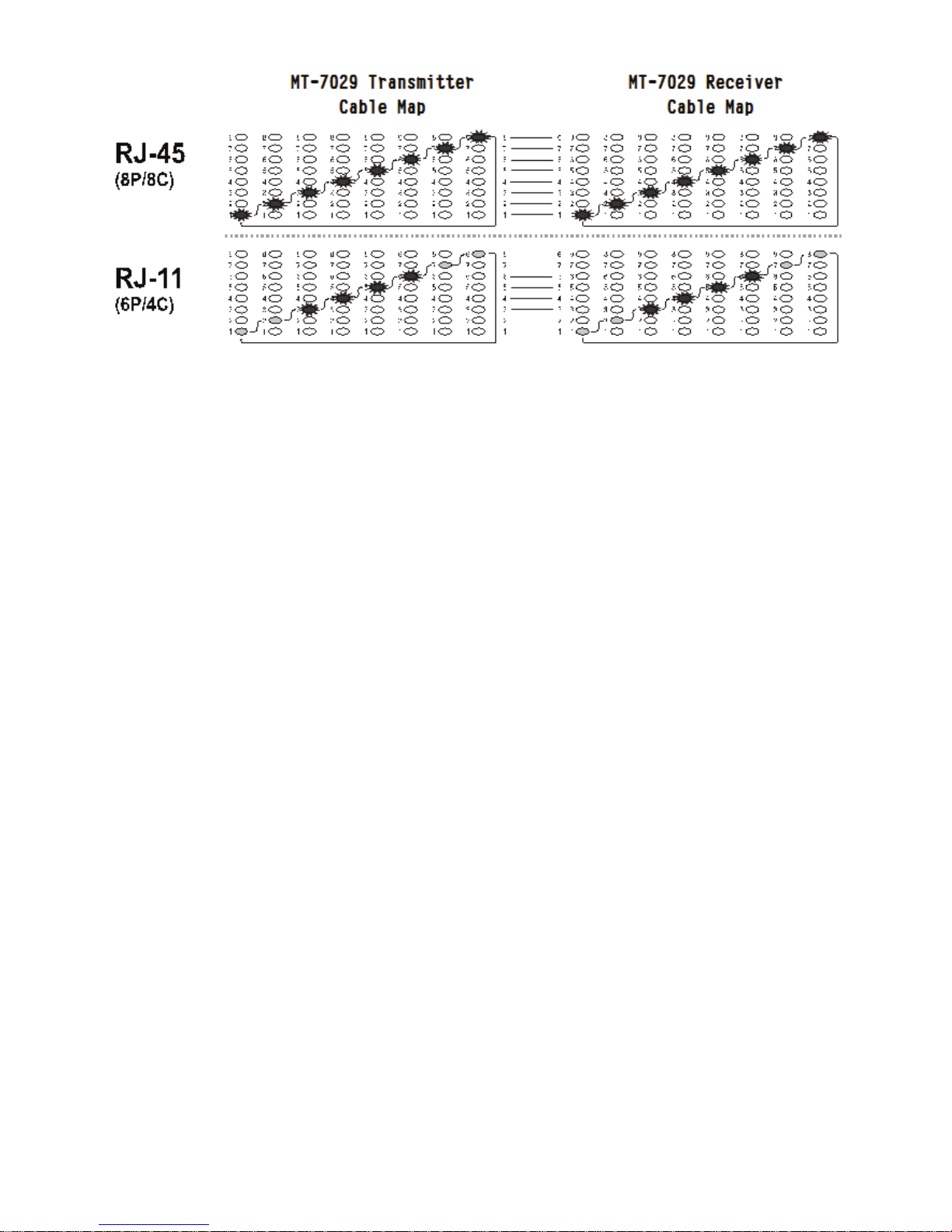
• RJ45(8P/8C) LED indication:MT-7029 Transmitter (from
1-8 seconds in sequence) is synchronized with the
MT-7029 Receiver cable map.
• RJ11(6P/6C, 6P/4C, 6P/2C) LED indication:MT-7029
Transmitter cable map, 6P/6C each second from 2 to 7 in
sequence, 6P/4C each second from 3 to 6 in sequence,
6P/2C each second from 4 to 5 in sequence is
synchronized with the MT-7029 Receiver cable map. If it
encounters an empty line, the indication will cease.
Page 13
12
Figure 6 Different Connector’s Cable Map
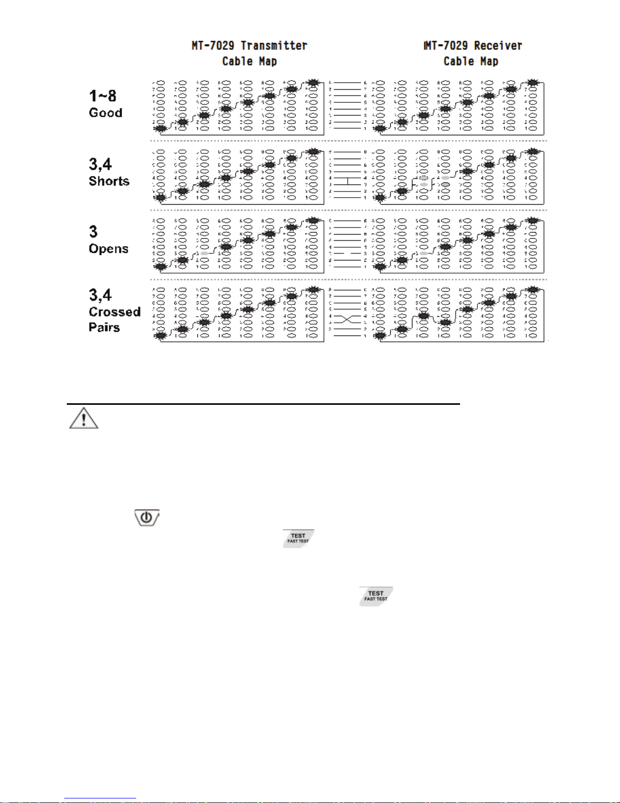
4. You can use the MT-7029 to validate the cable map on RJ11
and RJ45 connectors. The cable map function finds the most
common wiring status on twisted pair cabling: good, shorts,
opens, and crossed pairs as shown in Figure 5.
• Good wiring: Each LED that corresponding to an active
pin flashes briefly and in a stairway order.
• Shorts: If two LEDs turn on for 1 second at the same time,
those two pins are shorted together. If more than 2 wires
are shorted together, the LEDs for the shorted pins
indicate opens.
• Opens: If an LED flashes briefly, then no LEDs turn on,
that pin is open.
• Crossed pairs: If one LED flashes briefly, then another
LED lights for one second, the wire for the first LED is
crossed pairs to the pin for the second LED.
5. Each LED that corresponds to an active pin flashes briefly, it
should light for about 1 second. The brief flash shows which
LED is next in the sequence.
Page 14
13
Figure 7 good wiring, shorts, opens, crossed pairs
Live Telecommunication Equipment and Router Test:
Caution!
The feature can only be used for testing cable continuity and opens,
cannot be used for cross over and short.
1. Connect MT-7029 transmitter and working router by RJ45 cable
map test socket.
2. Press
button to turn on the power, “POWER/ BAT LOW”
indicator will light up. Press
button on transmitter to feature
cable map function. When the TEST indication green LED
flickers slowly, the slow cable mapping is working and the red
cable map LED starts scanning. Press
button again, the
TEST indication green LED twinkled fast, the fast cable mapping
is working and the cable map LED starts scanning. Press the
button again, the TEST green LED light will be off and the
product will be standby for next operation.
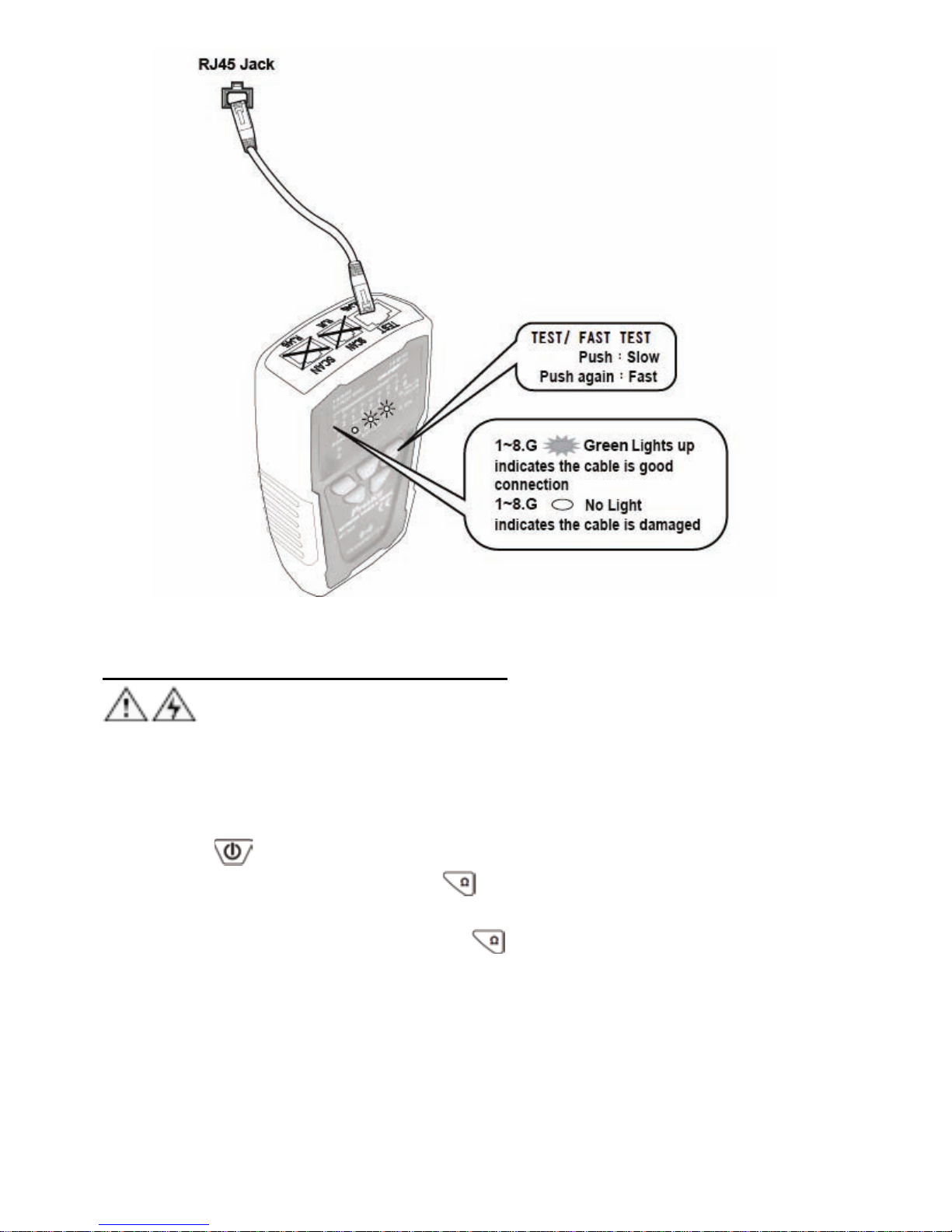
3. When the “1~8, G” LED indicator on MT-7029 transmitter lighted
one by one, the cable (1~8, G) is good. If any of LED indicator is
not lighted, the cable is damaged.
Page 15
14
Figure 8 Cable testing on working line
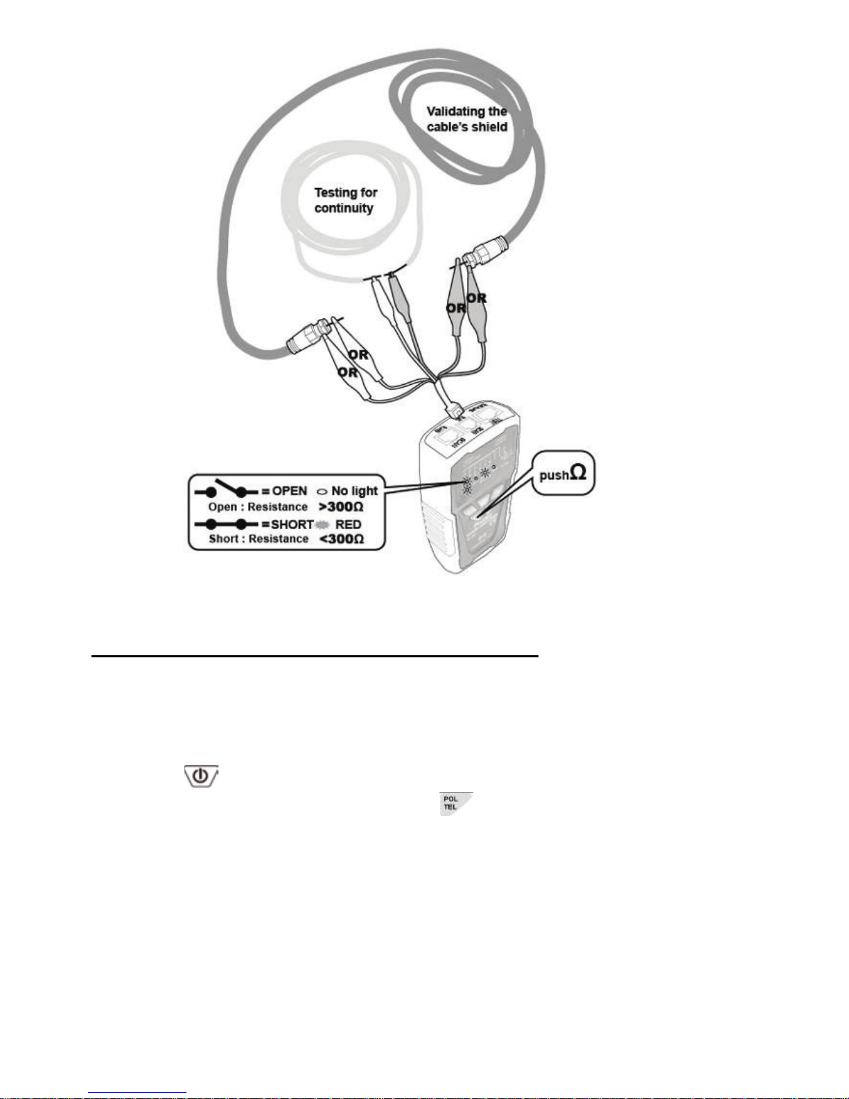
Coaxial Cable & Continuity Testing:
DANGER
Before testing, please be sure the power of receiver is OFF.
To validate cable shield during cable map tests, do the following as:
1. Connect the Transmitter to the circuit as shown in Figure 9.
Connect the test leads to the coaxial cable to be tested.
2. Press“
” button to turn on the power, “POWER/ BAT LOW”
indicator will light up. Press“
” button on transmitter for short/
open function, the green LED indicator lights up and the short/
open testing is working. Press“
” again, the green LED lights
off and the product is standby for next operation.
3. When “SHORT” red LED indicator lights up, the cable is
connected. (the resistance of cable is less than 300Ω). If the
indicator is off, the cable is short or resistance of the cable is
over 300Ω .
Page 16
15
Figure 9 Coaxial Cable & Continuity Test
Validating Telephone Service and Polarity:
Please follow the following steps to check the polarity of telephone
lines:
1. Connect the red and black alligator clip of the Transmitter to the
telephone line jack or socket or punch-down block.
2. Press
button to turn on the power, “POWER/ BAT LOW”
indicator will light up. Then press
to operate the polarity
indication feature and the LED indicator will light up. According
to the function of the phone positive/negative polarity test start.
3. 「POL-/G,POL+/R」LED indicator is dual color (Red/ Green).
The LED indicator of the Transmitter indicates the status as
below:
• Red light:Red alligator clip at positive (+) polarity;Black
alligator clip at negative (-) polarity.
• Green light:Red alligator clip at negative (-) polarity;
Black alligator clip at positive (+) polarity.
Page 17

16
• No Light:Non service or line fault.
Phone Status Indication Test
(only used for the analog phone lines,
cannot be used in the digital telephone):
Please complete the following steps to check the status of a phone
line:
1. Connect the red and black alligator clip of the Transmitter to the
telephone line jack or punch-down block.
2. Press
button to turn on the power, “POWER/ BAT LOW”
indicator will light up. Then press “
“ button twice, the ”TEL”
phone line status function indicator will light up, phone status
indication test start.
3. In the phone status indication test, the polarities will
synchronism shown. The “CONT” indicator is dual color (Red/
Green). Indicates the status as below:
• Red light:Red alligator clip at positive (+) polarity;Black
alligator clip at negative (-) polarity.
• Green light:Red alligator clip at negative (-) polarity;
Black alligator clip at positive (+) polarity.
• No Light:Non service or line fault.
4. “CONT” phone status indicator shows test results, it is a
red/green dual color LED lights:
• Red or green color : Standby status.
• Not bright or dim : Served line status.
• Flashing : Incoming call ringing.
NCV (Non-Contact Voltage) Testing:
Caution
• The feature can be used before locating, isolating, cable
mapping to identify if the tested cable is with AC voltage. It can
not only help to ensure the safety of user and avoid possible
electric shock or personal injury, but also protect the product
from being damaged by AC power.
1. Turn the switch to “NCV”, the function is started when the power
indication is on.
2. When doing the NCV testing, place the probe of MT-7029
receiver to the tested cable, the NCV indicator twinkled fast and
Page 18
17
the buzzer sounded means the tested objective is with AC
90~1000V. If the indicator did not come on and no buzzer
sounded, it means the tested objective with AC power less than
90V or there is no AC power on it.
Maintenance & Trouble shooting:
Warning
Turn off the Transmitter or Receiver and disconnect all test leads
before replacing the battery.
Caution
To avoid damaging the case, do not use solvents or abrasive
cleansers. Clean the case with a soft cloth dampened with water or
a mild soap solution.
Trouble shooting
Possible Problems Trouble shooting
Shortage of battery power: Check the
battery on both transmitter and receiver. If
the battery voltage is less than 6.5V, please
replace with a new battery.
Make sure the switch position on receiver is
“SCAN” or ”LED”. The SCAN function will
not work if the switch is at another position.
The signal from
transmitter can not be
detected by receiver
Device damaged: please return the product
to the place you purchased for
maintenance.
No signal received
from transmitter on
Live
telecommunication
device testing
There might be conflict between the signal
from telephone office and the signal from
transmitter. Please turn off the telephone
exchange device.
LED indicator broken: please return the
product to the place you purchased for
maintenance.
Incorrect cable
mapping result
Improper connection of networking or
telephone cables: please reconnect the
cables toRJ45/ RJ11 compatible
connectors.
Page 19

18
NCV NOT WORK
Switch at SCAN position, and push “SCAN ”
button; If the indicator did not light up,
please replace with a new battery
Others
Device damaged: please return the product
to the place you purchased for
maintenance.
Page 20
19
MT-7029 抗干擾型音頻網路 PoE 查線器
使用說明書
感謝您購買和使用 Pro’sKit MT-7029 抗干擾型音頻網路 PoE 查線器,使用本產
品前請仔細閱讀說明書,閱讀後請妥善保存,以備日後查閱。
特點概述:
MT-7029是一款採用最新數位電路技術,能使用戶在查找線纜時避免電磁干擾,
排除噪音,更輕鬆的查找目標線路;診斷RJ45網路線(UTP、STP、Cat 5、Cat 5 e、
Cat 6)、RJ11/12電話線(Cat. 3 (2/4/6 pin)的通路、短路、斷路、交叉等狀況,並提
供STP & PoE交換機線纜的查找與定位;確認電話線的狀態&接線極性;測試一
般電線連接的狀況。配有鱷魚夾,可應用於測試同軸電纜線、一般電線和電信/
網路接線板。
適用於電信、網路通訊、監控、有線電視等室內、外佈線施工或維護等工程使
用。
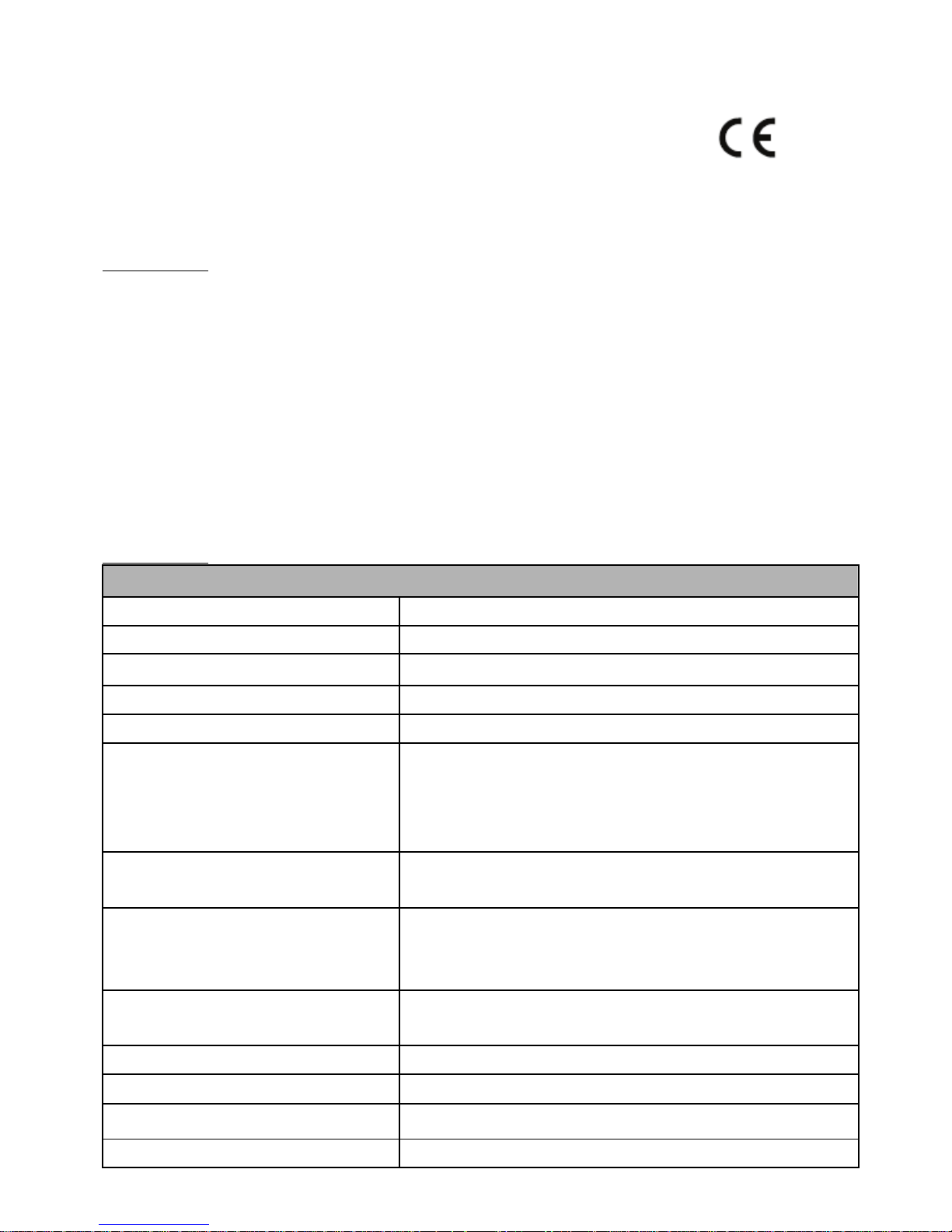
產品規格:
MT-7029 音頻發射器 規格
音頻發射頻率 130KHz
音頻最大測試距離 ≧3 公里
線序/故障最大測試距離 300 米
最大工作電流 ≦70mA
音色 單音調
可測試連接阜
TEST 插座: 提供 RJ45(8 pin)/RJ11(6 pin)線對測試
RJ45 SCAN 插座: 提供 RJ45(8pin)音頻尋線使用
RJ11 SCAN 插座: 提供 RJ11(6P/6C/4C/2C)音頻尋線
使用。
適用電纜線
RJ45 網路線 Cat 5、5e、6(UTP/STP)、RJ11/12 電話
線 Cat 3 (6P/2C/4C/6C)
功能選擇
5 個按式開關(電源、尋線 SCAN/PoE SCAN、線對
TEST/FAST TEST、短路/導通 Ω、電話極性/電話
線狀態 POL/TEL)
短路/導通測試
1 個 LED 顯示 (線路≦300Ω),同軸電纜線和一般
單芯/多芯絞線用鱷魚夾線測試
輸出信號電壓 8Vp-p
線序/故障指示 8 個 LED,快/慢雙速測試
網路線帶遮蔽指示燈 1 個 LED
Page 21
20
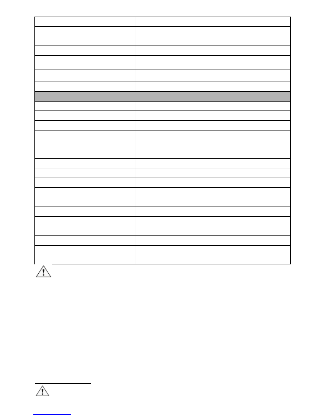
電話線 正/負極性、狀態指示 1 個雙色 LED
電信設備和路由器活電測試 有
電壓保護 DC 48V
自動關機 約 1 小時
電池低壓指示 6.5V (電源指示燈閃爍)
電池 DC 9.0V (NEDA 1604/ 6F22 DC9V ×1pcs)
外觀尺寸 (長×寬×高) 138×80×35 mm
重量 140 公克
MT-7029 接收器 規格
音頻接收頻率 130KHz
最大工作電流 ≦115mA
可測試連接阜 RJ45(8 pin)/RJ11(6 pin) 共用插座
功能選擇
4 段滑動開關(LED 照明、非接觸驗電 NCV、關機
OFF、尋線 SCAN)
耳機座 1 個
信號強弱指示 1 個雙色 LED & 蜂鳴器
線序/故障指示 8 個 LED
網路線帶遮蔽指示 1 個 LED
非接觸驗電(NCV)指示 1 個 LED (交流 90~1000V)
工作照明 1 個 LED
電源指示 1 個 LED
電池 DC 9.0V (NEDA 1604/ 6F22 DC9V ×1pcs)
外觀尺寸 (長×寬×高) 203×50×32 mm
重量 95 公克
配件
RJ45(8pin)網路線、RJ11(6pin)電話線、RJ11(6pin)
對鱷魚夾線、耳機、攜存袋、使用手冊
使用安全
• 請勿連接超過DC 48V的活電線路,以免造成儀器損壞。
• 請勿使用破損的測試器或測試線,使用前請檢查機殼和測試線是否有破損。
• 測試電話電路時,請先將不使用的測試線和連接器從測試器上移除。
• 除非要更換電池,否則不得打開機殼;其中沒有任何用戶可維修的零件。
• 更換電池前請先關機!並將測試線移除。
• 請使用9V電池並正確安裝在機殼內以提供電源。
• 如果不遵照指定方式使用本設備,則可能影響本產品提供的保護。
Page 22
21
MT-7029 部件名稱
任何超過DC 48V的活電的線路,不可接入本儀器任何測試插座,以免造成
儀器損壞。
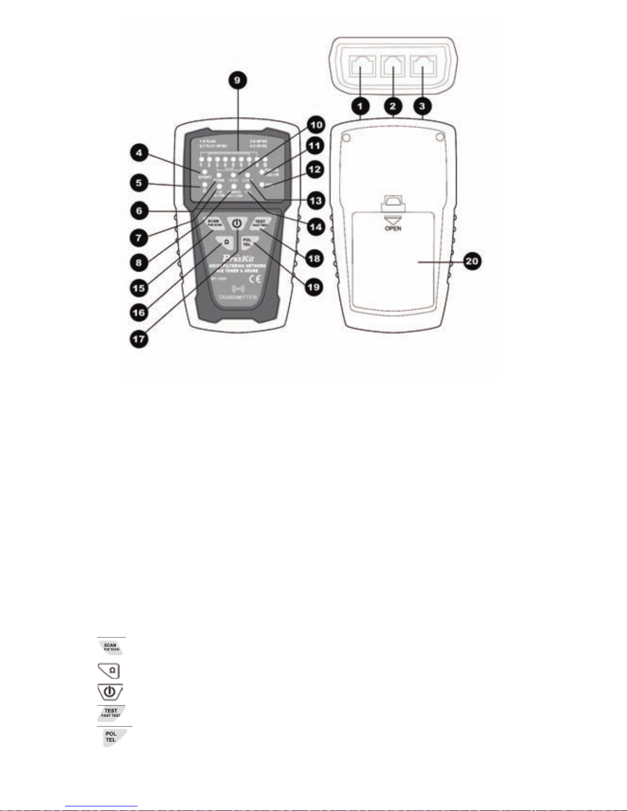
MT-7029 音頻發射器 外觀圖
1.「TEST」:RJ45(8 pin)/RJ11(6/4/2 pin)對線測試插座
2.「SCAN」:RJ11 (6 pin)插座
3.「SCAN」:RJ45插座
4.「SHORT」:短路測試結果指示燈
5.「Ω」:短路/導通功能指示燈
6.「SCAN」:尋線功能指示燈
7.「PoE SCAN」:尋線功能指示燈
8.「POWER/BAT LOW」:電源指示燈
9.「1~8、G」:測試結果指示燈
10.「TEST」:線序/故障功能指示燈
11.「POL-/G,POL+/R」:電話極性測試結果指示燈:
12.「POL」:電話極性功能指示燈:
13.「CONT」:電話線路狀態及極性測試結果指示燈
14.「TEL」:電話線路狀態指示燈
15.「
」:SCAN/PoE SCAN網路&PoE尋線功能鍵:
16.「
」:短路/導通功能鍵
17.「
」:電源開/關鍵
18.「
」:TEST/FAST TEST快/慢線序/故障功能鍵:
Page 23
22
19.「 」:POL/TEL電話極性&電話線狀態功能鍵:
20.電池蓋。
MT-7029 接收器 外觀圖
1.音頻信號探頭
2.LED照明燈
3.電源指示燈
4.非接觸驗電(NCV)指示燈
5.信號強弱指示燈
6.音量旋鈕
7.ø3.5mm耳機座
8.4 段功能開關
9.喇叭
10.「
」尋線功能鍵
11.「1~8、G」測試結果指示燈
12.RJ45(8 pin)/RJ11(6/4/2 pin)測試插座
13.電池蓋。
Page 24

23
使用音訊信號查找、分離電線:
使用MT-7029查找線路時,能定位、分離、查找雙絞線(UTP/STP Cat 5、Cat 5e、
Cat 6)、電話線(Cat 3),搭配跳接線可以測試RJ45/RJ11插座的接線,搭配鱷魚夾
連接線,可測試同軸電纜線、一般電線和各種接線板。
警告
• MT-7029不可以使用在超過DC 48V的帶電線路上,操作前應確認關閉所有電
源。
• RJ45網路線尋線時,請使用RJ45 SCAN插座。RJ11(6P/6C/4C/2C)電話線尋線
時,請使用RJ11 SCAN插座。使用RJ11(6 pin)插座,搭配鱷魚夾連接線,可
測試同軸電纜線、一般電線和各種接線板。
注意
• MT-7029的音訊信號,通過電路機板或分岔線路或整捆電線(絞線)時,會有
相互感應傳遞和信號強度的衰減的現象,且無法穿透金屬配線管。
• 在使用MT-7029前,請先將MT-7029 音訊發射器的黑色鱷魚夾進行接地作
業。
• 在使用MT-7029音訊網路測試器耳機進行查線時,請將探頭遠離耳機線,避
免產生共鳴影響查線效果。
• 使用音頻查線時,接收器有可能受到其他設備諧波的影響,接收器尋線聲
音變小或中斷,請移動至訊號聲較強的地方進行查線。
• 由於各家PoE單埠網路電源供應器的差異, 可能導致接收器信號間歇,下降
或中斷,請移動到更好的信號接收位置
• 使用PoE scan功能進行查線時, 由於各家PoE設備的差異,有些可能會消耗較
大電流, 導致電池電力消耗較快,此為正常現象。
查找電線
當你需要查找電線佈線位置或查找電線斷路位置時,請依照下列步驟(如圖一)
進行:
1. 如(圖一)所示,先將MT-7029音頻發射器的黑色鱷魚夾接地,再將紅色鱷魚
夾與待測線路的連接線或插座或接線板連接妥善。
2. 如(圖一)所示,按下「
」電源開/關鍵,「POWER/BAT LOW」紅色電源
指示燈亮起,打開電源。
SCAN:按下「
」尋線功能鍵後,當「SCAN」尋線功能紅色指示燈亮
起時,表示尋線信號發射功能啟動,SCAN功能適用於帶電的網路交換機或
不帶電的跳線尋線。
Page 25
24
PoE SCAN:再次按下「 」尋線功能鍵,PoE SCAN燈亮起,表示PoE尋
線測試的功能啟動,PoE SCAN功能適用於帶電的PoE交換機與網路交換機適
用。(如果在尋線過程中接收器接收目標線聲音微弱,可能為跳線未連接
PoE交換機/網路交換機或者跳線內部斷開,請切換回SCAN進行查找)再次
按下「
」尋線功能鍵,指示燈熄滅,停止發射信號。
3. 如(圖一)所示,將接收器4段功能開關撥到SCAN或LED照明檔,中間紅色電
源指示燈亮起,按下接收器中間的「
」尋線功能鍵,尋線測試的功能
啟動,可進行尋線;放開「
」尋線功能鍵,尋線測試的功能關閉。未
插上耳機前喇叭有聲音輸出,插上耳機後則喇叭無聲音輸出,聲音由耳機
輸出。
4. 使用接收器尋線時 將音量旋鈕轉到最大,沿著塑膠配線管、走線架、接線
板或牆壁,查找佈線線路的大致位置。接近時,接收器的喇叭響起音訊信
號,喇叭聲音越大,表示信號越強;同時信號強弱指示燈LED由紅色變為藍
色,指示燈明暗程度會隨信號強度改變,當此藍色指示燈越亮,表示信號
越強。
5. 旋轉音量旋鈕,調整接收信號靈敏度,控制音量由大到小,精確查找到目
標電線。
(圖一) 查找電線
分離電線
當你需要尋找捆綁在一起的電纜其中一條電線,或多芯電纜中的其中一條芯線
時,請依照前面查找電線的步驟(1.)到(4.)進行(如圖一),然後再依照下列步驟(如
圖二)繼續進行:
1. 將電纜撥開約30~45cm長,採用二分法,將電纜的芯線概略分為左右各一
半,使用MT-7029接收器尋找目標芯線的位置,喇叭聲音較大和LED燈比較
亮(信號較強)的一邊,代表其中包含了你所要尋找的目標芯線。
Page 26
25
2. 旋轉音量旋鈕,控制音量由大到小,則可以改變查找電線的靈敏度,將搜
尋位置由15cm縮小到0cm以內,精確找到目標芯線的位置。
3. 重複前面二分法的(1)、(2)步驟,則可輕易找到目標芯線。
注意
如果不能正確分辨兩導線電纜上的音訊信號,可能因交換機的原因,尋線時存
在兩根導線或多根導線同時有較強的音頻信號或無法接收到音頻信號,此時,
建議關閉交換機或依次拔掉網絡線進行尋線;如仍舊無法接收到音頻信號,可
能為導線斷開,可以用TEST對線功能或Ω通斷功能檢查導線是否連接正常。
(圖二) 分離電線
線對表(Cable Map)測試:
可以使用MT-7029音頻發射器”TEST”兩用插座,配合MT-7029接收器RJ45/RJ11
兩用插座,測試RJ45網路線和RJ11電話線的線對表(Cable Map)。搭配跳接線可以
測試RJ45/RJ11插座的線對表(Cable Map)。線對表(Cable Map)的功能可查找各種電
纜佈線上常見的:通路、短路、斷路、交叉的情況。
注意!
進行RJ45或RJ11線對表(Cable Map)測試時,RJ45網路線/RJ11電話線只能插入音頻
發射器的”TEST”兩用插座,不可使用RJ45 SCAN或 RJ11 SCAN插座。
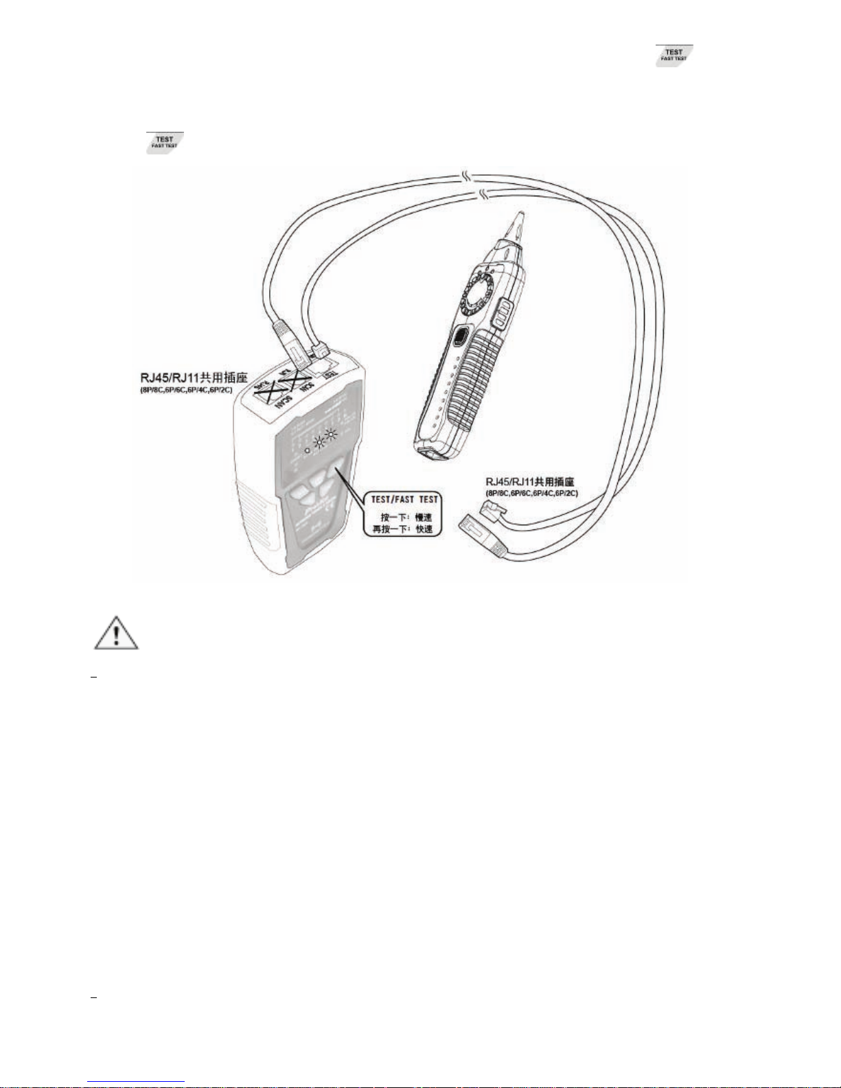
1. 將待測線插入音頻發射器RJ45/RJ11 TEST插座,另一段插入接收器插座。
2. 按下「
」電源開/關鍵,「POWER/BAT LOW」紅色指示燈亮起,再按
「
」功能鍵,「TEST」功能綠色指示燈慢速閃爍,線序/故障測試的功
Page 27
26
能啟動,線對(Cable Map)綠色LED開始慢速掃描顯示。再按一下「 」功
能鍵,「TEST」線序/故障功能綠色指示燈快速閃爍,表示線序/故障快速測
試功能啟動,線對表(Cable Map)的綠色LED開始快速掃描顯示。再按一下
「
」功能鍵,「TEST」功能指示燈熄滅,回到待機狀態。
(圖三) 線對表(Cable Map)測試
注意
•
線對表(Cable Map)測試時,LED慢速掃描顯示間隔約1秒鐘,LED快速掃描
顯示間隔約0.5秒鐘,每次由1~8、G順序掃描顯示。如果遇到2條空線時,會
有間歇2秒的現象,依此類推。
• 線對表(Cable Map)測試前,如有必要,可依前面所述方式,使用“尋線”的
方法,先查找另一端正確的連接器或連接線。
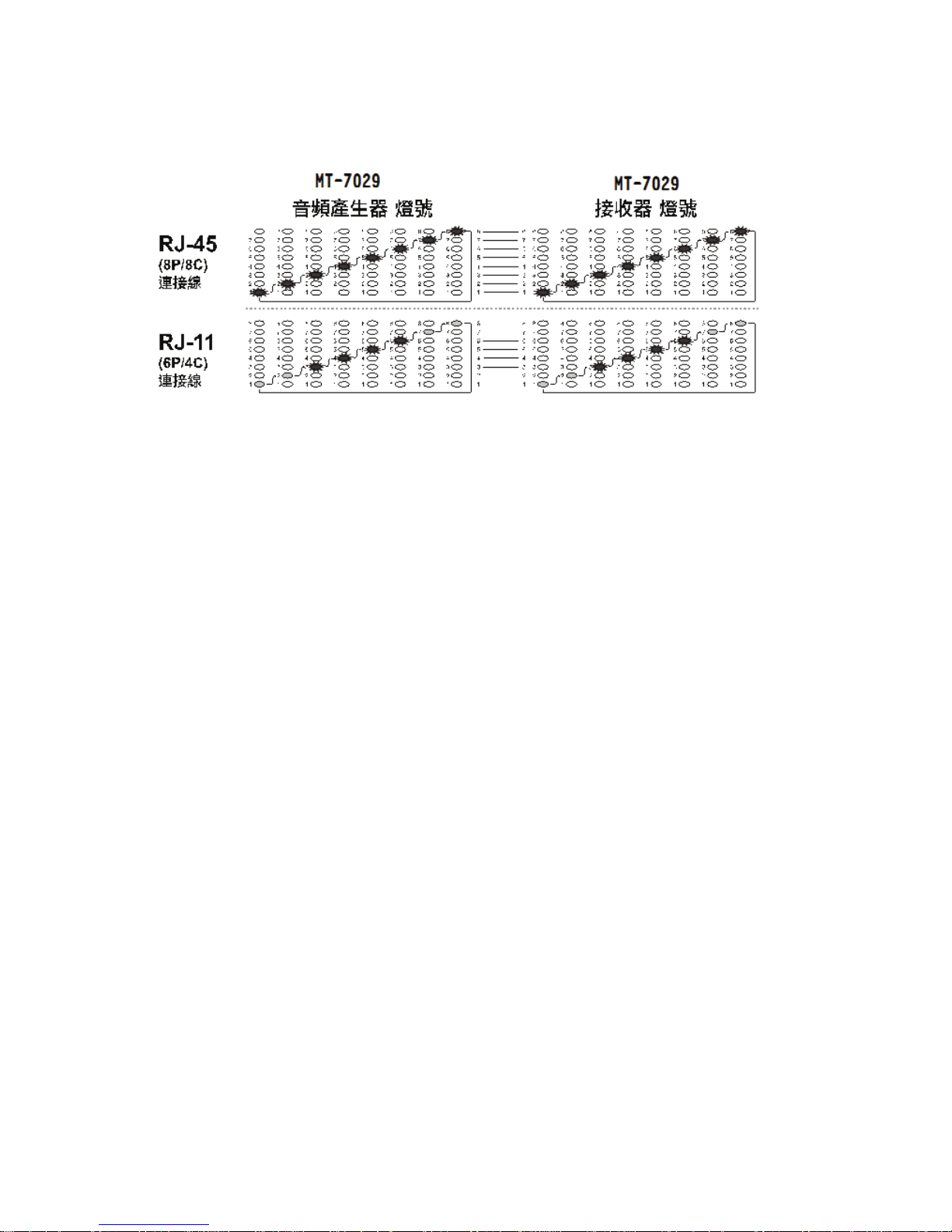
3. MT-7029音頻發射器和MT-7029接收器上的LED輸出,不同線材的線對表
(Cable Map)顯示方式如下:
• RJ45(8P/8C)的LED燈號顯示:MT-7029音頻發射器的線對表(Cable
Map)LED,每1秒由1~8、G的順序,依次顯示;並依接線順序,對應MT-7029
接收器上的線對表(Cable Map)LED同步顯示。(如圖四)
•
RJ11(6P/6C、6P/4C、6P/2C)的LED燈號顯示:MT-7029音頻發射器的線對表
(Cable Map)LED,6P/6C每1秒由2~7的順序;6P/4C每1秒由3~6的順序;6P/2C
Page 28
27
每1秒由4~5的順序),逐步顯示;並依接線順序,對應MT-7029接收器上的線
對表(Cable Map)LED同步顯示。如果遇到空線時,會有顯示間歇的現象。(如
圖四)
(圖四) 不同線材的線對表(Cable Map)
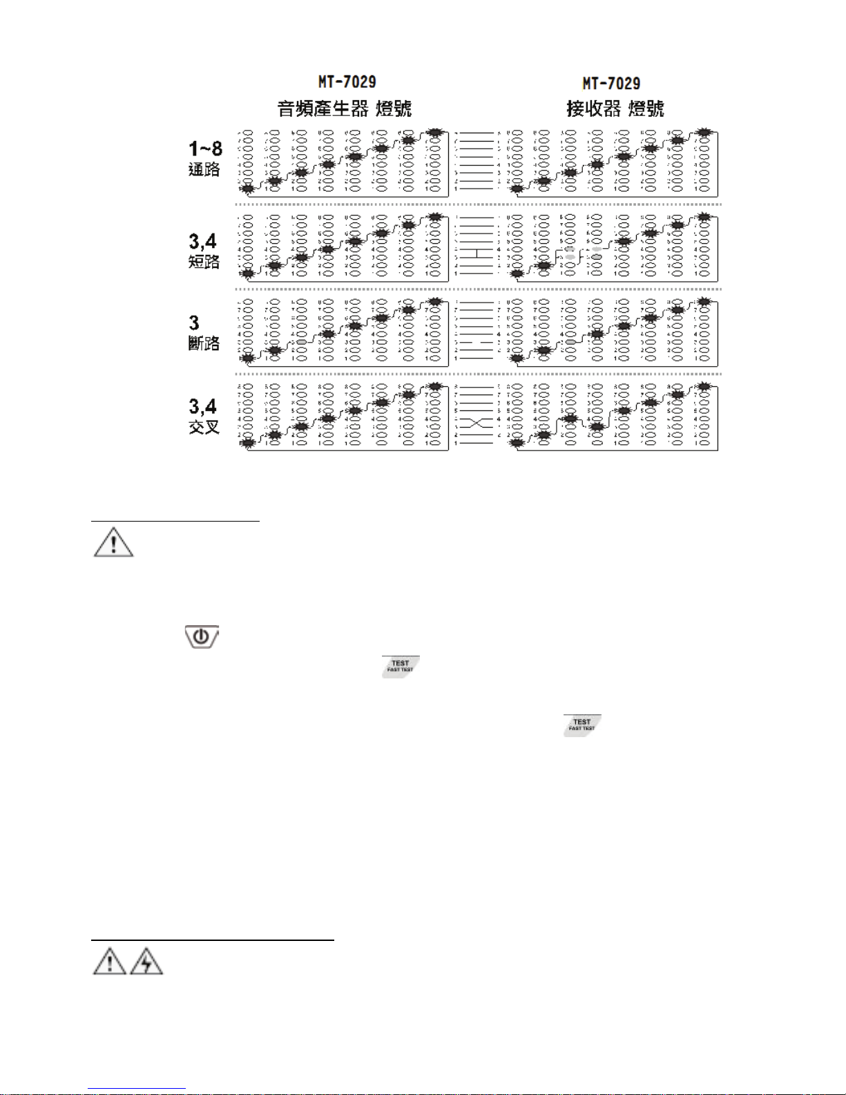
MT-7029音頻發射器和MT-7029接收器上的線對表(Cable Map)LED顯示,通路、短
路、斷路、交叉表示的方式如下:
• 「通路」的LED燈號顯示:MT-7029音頻發射器和接收器對應的1~8、 G個
LED燈同步點亮顯示。(如圖五)
• 「短路」的LED燈號顯示:MT-7029音頻發射器的LED依序亮燈,接收器上
的LED,第3個和第4個LED同時點亮,但亮度較暗(如圖五)表示網絡跳線
3&4pin短路。(若同時短路跳線超過3根,因電流供電不足,對應接收器上
的LED亮度會更暗或不亮)
• 「斷路」的LED燈號顯示:MT-7029音頻發射器和接收器對應的第3個LED均
不亮,表示網絡跳線第3pin斷開。(如圖五)
• 「交叉」的LED燈號顯示:MT-7029音頻發射器的LED第3、4個LED依序點
亮,對應MT-7029接收器上的LED,第3、4個LED按照4、3的順序依次顯示,
表示網絡跳線第3、4pin線序接反。(如圖五)
4. 依照MT-7029音頻發射器和MT-7029接收器上的線對表(Cable Map) LED輸
出,反復測試;並以LED顯示的線對表(Cable Map)確認接線順序的正確性。
Page 29
28
(圖五) 通路、短路、斷路、交叉
工作中的網路檢測:
注意:此測試方法只能測試網線路通斷,不能檢測交叉或短路。
1. 將MT-7029音頻發射器妥善連接RJ45(8P/8C)網路線或插座、另一端連接在正
在工作的網路交換機上。
2. 按下「
」電源開/關鍵,「POWER/BAT LOW」紅色電源指示燈亮起,
再按下MT-7029音頻發射器的「
」線序/故障功能鍵,「TEST」線序/故
障功能綠色指示燈慢速閃爍,表示線序/故障慢速測試功能啟動,線對表
(Cable Map)的綠色LED開始慢速掃描顯示。再按一下「
」線序/故障功能
鍵後,「TEST」線序/故障功能綠色指示燈快速閃爍時,表示線序/故障快速
測試功能啟動,線對表(Cable Map)的綠色LED開始快速掃描顯示。再按一下
此功能鍵,「TEST」線序/故障功能綠色指示燈熄滅後,表示回到待機狀態。
3. 當MT-7029音頻發射器上的「1~8、G」測試結果指示燈,按先後順序逐一點
亮時,表示網路線1~8、G全部連通,如有燈號未亮,代表線路故障。
同軸電纜線和電線連通測試:
警告:測試前,請先將電源關閉。
當你需要確認同軸電纜線或電線連通是否有接觸不良時,請依照下列步驟進行:
1. 先將MT-7029音頻發射器的黑色鱷魚夾,確認與待測電纜的一端接頭、金屬
Page 30

29
部分連接妥善,再將紅色鱷魚夾,與待測電纜的另一端接頭、金屬部分連
接妥善。
2. 按下「
」電源開/關鍵,「POWER/BAT LOW」紅色電源指示燈亮起,
打開電源。再按下MT-7029音頻發射器的「
」短路/導通功能鍵後,當「Ω」
短路/導通功能綠色指示燈亮起時,表示短路/導通測試的功能啟動。再按一
下此功能鍵後,當「Ω」短路/導通功能綠色指示燈熄滅後,表示回到待機
狀態。
3. 當「SHORT」短路測試結果紅色指示燈亮起時,表示連通(阻抗<300Ω)。當
指示燈不亮時,表示無連通,或是遮蔽不良和連通不良(阻抗>300Ω)。
電話正負極性測試:
當你需要確認電話線路的正負極性時,請依照下列步驟進行:
1. 先將MT-7029音頻發射器的紅、黑色鱷魚夾,分別與待測電話線路的連接線
或插座或接線板的兩端連接妥善。
2. 按下「
」電源開/關鍵,「POWER/BAT LOW」紅色電源指示燈亮起。
再按下MT-7029音頻發射器的「
」電話極性功能鍵後,當「POL」電話
極性功能指示燈亮起時,表示電話正/負極性測試的功能啟動。
3. 「POL-/G,POL+/R」電話極性測試結果指示燈,是一個紅/綠雙色LED指
示燈:
• 紅色指示燈亮或閃爍時,代表紅色鱷魚夾端為電話局線的”十”極,黑
色鱷魚夾端為電話局線的”一”極。
• 綠色指示燈亮或閃爍時,代表紅色鱷魚夾端為電話局線的”一”極,黑
色鱷魚夾端為電話局線的”十”極。
• 當指示燈不亮時,代表電話線路無供電或是線路故障。
電話狀態指示測試(只能使用在模擬電話線路上,不能在數位電話上使用):
當你需要確認電話線路的工作狀態時,請依照下列步驟進行:
1. 先將MT-7029音頻發射器的紅、黑色鱷魚夾,分別與待測電話線路的連接線
或插座或接線板的兩端連接妥善。
2. 按下「
」電源開/關鍵,「POWER/BAT LOW」紅色電源指示燈亮起,
打開電源。再連續兩次按下MT-7029音頻發射器的「
」電話極性功能鍵
後,當「TEL」電話狀態指示燈亮起時,表示電話狀態測試的功能啟動。
3. 測試電話線狀態時,機器會同步顯示其電話極性 :
•
當CONT紅色指示燈亮起時,代表紅色鱷魚夾端為電話局線的”十”
極,黑色鱷魚夾端為電話局線的”一”極。
•
當CONT綠色指示燈亮起時,代表紅色鱷魚夾端為電話局線的”一”
Page 31
30
極,黑色鱷魚夾端為電話局線的”十”極。
•
當CONT指示燈不亮時,代表電話線路無供電或是線路故障。
4. 「CONT」電話狀態測試結果指示燈,是一個紅/綠雙色LED指示燈:
• 當CONT 指示燈亮紅色或綠色時,表示待機狀態。
• 當CONT 指示燈不亮或變暗時,表示占線狀態。
• 當CONT 指示燈閃爍時,表示響鈴未接聽狀態。
NCV非接觸驗電:
注意:
此項測試功能可以被廣泛應用在定位、分離、導通、查找、線對表(Cable Map)
測試前,確認被測線路中是否有交流電壓,除可確保人身安全.避免觸電外,也
可以保護MT-7029音訊網路測試器,不被交流電壓損壞!
1. 將4段功能選擇開關,撥切至「NCV」檔 位 後,電 源 指 示 燈 亮起,表 示「NCV」
非接觸驗電測試的功能啟動。
2. 將MT-7029接收器的探頭靠近被測物,進行非接觸驗電(NCV)測試,當非接
觸驗電(NCV)指示燈快速閃爍、同時蜂鳴警報時,代表被測物具有90~1000V
交流電壓。當指示燈不亮、無蜂鳴警報時,代表被測物的交流電壓低於90V
或是沒有交流電壓。
維護與簡易故障排除:
維護:
警告
為避免可能發生的電擊或人體傷害,維護前,應關機並斷開所有測試導線的連
接。
小心
為避免損壞機殼,不要使用溶劑或磨蝕性去污粉。
用柔性軟布沾水後擰乾、或柔性軟布沾柔性皂液後擰乾,輕輕的擦拭機殼。
簡易故障排除:
故障 排除
電池電力不足:檢查音頻發射器和接收器的電池,如電壓
低於 6.5V,需更換電池。
接收器無法探測音頻
發射器的信號
接收器檔位不正確:請撥至 SCAN 檔或 LED 照明檔,其
他檔位不能探測 SCAN 信號。
Page 32
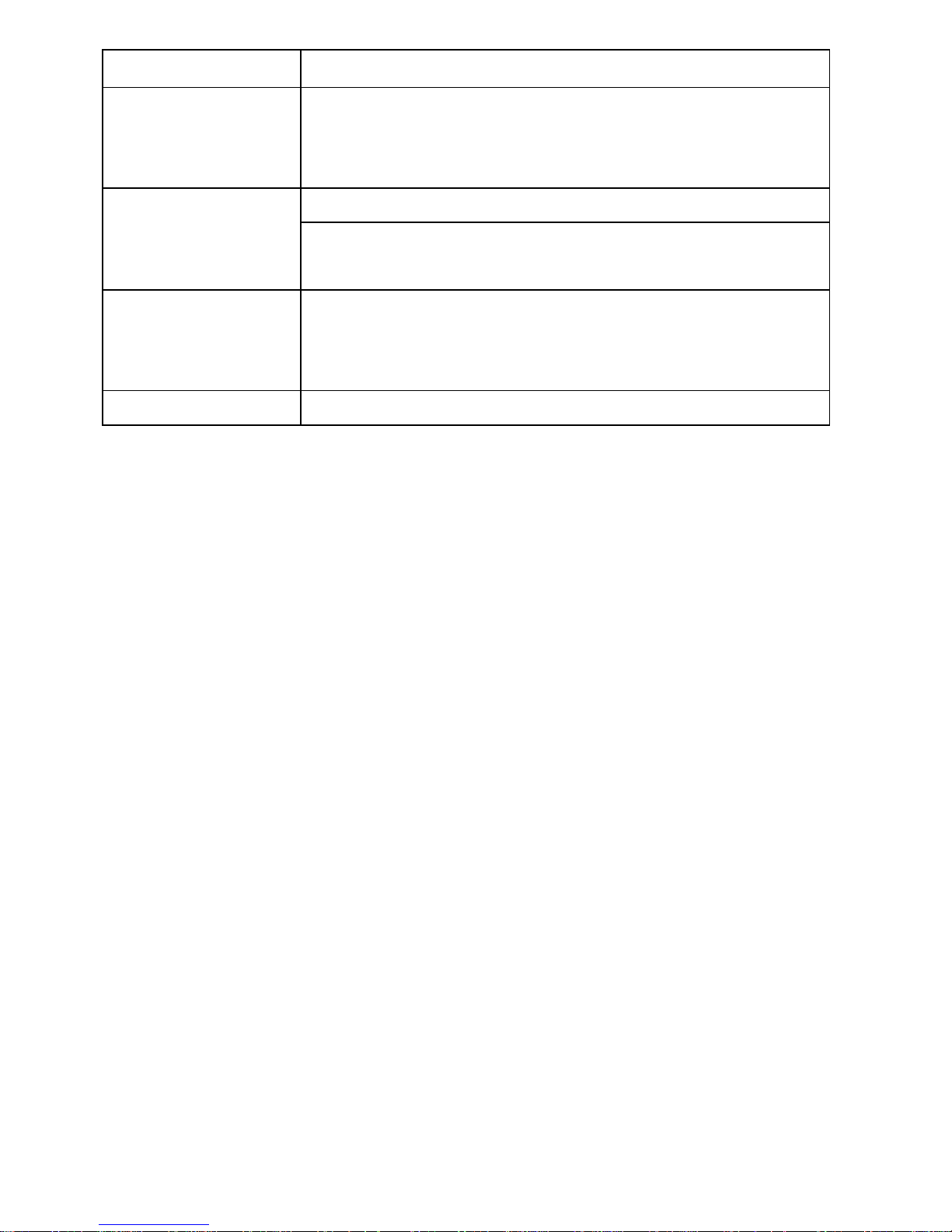
31
儀器故障:返回經銷商維修。
活電下測試電話局
線,接收器無法探測
音頻發射器的信號
可能是電話局線信號頻率,與本音頻發射器的信號衝突,
請關閉電話交換機。
LED 指示燈損壞:返回經銷商維修
線序/故障測試結果
顯示不正確
網路線或電話線接觸不良:請將網路線或電話線,重新插
入 RJ45/RJ11 共用插座。
NCV 無法測試
將開關撥到 SCAN 檔,按 SCAN 鍵,如 SCAN 指示燈閃亮
明顯,則表明電池有電,如微弱閃亮或不亮,則電池電量
低,需更換電池
其他功能異常 儀器故障:返回經銷商維修
Page 33
32
MT-7029 抗干扰型音频网络 PoE 查线器
使用说明书
感谢您购买和使用 Pro’sKit MT-7029 抗干扰型音频网络 PoE 查线器,使用本产
品前请仔细阅读说明书,阅读后请妥善保存,以备日后查阅。
特点概述:
MT-7029是一款采用最新数字电路技术,能使用户在查找线缆时避免电磁干扰,
排除噪音,更轻松的查找目标线路;诊断RJ45网络线(UTP、STP、Cat 5、Cat 5 e、
Cat 6)、RJ11/12电话线(Cat. 3 (2/4/6 pin)的通路、短路、断路、交叉等状况,并提
供STP & PoE交换机线缆的查找与定位;确认电话线的状态&接线极性;测试一
般电线连接的状况。配有鳄鱼夹,可应用于测试同轴电缆线、一般电线和电信/
网络接线板。
适用于电信、网络通讯、监控、有线电视等室内、外布线施工或维护等工程使
用。
产品规格:
MT-7029 音频发射器 规格
音频发射频率 130KHz
音频最大测试距离 ≧3 公里
线序/故障最大测试距离 300 米
最大工作电流 ≦70mA
音色 单音调
可测试连接阜
TEST 插座: 提供 RJ45(8 pin)/RJ11(6 pin)线对测试
RJ45 SCAN 插座: 提供 RJ45(8pin)音频寻线使用
RJ11 SCAN 插座: 提供 RJ11(6P/6C/4C/2C)音频寻线
使用。
适用电缆线
RJ45 网络线 Cat 5、5e、6(UTP/STP)、RJ11/12 电话
线 Cat 3 (6P/2C/4C/6C)
功能选择
5 个按式开关(电源、寻线 SCAN/PoE SCAN、线对
TEST/FAST TEST、短路/导通 Ω、电话极性/电话
线状态 POL/TEL)
短路/导通测试
1 个 LED 显示 (线路≦300Ω),同轴电缆线和一般
单芯/多芯绞线用鳄鱼夹线测试
输出信号电压 8Vp-p
线序/故障指示 8个 LED,快/慢双速测试
网络线带遮蔽指示灯 1个 LED
电话线 正/负极性、状态指示 1个双色 LED
Page 34
33
电信设备和路由器活电测试 有
电压保护 DC 48V
自动关机 约 1 小时
电池低压指示 6.5V (电源指示灯闪烁)
电池 DC 9.0V (NEDA 1604/ 6F22 DC9V ×1pcs)
外观尺寸 (长×宽×高) 138×80×35 mm
重量 140 公克
MT-7029 接收器 规格
音频接收频率 130KHz
最大工作电流 ≦115mA
可测试连接阜 RJ45(8 pin)/RJ11(6 pin) 共享插座
功能选择
4 段滑动开关(LED 照明、非接触验电 NCV、关机
OFF、寻线 SCAN)
耳机座 1个
信号强弱指示 1个双色 LED & 蜂鸣器
线序/故障指示 8个 LED
网络线带遮蔽指示 1个 LED
非接触验电(NCV)指示 1个 LED (交流 90~1000V)
工作照明 1个 LED
电源指示 1个 LED
电池 DC 9.0V (NEDA 1604/ 6F22 DC9V ×1pcs)
外观尺寸 (长×宽×高) 203×50×32 mm
重量 95公克
配件
RJ45(8pin)网络线、RJ11(6pin)电话线、RJ11(6pin)
对鳄鱼夹线、耳机、携存袋、使用手册
使用安全
• 请勿连接超过DC 48V的活电线路,以免造成仪器损坏。
• 请勿使用破损的测试器或测试线,使用前请检查机壳和测试线是否有破损。
• 测试电话电路时,请先将不使用的测试线和连接器从测试器上移除。
• 除非要更换电池,否则不得打开机壳;其中没有任何用户可维修的零件。
• 更换电池前请先关机!并将测试线移除。
• 请使用9V电池并正确安装在机壳内以提供电源。
• 如果不遵照指定方式使用本设备,则可能影响本产品提供的保护。
MT-7029 部件名称
任何超过DC 48V的活电的线路,不可接入本仪器任何测试插座,以免造成
Page 35
34
仪器损坏。
MT-7029 音频发射器 外观图
1.「TEST」:RJ45(8 pin)/RJ11(6/4/2 pin)对线测试插座
2.「SCAN」:RJ11 (6 pin)插座
3.「SCAN」:RJ45插座
4.「SHORT」:短路测试结果指示灯
5.「Ω」:短路/导通功能指示灯
6.「SCAN」:寻线功能指示灯
7.「PoE SCAN」:寻线功能指示灯
8.「POWER/BAT LOW」:电源指示灯
9.「1~8、G」:测试结果指示灯
10.「TEST」:线序/故障功能指示灯
11.「POL-/G,POL+
/R」:电话
极性测试结果指示灯:
12.「POL」:电话极性功能指示灯:
13.「CONT」:电话线路状态及极性测试结果指示灯
14.「TEL」:电话线路状态指示灯
15.「
」:SCAN/PoE SCAN网络&PoE寻线功能键:
16.「
」:短路/导通功能键
17.「
」:电源开/关键
18.「
」:TEST/FAST TEST快/慢线序/故障功能键:
19.「
」:POL/TEL电话极性&电话线状态功能键:
20.电池盖。
Page 36
35
MT-7029 接收器 外观图
1.音频信号探头
2.LED照明灯
3.电源指示灯
4.非接触验电(NCV)指示灯
5.信号强弱指示灯
6.音量旋钮
7.ø3.5mm耳机座
8.4 段功能开关
9.喇叭
10.「
」寻线功能键
11.「1~8、G」测试结果指示灯
12.RJ45(8 pin)/RJ11(6/4/2 pin)测试插座
13.电池盖。
使用音频信号查找、分离电线:
使用MT-7029查找线路时,能定位、分离、查找双绞线(UTP/STP Cat 5、Cat 5e、
Cat 6)、电话线(Cat 3),搭配跳接线可以测试RJ45/RJ11插座的接线,搭配鳄鱼夹
连接线,可测试同轴电缆线、一般电线和各种接线板。
警告
Page 37

36
• MT-7029不可以使用在超过DC 48V的带电线路上,操作前应确认关闭所有电
源。
• RJ45网络线寻线时,请使用RJ45 SCAN插座。RJ11(6P/6C/4C/2C)电话线寻线
时,请使用RJ11 SCAN插座。使用RJ11(6 pin)插座,搭配鳄鱼夹连接线,可
测试同轴电缆线、一般电线和各种接线板。
注意
• MT-7029的音频信号,通过电路机板或分岔线路或整捆电线(绞线)时,会有
相互感应传递和信号强度的衰减的现象,且无法穿透金属配线管。
• 在使用MT-7029前,请先将MT-7029 音讯发射器的黑色鳄鱼夹进行接地作
业。
• 在使用MT-7029音频网络测试器耳机进行查线时,请将探头远离耳机线,避
免产生共鸣影响查线效果。
• 使用音频查线时,接收器有可能受到其他设备谐波的影响,接收器寻线声
音变小或中断,请移动至讯号声较强的地方进行查线。
• 由於各家PoE单端口网络电源供应器設備的差異,可能导致接收器信号间
歇、下降或中断,请移动到更好的信号接收位置
• 使用PoE scan功能进行查线时, 由于各家PoE设备的差异,有些可能会消耗较
大电流, 导致电池电力消耗较快,此为正常现象。
查找电线
当你需要查找电线布线位置或查找电线断路位置时,请依照下列步骤(如图一)
进行:
1. 如(图一)所示,先将MT-7029音频发射器的黑色鳄鱼夹接地,再将红色鳄鱼
夹与待测线路的连接线或插座或接线板连接妥善。
2. 如(图一)所示,按下「
」电源开/关键,「POWER/BAT LOW」红色电源
指示灯亮起,打开电源。
SCAN:按下「
」寻线功能键后,当「SCAN」寻线功能红色指示灯亮
起时,表示寻线信号发射功能启动,SCAN功能适用于带电的网络交换机或
不带电的跳线寻线。
PoE SCAN:再次按下「
」寻线功能键,PoE SCAN灯亮起,表示PoE寻
线测试的功能启动,PoE SCAN功能适用于带电的PoE交换机与网络交换机适
用。(如果在寻线过程中接收器接收目标线声音微弱,可能为跳线未连接
PoE交换机/网络交换机或者跳线内部断开,请切换回SCAN进行查找)再次
按下「
」寻线功能键,指示灯熄灭,停止发射信号。
Page 38
37
3. 如(图一)所示,将接收器4段功能开关拨到SCAN或LED照明档,中间红色电
源指示灯亮起,按下接收器中间的「
」寻线功能键,寻线测试的功能
启动,可进行寻线;放开「
」寻线功能键,寻线测试的功能关闭。未
插上耳机前喇叭有声音输出,插上耳机后则喇叭无声音输出,声音由耳机
输出。
4. 使用接收器寻线时 将音量旋钮转到最大,沿着塑料配线管、走线架、接线
板或墙壁,查找布线线路的大致位置。接近时,接收器的喇叭响起音频信
号,喇叭声音越大,表示信号越强;同时信号强弱指示灯LED由红色变为蓝
色,指示灯明暗程度会随信号强度改变,当此蓝色指示灯越亮,表示信号
越强。
5. 旋转音量旋钮,调整接收信号灵敏度,控制音量由大到小,精确查找到目
标电线。
(图一) 查找电线
分离电线
当你需要寻找捆绑在一起的电缆其中一条电线,或多芯电缆中的其中一条芯线
时,请依照前面查找电线的步骤(1.)到(4.)进行(如图一),然后再依照下列步骤(如
图二)继续进行:
1. 将电缆拨开约30~45cm长,采用二分法,将电缆的芯线概略分为左右各一半,
使用MT-7029接收器寻找目标芯线的位置,喇叭声音较大和LED灯比较亮(信
号较强)的一边,代表其中包含了你所要寻找的目标芯线。
2. 旋转音量旋钮,控制音量由大到小,则可以改变查找电线的灵敏度,将搜
寻位置由15cm缩小到0cm以内,精确找到目标芯线的位置。
3. 重复前面二分法的(1)、(2)步骤,则可轻易找到目标芯线。
注意
如果不能正确分辨两导线电缆上的音频信号,可能因交换机的原因,寻线时存
在两根导线或多根导线同时有较强的音频信号或无法接收到音频信号,此时,
Page 39
38
建议关闭交换机或依次拔掉网络线进行寻线;如仍旧无法接收到音频信号,可
能为导线断开,可以用TEST对线功能或Ω通断功能检查导线是否连接正常。
(图二) 分离电线
线对表(Cable Map)测试:
可以使用MT-7029音频发射器”TEST”两用插座,配合MT-7029接收器RJ45/RJ11
两用插座,测试RJ45网络线和RJ11电话线的线对表(Cable Map)。搭配跳接线可以
测试RJ45/RJ11插座的线对表(Cable Map)。线对表(Cable Map)的功能可查找各种电
缆布在线常见的:通路、短路、断路、交叉的情况。
注意!
进行RJ45或RJ11线对表(Cable Map)测试时,RJ45网络线/RJ11电话线只能插入音频
发射器的”TEST”两用插座,不可使用RJ45 SCAN或 RJ11 SCAN插座。
1. 将待测线插入音频发射器RJ45/RJ11 TEST插座,另一段插入接收器插座。
2. 按下「
」电源开/关键,「POWER/BAT LOW」红色指示灯亮起,再按
「
」功能键,「TEST」功能绿色指示灯慢速闪烁,线序/故障测试的功
能启动,线对(Cable Map)绿色LED开始慢速扫描显示。再单击「
」功能
键,「TEST」线序/故障功能绿色指示灯快速闪烁,表示线序/故障快速测试
功能启动,线对表(Cable Map)的绿色LED开始快速扫描显示。再单击「
」
功能键,「TEST」功能指示灯熄灭,回到待机状态。
Page 40
39
(图三) 线对表(Cable Map)测试
注意
•
线对表(Cable Map)测试时,LED慢速扫描显示间隔约1秒钟,LED快速扫描
显示间隔约0.5秒钟,每次由1~8、G顺序扫描显示。如果遇到2条空线时,会
有间歇2秒的现象,依此类推。
• 线对表(Cable Map)测试前,如有必要,可依前面所述方式,使用“寻线”的
方法,先查找另一端正确的连接器或连接线。
3. MT-7029音频发射器和MT-7029接收器上的LED输出,不同线材的线对表
(Cable Map)显示方式如下:
• RJ45(8P/8C)的LED灯号显示:MT-7029音频发射器的线对表(Cable Map)LED,
每1秒由1~8、G的顺序,依次显示;并依接线顺序,对应MT-7029接收器上
的线对表(Cable Map)LED同步显示。(如图四)
•
RJ11(6P/6C、6P/4C、6P/2C)的LED灯号显示:MT-7029音频发射器的线对表
(Cable Map)LED,6P/6C每1秒由2~7的顺序;6P/4C每1秒由3~6的顺序;6P/2C
每1秒由4~5的顺序),逐步显示;并依接线顺序,对应MT-7029接收器上的线
对表(Cable Map)LED同步显示。如果遇到空线时,会有显示间歇的现象。(如
图四)
Page 41
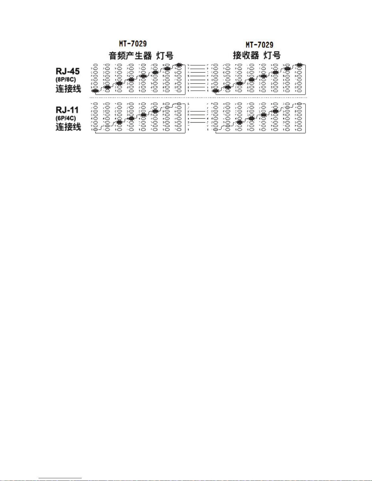
40
(图四) 不同线材的线对表(Cable Map)
MT-7029音频发射器和MT-7029接收器上的线对表(Cable Map)LED显示,通路、短
路、断路、交叉表示的方式如下:
• 「通路」的LED灯号显示:MT-7029音频发射器和接收器对应的1~8、 G个
LED灯同步点亮显示。(如图五)
• 「短路」的LED灯号显示:MT-7029音频发射器的LED依序亮灯,接收器上
的LED,第3个和第4个LED同时点亮,但亮度较暗(如图五)表示网络跳线
3&4pin短路。(若同时短路跳线超过3根,因电流供电不足,对应接收器上
的LED亮度会更暗或不亮)
• 「断路」的LED灯号显示:MT-7029音频发射器和接收器对应的第3个LED
均不亮,表示网络跳线第3pin断开。(如图五)
• 「交叉」的LED灯号显示:MT-7029音频发射器的LED第3、4个LED依序点
亮,对应MT-7029接收器上的LED,第3、4个LED按照4、3的顺序依
次显示,
表示网络跳线第3、4pin线序接反。(如图五)
4. 依照MT-7029音频发射器和MT-7029接收器上的线对表(Cable Map) LED输
出,反复测试;并以LED显示的线对表(Cable Map)确认接线顺序的正确性。
Page 42
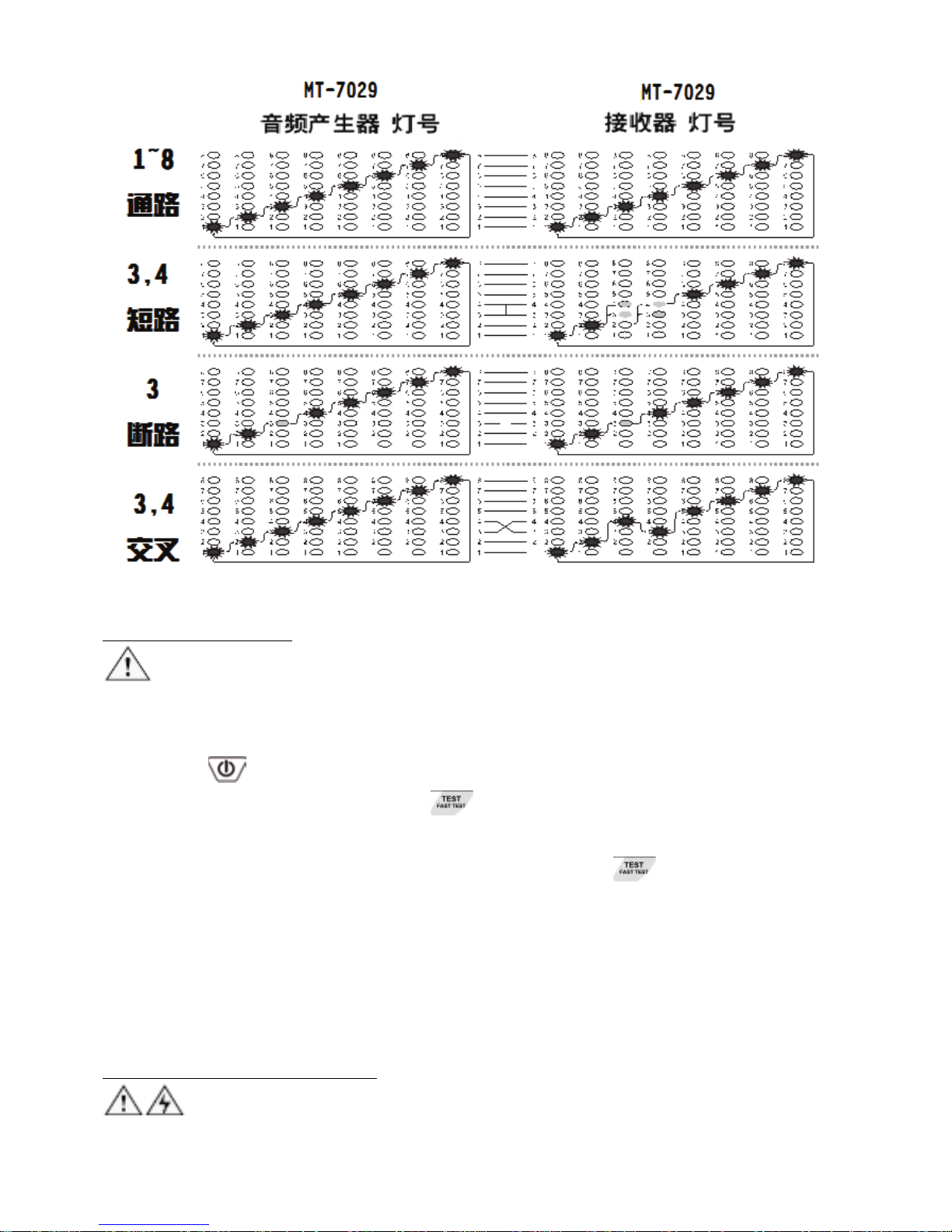
41
(图五) 通路、短路、断路、交叉
工作中的网络检测:
注意:此测试方法只能测试网线路通断,不能检测交叉或短路。
1. 将MT-7029音频发射器妥善连接RJ45(8P/8C)网络线或插座、另一端连接在正
在工作的网络交换机上。
2. 按下「
」电源开/关键,「POWER/BAT LOW」红色电源指示灯亮起,
再按下MT-7029音频发射器的「
」线序/故障功能键,「TEST」线序/故
障功能绿色指示灯慢速闪烁,表示线序/故障慢速测试功能启动,线对表
(Cable Map)的绿色LED开始慢速扫描显示。再单击「
」线序/故障功能键
后,「TEST」线序/故障功能绿色指示灯快速闪烁时,表示线序/故障快速测
试功能启动,线对表(Cable Map)的绿色LED开始快速扫描显示。再单击此功
能键,「TEST」线序/故障功能绿色指示灯熄灭后,表示回到待机状态。
3. 当MT-7029音频发射器上的「1~8、G」测试结果指示灯,按先后顺序逐一点
亮时,表示网络线1~8、G全部连通,如有灯号未亮,代表线路故障。
同轴电缆线和电线连通测试:
警告:测试前,请先将电源关闭。
当你需要确认同轴电缆线或电线连通是否有接触不良时,请依照下列步骤进行:
Page 43

42
1. 先将MT-7029音频发射器的黑色鳄鱼夹,确认与待测电缆的一端接头、金属
部分连接妥善,再将红色鳄鱼夹,与待测电缆的另一端接头、金属部分连
接妥善。
2. 按下「
」电源开/关键,「POWER/BAT LOW」红色电源指示灯亮起,
打开电源。再按下MT-7029音频发射器的「
」短路/导通功能键后,当「Ω」
短路/导通功能绿色指示灯亮起时,表示短路/导通测试的功能启动。再单击
此功能键后,当「Ω」短路/导通功能绿色指示灯熄灭后,表示回到待机状
态。
3. 当「SHORT」短路测试结果红色指示灯亮起时,表示连通(阻抗<300Ω)。当
指示灯不亮时,表示无连通,或是遮蔽不良和连通不良(阻抗>300Ω)。
电话正负极性测试:
当你需要确认电话线路的正负极性时,请依照下列步骤进行:
1. 先将MT-7029音频发射器的红、黑色鳄鱼夹,分别与待测电话线路的连接线
或插座或接线板的两端连接妥善。
2. 按下「
」电源开/关键,「POWER/BAT LOW」红色电源指示灯亮起。
再按下MT-7029音频发射器的「
」电话极性功能键后,当「POL」电话
极性功能指示灯亮起时,表示电话正/负极性测试的功能启动。
3. 「POL-/G,POL+/R」电话极性测试结果指示灯,是一个红/绿双色LED指
示灯:
• 红色指示灯亮或闪烁时,代表红色鳄鱼夹端为电话局线的”十”极,黑
色鳄鱼夹端为电话局线的”一”极。
• 绿色指示灯亮或闪烁时,代表红色鳄鱼夹端为电话局线的”一”极,黑
色鳄鱼夹端为电话局线的”十”极。
• 当指示灯不亮时,代表电话线路无供电或是线路故障。
电话状态指示测试(只能使用在仿真电话线路上,不能在数字电话上使用):
当你需要确认电话线路的工作状态时,请依照下列步骤进行:
1. 先将MT-7029音频发射器的红、黑色鳄鱼夹,分别与待测电话线路的连接线
或插座或接线板的两端连接妥善。
2. 按下「
」电源开/关键,「POWER/BAT LOW」红色电源指示灯亮起,
打开电源。再连续两次按下MT-7029音频发射器的「
」电话极性功能键
后,当「TEL」电话状态指示灯亮起时,表示电话状态测试的功能启动。
3. 测试电话线状态时,机器会同步显示其电话极性 :
•
当CONT红色指示灯亮起时,代表红色鳄鱼夹端为电话局线的”十”极,
黑色鳄鱼夹端为电话局线的”一”极。
Page 44
43
• 当CONT绿色指示灯亮起时,代表红色鳄鱼夹端为电话局线的”一”极,
黑色鳄鱼夹端为电话局线的”十”极。
•
当CONT指示灯不亮时,代表电话线路无供电或是线路故障。
4. 「CONT」电话状态测试结果指示灯,是一个红/绿双色LED指示灯:
• 当CONT 指示灯亮红色或绿色时,表示待机状态。
• 当CONT 指示灯不亮或变暗时,表示占线状态。
• 当CONT 指示灯闪烁时,表示响铃未接听状态。
NCV非接触验电:
注意:
此项测试功能可以被广泛应用在定位、分离、导通、查找、线对表(Cable Map)
测试前,确认被测线路中是否有交流电压,除可确保人身安全.避免触电外,也
可以保护MT-7029音频网络测试器,不被交流电压损坏!
1. 将4段功能选择开关,拨切至「NCV」档位后,电源指示灯亮起,表示「NCV」
非接触验电测试的功能启动。
2. 将MT-7029接收器的探头靠近被测物,进行非接触验电(NCV)测试,当非接
触验电(NCV)指示灯快速闪烁、同时蜂鸣警报时,代表被测物具有90~1000V
交流电压。当指示灯不亮、无蜂鸣警报时,代表被测物的交流电压低于90V
或是没有交流电压。
维护与简易故障排除:
维护:
警告
为避免可能发生的电击或人体伤害,维护前,应关机并断开所有测试导线的连
接。
小心
为避免损坏机壳,不要使用溶剂或磨蚀性去污粉。
用柔性软布沾水后拧干、或柔性软布沾柔性皂液后拧干,轻轻的擦拭机壳。
简易故障排除:
故障 排除
电池电力不足:检查音频发射器和接收器的电池,
如电压低于 6.5V,需更换电池。
接收器无法探测音频发射器
的信号
接收器档位不正确:请拨至 SCAN檔或 LED照明档,
其他档位不能探测 SCAN 信号。
Page 45
44
仪器故障:返回经销商维修。
活电下测试电话局线,接收器
无法探测音频发射器的信号
可能是电话局线信号频率,与本音频发射器的信号
冲突,请关闭电话交换机。
LED 指示灯损坏:返回经销商维修
线序/故障测试结果显示不正
确
网络线或电话线接触不良:请将网络线或电话线,
重新插入 RJ45/RJ11 共享插座。
NCV 无法测试
将开关拨到 SCAN 檔,按 SCAN 键,如 SCAN 指示
灯闪亮明显,则表明电池有电,如微弱闪亮或不亮,
则电池电量低,需更换电池
其他功能异常 仪器故障:返回经销商维修
Page 46

45
中国地区产品保固卡
购买日期
公司名称
联络电话
电子邮箱
联络地址
店章
产品型号 □ MT-7029-C
※ 在正常使用情况下,自原购买日起 12 个月免费维修保证(不含耗材、消
耗品)。
※ 产品保固卡需盖上店章、日期章,其保固效力始生效。
※ 本卡请妥善保存,如需维修服务时,请出示本卡以为证明。
※ 保固期满后,属调整、保养或是维修性质之服务,则酌收检修工时费用。
若有零件需更换,则零件费另计。
产品保固说明
保固期限内,如有下列情况者,维修中心则得酌收材料成本或修理费(由本
公司维修人员判定):
• 对产品表面的损伤,包括外壳裂缝或刮痕
• 因误用、疏忽、不当安装或测试,未经授权打开产品修理,修改产品或者
任何其它超出预期使用范围的原因所造成的损害
• 因事故、火灾、电力变化、其它危害,或自然灾难所造成的损害。
非服务保证内容:
• 机件本体外之消耗品:如电池...等消耗品
• 机件本体之外之附配件:如耳机麦克风,电源供应器,记忆卡,CD
等附配件。
超过保证期限之检修或服务,虽未更换零件,将依公司保固维修政策酌收服
务费。
制造商:宝工实业股份有限公司
地 址:台湾台北新北市新店区民权路 130 巷 7 号 5 楼
电 话:886-2-22183233
E-mail: [email protected]
生产商:上海宝工工具有限公司
地址:上海市浦东新区1365弄25号
原产地:中国 上海
销售公司:深圳畅联贸易有限公司
地址:深圳市福田区红荔西路上步工业区403栋东座5楼
电话:0755-83692415 传真:0755-83692143
400服务热线:400-1699-629
E-mail: [email protected]
Page 47

46
Page 48

47
寶工實業股份有限公司
PROKIT’S INDUSTRIES CO., LTD
http://www.prokits.com.tw
Email: [email protected]
©2017 Prokit’s Industries Co., LTD. All rights reserved 2017001(C)
 Loading...