

Page 1
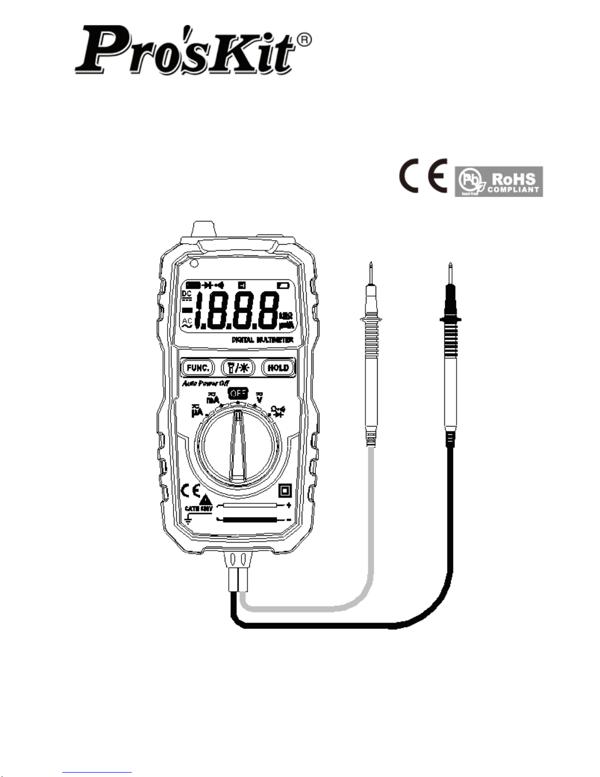
MT-1508
Pocket Auto Range Multimeter
User’s Manual
1st Edition,
©2015 Copyright by Prokit’s Industries Co., Ltd.
Page 2
1
THE STATEMENT
In accordance with the international copyright law, without permission and written consent,
please do not copy the contents of this manual in any form (including storage and retrieval or
translation into languages of other countries or regions). The manual is subject to change in
future edition without prior notice.
Caution
“Caution” mark refers to the condition and operation which may cause damage to the
instrument or equipment.
It requires that you must be careful during the execution of the operation. If you incorrectly
perform the operation or do not follow the procedure, it may damage the instrument or
equipment. In the circumstances that such conditions are not met or not fully understood, please
do not continue to perform any operation indicated by the caution mark.
Warning
“Warning” mark indicates the condition and operation which may cause danger to users.
It requires that you must pay attention during the execution of this operation. If incorrectly
perform the operation or do not follow the procedure, it may result in personal injury or
casualties. In the circumstances that such conditions are not met or not fully understood, please
do not continue to perform any operation indicated by the warning mark.
Before using the instrument, please read this manual carefully and pay attention to the
relevant safety warning information.
OVERVIEW
The instrument is a portable digital multimeter. It features stable performance, high accuracy,
low power consumption and novel structure, more safe and reliable. It’s an ideal measuring
instrument for users.
The instrument can measure DC voltage, AC voltage, DC current, AC current, resistance, diode
and connectivity, and non-contact voltage detection function.
This manual includes the relevant safety information, warning notices and so on, please read
the related contents carefully before using the instrument, and strictly follow all warnings and
precautions.
SAFETY INSTRUCTIONS
The instrument is designed and manufactured strictly in accordance with the safety standard
IEC61010 and in conformity with double insulation, over-voltage standard 600V CAT III and
pollution level 2 safety standards.
Please follow the manual to use the instrument, otherwise the protection function provided by
the instrument may be reduced or invalid.
SAFETY OPERATION
Warning
In order to avoid possible electric shock or personal injury, please abide by the following
specification:
Before using the instrument, please read the “Safety Instructions” in advance. Use the
instrument in strict accordance with the provisions”, otherwise the protection ability
provided by the instrument may be reduced or invalid.
Check the external shell first before using the instrument. Check whether there are any
cracks or defects on the plastic parts. Please carefully check the insulator near the input
terminal.
If the instrument is not working properly or is damaged, please do not use.
Do not touch the electrified body with more than 30V true effective value AC, 42V AC peak
or 60V DC.
The instrument shall be used according to the specified measurement category, voltage or
current rating.
When it shows low battery indication, please replace the battery in time to avoid any
Page 3
2
measurement error.
Please comply with local and national safety code. Wear personal protection equipment
(such as approved rubber gloves, masks and flame retardant clothes, etc.) to prevent
being damaged by electric shock and electric arc due to exposed hazardous live
conductor.
The voltage applied between input terminals or between each terminal and earth point
cannot exceed the specified ratings of the instrument.
Measure a known voltage to determine whether the instrument works properly.
When measuring, correct input terminal, function shift and range shift must be used.
Do not use the instrument around explosive gas, steam or in wet environment.
Do not use damaged probe. Check whether the insulation layer of the probe is damaged,
whether there’s any exposed metal or sign of wear. Check the continuity of the probe.
When measuring, please connect the zero line or the ground line first, then connect the live
wire; but when disconnecting, please cut off the live wire first, then disconnect the zero line
and ground line.
When measuring, please keep your fingers behind the finger protector of the probe.
Before opening the back cover of the instrument, please disconnect the probe from the
measured object.
Do not use the instrument in the environment of exceeding the measurement category
(CAT) rating of a single element with the lowest rating among the instrument, probe or
accessories.
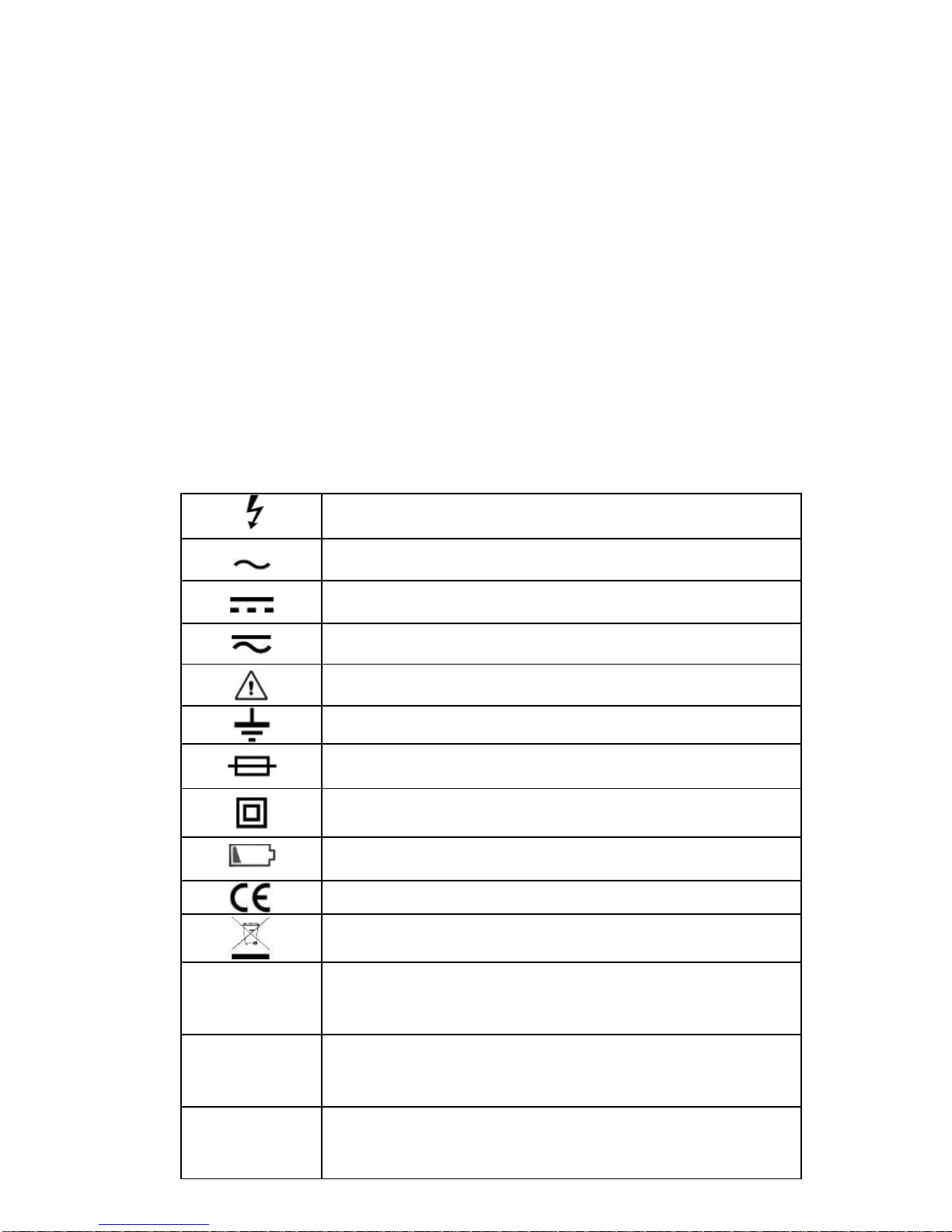
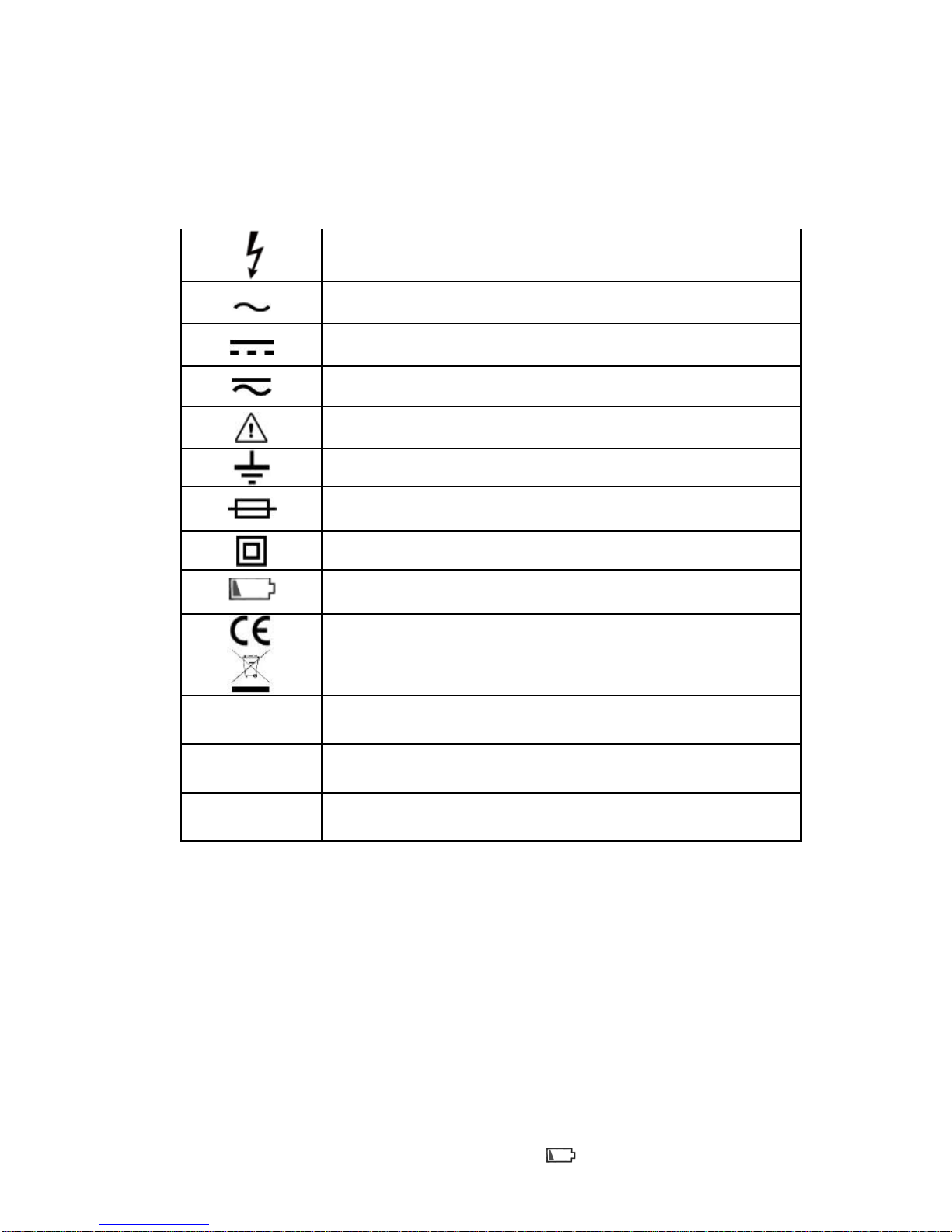
Electrical Symbols
High voltage warning
AC (Alternating current)
DC (Direct current)
AC or DC
Warning, important safety signs
Ground
Fuse
Equipment with double insulation or reinforced insulation
protection
Low battery
Conform with European Union standard
It shows that do not discard this electrical/electronic
product into household garbage.
CAT II
CAT II measurement is applicable for testing and
measuring circuits directly connecting to the supply point
(socket and similarities) of low voltage power supply.
CAT III
CAT III measurement is applicable for testing and
measuring circuits connecting to the distribution section
of building low voltage power supply.
CAT IV
CAT IV measurement is applicable for testing and
measuring circuits connecting to the distribution section
of building low voltage power supply.
Page 4
3
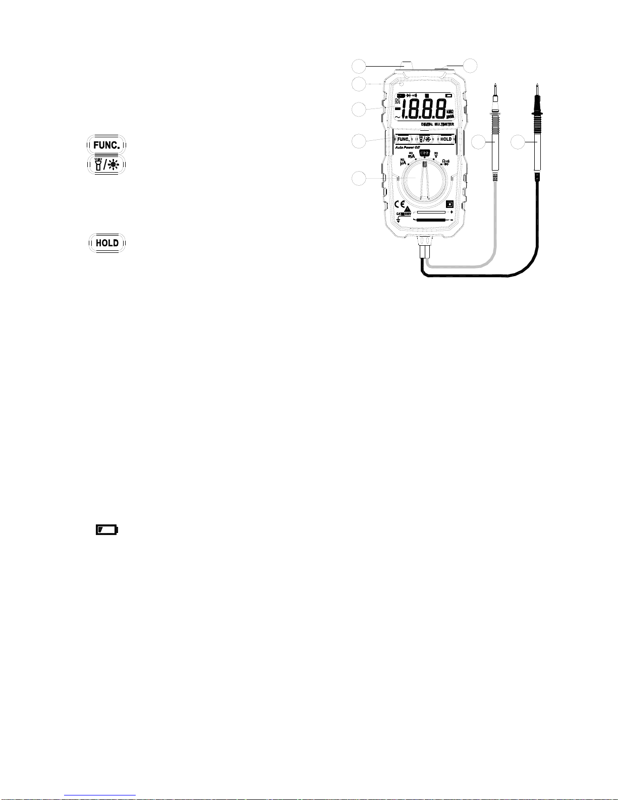
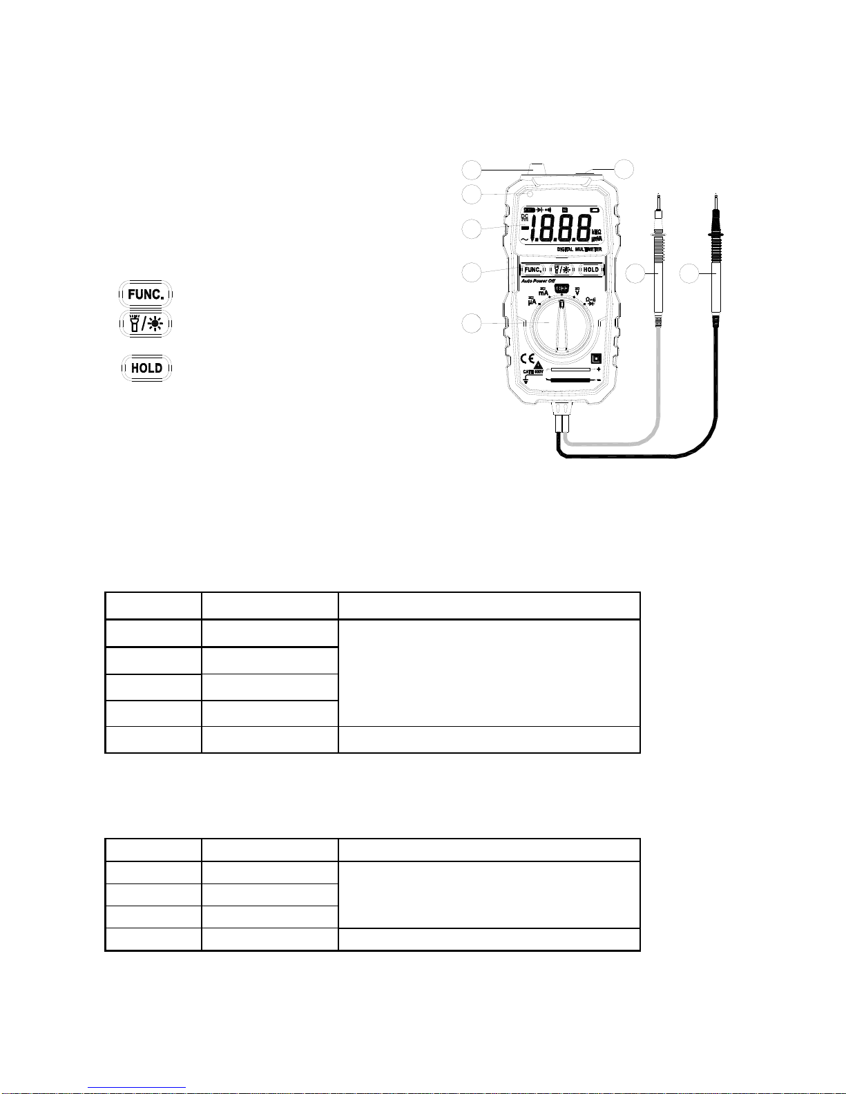
INTRODUCTION
1. Flashlight
2. Non-contact voltage detecting probe
3. Non-contact voltage indicator
4. Display
5. Function key
: Function selection button
: Turn on display backlight and flashlight,
press and hold it for 2 seconds, the
backlight will be turn off. The auto
power off function will automatically
turn off after approx. 15 seconds of no
operation.
: Data hold button
6. Rotary switch
7. Red probe of test lead
8. Black probe of test lead
General Specifications
Environment condition of use:
IEC/EN 61010-1 600V CAT III, pollution level 2
Altitude < 2000 m
Working environment temperature and humidity: 0~40℃
(do not consider when it’s <80% RH, <10℃)
Storage environment temperature and humidity: -10~60℃ (<70% RH, remove the battery)
Temperature coefficient: 0.1 accuracy /℃
Maximum voltage allowed between the measuring terminal and the ground: 600V DC or AC
RMS
Fuse protection: fuse FF250mA/600V
Sampling rate: about 3 times/second.
Display: 3 1/2 bit LCD
Over range indication: LCD display will show “OL”.
Low battery indication: when the battery voltage is lower than the normal working voltage,
“ ” will be displayed on the LCD display.
Input polarity indication: automatically display “”
Power requirement: 2x1.5V AAA batteries
Dimension: 125*60*26mm
Accuracy Specifications
The accuracy applies up to one year after the calibration.
Reference condition: environment temperature 18℃ to 28℃, relative humidity is no more than
80.
AC
1
2
3
4
5
6
7
8
Page 5
4
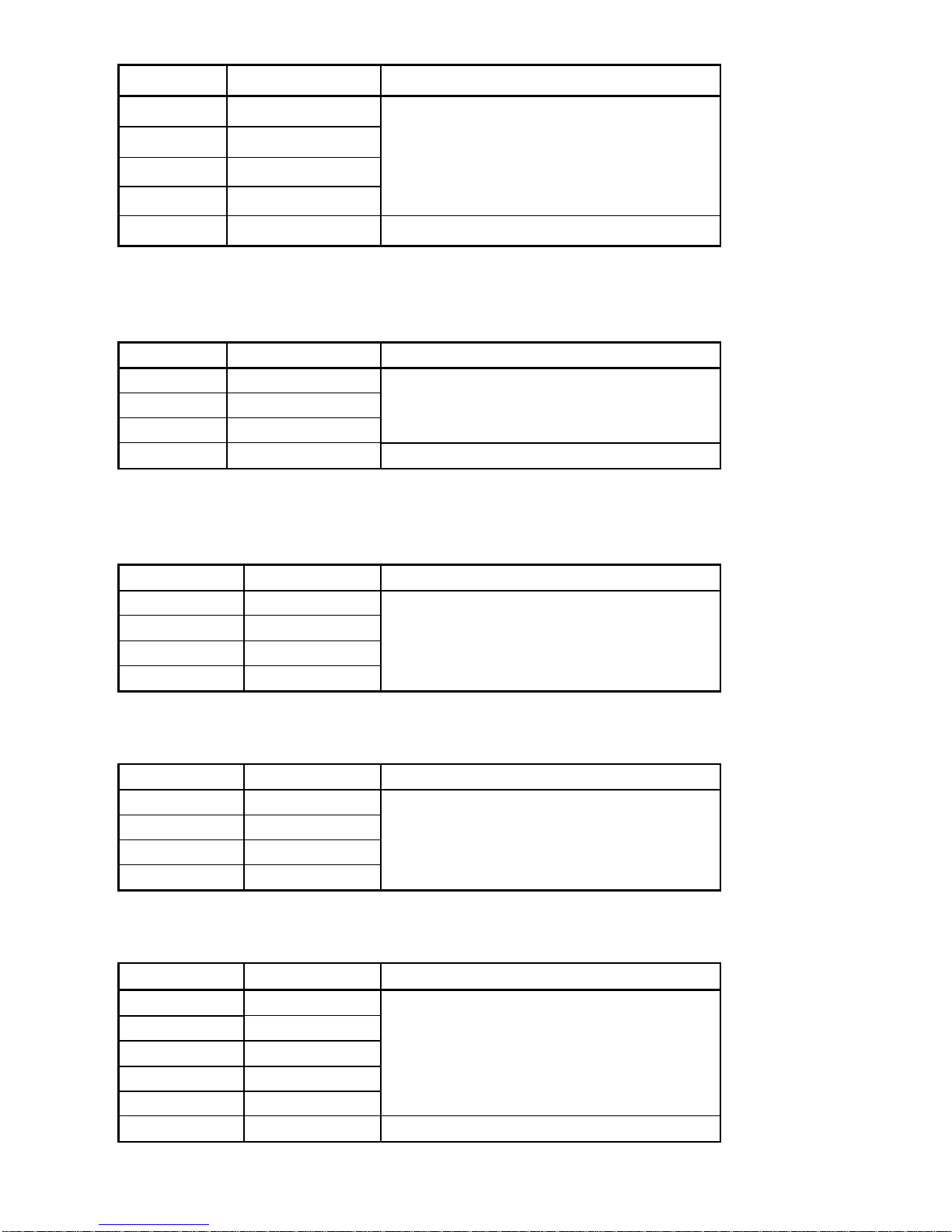
DC Voltage
Range
Resolution
Accuracy
200mV
0.1mV
± (0.5% readings+3)
2V
0.001V
20V
0.01V
200V
0.1V
600V
1V
±(0.8% reading +5)
Input impedance: 10MΩ
Maximum input voltage: 600V DC or AC RMS
AC Voltage
Range
Resolution
Accuracy
2V
0.001V
±(0.8 reading +3)
20V
0.01V
200V
0.1V
600V
1V
±(1.0% reading +5)
Input impedance: 10MΩ Maximum input voltage: 600V DC or AC RMS.
Frequency range: 40Hz~400Hz;
DC Current
Range
Resolution
Accuracy
200uA
0.1uA
±(1.8% reading +5)
2000uA
1uA
20mA
0.01mA
200mA
0.1mA
Input protection: FF250mA/600V fuse.
AC Current
Range
Resolution
Accuracy
200uA
0.1uA
±(2.0% reading +5)
2000uA
1uA
20mA
0.01mA
200mA
0.1mA
Input protection: FF250mA/600V fuse.
Resistance
Range
Resolution
Accuracy
200Ω
0.1 Ω
±(1.0% reading+3)
2kΩ
0.001 kΩ
20kΩ
0.01 kΩ
200kΩ
0.1 kΩ
2MΩ
0.001MΩ
20MΩ
0.01 MΩ
±(1.2% reading+15)
Input protection: Maximum 600V DC or AC RMS.
Page 6
5
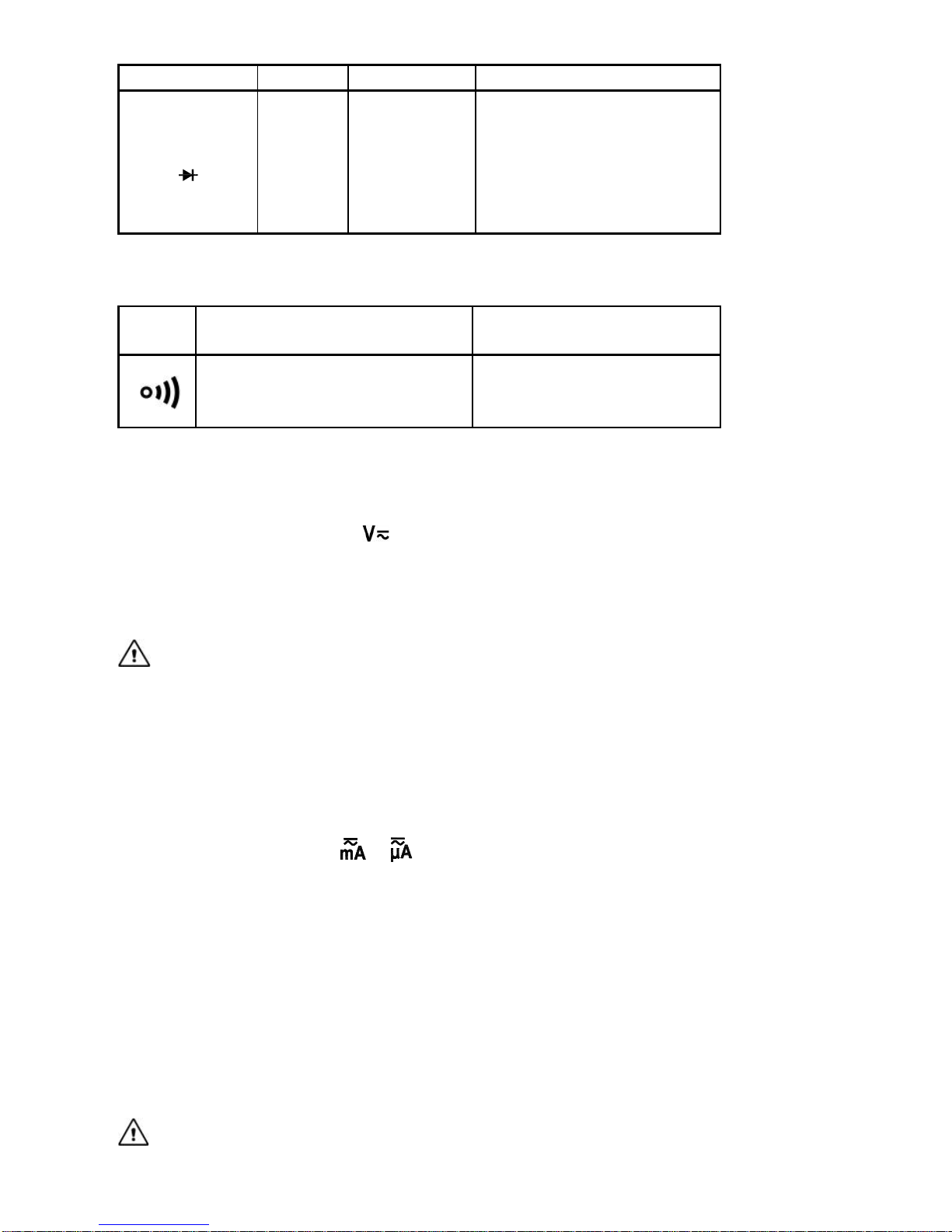
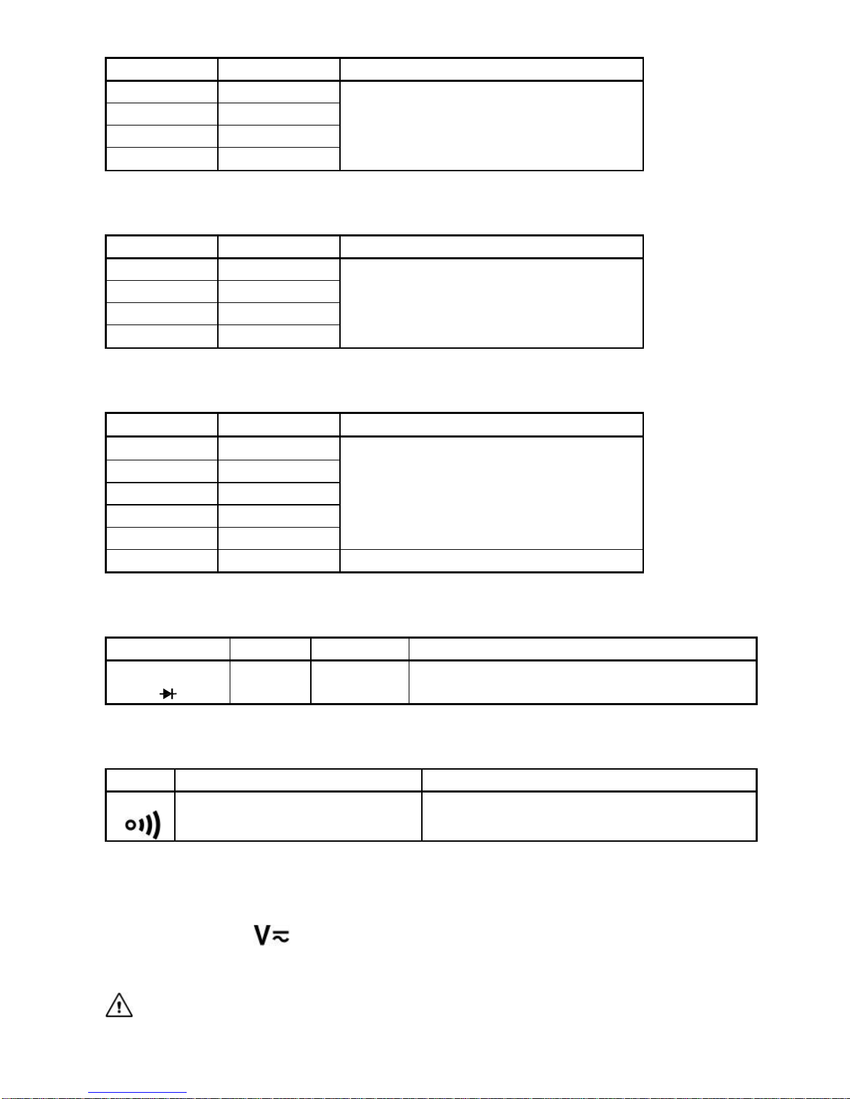
Diode
Function
Range
Resolution
Testing environment
Diode test
1 V
0.001V
Test current: about 1mA;
open circuit voltage: about
2.8V.
The display shows the
approximate value of diode
forward voltage drop.
Input protection: Maximum 600V DC or AC RMS.
Buzzer on/off
Funct
ion
Description
Testing environment
When the built-in buzzer
sounds, the measured
resistance is less than 50.
Test current: 1mA; open
circuit voltage: about 2.8V.
Input protection: Maximum 250V DC or AC RMS.
METHOD OF MEASUREMENT
AC and DC Voltage Measurement
1. Scroll the rotary switch to , press “FUNC.” button, select DC voltage or AC voltage
measurement.
2. Connect the probe in parallel to the circuit or power supply to be measured.
3. Read the measuring value from the display. When measuring DC voltage, the display also
shows the voltage polarity of the red probe test point.
Warning
Do not input voltage higher than 600V, it’s possible to display higher voltage, but there may
be risk of damaging the instrument.
When measuring high voltage, be careful to avoid electric shock.
After completing all the measuring operation, make sure to disconnect the probe from the
measured circuit.
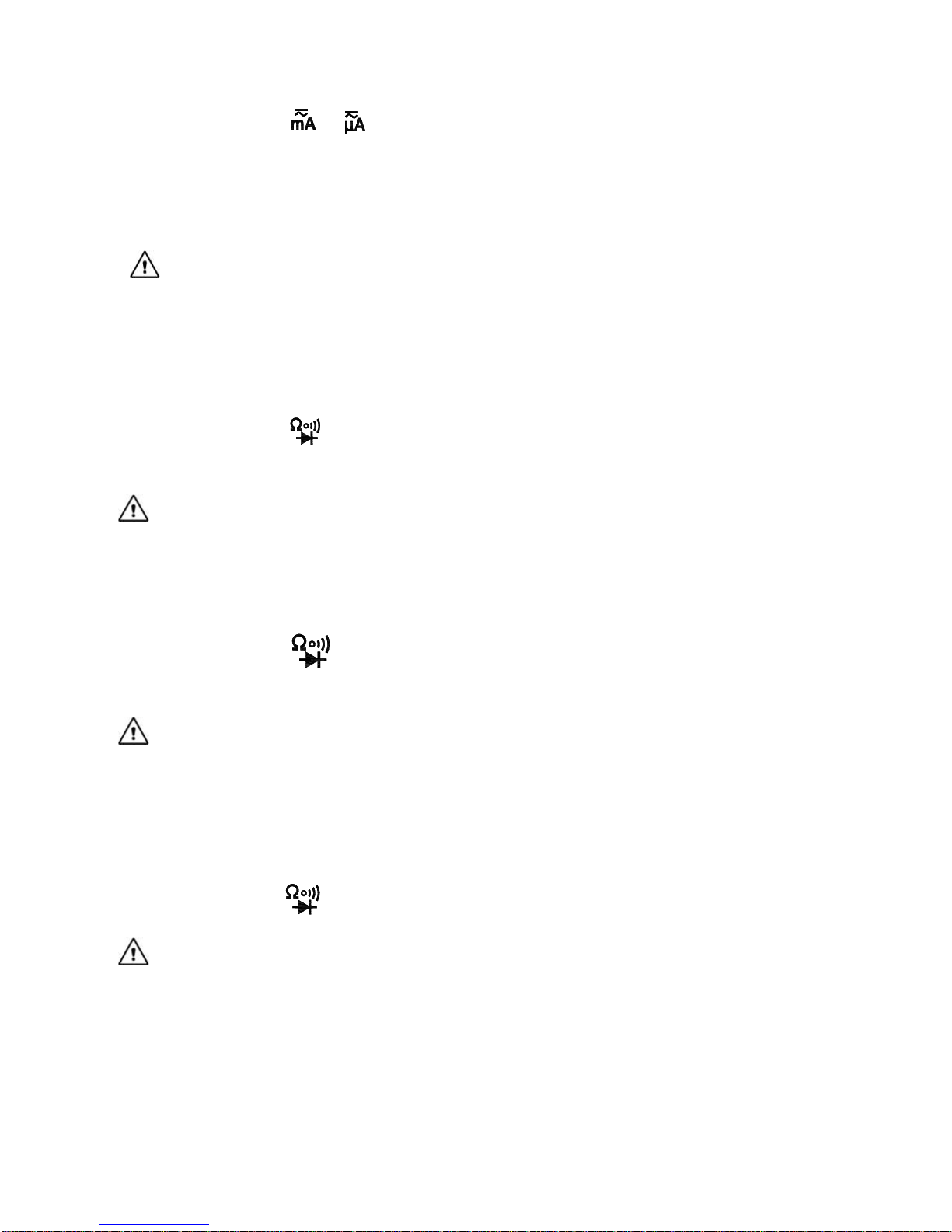
AC and DC Current Measurement
1. Turn the rotary switch to or , press “FUNC.” button, select DC current or AC current
measurement.
2. Shut off the power supply of the circuit under test. Discharge all the high voltage capacitors
on the circuit under test.
3. Disconnect the circuit to be measured. Connect the instrument to the circuit to be measured
in series.
4. Connect to the power of the circuit, and then read the measuring result from the display. If it
displays “OL”, it means the input exceeds the measuring range of the instrument. When
measuring the DC and AC, it will show the voltage polarity of red probe test point on the
display as well.
5. Shut off the power of the circuit under test. Remove the probe of the instrument and restore
the circuit.
Warning
To prevent possible electric shock, fire or personal injury, when measuring the current,
Page 7
6
please disconnect the power of the circuit under test in advance, and fully discharge all the
high voltage capacitors, then connect the instrument to the circuit in series.
Do not input above 200mA maximum measurement current value of the instrument,
otherwise it may burn the fuse in the instrument.
After completed all the measuring operation, please disconnect the probe from the circuit
under test.
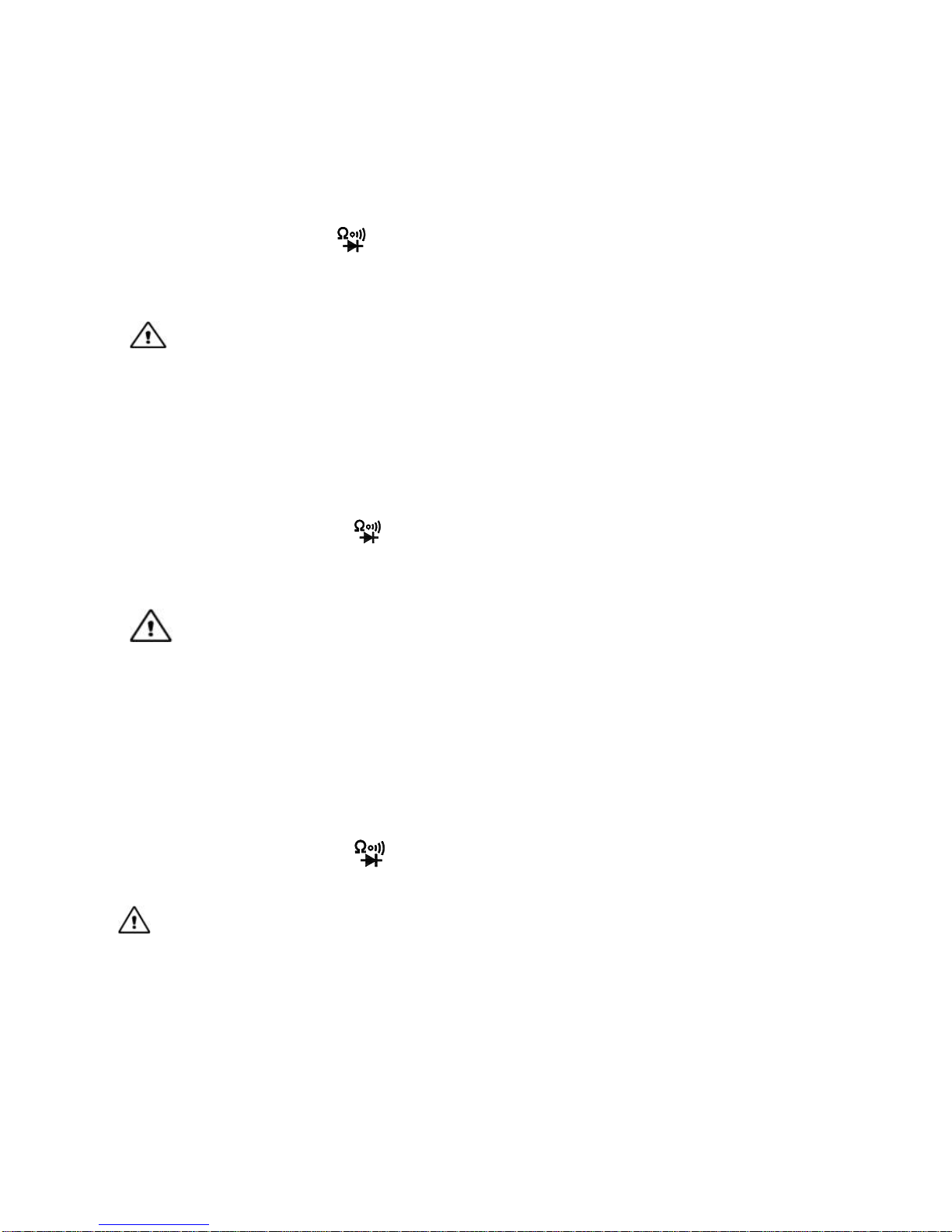
Resistance Measurement
1. Turn the rotary switch to , (if not resistance measurement function, please press
“FUNC.” button to switch to resistance measurement function)
2. Connect the probe to the circuit under test in parallel to measure the resistance.
3. Read the measuring results from the display.
Warning
To prevent possible electric shock, fire or personal injury, before measuring the resistance,
please disconnect the power supply of the circuit under test in advance, and fully discharge
all the high voltage capacitors.
After completed all the measurement operation, make sure to disconnect the probe from
the circuit under test.
Diode Test
1. Turn the rotary switch to , press “FUNC.” button to switch to the diode function
2. Connect the red probe to the anode of the diode to be measured, and the black probe to
the cathode of the diode to be measured, the reads on the display is the approximate value
of diode forward voltage drop. If connected backwards, it will display “OL”.
Warning
To prevent possible electric shock, fire or personal injury, before measuring the diode or
connectivity, please disconnect the power supply of the circuit to be measured in advance,
and fully discharge all the high voltage capacitors.
If the measured diode is open circuit or in reverse polarity, the instrument will display “OL”.
After completing all the measurement operations, make sure to disconnect the probe from
the circuit under test.
Connectivity Test
1. Turn the rotary switch to , press “FUNC.” button to switch to connectivity function
2. Connect the instrument to both ends of the circuit to be measured, when the resistance of
the measured circuit is less than 50Ω, the buzzer will sound.
Warning
To prevent possible electric shock, fire or personal injury, before measuring the diode or
connectivity, please disconnect the power supply of the circuit to be measured in advance,
and fully discharge all the high voltage capacitors.
After completing all the measurement operations, make sure to disconnect the probe from
the circuit under test.
Non-contact Voltage Detection
1. Turn the rotary switch of the instrument to any position except OFF.
2. Put the non-contact voltage detecting probe of the instrument close to the live wire of the
AC voltage (less than 5mm).
Page 8
7
3. The indicator of the non-contact voltage will light up, it shows that there’s AC voltage on
the live wire.
INSTRUMENT MAINTENANCE
This section provides the basic maintenance information, including description of replacing fuse
and batteries.
Warning
Do not try to repair the instrument unless you are experienced repair person and have
associated calibration, performance test and maintenance information.
To prevent possible electric shock, fire or personal injury:
When the cabinet is opened, do not use the instrument to do any measurement.
Remove the input signal before cleaning the instrument.
Specified replacement parts shall be used. Please ask the qualified technicians to repair
the instrument.
General Maintenance
Use a damp cloth and a small amount of detergent to clean the housing of the instrument.
Please do not use abrasive or chemical solvents.
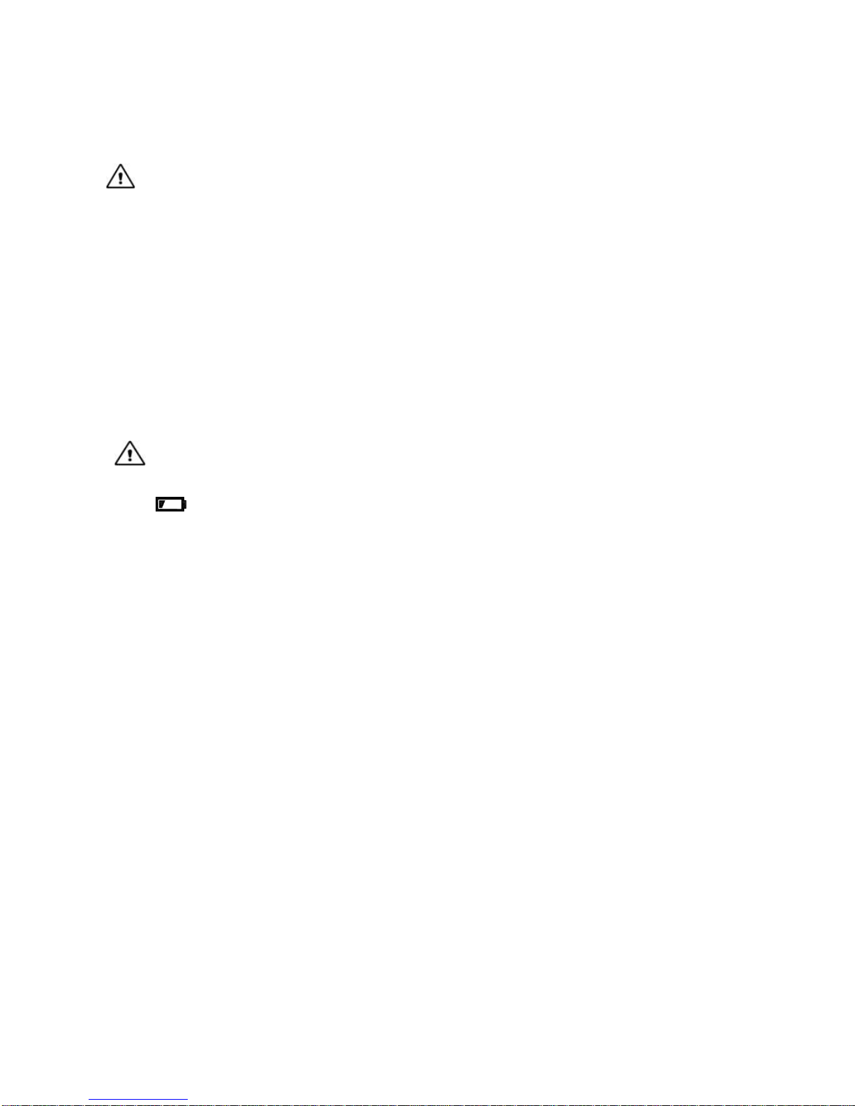
Replace Fuse and Battery
Warning
To prevent electric shock or personal injury caused by error reading, when it displays
“ ” on the screen, the batteries should be replaced.
To ensure safety operation and maintenance, when the instrument will not be used for a
long period, please remove the batteries to avoid any damage caused by battery leakage.
Use the fuse with specified amperage, fuse ratings, voltage ring and fuse speed.
To avoid electric shock or personal injury, before opening the back cover to replace
batteries, the instrument should be shut down and checked to ensure that the probe has
already been disconnected from the measuring circuit.
Please follow the steps as below to replace the battery:
1. Power off the instrument.
2. Disconnect the probe from the circuit under test.
3. Unscrew and open the cover of battery compartment on the back of this instrument.
4. Remove the exhausted batteries, replace with new batteries.
5. Close and screw the cover.
Please follow the steps as below to replace the fuse:
1. Turn off the power of the instrument.
2. Disconnect the probe from the circuit under test.
3. Unscrew and open the cover on the back of this instrument.
4. Remove the damaged fuse, replace with new fuse.
5. Close and screw the cover.
Page 9

8
MT-1508 袖珍型電表使用說明書
聲明
根據國際版權法,未經允許和書面同意,不得以任何形式(包括存儲和檢索或翻譯為其他國家或
地區語言)複製本說明書的任何內容。本說明書在將來的版本中如有更改,恕不另行通知。
小心
“小心”標誌表示會對儀錶或設備造成損壞的狀況和操作。它要求在執行此操作時必須小心,如果
不正確執行此操作或不遵循此操作步驟,則可能導致儀錶或設備損壞。在不滿足這些條件或沒有
完全理解的情況下,請勿繼續執行小心標誌所指示的任何操作。
警告
“警告”標誌表示會對用戶造成危險的狀況和操作。它要求在執行此操作時必須注意,如果不正確
執此行操作或不遵守此操作步驟,則可能導致人身傷害或傷亡。在不滿足這些條件或沒有完全理
解的情況下,請勿繼續執行警告標誌所指示的任何操作。
使用儀錶前,請仔細閱讀說明書並注意有關安全警告資訊。
概述
本儀錶是一款可隨身攜帶的數字萬用表。它性能穩定,精度高,功耗低,結構新穎,安全可靠,是廣
大用戶的理想測量儀錶。
儀錶可以測量直流電壓、交流電壓、直流電流、交流電流、電阻、二極體及連通性;具有非接觸
電壓探測功能,及時提醒用戶注意操作安全,讓用戶使用更安全、放心。
本說明書包括有關的安全資訊和警告提示等,使用儀錶前請仔細閱讀有關內容,並嚴格遵守所有
的警告和注意事項。
安全須知
本儀錶嚴格遵循安全標準 IEC61010 進行設計和生產,符合雙重絕緣、過電壓標準 600V CAT III
和污染等級 2 的安全標準。
請遵循本說明書使用儀錶,否則儀錶所提供的保護功能可能會降低或無效。
安全操作規範
警告
為了避免可能的觸電或人身傷害,請切實遵守以下的規範:
使用儀錶前,請先閱讀“安全須知”。並嚴格按照規定使用儀錶,否則儀錶所提供的保護能力
可能會降低或無效。
使用儀錶前先檢查外殼。檢查是否存在裂紋或塑膠件缺損。請仔細檢查輸入端子附近的絕緣
體。
若儀錶工作不正常或損壞,請勿使用。
禁止觸摸電壓超過 30V 真有效值交流電、42 V 交流電峰值或 60V 直流電的帶電帶體。
應按照指定的測量類別、電壓或電流額定值使用儀錶。
當顯示電池電量不足指示時請及時更換電池,以防測量錯誤。
請遵守當地和國家的安全規範。穿戴個人防護用品(經認可的橡膠手套、面具和阻燃衣物
等),以防危險帶電導體外露時遭受電擊和電弧而受傷。
輸入端子間或每個端子與接地點之間施加的電壓不能超過儀錶規定額定值。
測量一個已知電壓,以確定儀錶操作是否正常。
測量時,必須使用正確的輸入端子、功能檔位和量程檔位。
請勿在爆炸性氣體、蒸汽周圍或在潮濕環境中使用儀錶。
請勿使用已損壞的表棒。檢查表棒的絕緣層是否損壞,是否有外露金屬或有磨損跡象。檢查
Page 10
9
表棒的通斷性。
測量時,請先連接零線或地線,再連接火線;斷開時,請先切斷火線,再斷開零線和地線。
測量時,請將手指握在表棒護指裝置的後面。
打開儀錶後蓋之前,請先斷開表棒與被測量物件。
請勿在超出儀錶、表棒或附件中額定值最低的單個元件的測量類別 (CAT) 額定值的環境中
使用儀錶。
電氣符號
高壓警告
AC(交流電)
DC(直流電)
交流電或直流電
警告,重要安全標誌
接地
保險絲
設備由雙重絕緣或加強絕緣保護
電池電量不足
符合歐洲共同體(European Union)標準
說明不得將此電氣/電子產品丟棄在家庭垃圾中。
CAT II
II 類測量適用於測試和測量與低電壓電源裝置的用電點
(插座和相似點)直接連接的電路
CAT III
III 類測量適用於測試和測量與建築物低電壓電源裝置配電
部分連接的電路
CAT IV
IV 類測量適用於測試和測量與建築物低電壓電源裝置電
源連接的電路
通用技術指標
使用環境條件:
IEC/EN 61010-1 600V CAT III,污染等級 2
海拔高度 < 2000 m
工作環境溫濕度:0~40℃(<80% RH,<10℃時不考慮)
儲存環境溫濕度:-10~60℃(<70% RH, 取掉電池)
溫度係數:0.1準確度/℃
測量端和地之間允許的最大電壓:600V 直流或交流有效值
保險管保護:保險管 FF 250mA/600V
採樣速率:約 3 次/秒。
顯示:3 1/2 位液晶顯示幕
超量程指示:液晶顯示器將顯示“OL”。
電池低壓指示:當電池電壓低於正常工作電壓時,“ ”將顯示在液晶螢幕上。
Page 11
10
輸入極性指示:自動顯示“”號
電源: 2x1.5V AAA 電池
外形尺寸:125*60*26mm
儀錶說明
1. 照明燈
2. 非接觸電壓感應區
3. 非接觸電壓指示燈
4. 顯示幕
5. 按鍵說明:
:功能選擇按鍵
:
背光及照明燈開關鍵,按下並保持 2 秒,背
光點亮,約 15 秒後將自動熄滅或再按下並
保持 2 秒手動熄滅。
:資料保持鍵
6. 檔位旋鈕
7. 紅色表棒
8. 黑色表棒
準確度指標
準確度在校準後一年內適用。
基準條件:環境溫度 18℃至 28℃、相對濕度不大於 80。
直流電壓
量程
解析度
準確度
200mV
0.1mV
±(0.5% 讀數 +3 字)
2V
0.001V
20V
0.01V
200V
0.1V
600V
1V
±(0.8% 讀數 +5 字)
輸入阻抗:10MΩ
最大輸入電壓:600V DC 或 AC 有效值。
交流電壓
量程
解析度
準確度
2V
0.001V
±(0.8 讀數 +3 字)
20V
0.01V
200V
0.1V
600V
1V
±(1.0% 讀數 +5 字)
輸入阻抗:10MΩ 最大輸入電壓:600V DC 或 AC 有效值。
頻率範圍:40Hz~400Hz ;
AC
1
2
3
4
5
6
7
8
Page 12
11
直流電流
量程
解析度
準確度
200uA
0.1uA
±(1.8% 讀數 +5 字)
2000uA
1uA
20mA
0.01mA
200mA
0.1mA
輸入保護: FF 250mA/600V 保險管。
交流電流
量程
解析度
準確度
200uA
0.1uA
±(2.0% 讀數 +5 字)
2000uA
1uA
20mA
0.01mA
200mA
0.1mA
輸入保護: FF250mA/600V 保險管。
電阻
量程
解析度
準確度
200Ω
0.1 Ω
±(1.0% 讀數 +3 字)
2kΩ
0.001 kΩ
20kΩ
0.01 kΩ
200kΩ
0.1 kΩ
2MΩ
0.001MΩ
20MΩ
0.01 MΩ
±(1.2% 讀數 +15 字)
輸入保護:最大 600V DC 或 AC 有效值。
二極體.
功能
量程
解析度
測試環境
二極體測試
1 V
0.001V
測試電流:約 1mA;開路電壓:約 2.8V。
顯示器顯示二極體正向壓降的近似值。
輸入保護:最大 600V DC 或 AC 有效值。
蜂鳴通斷
功能
說明
測試環境
當內置蜂鳴器發聲時,被測電阻
不大於約 50。
測試電流:約 1mA;開路電壓:約 2.8V。
輸入保護:最大 600V DC 或 AC 有效值。
測量方法
交直流電壓測量
1. 將旋鈕開關旋到 檔位,然後按”FUNC.”鍵,選擇直流電壓或交流電壓測量。
2. 將表棒並聯到待測電路或電源上,測量電壓。
3. 從顯示幕讀取測量結果。測量直流電壓時,顯示幕同時顯示紅色表棒測試點的電壓極性。
警告
不要輸入高於 600V 的電壓,顯示更高電壓值是可能的,但可能會有損壞儀錶的危險。
Page 13
12
測量高電壓時,要格外小心,以避免觸電。
在完成所有的測量操作後,要斷開表棒與被測電路的連接。
交直流電流測量
1. 將旋鈕開關旋到 或 檔位,然後按”FUNC.”鍵,選擇直流電流或交流電流測量。
2. 切斷被測電路的電源。將被測電路上的全部高壓電容放電。
3. 斷開待測的電路。將儀錶串聯到待測量電路。
4. 接上電路的電源,然後從顯示幕讀出測量結果。如果顯示幕只顯示“OL”,這表示輸入超過儀
錶測量範圍。測量直流電流時顯示幕同時顯示紅色表棒測試點的電壓極性。
5. 切斷被測電路的電源。移走儀錶的表棒並把電路恢復原狀。
警告
為了防止可能發生的電擊、火災或人身傷害,測量電流時,先斷開被測電路電源,並將所有
高壓電容充分放電,然後再將儀錶串聯到電路中。
不要輸入高於儀錶最大測量電流值 200mA,否則有可能燒斷儀錶內保險管。
在完成所有的測量操作後,要斷開表棒與被測電路的連接。
電阻測量
1. 將旋鈕開關轉到 檔位,(如果不是電阻測量功能請按“FUNC.”鍵切換到電阻測量功能)
2. 將表棒並聯接上待測電路,測量電阻。
3. 從顯示幕讀取測量結果。
警告
為了防止可能發生的電擊、火災或人身傷害,測量電阻之前請先斷開待測電路的電源,並為
所有高壓電容器充分放電。
在完成所有的測量操作後,要斷開表棒與被測電路的連接。
二極體測試
1. 將旋鈕開關旋到 檔位,按“FUNC.”鍵切換到二極體功能
2. 將紅表棒連接到待測二極體的正極,黑表棒連接到待測二極體的負極,則顯示幕上的讀數為
二極體正向壓降的近似值。反接將顯示“OL”
警告
為了防止可能發生的電擊、火災或人身傷害,測量二極體或連通性之前請先斷開待測量電路
電源並為所有高壓電容器充分放電。
如果被測二極體開路或極性接反,儀錶將顯示“OL”。
在完成所有的測量操作後,要斷開表棒與被測電路的連接。
連通性測試
1. 將旋鈕開關旋到 檔位,按“FUNC.”鍵切換到連通性功能
2. 將表棒並聯到被測量電路兩端,當被測量電路阻值小 50Ω 時,蜂鳴器將發出聲響。
警告
為了防止可能發生的電擊、火災或人身傷害,測量二極體或連通性之前請先斷開待測量電路
電源並為所有高壓電容器充分放電。
在完成所有的測量操作後,要斷開表棒與被測電路的連接。
非接觸電壓檢測
1. 將儀錶旋鈕旋到任何檔位, 不可在 OFF 檔位。
2. 將儀錶上方非接觸電壓感應區靠近(小於 5mm)交流電壓的火線。
3. 儀錶非接觸電壓指示燈將點亮,表示火線上有交流電壓。
Page 14

13
儀錶維護
本節提供基本的維護資料,包括更換保險管和更換電池的說明。除非您是有經驗的維修人員且有
相關的校準、性能測試以及維修資料,否則不要嘗試去維修本儀錶
警告
為了防止可能發生的觸電、火災或人身傷害:
在機殼打開時,請勿使用儀錶進行任測量操作。
清潔儀錶前先移除輸入信號。
應使用指定的替換零件。請經過認可的技術人員維修儀錶。
一般維護
用濕布和少量洗滌劑清潔儀錶外殼, 請勿用研磨劑或化學溶劑。
更換保險管及電池
警告
為避免錯誤的讀數而導致電擊或人身傷害,儀錶顯示幕出現“ ”符號時,應及時更換電池。
為了確保安全操作和維護該產品,儀錶長期不用時,請取出電池,以防電池漏電對產品造成
損壞。
只能使用指定的安培數,熔斷額定值,電壓額定值及熔斷速度的保險管
為避免電擊或人身傷害,在打開後蓋更換電池之前,應關機並檢查確保表棒已從測量電路斷
開。
請按照以下步驟更換電池:
1. 關閉儀錶電源, 並將表棒與被測量電路斷開。
2. 取下固定外殼的螺釘,然後拆開電池蓋。
3. 取下舊電池,換上新的電池。
4. 裝上後蓋,上緊螺釘, 裝上膠套。
請按照以下步驟更換保險管:
1. 關閉儀錶電源, 並將表棒與被測量電路斷開。
2. 分離外殼與膠套。
3. 取下固定外殼的螺釘,然後拆開外殼蓋。
4. 取下損壞的保險管,換上新的保險管。
5. 裝上外殼蓋,上緊螺釘, 裝上膠套。
Page 15
14
中國地區產品保固卡
購買日期
店章
公司名稱
聯絡電話
電子郵箱
聯絡地址
產品型號
□ MT-1508
※ 在正常使用情況下,自原購買日起 12 個月免費維修保證(不含耗材、
消耗品)。
※ 產品保固卡需蓋上店章、日期章,其保固效力始生效。
※ 本卡請妥善保存,如需維修服務時,請出示本卡以為證明。
※ 保固期滿後,屬調整、保養或是維修性質之服務,則酌收檢修工時
費用。若有零件需更換,則零件費另計。
產品保固說明
保固期限內,如有下列情況者,維修中心則得酌收材料成本或修理費
(由本公司維修人員判定):
• 對產品表面的損傷,包括外殼裂縫或刮痕
• 因誤用、疏忽、不當安裝或測試,未經授權打開產品修理,修改
產品或者任何其他超出預期使用範圍的原因所造成的損害
• 因事故、火災、電力變化、其他危害,或自然災難所造成的損害。
非服務保證內容:
• 機件本體外之消耗品:如電池...等消耗品
• 機件本體之外之附配件:如耳機麥克風,電源供應器,記憶卡,
CD 等附配件。
三.超過保證期限之檢修或服務,雖未更換零件,將依公司保固維修政
策酌收服務費。
服務電話: 0755 83692415 / 83692986 /83246594 / 83247554
服務傳真: 0755 83692143
Page 16

15
©2015 Prokit’s Industries Co., Ltd. All rights reserved. 2015001
 Loading...