

Page 1
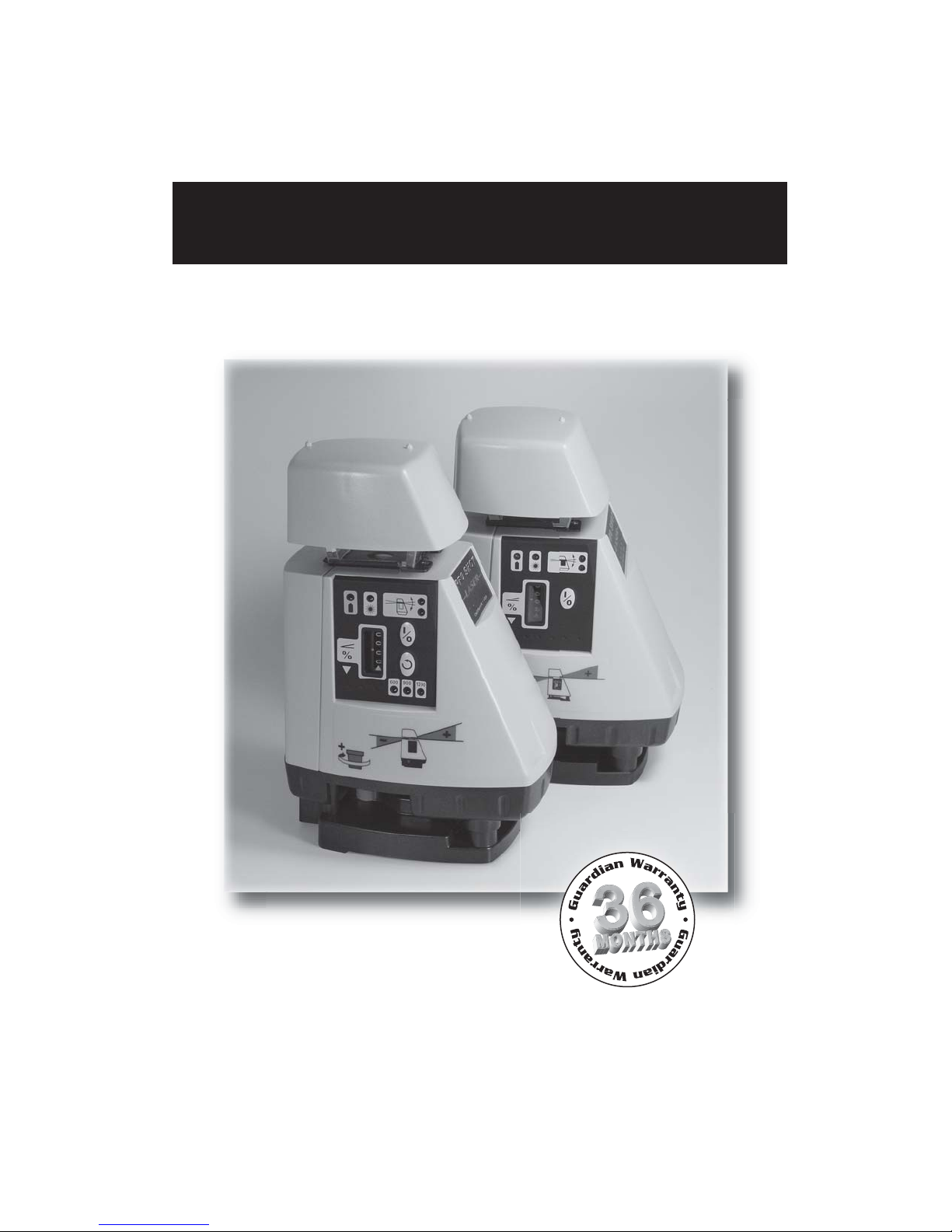
PRO SHOT
PRO SHOT
TM
Slope Lasers
AS2 \ AS2
MAGNUM
TM
Slope Lasers
AS2 \ AS2
Operations Guide
MAGNUM
Page 2

Introduction
Thank you for purchasing a Pro ShotTM AS2 or AS2 MAGNUM laser system.
You now have superior laser accuracy and productivity available for all your
projects.
Both Pro ShotTM AS2 laser models are rugged, reliable, high quality products,
backed by the industry leading Guardian 36 month warranty. Warranty
details are printed in the back of this manual.
Please take the time to thoroughly read this manual. It contains vital
information on how to safely get the most from your investment in high
performance laser technology.
Contents
Battery Installation ............................................................... 1
Controls and Displays .......................................................... 2
Safety ........
Initial Setup Guidelines ........................................................ 6
Level Setup .......................................................................... 7
Slope setup .......................................................................... 8
Compound Slope Setup ..................................................... 10
Checking & Adjusting Calibration ...................................... 12
R7 • AS2 System Receiver ................................................ 14
R8 • AS2 MAGNUM System Receiver .................................. 15
Maintenance and Troubleshooting ..................................... 16
Guardian Warranty and Specifications ............................. 17
.........
................................................................... 4
Page 3
Getting Started
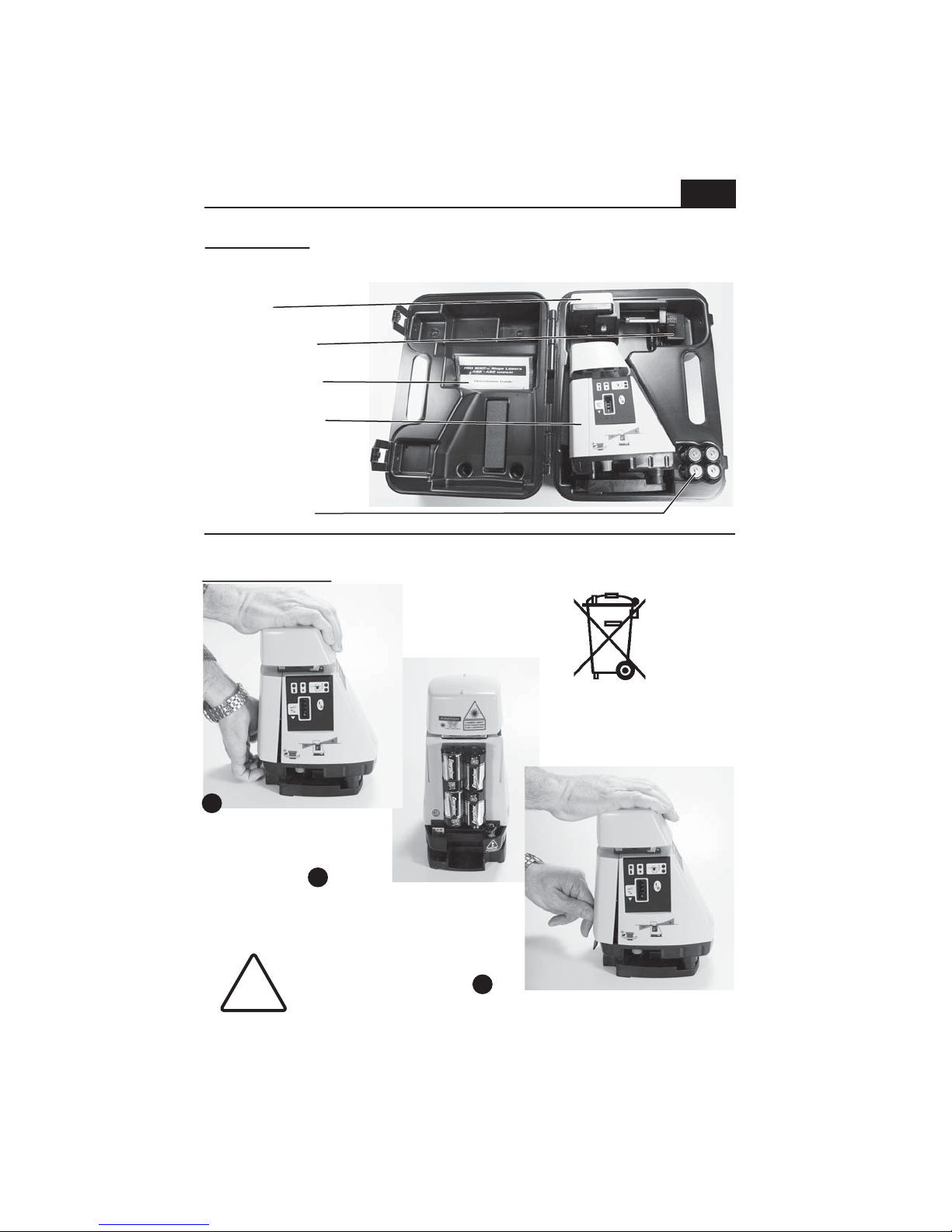
Pull on tab at base
of door to remove
Hook battery door under
metal plate below lighthouse
and push at base of door to latch
I nstall batteries according
to the instructions molded on
the battery holder
Case contents (will vary - may be ordered with different accessories)
Receiver
Battery charger
Manual package
Laser transmitter
C-cell batteries
1
Battery installation
1 Pull on tab at base
1 Pull on tab at base
of door to remove
of door to remove
2 I nstall batteries according
2 Install batteries according
to the instructions molded on
to the instructions molded on
the battery holder
the battery holder
!
CHARGE ONLY
RECHARGEABLE
BATTERIES
Always follow recycling
directives for electronic waste
3 Hook battery door under
3 Hook battery door under
metal plate below lighthouse
metal plate below lighthouse
and push at base of door to latch
and push at base of door to latch
Page 4
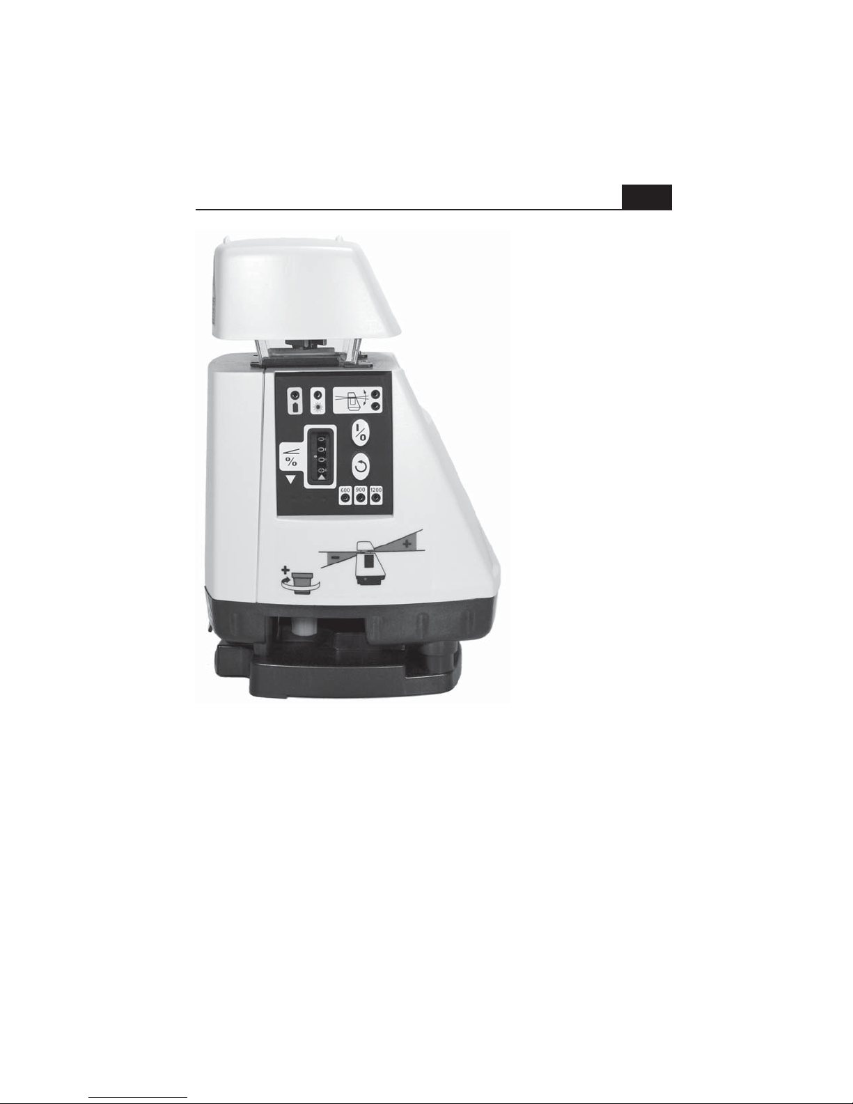
Controls and Displays
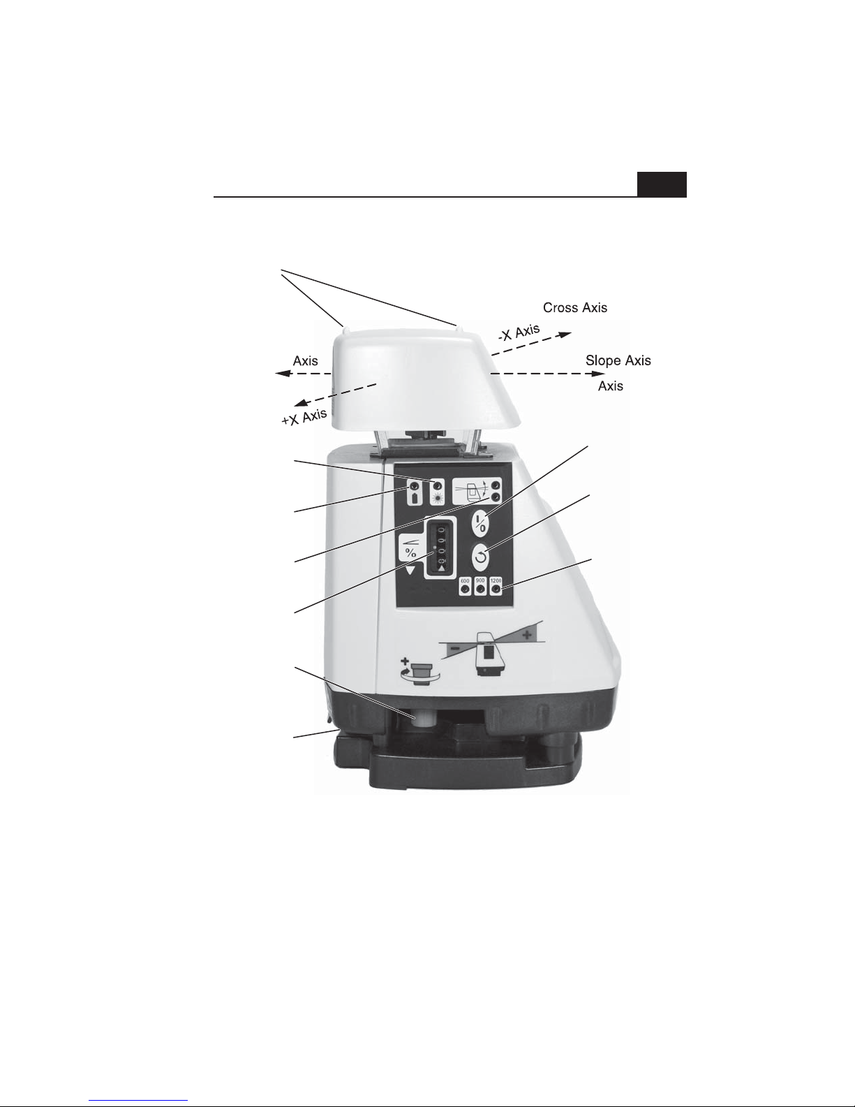
Slope
Alignment
Sights
-Y
Laser Power
Indicator
Low Battery
Indicator
+Y
Power
Switch
Rotation Speed
Selector
(
MAGNUM
2
)
Leveling
Indicators
Slope
Display
Slope
Adjustment
Knob
Charging
Jack
Note: Controls and displays are the same for both models
except that the AS2 MAGNUM has a rotation speed selection
button and speed indicator LEDs.
Rotation Speed
Indicators
(
MAGNUM
)
Page 5

Controls And Displays
3
• Slope alignment sights
These sights are used to align the slope axis of the laser for excavating and
grading when there is a slope required.
• Laser Power indicator
The green L.E.D. indicates the laser beam is on.
• Low battery indicator
The yellow L.E.D. indicates the batteries need to be replaced or charged.
• Leveling indicators / H.I. alert
A green L.E.D. in the upper leveling indicator control panel window turns on
when the leveling system is active. A constant light indicates the laser is
leveling. A flashing light indicates the laser is nearly level. When the laser is
fully level, the rotating mirror begins to spin, the green power indicator L.E.D.
comes on and the leveling L.E.D. turns off. If the laser cannot level, a red
L.E.D. in the lower leveling indicator control panel window will flash. This
indicates the tripod or surface the laser is on must be more level or closer to
the slope that is dialed in.
When the laser finishes leveling and has been running for about five
seconds, a feature called H.I. alert activates. When the laser enters this
mode, the upper leveling indicator green L.E.D. will flash slowly five times.
With H.I. alert active, if the laser is moved or bumped, or the grade knob is
moved, the laser beam will shut-off, the rotor will stop spinning and the red
and green leveling L.E.D.s will flash alternately. Any grade adjustments
should be made before H.I. alert activates. To clear the H.I. alert, simply turn
the laser off, then on again. You must recheck your setup before continuing
your work to avoid errors.
• Slope display
The counter displays the amount of slope set into the plane of laser light.
The display has a resolution of .01% and can be set from 0 to 25%.
• Slope adjustment knob (see H.I. alert above)
The slope adjustment knob is used to set slope into the laser, or to set the
laser to level (00.00 slope).
• Power switch
The power switch turns the laser on or off.
• Rotation speed selector (MAGNUM only)
The rotation speed switch changes the rotation speed between 600, 900 and
1200rpm. The speed will stay at the last setting when the laser is shut down.
• Rotation speed indicators (MAGNUM only)
One of these indiactors will be on whenever the laser is powered-up to
indicate the selected rotation speed.
Page 6
Safety
CAUT ION
LASER LIGHT
4
Precautions to follow when using any laser.
• Don't stare into the laser beam or view it directly with optical instruments.
• Don't disassemble the laser or attempt to service it.
• Don't use the laser until you have read the instruction manual and you are
familiar with how to operate the laser properly.
U.S. OSHA requirements for operating visible lasers.
• Only qualified, trained employees may install, adjust and operate the laser.
• Laser operators must carry proof of qualification.
• The area of a job site where a laser is being used must be posted with a
laser warning placard.
• The laser should be set up above or below eye level and never intentionally
aimed at anyone.
• Turn the laser off when it is not being used, such as during lunch hour, at
the end of the day, or during other long breaks in the work.
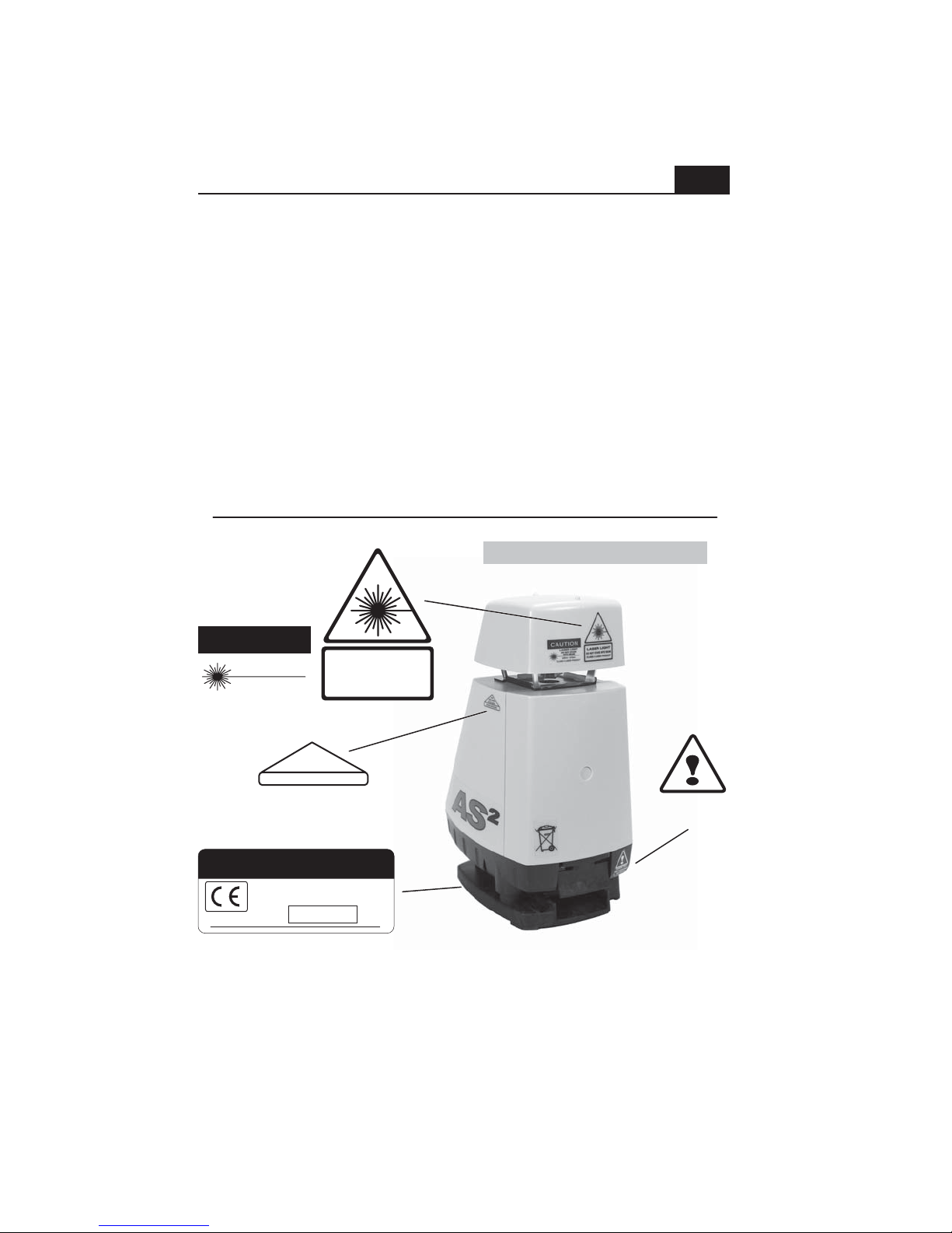
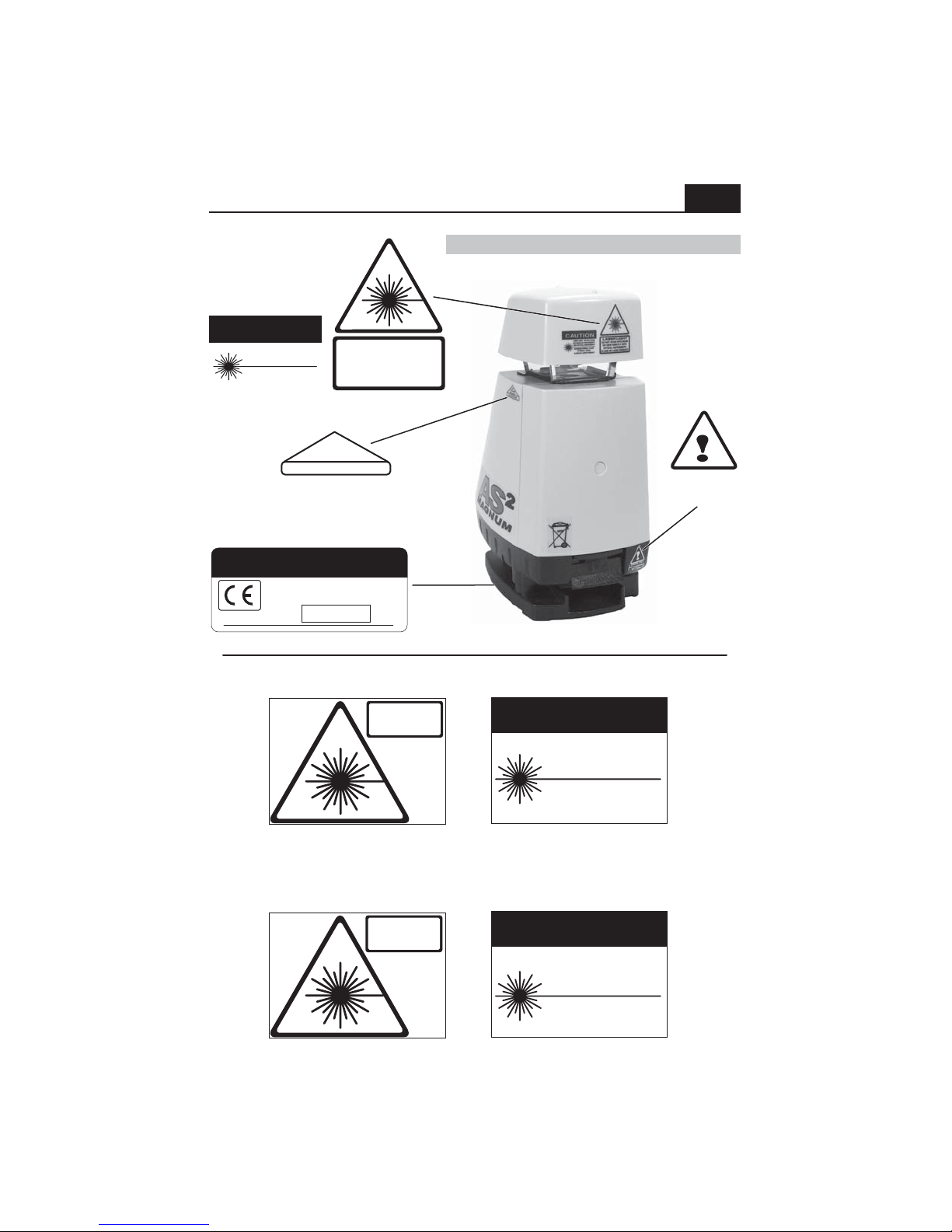
Safety label locations • AS2
CDRH / IEC
warnings
CAUTION
LASER LIGHT
DO NOT STARE
INTO BEAM
635nm - 670nm
CLASS II LASER PRODUCT
AVOID EXPOSURE
Aperture warning
LASER LIGHT
DO NOT STARE INTO BEAM
CLASS 2 LASER PRODUCT
Laser
Light is emitted
from this aperture
CHARGE ONLY
RECHARGEABLE
BATTERIES
Serial / CDRH / EC compliance
Manufactured by: Laser Reference, Inc.
151 Martinvale Lane • San Jose, CA 95119
This product complies with FDA
standards 21 CFR subchapter J
Serial No.
X 000000
Note: The L1-AS is a CDRH class II laser and an IEC 60825 class 2 laser.
The L1-AS
M MAGNUM is a CDRH class IIIa laser and an IEC 60825 class 3R
laser. Both models conform to applicable EC directives regarding RFI and
EMI and to FDA performance standards 21 CFR subchapter J.
Page 7
Safety
LASER LIGHT
CAUTION
LASER LIGHT
CAUTION
CAUT ION
LASER LIGHT
CDRH / IEC
warnings
CAUTION
LASER LIGHT - DO NOT STARE
INTO BEAM OR VIEW DIRECTLY
WITH OPTICAL INSTRUMENTS
MAXIMUM POWER < 2.5mW
AT 635nm - 670nm
CLASS IIIa LASER PRODUCT
Aperture warning
Serial / CDRH / EC compliance
Manufactured by: Laser Reference, Inc.
151 Martinvale Lane • San Jose, CA 95119
This product complies with FDA
standards 21 CFR subchapter J
Serial No.
X 000000
LASER LIGHT
DO NOT STARE INTO BEAM
OR VIEW DIRECTLY WITH
OPTICAL INSTRUMENTS
CLASS 3R LASER PRODUCT
Laser
Light is emitted
from this aperture
AVOID EXPOSURE
Safety label locations • AS2 MAGNUM
CHARGE ONLY
RECHARGEABLE
BATTERIES
5
L1-ASM MAGNUM (IEC)
LASER LIGHT
DO NOT STARE INTO BEAM
OR VIEW DIRECTLY WITH
OPTICAL INSTRUMENTS
CLASS 3R LASER PRODUCT
L1-ASM MAGNUM (CDRH)
CAUTION
P/N 010-9023
LASER LIGHT - DO NOT STARE
INTO BEAM OR VIEW DIRECTLY
WITH OPTICAL INSTRUMENTS
MAXIMUM POWER < 2.5mw
AT 635nm
CLASS IIIa LASER PRODUCT
A warning placard is included with each laser and can be attached to the outside
of the carrying case. The case can then be placed in a visible location near where
the laser is being used in order to meet jobsite posting requirements.
L1-AS (IEC)
LASER LIGHT
DO NOT STARE INTO BEAM
CLASS 2 LASER PRODUCT
L1-AS (CDRH)
CAUTION
LASER LIGHT
DO NOT STARE
INTO BEAM
635nm - 670nm
CLASS II LASER PRODUCT
Page 8

Initial Setup Guidelines
6
Calibration should be checked from time to time.
Although both AS2 models are calibrated at the factory and are
exceptionally rugged lasers, it is well worth the effort to check calibration
before you first use your laser (after shipping) and then from time to time
to ensure that you are doing the highest quality work possible. Always
check calibration if the laser has been handled roughly.
Check your setup.
Although not required, it is good jobsite practice when using any laser or
optical instrument to check your setup from time to time. Use
engineered benchmarks on the jobsite to assure that your setup is
correct and matches the design of the job. Particularily on very large
sites, or where accuracy is critical, taking a few minutes to verify the
elevation marks you have been given to work from makes sense.
Realize that even engineered benchmarks may not be perfect and
enough verification must be done to be confident you are properly set up.
If there are not suitable benchmarks on the site, you can set your own by
driving stakes and recording their elevations, or by marking the laser
beam height on stable objects such as telephone poles, concrete walls,
etc. The benchmarks should be 90
0
apart for greatest accuracy. Having
benchmarks to check is of great value for jobs where setups need to
match day after day. If you will only be using the setup for a brief time,
this may not be needed.
Work as close to the laser as possible.
You can work up to 1000 feet (305M) from the AS2 with the R7 receiver
and 1650 feet (500M) from the AS2 MAGNUM using the R8 receiver or
most brands/models of machine control receivers. As with all
instruments, the farther you go, the more any error can add up. Set the
laser in a safe place, as close as possible to your work
Maintain your equipment.
Keeping tripod and mounting hardware tight, and being sure grade rods
are in good condition, can prevent errors and performance problems.
Page 9
Level Setup
7
Follow the instructions in the "initial
setup guidelines" section (page 6).
Zero the grade display precisely.
Turn the laser on and allow it to
level.
The aiming of the laser when
working dead-level is not
important.
In the event that a very long distance is required, the AS2 can be set-up in
the middle of the site, covering a total diameter of 2000 feet (610 meters)
using the R7 receiver. The AS2 MAGNUM can cover a 3300 foot (1000M)
diameter using the R8 receiver, or most brands/models of machine control
receivers.
Periodically check your setup against existing benchmarks or set and check
benchmarks of your own.
Page 10
Slope Setup
8
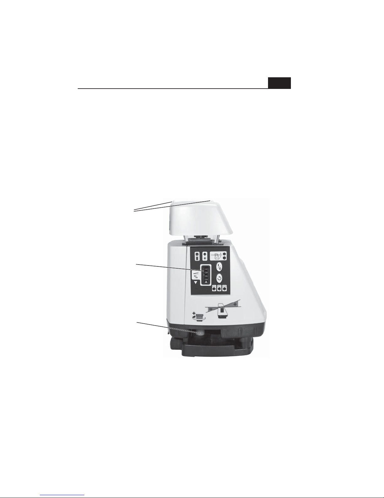
Follow the suggestions in the "initial setup guidelines" section (page 6).
Carefully aim the laser using the sights on the top cap. These sights indicate
the direction of slope. The front sloped face of the laser should be aimed
uphill (as shown on the graphic just above the slope knob).
Using the red slope adjustment knob, adjust the slope display to your
required slope. Note that if the laser has finished leveling and H.I. Alert has
become active (see initial controls and displays pg. 2/3) you will need to turn
the laser off, then on again to clear H.I. Alert.
Slope
alignment
sights
Slope
display
counter
Slope
adjustment
knob
Note: When using either AS2 model at slope settings over 14%, you will
need to tilt the tripod to allow the laser to reach the desired slope. By
aligning the laser so that one tripod leg is to the rear (down slope side), you
can shorten that leg to tilt the tripod head and the setup will remain stable.
Page 11
Slope Setup
9
The display reads in percent of grade (the number displayed is the units of
rise or fall per 100 units of run). A 2-1/2% slope (projecting upward from the
front of the laser) shows as 2.50 on the display. If a down slope is needed,
the display is set to the required slope and the rear of the laser is aimed in
the direction of slope. The graphic label just above the slope knob shows the
direction that upward or downward slopes are projected and the proper
direction to turn the knob to increase or decrease the slope.
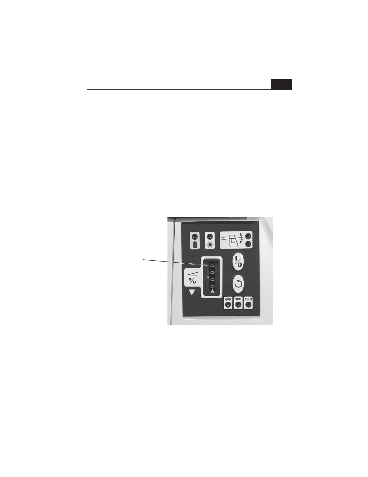
In order to be able to set an accurate zero percent slope (dead level), the
counter can be turned below zero. When the counter on either model is
turned to below zero, the upper counter digit will display a 9. This makes it
obvious that the slope is set incorrectly and should be changed to zero
(level), or to a positive slope setting. (see photo below)
This counter digit
displays a 9 when
the slope setting
goes below zero.
Re-set the slope to
zero (level), or to
a positive slope
setting when you see
a 9 displayed here.
Regularly check your setup against benchmarks. If none are present, set at
least two benchmarks of your own to monitor the accuracy of your setup.
The laser can be set at an offset to a ditch or excavation. Just be sure to
point the sights on the top cap parallel to the direction of the slope.
Page 12
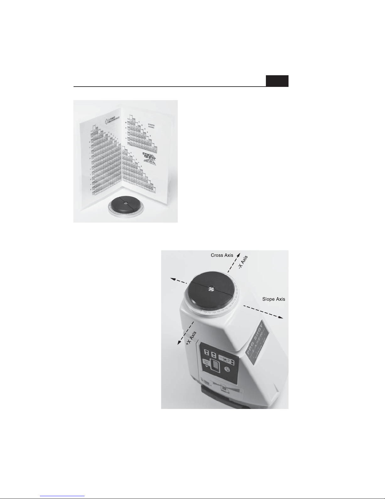
Compound Slope Setup
S2 Compound slope adapter kit
Next, follow the steps below
and on page 11:
10
Sites designed with compound slope
actually have just a single resultant
slope. When a site design has slope
in two directions, 90 degrees apart,
the optional model S2 Compound
Slope Adapter Kit can be used to
calculate and set the AS2 to the
proper angle and resultant slope.
NOTE: The S2 kit is standard with
the AS2 MAGNUM system.
In order to begin a compound slope
setup, the S1 Compound Slope
Adapter Kit must be installed on the
laser, following the instructions
included with the kit.
1. Determine the two slopes
for the site and the direction
of each slope. Set the
compound slope adapter
angle to zero (0) degrees
and aim the laser parallel to
the main slope on the site
(the main slope is the
steeper of the two slopes).
Be certain that the up-slope
direction of the laser is
aimed uphill on the main
slope. If there is any
question which is the
up-slope direction for the
laser, you can refer to the
label on the side of the laser
just above the slope knob.
-Y Axis
+Y Axis
Page 13
Compound Slope Setup
11
2. Using the compound slope chart supplied with the S2 kit, find the two
slopes for the site on the chart and follow their row and column until they
intersect. Remember that the main slope is the steeper of the two slopes.
The upper number in the box where the two slopes intersect is the angle to
set into the S2 adapter. The lower number is the resultant slope to dial into
the laser's slope counter. Note: The slope number is displayed with greater
precision than the slope counter increments.
3. Rotate the S2 adapter until it matches the angle determined with the slope
chart. Note: if, when standing behind the laser, the highest corner on the
site is to the right of the grade sight, you must rotate the adapter counter
clock-wise until you reach the proper reading. If the high corner is to the left,
you must rotate the adapter clock wise.
4. Turn the entire laser toward the uphill direction of the cross slope (toward
the highest corner on the site) until the slope alignment sight is once again
aligned parallel to the main slope. The laser is now at the proper angle.
5. To finish the setup, dial in the resultant slope determined from the chart
and go to work. Note: you can re-check the setup at any time by doing the
following: A. Verify the slope counter setting. B. Verify that the proper angle
is set into the compound slope adapter. C. Verify that the slope sighting slot
is parallel with the main slope direction. D. Verify that the uphill direction of
the laser is aimed toward the high corner of the site.
Always set at least two grade checking stakes that are 90 degrees apart so
that you can verify the laser setup from day to day on the site.
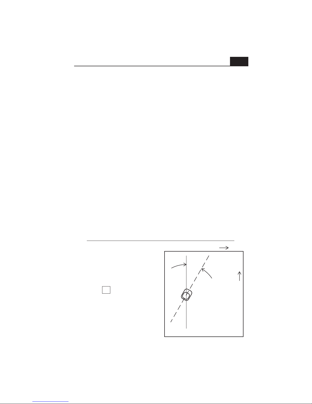
Compound slope example
1. Zero the compound slope adapter ring and
aim the laser parallel to the main slope, with
the up-slope direction of the laser aimed
up-hill on the site.
2. Look-up the intersection of the main slope
(.25) and the cross slope (.15) using the
slope chart. The box at the intersection.
looks like this:
3. Turn the adapter sighting slot 31° counter
clock-wise.
4. Turn the entire laser to re-align the sighting
slot parallel with the main slope. (the laser is
now aimed 31° toward the high corner).
5. Dial the resultant slope of .29% into the
slope counter. Setup is complete.
31
0.292
Cross slope= .15% up
High corner
31°
Resultant
slope .29%
Main slope= .25% up
Low corner
Page 14
Checking and Adjusting Calibration
12
Calibration is your responsibility, check it often.
Although both AS2 models are calibrated at the factory and are exceptionally
rugged lasers, it is well worth the effort to check calibration before you first
use your laser (after shipping) and then from time to time to ensure that you
are doing the highest quality work possible. Always check calibration if the
laser has been handled roughly.
Follow the steps below to check the calibration of the laser and make
necessary adjustments.
1. Attach the laser to a flat head tripod approximately 100 feet from a wall or
other stable vertical surface (a telephone pole or concrete building will work
well). We will call the vertical surface the target. The tripod head must be
level enough to allow you to turn the laser 360 degrees with minimal
re-leveling needed. Use the tripod leg adjustments to get the tripod head
level.
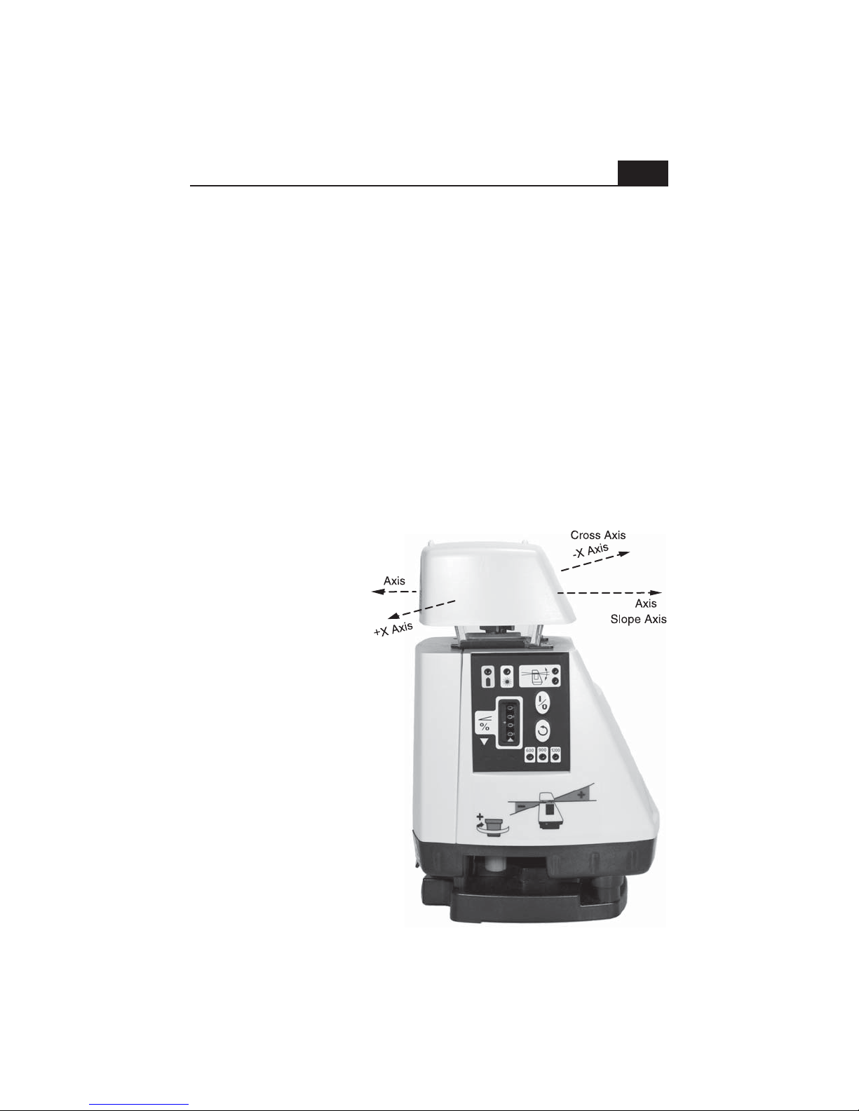
2. Rotate the entire
laser so that either
direction of the cross (X)
axis (see picture) is
aimed at the target.
3. Carefully set the
slope display counter to
-Y
+Y
00.00 (The red stripe on
the last counter digit
should be aligned with
the pointer). Turn the
laser on and allow it to
level.
4. Take the receiver to
the target and find the
height of the laser beam
by moving the receiver
up or down until you get
a display and/or tone.
Now, find the center of
the display and mark the
target, using the
receiver's beam center
notch as a guide.
Page 15

Checking and Adjusting Calibration
13
5. Return to the laser and rotate it 180 degrees. Allow the laser to re-level.
The opposite cross axis (X) direction is now aimed at the target. Find and
mark the laser beam height (see step 4).
6. The difference between the two marks (if any) is double the difference
between how the laser is calibrated and true level for the cross axis. Half
way between these two marks is true level. Make a long mark at true level.
If the difference between either outer mark and true level is within your
working tolerance, go on to step 10. If not, continue with the next step.
7. Remove the battery door and the rubber plug on the lower left side of the
battery holder. The four button switches inside control the calibration of the
laser. Each push of a button moves the calibration by approximately 3 arc
seconds (approx. 1/64” @100’ / .4mm @30m). A small screwdriver, allen
wrench or even a dull pencil can be used to press the buttons. The label
below the opening shows which direction each button will move each axis.
Press the + or - button corresponding to the X axis the number of times
estimated to bring the beam to the true level mark. Go to the target surface
and check the beam elevation. If the elevation is correct, go on to step 8. If
not, continue to press the button until the beam comes to level.
8. Check the cross axis adjustment by rotating the laser back to the first
direction and letting the laser re-level. Check that the reading is within the
needed tolerance of the true level mark.
9. Rotate the laser 90 degrees to aim the front of the slope axis at the target
(+Y axis). Allow the laser to re-level and check the reading at the target. If
the reading is on, or within tolerance of the true level mark, calibration is
complete. If not, continue on.
10. Verify the counter is set to exactly 00.00. Remove the battery door and
the rubber plug on the lower left side of the battery holder. The four button
switches inside control the calibration of the laser. Each push of a button
moves the calibration by approximately 3 arc seconds (approx. 1/64” @100’ /
.4mm @30m). A small screwdriver, allen wrench or even a dull pencil can be
used to press the buttons. The label below the opening shows which
direction each button will move each axis. Press the + or - button
corresponding to the Y axis the number of times estimated to bring the beam
to the true level mark. Go to the target surface and check the beam
elevation. If the elevation is correct, put the rubber plug back in. If not,
continue to press the button until the beam comes to level.
Calibration is now complete.
Page 16
R7 • AS2 System Receiver
14
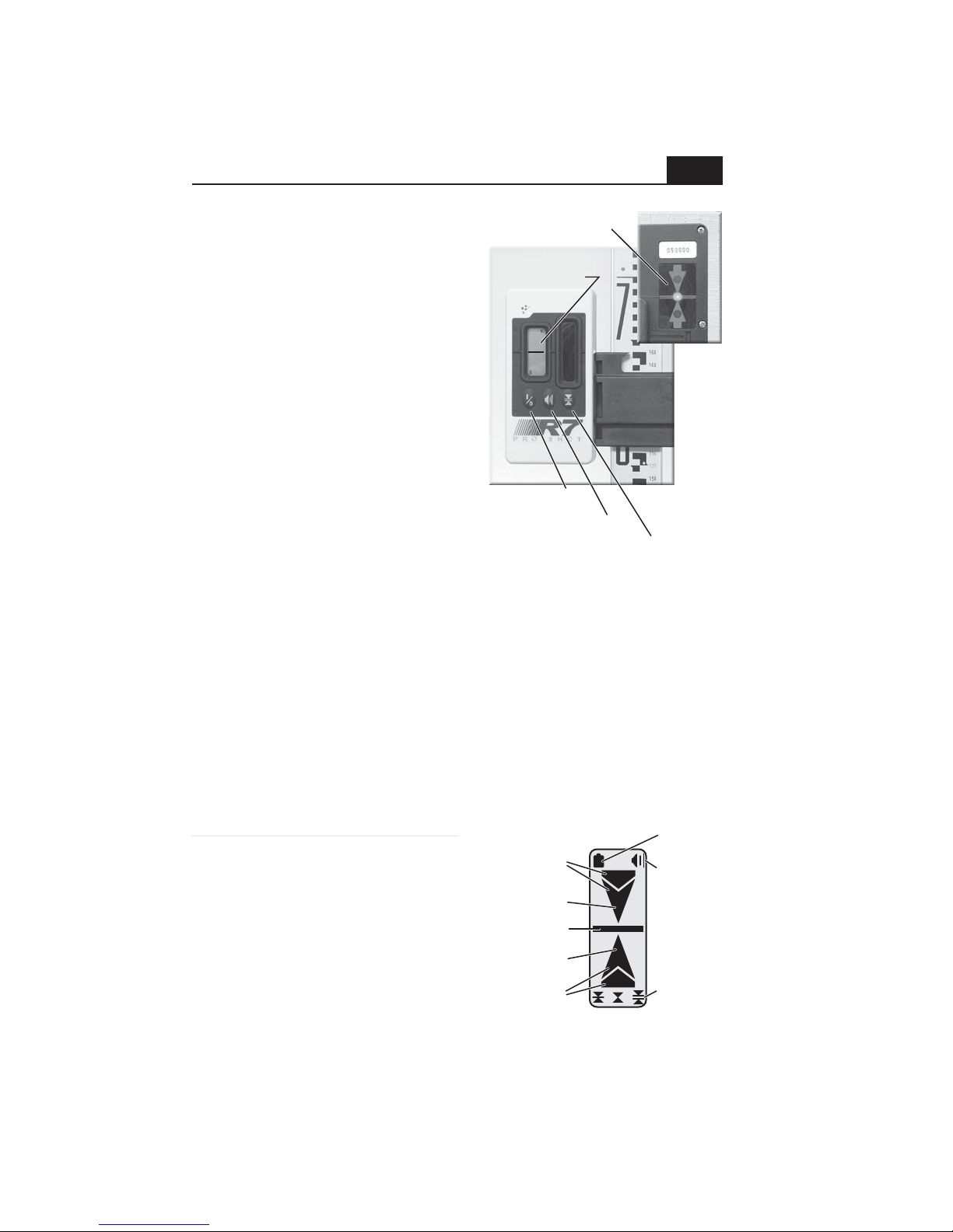
The R7 senses the plane of laser light
Rear display
projected by the AS2 and indicates a
height position relative to the plane (high,
low, or on grade). The R7 uses a five
Five channel
front display
channel front LCD to display height
information and a three channel rear LED
display. Along with the visual displays,
an audio tone also indicates when the
receiver is high, low, or on grade. When
the R7 is exactly centered at the beam
height, an on grade "bar" indication is
displayed. If the R7 is high or low, an
"arrow" shows the direction to move the
R7 in order to get an on grade indication.
The R7 has three control switches, power
on/off, tone high/low/off and on-grade
accuracy select. Pressing the power
switch activates the R7. The audio tone
Power switch
Volume switch
Accuracy switch
will sound and the LCD display will show the tone and accuracy icons. The
R7 is ready to operate in standard accuracy with loud tone. Pressing the
volume switch once changes to low volume, twice turns the volume off.
When the volume is off, there will still be a single tone the first time the R7
senses a laser signal. Pressing the accuracy switch once changes to the
coarse setting, twice changes to fine. The R7 automatically turns off if no
laser beam strikes are received for twelve minutes. The R7 is powered by a
9 volt battery that lasts approximately 60 hours. When the battery is nearly
used up, the low battery indicator will be displayed. To replace the battery,
locate the battery door on the back of the housing and slide the door toward
the bottom of the receiver. Remove the battery from the compartment (you
may need to tap the R7 on your palm to free the battery). Replace the
battery following the diagram molded on the battery door.
Specifications and display icons
Reception Height ............
Reception Angle ..............
Standard mode accuracy
Coarse mode accuracy ...
Ultra-fine mode accuracy
Power Supply ..................
Battery life (alkaline) .......
Automatic Shut Off ........
Environmental ...............
Rotation Compatibility ...
Mount Clamping Range
2 inches (50mm)
120 degrees
±1/16 in. (±1.6mm) nominal
±1/8 in. (±3.2mm) nominal
±1/64 in. (±.4mm) nominal
9 volt battery
60 hours continuous
After 12 min. (no laser strikes)
Sealed against dust and water
250 to 850 R.P.M.
5/8in to 2-1/2in (16mm-65mm)
High coarse
(both)
High fine
On Grade bar
Low fine
Low coarse
(both)
Low batt.
To ne
volume
Accuracy
L - R: std.,
fine, coarse
Page 17
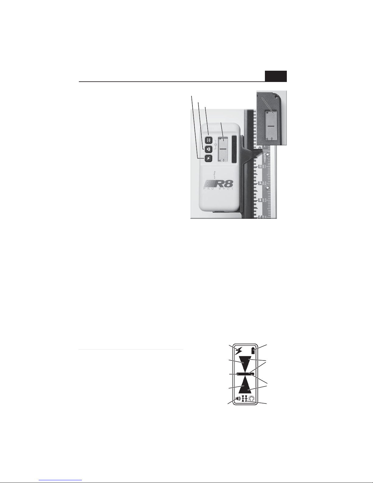
R8 • AS2 MAGNUM System Receiver
Rear display
The R8 senses the plane of laser light
projected by the AS2 MAGNUM and
indicates a height position relative to
the plane (high, low, or on grade).
The R8 uses five channel front and
rear LCDs to display height
information. Along with the visual
displays, an audio tone also indicates
when the receiver is high, low, or on
grade. When the R8 is exactly
centered at the beam height, an on
grade "bar" indication is displayed. If
the R8 is high or low, an "arrow"
shows the direction to move the R8 in
order to get an on grade indication.
Power
Volume
Accuracy
Five channel
front display
Rear display
Rear display
15
The R8 has three control switches,
power on/off, tone high/low/off and
R8 shown on optional cut/fill rod
on-grade accuracy select. Pressing
the power switch activates the R8. The audio tone will sound and the LCD
display will show the power, tone and accuracy icons. The R8 is ready to
operate in standard accuracy with loud tone. Pressing the volume switch
once turns the volume off, twice changes to low volume. When the volume is
off, there will still be a single tone the first time the R8 senses a laser signal.
Pressing the accuracy switch once changes to the coarse setting (note:
display is 3 channels in coarse), twice changes to fine. The R8 automatically
turns off if no laser beam strikes are received for 30 minutes. The R8 is
powered by two AA cell batteries that last approximately 70 hours. When the
battery is nearly used up, the low battery indicator will be displayed. To
replace the batteries, locate the battery door on the lower back of the
housing and open the latch using a coin. Replace batteries following the +
diagram on the housing.
Specifications and display icons
Reception Height ............
Reception Angle ..............
Standard mode accuracy
Coarse mode accuracy ...
Ultra-fine mode accuracy
Power Supply ..................
Battery life (alkaline) .......
Automatic Shut Off ..........
Environmental .................
2 inches (50mm)
90 degrees
±1/16 in. (±1.6mm) nominal
±1/8 in. (±3.2mm) nominal
±1/32 in. (±.8mm) nominal
2 AA cell batteries
70 hours continuous
After 30 min. (no laser strikes)
Sealed against dust and water
Power
High coarse
On Grade bar
Low coarse
Tone volume
Low batt.
High fine
(both)
Low fine
(both)
Accuracy
Page 18

Maintenance And Troubleshooting
Calibration • There is no set interval for calibrating either AS2 model, but
calibration should be checked from time to time in order to ensure that the
highest possible quality of work is being done. Calibration should always be
checked if the laser has been handled roughly or shipped.
Batteries • Occasionally remove the batteries and check the contacts for
corrosion. Alkaline batteries will last far longer than carbon batteries. If you
use rechargeable batteries, be careful to never charge alkaline or carbon
batteries. Never run the laser from the charger unless there are
rechargeable batteries installed. Keep a spare set of batteries in the carrying
case to avoid down time.
Laser output windows • Regularly check the output windows for dust and
dirt. Dust can be removed with a camera brush or clean compressed air.
Control panel and exterior • Clean the control panel and the other exterior
surfaces of the laser with a soft damp cloth.
Caution! • Never store the laser in a carrying case that is wet inside.
Moisture can get inside the laser this way. Should this happen, remove the
battery cover and place the laser in a warm area until it is completely dry.
16
Troubleshooting
The laser will not operate, there is no obvious damage • If the low battery
indicator is on, or you suspect the batteries may be dead, replace the
batteries. Check the battery contacts to be sure that they are clean.
The receiver shows an on-grade at two different heights • Check the jobsite
for windows or mirrored surfaces that might be reflecting the laser and
causing the other reading. Check for others on the site using a rotary laser.
The laser was knocked over • Visually check the optics for damage. Inspect
the laser for any other physical damage. Use the receiver to check that the
laser is transmitting. Check the calibration and adjust as needed.
The laser only works at short distances • Check the output windows for
heavy dust or moisture. Remove dust with a camera brush or blow off gently
with clean compressed air. Allow moisture to dry.
The receiver does not indicate "on grade" at long distance • Be sure you are
within the max distance specification from the laser. Check the windows that
surround the rotating mirror on the laser for dust or moisture. Remove dust
with a camera brush or blow off gently with clean compressed air. Allow
moisture to dry.
Page 19

Warranty
17
Guardian 36 month warranty coverage
The AS2 and AS2 MAGNUM laser transmitters, along with the R7 receiver, are
warranted for thirty-six (36) months from the date of new equipment purchase from an
authorized dealer. The R8 receiver is warranted for twenty-four (24) months. During
the warranty period, Laser Reference, or its authorized service center, will repair or
replace, at Laser Reference's sole discretion, laser transmitters or receivers, free of
charge, (except for transportation costs) if the products are found by Laser
Reference, or its authorized service center, to be defective in either materials or
workmanship. The Guardian 36 month warranty also covers the internal leveling
mechanism and internal optics (parts only, not labor) against damage from any cause.
Maintaining the calibration of the product is not the responsibility of Laser Reference
or its authorized service centers. If service is needed, the product(s) must be sent
FREIGHT PREPAID to the nearest authorized service center or to Laser Reference.
Specifications
Range with receiver • AS
2
MAGNUM .......
AS
Leveling accuracy • AS
2
2
........
.....
AS2 MAGNUM .......
Slope Capability ....................
Compound slope capability ...
2
MAGNUM .......
AS
Self-Leveling Range ..............
2
Rotation speed • AS
2
MAGNUM .......
AS
.............
Power Supply ........................
Rechargeable Batteries .........
Run Time (continuous) • AS
2
MAGNUM .......
AS
Automatic Shut-off .................
Environmental .......................
Operating Temp. • AS
2
AS
MAGNUM .......
2
..........
Storage Temperature ............
2
Laser rating ....................
AS
2
MAGNUM Laser rating ..
AS
Height / Weight ......................
1000' rad., 2000' dia. (305m/610m)
1650' rad., 3300' dia. (500m/1000m)
±14 arc seconds (2.0mm per 30m)
(.080" per 100')
±10 arc seconds (1.5mm per 30m)
(.060" per 100')
-
25%, single axis, .01% increments
0
S2 compound slope kit optional
S2 compound slope kit included
±4 Degrees
600rpm
600, 900, 1200rpm (selectable)
Four C-cell batteries (alkaline std.)
Available option (NiMh)
2
.
115 hrs. (alkaline) / 95 hrs. (NiMh)
70 hrs. (alkaline) / 55 hrs. (NiMh)
If off-level for more than 3 min.
Dust and water resistant (IP55)
14ºf to +122ºf (-10ºc to +50ºc)
14ºf to +140ºf (-10ºc to +60ºc)
-40ºf to +140ºf (-40ºc to +60ºc)
CDRH Class 2 • IEC 825-1 Class 2
CDRH Class 3A • IEC 825-1 Class 3R
9.7in (24.5cm) / 4.4lbs (2.0kg)
Page 20
pro
laser
pro
laser
California
California
•
•
USA
USA
Laser Reference, Inc.
151 Martinvale Lane
San Jose, CA 95119
•
USA
Toll Free (USA)
Telephone
Email
Fax
Web
• +
1.800.238.0685
• +
1.408.361.0220
• +
1.408.361.3180
•
www.pro
•
sales@pro
shot laser
shot laser
.com
.com
Customer information
Laser Serial number _____________________________
Receiver S/N __________________________________
Date of purchase _______________________________
Part No. 010-6065 Version 2.0
 Loading...