

Page 1
Important Safety Instructions
SAVE THESE INSTRUCTIONS. This manual contains important SAFETY WARNINGS and
OPERATING INSTRUCTIONS for the Pro Series pumps. You will need to refer to it before
attempting any installation or maintenance.
ALWAYS keep these instructions with the unit so that they will be easily accessible.
Failure to read and follow these warnings and instructions could result in property
damage, serious injury, or death.
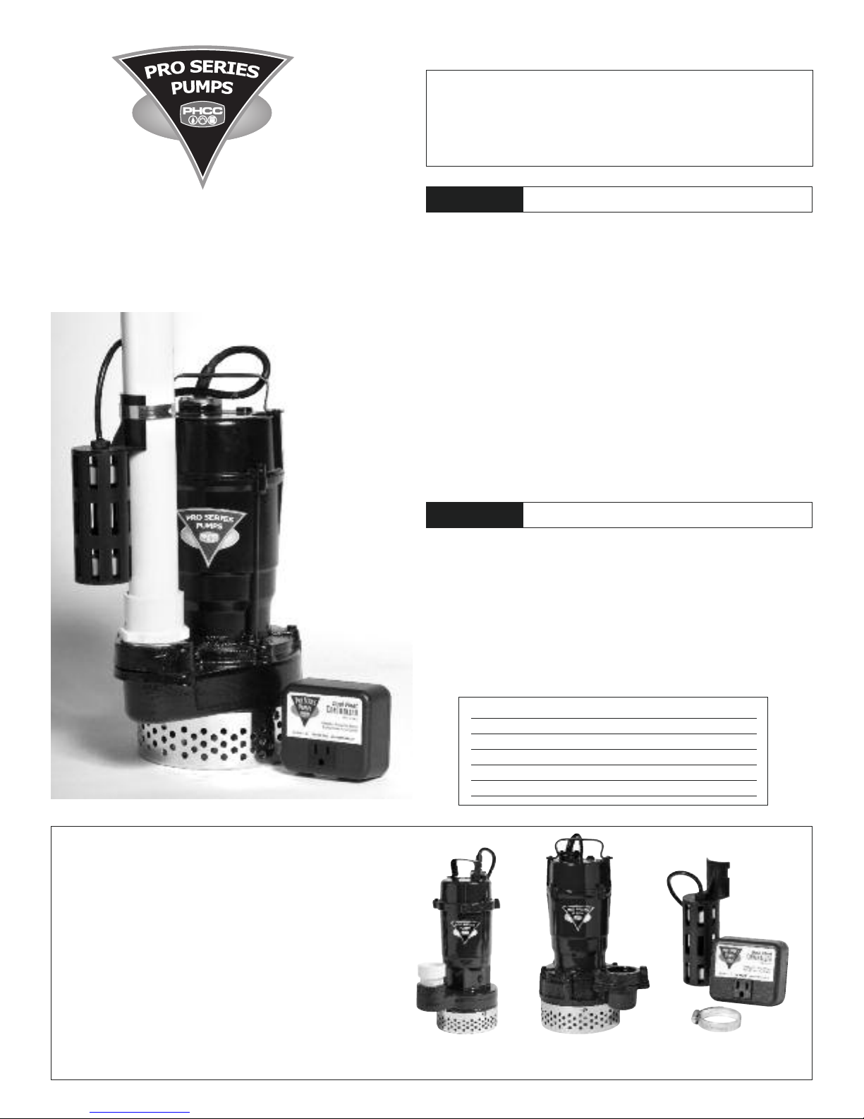
Sump Pumps
Instruction Manual &
Safety Warnings
WARNING
• ALWAYS disconnect the pump from the power source before servicing or making
adjustments.
• NEVER handle the pump or motor with wet hands or when standing on a wet or damp
surface while the pump is plugged into the power source.
• MAKE SURE THERE IS A PROPERLY GROUNDED RECEPTACLE AVAILABLE. This pump is
wired with a 3-prong grounded plug. To reduce the risk of electric shock, be certain that
it is only connected to a properly grounded, 3-prong receptacle (preferably with ground
fault circuit interrupt). If you have a 2-prong receptacle, have a licensed electrician
replace it with a 3-prong receptacle according to local codes and ordinances.
• NEVER bypass grounding wires or remove the ground prong from the plug.
• DO NOT use an extension cord. The electrical outlet should be within the length of the
pump’s power cord, and at least 4 feet above the floor level to minimize potential
hazards from flood conditions.
• DO protect the electrical cord from sharp objects, hot surfaces, oil, and chemicals. Avoid
kinking the cord.
• MAKE SURE the supply circuit has a fuse or circuit breaker rated to handle the power
requirements noted on the nameplate of the pump.
CAUTION
• DO NOT use the power cord or strain relief to carry the pump. Use the pump handle.
• DO NOT expose the control unit to rain or snow.
• DO NOT operate the pump or control unit if it has been damaged in any way.
• DO NOT use sump pumps in pits handling raw sewage, salt water, or hazardous liquids.
• DO NOT disassemble the pump or control unit. When service is required, contact
Glentronics technical support at 800-991-0466, option 3. Return the product to the
manufacturer for any repairs at the following address:
Risk of electric shock. To reduce this risk, observe the
following precautions.
To reduce the risk of hazards that can cause injury or
property damage, observe the following precautions.
Glentronics, Inc.
640 Heathrow Drive, Lincolnshire, IL 60069
Items included:
Pump
Dual float and controller
Stainless steel hose clamp
2" x 1-1/2" reducer adapter
(on 3/4 HP pump only)
You may also need:
1-1/2” or 2" rigid PVC pipe to
connect to the existing plumbing
A check valve or union
PVC pipe cleaner and cement
A surge protector
Note:
The 1/2 HP pump will accomodate a 2" discharge pipe. However, most
homes have 1-1/2" pipes. Therefore we have included a 2" x 1-1/2"
reducer adapter with this pump. You may replace your 1-1/2" discharge
pipe with a 2" discharge pipe, and a 2" adapter to obtain the optimum
gallons per hour.
1-1/2”
discharge
Specifications 1/3 HP Model ST1033 1/2 HP Model ST1050
GPH @ 0’ 4100 5300
GPH @ 10’ 2770 3630
Pump diameter 7.375” 9.75”
Volts 115V, 60Hz 115V, 60Hz
Amps 3.8 4.8
2”
discharge
1/3 HP Pump
ST1033
1/2 HP Pump
ST1050
The Dual Float
& Controller
Page 2

NOTICES
P
UMP
WIRE
AIR BLEED
HOLE
F
LOOR
JOIST
SLOPE
PIPE
DOWN
S
URGE
PROTECTOR
DISCHARGE
PIPE
GATE
VALVE
UNION/CHECK
VALVE
PRO SERIES
PUMP
DOUBLE
FLOAT
BRICKS
DRAIN TILE
FLOAT WIRE
DUAL FLOAT CONTROLLER
PLUGGED INTO
AC OUTLET
PIT COVER
Controller
D
ual Float
C
onsider a Pro Series Battery
B
ackup Sump Pump System
Glentronics,Inc. 800.991.0466 www.stopflooding.com
ModelNo.DFC1
SURGE
PROTECTOR
DISCHARGE
PIPE
GATE
VALVE
DUAL FLOAT CONTROLLER
PLUGGED INTO
AC OUTLET
PUMP
WIRE
FLOAT
WIRE
Controller
Dual Float
Consider a Pro Series Battery
Backup SumpPump System
G
lentronics, Inc. 800.991.0466 www.stopflooding.com
M
odel No. DFC1
• The control unit must receive 115V AC +/- 5% and 60 Hz from the AC outlet.
• These primary pumps will not provide protection during a power outage. With the
risk of property damage from high water levels, the addition of a Pro Series battery
backup sump pump system is highly recommended.
• After the initial installation, be sure to check the operation by filling the sump
with water and observing the pump operation through one full cycle.
• For continuous duty operation, the pump must be submerged at least 3/4 of the
depth of the pump at all times.
• In instances where the discharge line is exposed to freezing temperatures, the pipe
must be sloped downward so any remaining water will drain out. Failure to do so
will prevent water from exiting the sump and damage the pump if the line freezes.
Installation Instructions
Prior to Installation
1. Visually inspect your pump. Products may be damaged during shipping. If the
product has been damaged, contact your place of purchase or Glentronics, Inc.
before installation.
2. Thoroughly read the instructions provided to learn specific details regarding
installation and use. This manual should be retained for future reference.
WARNING
1. Use a pit that conforms to all local
codes and is large enough to
accommodate the pump and float
switch. The minimum requirements for
the 1/3 HP pump with the double
float assembly are 8⬙ in diameter and
14⬙ deep, for the 1/2 HP pump they
are 10" in diameter and 16" deep.
However, larger sump pits are
preferred, since they will extend the
discharge cycle and reduce the
number of times the pump turns on.
2. Clean the pit of all debris. The
pump’s strainer must be kept clear.
3. The pump should not be set directly
onto a clay, earthen, or sand base.
You may install bricks or blocks under
the pump to provide a solid base.
4. The pump should be level.
5. Install discharge plumbing according
to local, regional and state codes.
Rigid PVC pipe is recommended.
6. An in-line check valve is
recommended to prevent back-flow.
This check valve is mandatory when sharing a discharge line with another pump
(i.e. a back-up pump or a second primary pump).
7. Install a gate valve or ball valve if required by any codes.
8. The pipe must be positioned in a downward slope so any remaining water will drain
9. If you are replacing an old sump pump:
away. Failure to do this will prevent water from exiting the pit and damage the
pump if the line freezes.
(a) Unplug the pump from the outlet.
(b) Loosen the check valve or rubber union by
unscrewing the bottom hose clamp. (If the
existing system is installed without a check
valve or rubber union, saw the pipe apart above
the sump pit.)
(c) Remove the old pump and unscrew the pipe and
adapter.
This installation must be in accordance with the National
Electric Code and all applicable local codes and ordinances.
9B
9C
9D
9F
(d) If the adapter fits into the new pump, screw the pipe into the pump. If not, cut
a piece of rigid PVC pipe and connect it to the new adapter by cleaning and
cementing the two pieces together. (Follow the instructions on the PVC cleaner
and cement.)
(e) Loosen the enclosed stainless steel hose clamp by turning the screw
counterclockwise and slip it over the pipe on top of the pump.
(f) Hold the float switch against the discharge pipe so the cage is below the bracket.
(g) Position the bottom of the float at the height you want the pump to activate and
turn the screw clockwise to tighten the hose clamp, but do not tighten it
completely at this time.
(h) Lower the pump into the sump by the handle.
(i) To avoid debris pouring into the float, it should be positioned on the side of the
discharge pipe opposite the drain tile. Note: It is desirable to mount the float
below the drain tile that empties into the pit. Mounting it above the drain tile
would allow water to fill the drain tile before the pump is activated. (See diagram).
(j) Once the switch is in the desired position, tighten the hose clamp.
(k) Connect the pipe on the pump to the existing discharge pipe with a rubber union
or check valve and tighten the hose clamps securely.
Connecting the Pump and Controller
WARNING
Dual Float Controller
Plug the control box into a properly
grounded, 3-prong receptacle (preferably
with ground fault circuit interrupt), then
insert the pump plug into the receptacle
on the control box. You should provide
additional protection for the control unit
by using a surge protector.
For a neater installation, secure the power
cord and the float switch cord to the
discharge pipe with wire ties or hose
clamps. Keep the cords separated from
each other on opposite sides of the pipe.
Completing the Installation
1. After the initial installation, be sure to check the pump operation by filling the sump
with water and observing the pump through one full cycle. The pump should run for
10 seconds after the lower float drops. Note: When the pump activates, it should have
a “normal pumping” sound. Any abnormal sound, vibration, or lack of output is the
signal of a problem. Stop the pump and refer to the
troubleshooting guide.
2. Replace the pit cover making sure not to pinch or crimp
the pump wire with the cover. The pit cover either has
a ‘hole punch’ that will allow the cord to be passed
through or one can be drilled in the cover.
Make sure the outlet is single phase, 115V and 60HZ
for all the pump installations.
Product Operation
Dual Float Switch
The dual float switch contains two large floating rings
enclosed within a protective cage. Water will lift the
2
Page 3

bottom float by a1⁄4⬙, which will activate the pump. If for any reason the lower float
PUMP
WIRE
PIT COVER
CHECK
VALVE
F
LOAT
W
IRE
FLOAT
WIRE
MAIN
A/C PUMP
A
/C FLOAT
S
WITCH
BATTERY
BACKUP PUMP
BACKUP PUMP
FLOAT SWITCH
BATTERY
D
RAIN TILE
B
ATTERY
C
ABLE
AC
OUTLET
BACKUP SYSTEM
CONTROL UNIT
P
UMP
W
IRE
D
UAL FLOAT CONTROLLER
PLUGGED INTO
AC OUTLET
SURGE
PROTECTOR
Controller
Dual Float
C
onsider a Pro SeriesBattery
B
ackupSump Pump System
Glentronics, Inc. 800.991.0466 www.stopflooding.com
Model No.DFC1
does not activate the pump, the water will rise and activate the second switch. As the
pump evacuates the water from the pit the floats will drop. The pump will run for an
additional 10 seconds to extend the cycle after the lower float drops. Note: When
mounting the float switch, position the bottom of the cage at the height you want the
pump to activate.
Dual Float Controller
The Dual Float Controller will activate the pump
when either float is lifted, and then shuts off
automatically 10 seconds after the float drops.
Plug the pump cord into the piggyback switch
on the control unit.
Operating the Pump in a Continuous
Duty Application
Dual Float Controller
The Pro Series pumps are rated for continuous duty and may be used in applications
requiring continuous pumping including fountains, ponds, etc. For use in any
continuous duty application the pump should be plugged directly into the wall outlet
without the use of the controller. The outlet must be a single phase properly grounded
3-prong receptacle, 115V, 60HZ (preferably with ground fault circuit interrupt). For
continuous duty operation, the pump must be submerged at least 3/4 of the depth of the
pump at all times.
Maintenance Check List
Maintenance should be performed 1-2 times per year.
1. Remove all debris from the bottom of the pit.
2. Remove all debris floating in the water.
3. Remove all debris from the float switch cage.
4. Fill the pit with water. Make sure pump turns on at the intended level.
5. While the pump is running, make sure pump is evacuating water at a good pace.
Backup Installation
When the power goes out, the Pro Series AC sump pumps will not operate. For
protection during a power outage, a Pro Series battery backup system
can be installed. There are three systems with matching batteries that will provide
protection. The illustration below is an example of a typical battery backup
installation.
Visit our website www.stopflooding.com for more information about the Pro Series
AC sump pumps and battery backup sump pump products.
Warranty
GLENTRONICS, INC. warrants to the end purchaser that its pumps, switch and control unit products are free from defective materials and workmanship for the periods indicated below:
All parts and labor (excluding installation) for a period of:
The defective product must be returned directly to the factory, postage prepaid with the original bill of sale or receipt to the address listed below. GLENTRONICS, INC., at its option,
will either repair or replace the product and return it postage prepaid.
Conditions
The unit must be shipped, freight prepaid, or delivered to GLENTRONICS, INC. to provide the services described hereunder in either its original carton and inserts, or a similar package
affording an equal degree of protection.
The unit must not have been previously altered, repaired or serviced by anyone other than GLENTRONICS, INC., or its agent; the serial number on the unit must not have been altered
or removed; the unit must not have been subject to accident, misuse, abuse or operated contrary to the instructions contained in the accompanying manual.
The dealer's dated bill of sale, or installers invoice must be retained as evidence of the date of purchase and to establish warranty eligibility.
This warranty does not cover product problems resulting from handling liquids hotter than 104 degrees Fahrenheit, handling inflammable liquids, solvents, strong chemicals or severe
abrasive solutions; user abuse; misuse, neglect, improper maintenance, commercial or industrial use; improper connection or installation, damages caused by lightning strikes; excessive
surges in AC line voltage; water damage to the controller; other acts of nature, or failure to operate in accordance with the enclosed written instructions.
GLENTRONICS, INC. WILL NOT BE LIABLE FOR ANY INCIDENTAL, SPECIAL OR CONSEQUENTIAL DAMAGES FOR BREACH OF ANY EXPRESS OR IMPLIED WARRANTIES ON THIS PRODUCT. SOME
STATES DO NOT ALLOW FOR THE EXCLUSION OR LIMITATION OF CONSEQUENTIAL OR INDIRECT DAMAGE. THE ABOVE LIMITATION MAY NOT APPLY TO YOU. THIS EXPRESS WARRANTY SHALL
BE EXCLUSIVE AND IS IN LIEU OF ALL OTHER WARRANTIES, WRITTEN OR ORAL, EXPRESS OR IMPLIED, INCLUDING, BUT NOT LIMITED TO ANY WARRANTY OF MERCHANTABILITY OR FITNESS
FOR A PARTICULAR PURPOSE. THIS CUSTOMER'S EXCLUSIVE REMEDY FOR BREACH OF THIS WARRANTY, OR OF ANY IMPLIED WARRANTY NOT EXCLUDED HEREIN, SHALL BE LIMITED TO
REPAIR OR REPLACEMENT OF THE PRODUCT.
• 3 years from the date of purchase on the 1/3 HP pump, when used intermittently as a sump pump
• 5 years from the date of purchase on the 1/2 HP pump, when used intermittently as a sump pump
• 1 year from the date of purchase on all pumps, when used in continuous duty operations such as fountains or ponds
For information or service contact:
Glentronics, Inc., 640 Heathrow Drive, Lincolnshire, IL 60069 800-991-0466
Model No. _________________________ Purchase Date _________________________
3
Page 4

1806058
© Glentronics, Inc. 2008
4
 Loading...