

Page 1
INSTRUCTION MANUAL
15K Fifth Wheel Hitch
DEALER/INSTALLER:
(1) Provide this Manual to end user.
(2) Physically demonstrate hitching and unhitching procedures in this Manual to end user.
(3) Have end user demonstrate that he/she understands procedures.
END USER:
(1) Read and follow this Manual every time you use hitch.
(2) Save this Manual and Hitch Warning Hang Tag for future reference.
(3) Pass on copies of Manual and Hitch Warning Hang Tag to any other user or owner of hitch.
(4) Never remove hitch warning decals as shown on the cover of this manual. If damaged, contact Cequent Towing Products (1888-521-0510) for free replacement decals.
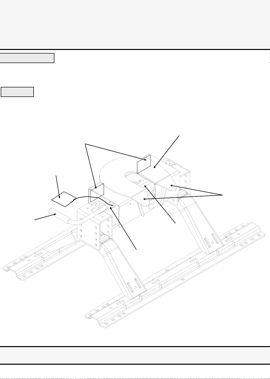
Skid Plate
Warning Decals (Front of Hitch)
Hitch Warning Hang Tag
Hitch Handle
Ramp
Locking Bar
Handle Tab
PATENTS PENDING
For Installation Assistance or Technical Help, Call 1-888-521-0510
30056IN – 21DEC05I PCN8397 ©2006 Cequent Towing Products Litho in USA 1
Page 2
WARNING:
Failure to follow these instructions may result in death or serious injury!
INDEX
1. GUIDELINES FOR MATCHING TOW VEHICLE AND TRAILER P. 2
2. ASSEMBLY INSTRUCTIONS P. 4
3. BEFORE EACH TRIP P. 5
4. HITCHING PROCEDURE P. 5
5. PULL TEST P. 8
6. UNHITCHING PROCEDURE P. 8
7. MAINTENANCE P. 9
8. Cequent Towing Products THREE YEAR LIMITED WARRANTY P. 23
9. GENERAL CHASSIS MOUNTING INSTRUCTIONS P. 10
10. BASE RAIL APPLICATIONS
•GM ‘99 SILVERADO, SIERRA (NOT SIERRA CLASSIC) MODELS (AMBER TURN SIGNALS),
GM ‘00 AND NEWER SILVERADO, SIERRA MODELS (AMBER TURN SIGNALS)
INCLUDING HD MODELS P. 12
•CHEVROLET/GMC 88-98, 92-98 4-DOOR, ‘99 SILVERADO SIERRA CLASSIC
(TAPERED FRAME, RED SIGNALS)
•CHEVROLET ‘73-’87, ‘73-’92 4-DOOR (GMC) (34” STRAIGHT, OUTSIDE SHOCK ABSORBERS) P. 14
•CHEVROLET ‘73-’87, ‘73-’92 4-DOOR (GMC) (34” STRAIGHT, INSIDE SHOCK ABSORBERS) P. 15
•FORD ‘97 & NEWER F-150 AND F-250 8500 GVW OR UNDER P. 16
•FORD F-150 & F-250 THROUGH ‘96, ‘97 F-250 OVER 8500 GVW, F-350 THROUGH ‘97
NOT SUPERDUTY, ‘99 & NEWER F-250 AND F-350 SUPERDUTY
•DODGE ‘02 AND NEWER 1500 P. 18
•DODGE ‘94-’01 1500, ‘94 TO ‘02 2500/3500 (FULL SIZE, SHORT AND LONG BOX) P. 19
•DODGE THROUGH ‘93 (FULL SIZE) P. 20
•DODGE ‘94 DAKOTA & NEWER P. 21
•TOYOTA TUNDRA 2000 & NEWER (LONG BOX ONLY) P. 22
P. 13
P. 17
GUIDELINES FOR MATCHING HITCH TRUCK AND TRAILER
WARNING:
•Trailer and its contents together must not exceed truck, hitch and/or trailer tow ratings.
•Towing vehicle must have a manufacturer’s rated towing capacity equal to or greater than
the gross trailer weight (dry weight of the trailer plus payload of the trailer). (See Fig. 1)
•Gross weight of trailer must not exceed 15,000 pounds.
•King pin weight must not exceed 3750 pounds (See Fig. 2). If in doubt, have king pin weight
measured by qualified facility.
Fig. 1
1. This hitch is designed for use with recreational fifth wheel trailers only. Hitch applications other than recreational fifth wheel trailers
must be approved in writing by Towing Product’s Engineering Department.
2. Use only a SAE 2-inch kingpin with this Fifth Wheel Hitch.
3. Approximately 15%-25% of trailer weight should be on hitch (Pin Weight). See Fig. 2
FACTORY TRAILER + FULL WATER TANKS + CARGO, ETC.
= GROSS TRAILER WEIGHT
Fig. 2
15-25%
GROSS TRAILER
WEIGHT
(PIN WEIGHT)
GROSS TRAILER WEIGHT
30056IN – 21DEC05I PCN8397 ©2006 Cequent Towing Products Litho in USA 2
75-85%
GROSS TRAILER
WEIGHT
Page 3
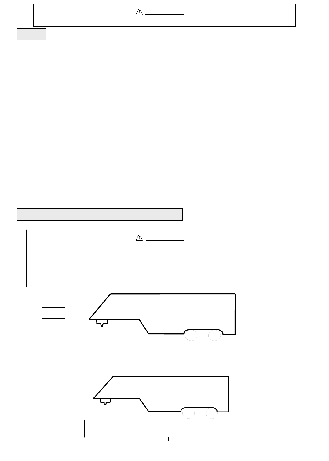
4. Trucks come in many different configurations. This hitch is designed for use in light trucks such as the Ford F-Series, the Chevy
Silverado and the Dodge Ram. This hitch is recommended for use with long bed (8ft) light trucks for the best combination in trucktrailer turning clearance.
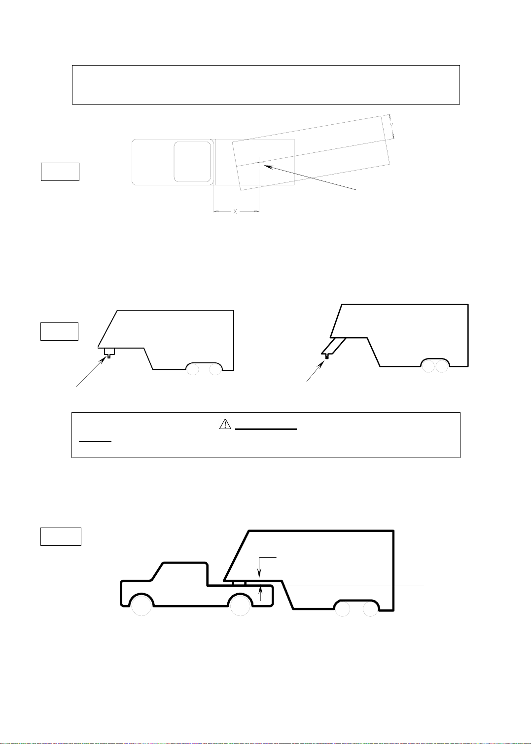
Rule of thumb: The distance from the back of the truck cab to the center of the rear truck
axle (“X” in Fig. 3), should be approximately 4 inches greater than one-half
the trailer width (“Y” in Fig.3)
RV TRAILER
Fig. 3
TRUCK
5 . If a short bed pickup (less than 8 ft. but longer than 6 ft.) is to be used for towing, Cequent Towing Products recommends the
trailer be equipped with an extended pin box to help gain additional truck - trailer turning clearance (See trailer manufacturer for
options) (See Fig. 4). It also may be helpful to add a Kwik-Slide for increased turning clearance for low speed, non-highway
maneuvering.
Fig. 4
Conventional Pin Box
Extended Pin Box
KING PIN
WARNING:
Do Not install this fifth wheel hitch on or attempt to tow with a short bed pickup
truck that has a bed shorter than 6 ft.!
6. The height of the hitch and the pin box should be adjusted so the trailer is approximately level as it is towed. Allow approximately
6 inches clearance between the top of the pickup walls and the underside of the front of the trailer for pitch and roll of the trailer.
(See Fig. 5). Allow more clearance between pickup walls and trailer for off road use.
Fig. 5
Approximately 6 Inches
Level Trailer
30056IN – 21DEC05I PCN8397 ©2006 Cequent Towing Products Litho in USA 3
Page 4
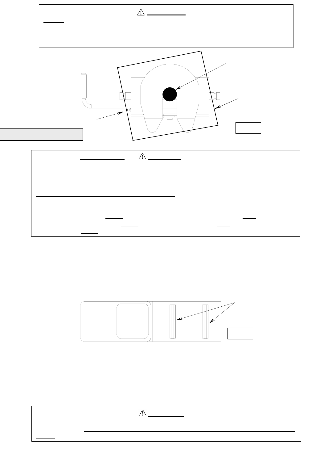
Do Not use this hitch for towing a trailer with a pin box that could come into contact
with or interfere with the pad lock or the handl e tab when turning! (See Fig. 6) If
the pin box contacts the hitch handle, tab or its lock when turning, the trailer may
become unhitched.
PAD LOCK
ASSEMBLY INSTRUCTIONS
•Connection for trailer wiring should be in the side of the truck bed between the driver’s
seat and the wheel well for the back truck axle
•Installation of connection rearward of the wheel well may result in user plac ing body
between truck and trailer. WHENEVER POSSIBLE, AVOID PUTTING BODY UNDER
TRAILER OR BETWEEN TRUCK AND TRAILER!
•If you need to place any part of your body under trailer or between truck and trailer:
WARNING:
KING PIN
BOTTOM OF PIN BOX
Fig. 6
WARNING:
• All trailer tires MUST
be blocked in front and behind each tire AND
• Trailer landing gear MUST be resting on firm ground AND
• Truck MUST be stationary, in park, with emergency brake on!
1. Reference Fig. 19 on back page. Numbers in parentheses refer to parts in Fig. 19.
2. 5th Wheel Kit is contained in one carton plus two base rails sent loose. Unpack and become familiar with parts on parts list.
3. Place two base rails (25) across bed of truck (See Fig. 7). Select one leg (28) and place tabs through the second rectangularslot
from the end of the rail in the base rails. Slip long pull pins (11) through holes in base rails from the inside out as shown so the cotter
pins are on the outside of the base rails. Repeat for other leg. Secure pull pins with spring cotter pins (12).
BASERAILS
Fig. 7
4. Select head support (27) and install on leg aligning holes for hitch height desired. (Lowest position 13" highest 17"). Install four
1/2-13 x 4.5" Hex bolts (29), (with heads toward inside as shown) and lock nuts (31).
5. Torque 1/2" nuts to 75 lb. ft.
6. Install base rails and mounting brackets as described in ”Base Rail Installation Section” (pg. 10).
WARNING
Base rails must be bolted through the floor of the pickup to the brackets that attach to
the truck frame. DO NOT INSTALL BY FASTENING TO THE FLOOR OF THE PICKUP BOX
ONLY. The floor alone is not strong enough to carry the loads imposed by the trailer.
30056IN – 21DEC05I PCN8397 ©2006 Cequent Towing Products Litho in USA 4
Page 5
7. Lubricate yokes in head support (27) with heavy oil or chassis grease.
8. Install outer tubular handle (35) over solid inner handle (17) and pin together with cotter pin (34). Bend cotter pin to hold in place.
9. Place head assembly (26) into yokes in head support (27) and secure with two short pull pins (23), with grooved end toward
tailgate of truck. Install spring cotter pins (12) into grooves in pull pins.
BEFORE EACH TRIP:
1. Lubricate skid plate surface of the hitch (see figure on cover of Manual) with automotive type chassis grease or use a plastic lube
plate to provide a lubricated surface. Use engine oil to lubricate pivot points of moving parts within the hitch.
2. Plastic lube plates can be used to avoid messy grease. The plastic lube plate must not exceed 3/16 of an inch in thickness to
ensure hitch will operate properly. Lube plates must be 10 inches in diameter or larger to properly distribute king pin weight.
3. Before each trip or maneuver, operate the handle and check that the locking bar opens and closes freely without trailer attached.
4. See that all hitch pull pins (# 11 on Fig. 19) are in place and the spring retaining pins (#12 on Fig. 19) are installed.
HITCHING PROCEDURE:
IMPORTANT: YOU ARE RESPONSIBLE FOR SAFE HITCHING AND UNHITCHING OPERATIONS. DO NOT RELY ON
OTHERS TO PERFORM YOUR DUTIES. YOU MUST PERSONALLY MAKE SURE THE FOLLOWING
STEPS ARE PERFORMED IN THE FOLLOWING ORDER!
WARNING:
Failure to follow these instructions may result in death or serious injury.
1. Place blocks (sometimes called “chocks”) firmly against front and rear of each trailer wheel to prevent any possible forwardor
rearward motion. DO NOT REMOVE BLOCKS UNTIL EACH OF THE FOLLOWING STEPS AND THE PULL TEST
COMPLETED. Lower tailgate if necessary.
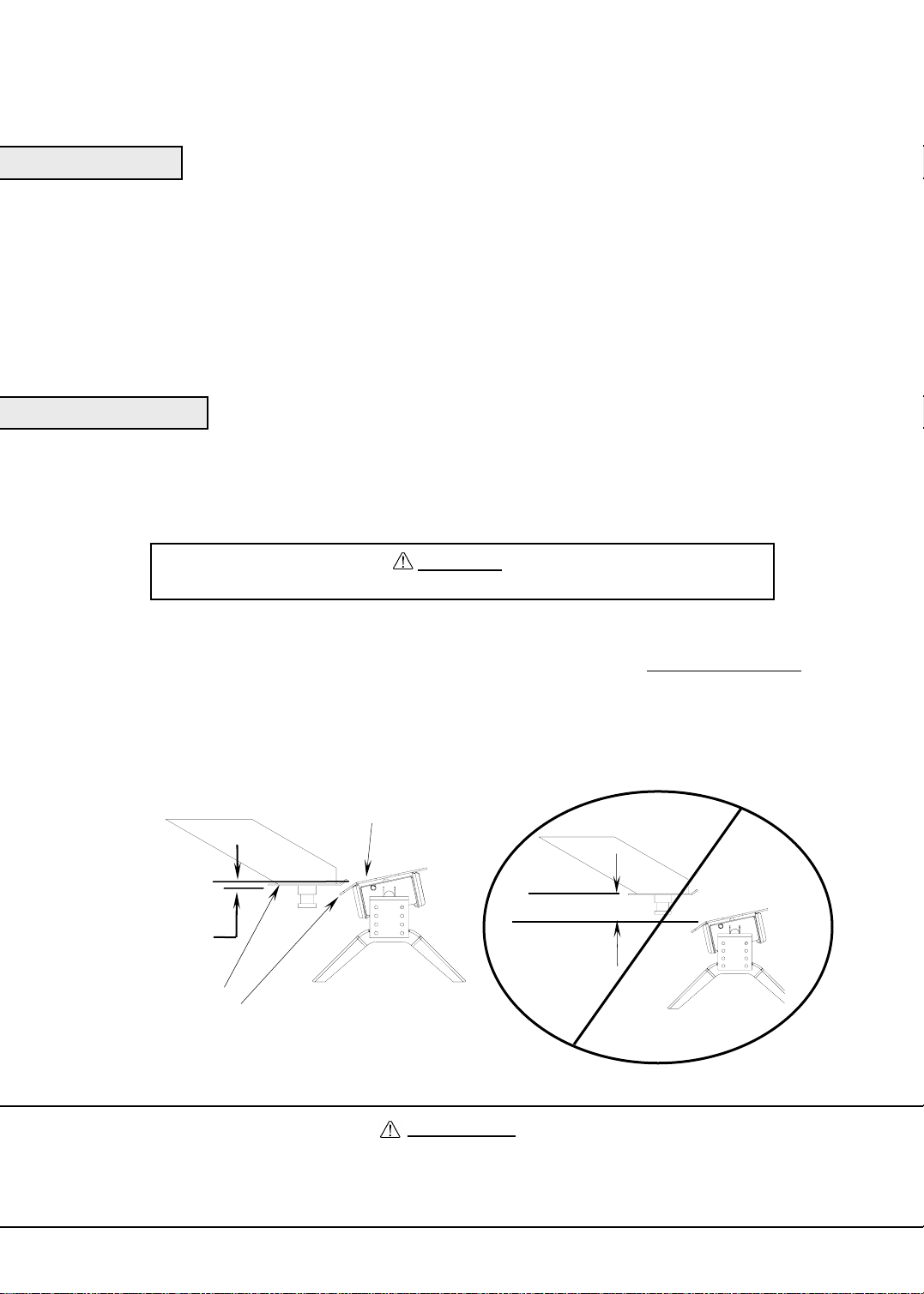
2. Using trailer jacks, adjust trailer height following the directions in the trailer manual so that bottom of trailer pin box (“A” in Fig. 6)
is ½ to 1 inch below skid plate (See “B” in Fig. 8). During the hitching maneuver, the bottom of the trailer in box should come in
contact with skid plate ramp (“C” in Fig. 8).
Hitch Skid Plate (B)
HAVE BEEN
Bottom of Pin Box (A)
1/2 To 1 Inch Below
Hitch Skid Plate (B)
Bottom of Pin Box (A)
Skid Plate Ramp (C)
Fig. 8
CORRECT
Bottom of Pin
Box Above
Hitch Skid Plate
Fig. 9
WRONG
WARNING:
Failure to follow this instruction may result in king pin being too high and coming to rest on top of closed
locking bar or not completely inside locking bar. (See Fig. 9). This could result in trailer separating from hitch.
Trailer separation may result in death or serious injury if anyone is under the trailer or between truck and
trailer when separation occurs.
30056IN – 21DEC05I PCN8397 ©2006 Cequent Towing Products Litho in USA 5
Page 6
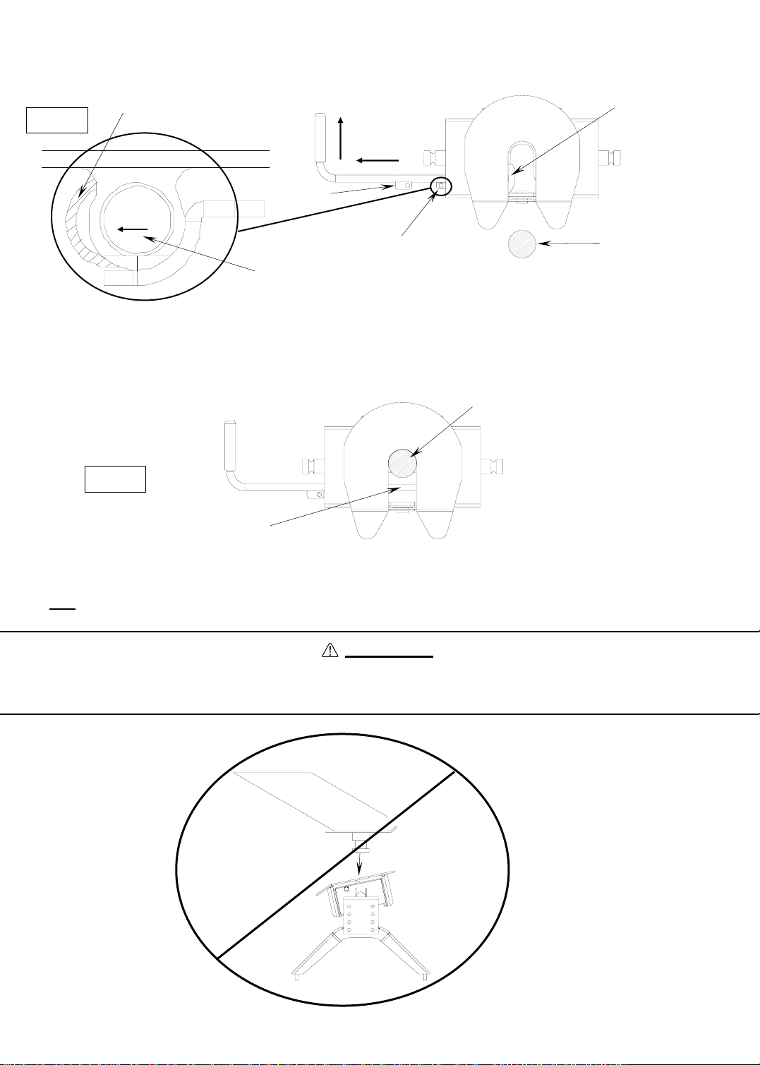
3. Pull handle out (A) and forward (B) so that the handle rests in the handle groove on the side of the hitch head and cocks it open.
(See Fig. 10). The hitch is now ready to accept the trailer king pin.
Fig. 10
Handle Groove
B
Locking Bar Retracted
A
Handle Tab
B
Sleeve
Handle
4. With locking bar in the open position (See Fig. 10), back truck slowly into trailer king pin until locking bar slides behind
king pin. The locking bar will automatically trap king pin when the king pin is inserted into the hitch far enough to disengage
locking bar (See Fig. 11).
King pin
Fig. 11
King pin
Locking Bar Closed
5. Use only
the method described above for hitching.
WARNING:
Do not attempt to hitch by using trailer jacks to lower trailer and king pin. This could result in king pin
coming to rest on top of skid plate instead of within hitch opening where locking bar is located. King pin
could slide off hitch and trailer could drop, re sulting in death or serious injury (See Fig. 12).
Fig. 12
WRONG
30056IN – 21DEC05I PCN8397 ©2006 Cequent Towing Products Litho in USA 6
Page 7
6. With:
•All trailer wheels still firmly blocked,and
•Landing gear still resting on firm ground and supporting trailer weight, and
•Truck stationary and in park with emergency brake on:
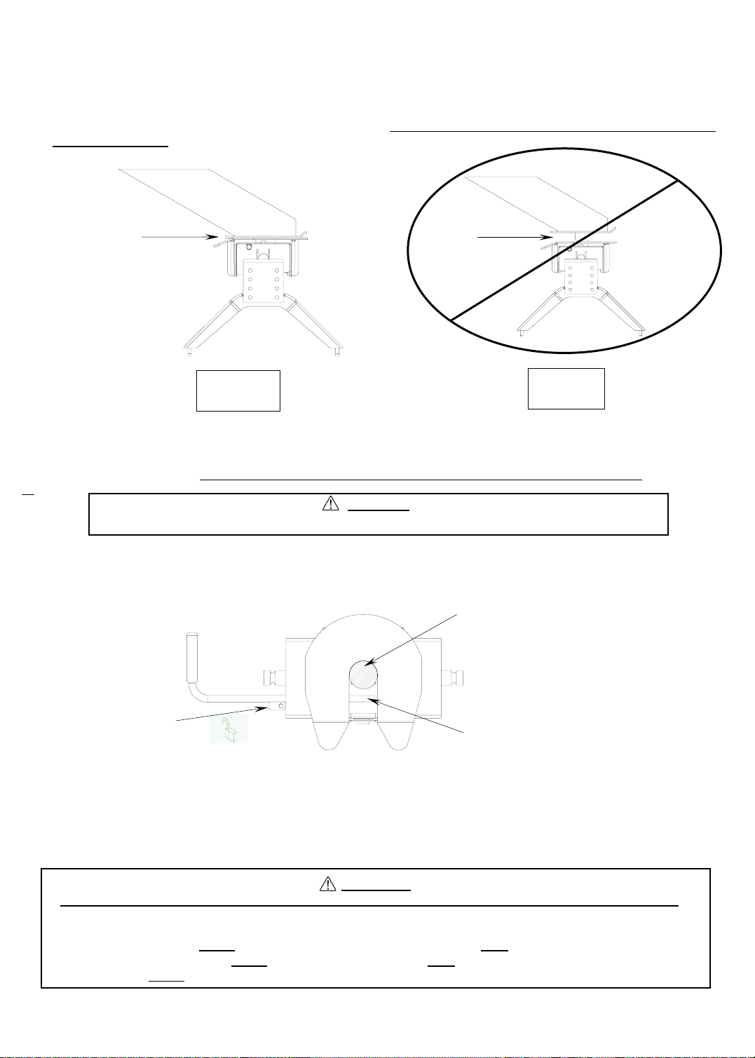
Visually check that bottom of pin box is resting on top of the hitch. THERE SHOULD BE NO SPACE BETWEEN
THESE SURFACES (See Fig. 13). If space exists, (See Fig. 14) trailer has not been properly hitched. DO NOT TOW!
Instead, repeat above steps until trailer is properly hitched. DO NOT PLACE BODY UNDER TRAILER TO PERFORM
THIS INSPECTION!
No Space
Fig. 13
CORRECT
7. The round hole in the handle tab on the tubular handle should now line up with the hole in the sleeve (Fig. 10) on the front
left corner of the hitch head (Fig. 11). Insert a lock through the holes in handle tab and sleeve. IF HOLES ARE NOT
ALIGNED, TRAILER HAS NOT BEEN PROPERLY CONNECTED TO HITCH. DO NOT TOW! Instead, repeat above steps
until trailer is properly hitched. DO NOT PLACE BODY UNDER TRAILER TO PERFORM THIS INSPECTION!
WARNING
Failure to use a pad lock could result in trailer suddenly becoming unhitched (see Fig. 15).
Do Not force handle should it not be aligned to permit locking. Check that the trailer plate is resting on the skid plate and
applying downward pressure. Lower trailer by raising trailer jacks if necessary and with the trailer wheels blocked on both
sides, move the truck slightly back and forth to allow the king pin to engage. Handle should be all the way in and lock should
be inserted through handle tab and sleeve.
Fig. 15
High Pin
Fig. 14
WRONG
King Pin
Handle Tab
Insert padlock in
aligned holes.
8. With:
•All trailer wheels still firmly blocked in front and behind each tire, and
•Truck stationary with the emergency brake on, and
•Trailer landing gear still resting on firm ground and supporting trailer weight:
Connect electrical cable between truck and trailer, connect breakaway switch cable from pin box to a permanent
part of truck, and raise tailgate of truck.
Locking Bar Closed
WARNING
●WHENEVER POSSIBLE, AVOID PUTTING BODY UNDER TRAILER OR BETWEEN TRUCK AND TRAILER
●If you need to place any part of your body under trailer or between truck and trailer:
●All trailer tires MUST
●Trailer landing gear MUST be resting on firm ground AND
●Truck MUST be stationary, in park, with emergency brake on!
30056IN – 21DEC05I PCN8397 ©2006 Cequent Towing Products Litho in USA 7
be blocked in front and behind each tire AND
Page 8
PULL TEST
WARNING:
Failure to perform this test may r esult in death or serious injury!
1. With:
•All trailer wheels still firmly blocked, and
•Trailer land gear still resting on firm ground and supporting trailer weight and,
•Truck stationary and with emergency brake on:
Return to cab of truck and release truck’s emergency brake. Apply trailer brakes. After making sure no one is between
truck and trailer, try to pull trailer slowly forward with the truck. If the trailer is properly hitched, the wheel blocks and trailer
brakes should keep the truck from moving forward.
NOTE: If trailer is not properly hitched, trailer will separate from hitch and truck will move forward leaving trailer behind. If
the trailer landing gear is still on resting on firm ground supporting trailer weight and wheels are blocked, trailer will
not be able to drop or fall
WARNING:
Failure to keep wheels blocked and landing gear down could result in trailer suddenly
moving or falling. This could result in death o r serious injury!
2. After successfully performing above steps, fully raise trailer landing gear (see trailer manual).
3. Check and inspect all electrical circuits for proper operation. (Clearance lights, turn signals, stop lights, etc.).
4. Remove and store all trailer wheel blocks.
UNHITCHING PROCEDURE:
PERFORM THE FOLLOWING IN THIS ORDER:
1. Place blocks firmly against front and rear of each trailer wheel to prevent any possible forward or rearward motion.
2. Using trailer jacks, lower trailer landing gear following the directions in the Trailer Manual until feet of landing gear are
resting on firm ground.
3. Make sure truck is in park with the emergency brake on.
WARNING:
Trailers that are not stable or properly hitched can fall and kill you! To avoid
death or serious injury:
• All trailer tires MUST
• Trailer landing gear MUST be resting on firm ground AND
• Truck MUST be stationary, in park, with emergency brake on!
4. Lower truck tail gate.
5. Disconnect power cable and breakaway switch cable between truck and trailer.
6. Remove lock from handle tab and sleeve.
7. Make sure that there is no rearward load on the king pin locking bar. If this is the case, the handle and king pin locking bar
will be difficult to open. DO NOT FORCE HANDLE. Back truck into trailer and reset truck emergency brakes.
8. Pull handle out (A) and forward (B) so that the groove in the handle catches the side of the hitch head and cocks it open
(C). See Figures 16 and 17.
be blocked in front and behind each tire AND
30056IN – 21DEC05I PCN8397 ©2006 Cequent Towing Products Litho in USA 8
Page 9

Handle Tab
Pull Handle all the
way out and
forward
B
A
Locking Bar
Fig. 16 Fig. 17
Handle Groove
B
Handle
9. AFTER MAKING CERTAIN NO ONE IS STANDING BETWEEN TRUCK AND TRAILER OR IN FRONT OF TRUCK,
drive truck slowly away from trailer.
WARNING
Whenever possible, avoid putting body under trailer or between truc k and trailer
If you need to place any part of our body under trailer or between truck and trailer:
•All trailer tires MUST
•Trailer landing gear MUST be resting on firm ground AND
•Truck MUST be stationary, in park, with emergency brake on!
10. Close locking bar by pulling handle out and back.
(Spring should close locking bar.)
11. KEEP WHEEL BLOCKS IN PLACE. This will keep trailer from moving unexpectedly.
12. Close tailgate if desired
MAINTENANCE:
1. Recheck tightness of all hardware every 1000 miles of use.
be blocked in front and behind each tire AND
2. See “Before each trip” section in this manual.
30056IN – 21DEC05I PCN8397 ©2006 Cequent Towing Products Litho in USA 9
Page 10

GENERAL INSTRUCTIONS FOR BASE RAIL INSTALLATION
TOOLS
3/16" drill 3/4" Socket & Open End Wrench
17/32" drill 100 lb-ft Torque Wrench
1” drill (Some Dodge application only) "C" Clamps
1. The following instructions should be used to mount the 5th wheel. Care and attention to detail will ensure a quick
quality installation. Check parts against parts list to become familiar with parts in kit. (See Fig. 19)
2. Raise rear of truck high enough to allow jack stands to be placed under rear spring hanger bracket of truck. This will
provide maximum room to install the 5th wheel brackets.
WARNING:
If the truck is raised, be sure that the truck is properly blocked and restrained to prevent
the truck from falling. Failure to do so may result in the truck suddenly falling, causing
death or serious injury.
3. Do not install mounting rails over plastic bed liners. Plastic bed liners must be cut out of the way. Base rails may be
installed on spray in liner. Note: Consult installer for recommended curing time.
4. Use only Cequent Towing Products supplied bolts, nuts, and washers to install this kit. All bolts are grade 5 and nuts
are grade 5 unless specified otherwise.
5. Specific instructions for most commonly used vehicles are included. If these instructions do not apply to your vehicle,
be sure that each end of each base rail is connected to the vehicle frame. Each frame bracket must be bolted to the
vehicle frame with two bolts, unless optional weld is used.
CAUTION:
These instructions are guidelines only. Actual installation is the responsibility of the
installer and the owner. Always measure truck and trailer before installing hitch to be
sure that there is cl earance at the cab and at the bumper to allow for turns.
To prevent the trailer from hitting the cab with the trailer turned 90°, the center of the hitch should be at least 52" from
the back of the cab when using a long bed truck. (Actual distance required will depend on trailer width and king pin
location.) Short bed (Minimum 38” from back cab to axle center line) trucks require a minimum of a 13” extended pin
box for regular maneuvers and do not apply.
6. Measurements are given from Rear Edge of truck bed to rear edge of the base rail closest to the Rear Edge of truck
for most vehicle applications (see Fig. 18).
7. Center hitch between fender wells and make sure rails are square. Adjust position of rails until both diagonal
measurements are the same. This should allow installation of a gooseneck or other 5th wheels to these rails (Refer to
Fig. 18 below).
8. Drill 8 holes identified in Fig. 18. (Hole location will vary for individual vehicle applications.) Drill all holes with 3/16"
drill and enlarge them with a 17/32" drill. Always use sharp drill bits. A 3/16" pilot hole will greatly speed drilling larger
holes. Install 1/2” carriage bolts into holes. Install 5/16” thick slotted spacer above or below bed to fill corrugations in
bed floor. NOTE: For Toyota Tundra application, part #58197 spacer kit is required. Stack (1) 3/ 16” and (1) 5/16”
thick slotted spacer to avoid crushing of truck bed.
CAUTION:
Check for obstructions before drilling. Failure to do so could result in damaged fuel or brake lines, structural
members, etc. Cequent Towing Products does its best to communicate tow vehicle manufacturer changes;
however, it is ultimately the responsibility of the install er to prevent damage due to instal lation.
9. Install mounting brackets onto carriage bolts with the long brackets on forward bolts and short brackets on rearward
(long and short brackets can be interchanged as needed). Secure bolts through mounting brackets with serrated
washers, lock washers, and hex nuts. Secure the other four bolts through the bed with flat washers, lock washers, and
nuts.
For Installation Assistance or Technical Help, Call 1-888-521-0510
30056IN – 21DEC05I PCN8397 ©2006 Cequent Towing Products Litho in USA 10
Page 11

10. Drill two holes in frame for each bracket. Select the holes which will give the greatest spread
between bolts. Install eight 1/2”-13x1-3/8” ribbed neck bolts, (threads pointing out), lock washers, and
hex nuts. Tighten nuts until bolt heads seat. Lubrication of knurls of all rib neck bolts is recommended.
Note: On vehicles with heavy duty suspensions, check for interference with bolts where brackets are
mounted to frame. If interference with suspension spring results, cut bolt flush to nut outboard of frame
or use weld option.
WARNING:
DO NOT lubricate threads. It may cause bolt failure.
CAUTION:
Check for obstructions before drilling. Failure to do so could result in damaged fuel or
brake lines, structural members, etc. Cequent Towing Products does its best to
communicate tow vehicle manufacturer changes; however, it is ultimately the
responsibility of the installer to pr event damage due to installation.
CAUTION:
It is important that 17/32" drill be used for holes in chassis frame as rib neck bolts
may break if too small a hole is used and neck may not grip if too large a hole is used.
11. Torque all nuts to 85 lb-ft
12. Pull wire provided to pull rib neck bolts through frame as needed per application
Drill locations will vary. See individual installation for location
Use side bracket/hitch base assembly to position rails (not included)
ROW 2
ROW 1
ROW 3
ROW 4
Rear Edge of
Truck Bed
Measure diagonal
from same
reference point.
Measurement
should be the
same.
Rear Edge of Truck bed to
Rear Edge of Base Rail
Front
of
Truck
Fig. 2
Choose 10 holes
identified by black dots
that correspond with
your individual
configuration. (‘00 and
newer, GM Silverado
Pattern Shown)
Each base rail must
have a bolt in either of
the marked center holes.
Check for obstructions
before drilling.
30056IN – 21DEC05I PCN8397 ©2006 Cequent Towing Products Litho in USA 11
Page 12

GM ‘99 Silverado, Sierra (not Sierra Classic) models
GM ‘00 and newer Silverado,Sierra models including HD models
CAUTION!
Read pages 2-3 of these instructions before starting installation. Failure to do so could result in significant vehicle damage!
IMPORTANT NOTES FOR THIS INSTALLATION:
1. Find parallel rows of bed sill spot welds in bed of truck. No drilling should be done in the ~4” between parallel rows of
spot welds where the bed sill sits.
Front of
Vehicle
Each base rail must have a
bolt in either of the marked
center holes. Check for
obstructions before drilling.
ROW 1
ROW 2
ROW 4
ROW 3
Rear Edge of
Truck Bed
30” Long Box
25 1/8” Short Box
Measure from rear edge of
truck bed to rear edge of
base rail
King pin centered over Axle
Side Bracket
Long Box Bed Sills
Short Box Bed Sills
Long bracket
Axle Center
Drivers side of 3/4 ton HD shown
Short bracket
* Optional weld
pattern
1/4 1.5-3
*
1/4 2
Note: Pull wire provided, may be needed
to install hardware in bracket thru frame.
CAUTION!
Check for obstructions before drilling. Failure to do so could result in damaged fuel or brake line s , structural members, etc.
Cequent Towing Products does its best to communicate tow vehicle manufacturer changes; however, it is ultimately the
responsibility of the installer to prevent damage due to installation.
30056IN – 21DEC05I PCN8397 ©2006 Cequent Towing Products Litho in USA 12
1/4 2
1/4 2
*
Page 13

CHEVROLET/GMC 88-98 / 92-98 4-DOOR / ‘99 SILVERADO
SIERRA CLASSIC (WITH TAPERED FRAME) (RED TURN SIGNALS)
CAUTION!
Read pages 2-3 of these instructions before starting installation. Failure to do so could result in significant vehicle damage!
IMPORTANT NOTES FOR THIS INSTALLATION:
1. Find parallel rows of bed sill spot welds in bed of truck. No drilling should be done in the ~4” between parallel rows of
spot welds where the bed sill sits.
ROW 4
ROW 1
ROW 2
ROW 3
Rear Edge of
Front of
Truck Bed
Vehicle
Each base rail must have a
bolt in either of the marked
center holes. Check for
obstructions before drilling.
King Pin Center approx.. 1 1/2”
forward of Axle Center
Side Bracket
Bed Sill
Long bracket
1/4 1.5-3
*
1/4 2
Axle Center
Drivers side 1/2 ton Long Box shown
30 15/16” Long Box
26 3/16” Short Box
Measure from Rear Edge
of truck bed to rear edge
of base rail.
Short bracket
* Optional weld
1/4 2
1/4 2
*
pattern
CAUTION!
Check for obstructions before drilling. Failure to do so could result in damaged fuel or brake line s , structural members, etc.
Cequent Towing Products does its best to communicate tow vehicle manufacturer changes; however, it is ultimately the
responsibility of the installer to prevent damage due to installation.
30056IN – 21DEC05I PCN8397 ©2006 Cequent Towing Products Litho in USA 13
Page 14

Chevrolet 73 to 87 / 73 to 92 4-door (GMC) (34” Straight, with Outside Shock
Absorbers)
CAUTION!
Read pages 2-3 of these instructions before starting installation. Failure to do so could result in significant vehicle damage!
Front
of
Vehicle
Each base rail must have a
bolt in either of the marked
center holes. Check for
obstructions before drilling.
ROW 1
ROW 2
Drill through
bed and truck
frame
ROW 4
ROW 3
Rear Edge of
Truck Bed
34 7/8” Long Box
And Short Box
Measure from Rear Edge of truck
bed to rear edge of base rail.
King Pin Center approx.. 3 1/2”
forward of Axle Center
Side Bracket
Long bracket
1/4 1.5-3
*
1/4 2
DO NOT Torque to 85lb-ft
(tighten but do not crush bed sill)
Install spacer with 1/2” hole between frame and
bed. (Cut provided tube spacer down to fix snug
between frame and bed.)
Axle Center
Bed Sill
Drivers side of 1/2 ton Chevy Long Box Shown
* Optional weld
pattern
CAUTION!
Check for obstructions before drilling. Failure to do so could result in damaged fuel or brake line s , structural members, etc.
Cequent Towing Products does its best to communicate tow vehicle manufacturer changes; however, it is ultimately the
responsibility of the installer to prevent damage due to installation.
30056IN – 21DEC05I PCN8397 ©2006 Cequent Towing Products Litho in USA 14
Page 15

Chevrolet 73 to 87 / 73 to 92 4-door (GMC) (34” Straight, with Inside Shock Absorbers)
CAUTION!
Read pages 2-3 of these instructions before starting installation. Failure to do so could result in significant vehicle damage!
Front
of
Vehicle
Each base rail must have a
bolt in either of the marked
center holes. Check for
obstructions before drilling.
ROW 1
ROW 2
ROW 4
ROW 3
Rear Edge of
Truck Bed
34 7/8” Long Box
and Short Box
Measure from Rear Edge of truck
bed to rear edge of base rail.
King Pin Center approx.. 3 1/2”
forward of Axle Center
Side Bracket
Long bracket
1/4 1.5-3
*
1/4 2
DO NOT Torque to 85lb-ft
(tighten but do not crush bed sill)
Axle Center
Bed Sill
Drivers side of 1/2 ton Chevy Shown
Short bracket
* Optional weld
1/4 2
1/4 2
*
pattern
CAUTION!
Check for obstructions before drilling. Failure to do so could result in damaged fuel or brake line s , structural members, etc.
Cequent Towing Products does its best to communicate tow vehicle manufacturer changes; however, it is ultimately the
responsibility of the installer to prevent damage due to installation.
30056IN – 21DEC05I PCN8397 ©2006 Cequent Towing Products Litho in USA 15
Page 16

Ford ‘97 to ’03 F-150 & F-250 8500 GVW AND UNDER and ’04 Heritage Series Body Style
Note: ’04 AND NEWER F-150 requires Bracket Kit 58241 (Sold Separately)
CAUTION!
Read pages 2-3 of these instructions before starting installation. Failure to do so could result in significant vehicle damage!
IMPORTANT NOTES FOR THIS INSTALLATION:
1. Long and Short Brackets on Driver’s Side may need to be switched to avoid interference with exhaust hanger.
2. May need to move base rail location +/- 1/2” to ensure frame brackets do not interfere with bed sills.
Front
of
Vehicle
Each base rail must have a
bolt in either of the marked
center holes. Check for
obstructions before drilling.
ROW 1
ROW 2
ROW 3
ROW 4
Rear Edge of
Truck Bed
29 1/4” Long Box
and Short Box
Measure from Rear Edge
of truck bed to rear edge
of base rail.
King Pin Center approx.. 1 1/2”
forward of axle center.
Side Bracket
May need to move slightly to
avoid interference with fuel lines
Long bracket
Axle Center
Bed Sill
Drivers side of F150 shown
Short bracket
* Optional weld
1/4 1.5-3
*
1/4 2
1/4 2
1/4 2
CAUTION!
Check for obstructions before drilling. Failure to do so could result in damaged fuel or brake line s , structural members, etc.
Cequent Towing Products does its best to communicate tow vehicle manufacturer changes; however, it is ultimately the
responsibility of the installer to prevent damage due to installation.
30056IN – 21DEC05I PCN8397 ©2006 Cequent Towing Products Litho in USA 16
pattern
*
Page 17

FORD F-150 & F-250 THROUGH ’96 / ‘97 F-250 OVER 8500 GVW, F350 THROUGH ’97 /
1999 & NEWER F-250 & F-350 SUPERDUTY
CAUTION!
Read pages 2-3 of these instructions before starting installation. Failure to do so could result in significant vehicle damage!
IMPORTANT NOTES FOR THIS INSTALLATION:
1. On short bed vehicles, attach Driver’s Side forward bracket on Row 2 to avoid interference with fuel lines.
2. On vehicles with overload springs, switch position of long and short brackets.
3. May need to move base rail location +/- 1/2” to ensure frame brackets do not interfere with bed sills.
Front
of
Vehicle
Each base rail must have a
bolt in either of the marked
center holes. Check for
obstructions before drilling.
ROW 1
ROW 2
ROW 4
ROW 3
Rear Edge of
Truck Bed
32 1/2” Long Box
and Short Box
Measure from Rear Edge of truck
bed to rear edge of base rail.
Axle CenterKing Pin Center approx.. 4” forward of Axle Center
Side Bracket
Long bracket Short bracket
1/4 1.5-3
*
1/4 2
Bed Sill
1/4 2
1/4 2
Drivers side of F350 Super
Duty long box Shown
* Optional weld
pattern
*
CAUTION!
Check for obstructions before drilling. Failure to do so could result in damaged fuel or brake line s , structural members, etc.
Cequent Towing Products does its best to communicate tow vehicle manufacturer changes; however, it is ultimately the
responsibility of the installer to prevent damage due to installation.
30056IN – 21DEC05I PCN8397 ©2006 Cequent Towing Products Litho in USA 17
Page 18

DODGE ‘02 AND NEWER 1500 / ‘03 AND NEWER 2500 WITHOUT OVERLOAD
BRACKETS (‘03 2500 WITH OVERLOAD AND 3500 REQUIRE BRACKET KIT 58186)
CAUTION!
Read pages 2-3 of these instructions before starting installation. Failure to do so could result in significant vehicle damage!
IMPORTANT NOTES FOR THIS INSTALLATION:
1. Tube spacer and 4 1/2” carriage bolt used to attach through rearward Bed Sill (Row 3).
2. **Rib neck bolts will need to be pulled through access holes in frame with supplied pull wire (see below).
3. Do not drill thru both walls
of frame. Drill only thru wall
of frame to which bracket is
mounted.
4. It is very important that
brackets in Row 2 are against
rear side of Bed Sill as shown.
Due to dimensional instability in
Bed Sill placement with the
Dodge truck, interference could
result when drilling in Row 3.
Observe caution note below and
double check all areas prior to
drilling.
5. To avoid drilling inside of
frame, (Passenger Side
Row 3) Optional Custom
Bracket (58023) can be
purchased from your
dealer. The use of this
bracket allows for drilling
outside the frame and
avoids exhaust hanger.
6. *Due to tubular frames
having thinner walls than
previous C channel
frames, extra caution
needs to be used when
mounting with the optional
welding.
Front
Vehicle
of
ROW 1
ROW 2
Drill through
Bed Sill with
17/32” drill.
Open up hole
through truck
bed only with
1” dia. drill.
Drop tube
spacer through
hole in truck
bed to avoid
crushing Bed
Sill when
torquing 4 1/2”
carriage bolt.
ROW 3
ROW 4
Each base rail must have a
bolt in either of the marked
center holes. Check for
obstructions before drilling.
Rear Edge of
Truck Bed
28 5/16” Long Box
26 5/16” Short Box
Measure from Rear
Edge of truck bed to
rear edge of base rail.
King Pin Centered
over Axle Center
Use provided tube spacer and 4 1/2”
carriage bolt to attach through Bed
Sill
Drivers side of 1500 Ram Long box Shown
Short bracket (driver’s side) outside frame
1/4 2
1/4 2
**Rearward access hole (in bottom of frame)
* Optional weld
*
pattern
Bed Sill
Long bracket
1/4 1.5-3
*
1/4 2
Side Bracket
Short bracket (passenger
side), inside frame.
CAUTION!
Check for obstructions before drilling. Failure to do so could result in damaged fuel or brake line s , structural members, etc.
Cequent Towing Products does its best to communicate tow vehicle manufacturer changes; however, it is ultimately the
responsibility of the installer to prevent damage due to installation.
30056IN – 21DEC05I PCN8397 ©2006 Cequent Towing Products Litho in USA 18
Page 19

DODGE ‘03 AND NEWER 2500 AND 3500 (REQUIRES 58186 BRACKET KIT )
CAUTION!
Read pages 2-3 of 30035 instructions before starting installation. Failure to do so could result in significant vehicle damage!
IMPORTANT NOTES FOR THIS INSTALLATION:
1. Tube spacers and 4 1/2” carriage bolts used to attach through rearward Bed Sill (Row 3).
2. **Rib neck bolts will need to be pulled through rearward access holes in frame with supplied pull wire (see below).
3. Do not drill thru both walls of
frame. Drill only thru wall of
frame to which bracket is
mounted.
4. It is very important that
brackets in Row 2 are against
rear side of Bed Sill as shown.
Due to dimensional instability
in Bed Sill placement with the
Dodge truck, interference
could result when drilling in
Row 3. Observe caution note
below and double check all
areas prior to drilling.
5. Rear brackets can be
mounted to frame with (2)
bolts in any combination
of the three bracket holes.
6. *Due to tubular frames
having thinner walls than
previous C channel frames,
extra caution needs to be
used when mounting with the
optional welding.
Front
of
Vehicle
ROW 1
ROW 2
Drill through
Bed Sill with
17/32” drill.
Open up hole
through truck
bed only with
1” dia. drill.
Drop tube
spacer
through hole
in truck bed to
avoid crushing
Bed Sill when
torquing 4 1/2”
carriage bolt.
ROW 3
ROW 4
Drill 2 center holes shown in
addition to 8 holes for 30035
kit. Install 1/2” carriage bolts,
slotted spacer above or below
bed to fill bed corrugation, and
bolt plate below bed with
washer and nut.
Rear Edge of
Truck Bed
28 5/16” Long Box
26 5/16” Short Box
Measure from Rear
Edge of truck bed to
rear edge of base rail.
King Pin Centered
Bed Sill
Long bracket
1/4 1.5-3
*
1/4 2
over Axle Center
Side Bracket
**Rearward access hole
(in top of frame)
Use provided(30035 kit) tube
spacers and 4 1/2” carriage bolts
to attach through Bed Sill
Drivers side of 2500 Ram Long box Shown
Inside frame
1/4 2
1/4 2
*
* Optional weld
pattern
CAUTION!
Check for obstructions before drilling. Failure to do so could result in damaged fuel or brake line s , structural members, etc.
Cequent Towing Products does its best to communicate tow vehicle manufacturer changes; however, it is ultimately the
responsibility of the installer to prevent damage due to installation.
30056IN – 21DEC05I PCN8397 ©2006 Cequent Towing Products Litho in USA 19
Page 20

DODGE ‘94 to ‘01 1500 / ‘94 to ‘02 2500/3500 (FULL SIZE, SHORT AND LONG BOX)
CAUTION!
Read pages 2-3 of these instructions before starting installation. Failure to do so could result in significant vehicle damage!
IMPORTANT NOTES FOR THIS INSTALLATION:
1. It is very important that brackets in Row 2 are against forward side of bed sill as shown below. Due to
dimensional instability in bed sill placement with the Dodge truck, interference could result when drilling in Rows 3
or 4. May need to move base rail location +/- 1/2” to ensure frame brackets do not interfere with bed sills.
Front
of
Vehicle
Each base rail must have a
bolt in either of the marked
center holes. Check for
obstructions before drilling.
ROW 1
ROW 2
ROW 3
ROW 4
Rear Edge of
Truck Bed
32 7/16” Long Box
28 7/16” Short Box
Measure from Rear Edge of truck
bed to rear edge of base rail.
King Pin Center approx. 2”
forward of Axle Center
Side Bracket
Long bracket
Axle Center
Bed Sill
Drivers side Ram 1500 Shown
Short bracket
* Optional weld
pattern
1/4 1.5-3
*
1/4 2
1/4 2
1/4 2
*
CAUTION!
Check for obstructions before drilling. Failure to do so could result in damaged fuel or brake line s , structural members, etc.
Cequent Towing Products does its best to communicate tow vehicle manufacturer changes; however, it is ultimately the
responsibility of the installer to prevent damage due to installation.
30056IN – 21DEC05I PCN8397 ©2006 Cequent Towing Products Litho in USA 20
Page 21

DODGE THROUGH 93 (FULL SIZE)
CAUTION!
Read pages 2-3 of these instructions before starting installation. Failure to do so could result in significant vehicle damage!
IMPORTANT NOTES FOR THIS INSTALLATION:
1. May need to move base rail location +/- 1/2” to ensure frame brackets do not interfere with bed sills.
ROW 3
ROW 1
ROW 2
ROW 4
Rear Edge of
Truck Bed
Front
of
Vehicle
Each base rail must have a
bolt in either of the marked
center holes. Check for
obstructions before drilling.
King Pin Centered over Axle
Side Bracket
Long bracket
1/4 1.5-3
*
1/4 2
Axle Center
Bed Sill
29 5/8” Long Box
and Short Box
Measure from Rear Edge of truck
bed to rear edge of base rail.
Drivers side of 1/2 ton Ram Shown
Short bracket
* Optional weld
1/4 2
1/4 2
pattern
*
CAUTION!
Check for obstructions before drilling. Failure to do so could result in damaged fuel or brake line s , structural members, etc.
Cequent Towing Products does its best to communicate tow vehicle manufacturer changes; however, it is ultimately the
responsibility of the installer to prevent damage due to installation.
30056IN – 21DEC05I PCN8397 ©2006 Cequent Towing Products Litho in USA 21
Page 22

DODGE ’94 to 2004 DAKOTA
CAUTION!
Read pages 2-3 of these instructions before starting installation. Failure to do so could result in significant vehicle damage!
IMPORTANT NOTES FOR THIS INSTALLATION:
1. Find parallel rows of bed sill spot welds in bed of truck. No drilling should be done in the ~4” between parallel
rows of spot welds where the bed sill sits.
2. Cut 1” from top flange of brackets. Under bed, mount brackets with flanges facing out.
3. Put rear brackets on Row 3 for ‘97 to Present models. Put brackets on Row 4 for ‘96 and Earlier models.
1"
Cut Off
Frame Bracket
Front
of
Vehicle
Each base rail must have a
bolt in either of the marked
center holes. Check for
obstructions before drilling.
ROW 1
ROW 2
ROW 3
ROW 4
Rear Edge of
Truck Bed
26” Long Box
and Short Box
Measure from Rear
Edge of truck bed to
rear edge of base rail.
King Pin Centered over Axle
Side Bracket
Long bracket
1/4 1.5-3
*
1/4 2
1997 to 2004
Axle Center
Bed Sill
Up to & Including 1996
Drivers side Dakota Shown
Short brackets
* Optional weld
1/4 2
1/4 2
*
pattern
CAUTION!
Check for obstructions before drilling. Failure to do so could result in damaged fuel or brake line s , structural members, etc.
Cequent Towing Products does its best to communicate tow vehicle manufacturer changes; however, it is ultimately the
responsibility of the installer to prevent damage due to installation.
30056IN – 21DEC05I PCN8397 ©2006 Cequent Towing Products Litho in USA 22
Page 23

TOYOTA TUNDRA 2000 & NEWER (STANDARD CAB LONG BOX ONLY)
CAUTION!
Read pages 2-3 of these instructions before starting installation. Failure to do so could result in significant vehicle damage!
NOTE: For Toyota Tundra application, part #58197 spacer kit is required. Stack (1) 3/16” and (1) 5/16” thick
slotted spacer to avoid crushing of truck bed.
Front
of
Vehicle
Each base rail must have a
bolt in either of the marked
center holes. Check for
obstructions before drilling.
ROW 1
ROW 2
ROW 3
ROW 4
Rear Edge of
Truck Bed
32 1/2” Long Box (Only)
Measure from Rear Edge of truck
bed to rear edge of base rail.
King Pin Centered approx.. 1 1/4”
forward of Axle Center
Side Bracket
Long bracket
1/4 1.5-3
*
1/4 2
Axle Center
1/4 2
1/4 2
Drivers side shown
*
Short bracket
* Optional weld
pattern
CAUTION!
Check for obstructions before drilling. Failure to do so could result in damaged fuel or brake line s , structural members, etc.
Cequent Towing Products does its best to communicate tow vehicle manufacturer changes; however, it is ultimately the
responsibility of the installer to prevent damage due to installation.
30056IN – 21DEC05I PCN8397 ©2006 Cequent Towing Products Litho in USA 23
Page 24

NOTES
THREE YEAR LIMITED WARRANTY
Cequent Towing Products warrants its 5th Wheels from date of purchase against defects in material and workmanship under normal use and
service, ordinary wear and tear excepted, for 3 years of ownership to the original consumer purchaser when a Cequent Towing Products
mounting kit is used.
Products used by professional hauler’s are subject to Towing Product’s limited One (1) year warranty.
Cequent Towing Products will replace FREE OF CHARGE any part which proves defective in material or workmanship when presented to any
Cequent Towing Products dealer (consult local telephone directory) or Cequent Towing Products warehouse, or when returned to the factory,
TRANSPORTATION CHARGES PREPAID, at the address below. THIS WARRANTY IS LIMITED TO DEFECTIVE PARTS REPLACEMENT
ONLY. LABOR CHARGES AND/OR DAMAGE INCURRED IN INSTALLATION OR REPLACEMENT AS WELL AS INCIDENTAL AND
CONSEQUENTIAL DAMAGES CONNECTED THEREWITH ARE EXCLUDED.
Some states do not allow the exclusion or limitation of incidental or consequential damages, so the above limitation or exclusion may not apply
to you.
Any damage to the 5th Wheel as a result of misuse, abuse, neglect, accident, improper installation, or any use violative of the instruction
furnished by us WILL VOID THE WARRANTY.
This warranty gives you specific legal rights, and you may also have other rights which vary from state to state. In the event of a problem with
warranty service or performance, you may be able to go to a small claims court, a state court, or a federal district court.
Cequent Towing
Products 47774 Anchor
Court West Plymouth,
30056IN – 21DEC05I PCN8397 ©2006 Cequent Towing Products Litho in USA 24
MI 48170
Page 25

35
36
Fig. 19
34
18
37
14
15
25
5
17
13
27
29
28
26
23
31
12
11
3
10
9
7
8
15K 5TH WHEEL PCS.
11. LONG PULL PIN (4)
12. SPRING COTTER PIN (6)
13. LOCKING BAR (1)
17. SOLID INNER HANDLE (1)
18. HANDLE TAB (1)
23. SHORT PULL PIN (2)
26. 5TH WHEEL HEAD (1)
27. HEAD SUPPORT (1)
28. SIDE BRACKETS (2)
29.1/2”X4 1/2” BOLTS (4)
31. 1/2” LOCK NUTS (4)
34. DRIVE PIN (1)
35. HANDLE, TUBE (1)
36. HANDLE GRIP (1)
37. PAD LOCK (1)
14
15
1
6
4
2
BASERAILS PCS.
1. LONG BRACKET (2)
2. SHORT BRACKET (2)
3. FILLER SPACER (10)
4. SPACER (2)
5. CARRIAGE BOLTS (10)
6. KNURLED BOLTS (8)
7. 1/2” NUTS (18)
8. 1/2” LOCKWASHERS (18)
9. 1/2” SERRATED WASHERS (6)
10. 1/2” FLAT WASHERS (4)
14. 4” CARRIAGE BOLT (2)
15. TUBE SPACER (2)
25. BASERAILS (2)
30056IN – 21DEC05I PCN8397 ©2006 Cequent Towing Products Litho in USA 25
 Loading...