


RO-pro Reverse Osmosis System Manual
PROSEP FILTER SYSTEMS LTD
RO-pro SYSTEM
OPERATION & INSTALLATION INSTRUCTIONS
PROSEP FILTER SYSTEMS LTD
UNIT G19 RIVER BANK WAY, LOWFIELDS BUSINESS PARK, ELLAND, WEST YORKSHIRE, HX5 9DN
Tel: 01422 377367 Fax: 01422 377369
Email: domestic@prosep.co.uk Web: www.prosep.co.uk
Model Shown: RO-pro-625U
RO-pro-325
3 Stage Reverse Osmosis System
Lit/Dom/Instr/RO-Pro-325I&O/LE

RO-pro Reverse Osmosis System Manual
CONTENTS:
PAGE DESCRIPTION
3 Checklist
3 Recommended Tools List
4 Product Specifications
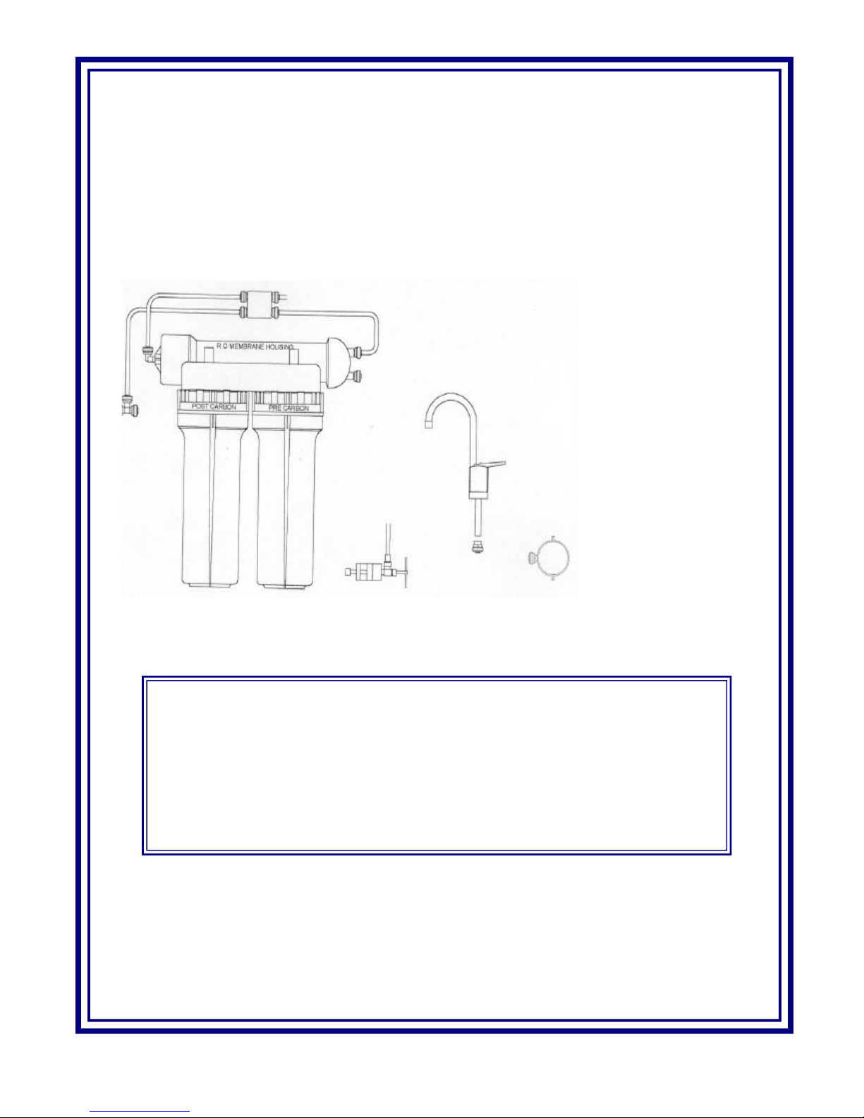
4 Installation Diagram
4 Replacement Parts
5 Fitting the Tap
5 Fitting the Saddle Tapping Valve
5 Fitting the Tank Ball Valve
5 Mounting the Drain Clamp
6 System Start Up
7 Filter Maintenance and Cartridge Change Instructions
8 Trouble Shooting
T
hank you for choosing your RO-pro Reverse Osmosis Drinking Water System from PROSEP Filter
Systems Ltd With proper care your water filtration system will produce high quality drinking water for
many years.
Read carefully and follow the instructions in this manual before proceeding with the actual installation. Pay
particular attention to all warnings, cautions and notes. Failure to do so could result in personal injury or
damage to equipment or other property. System and installation need to comply with local laws and regulations.
If you have any questions, please contact us.
PLEASE NOTE:PROSEP Filter Systems Ltd reserve the right to alter the specifications of this product without prior notice
RO-pro Reverse Osmosis System Manual
CHECK LIST:
1) TGI Reverse Osmosis System.
2) Water Storage tank, (2.8 gallon @ 40psi).
3) Four coloured tubing (black, blue, red, yellow) 1/4” OD (some supplied 3/8” OD), 4’ each colour.
4) Installation kit: tank ball valve, drain saddle tap valve, feed water valve, tap assembly.
5) Manual.
This Reverse Osmosis system contains a replaceable treatment component critical for effective reduction of total
dissolved solids.
System Tested and Certified by NSF International against ANSI/NSF Standard 58 for the reduction of Barium,
Cadmium, Copper, Cyst, Hexavalent Chromium, Lead, Radium 226/228, Selenium, TDS, Trivalent Chromium.
RECOMMENDED TOOLS LIST
† Variable speed drill
† 1/8” and 1/4” drill bits
† 7/16” drill bit 1/2” and 9/16 open-end wrenches (or adjustable)
† Phillips screwdriver
† Utility knife
† Teflon Tape
PRE PLUMBED REVERSE
OSMOSIS SYSTEM
SADDLE TAPPING VALVE
WITH TUBE ATTACHED
WATER STORAGE TANK AND
BALL VALVE
TAP AND
CONNECTOR
WASTE PIPE
CONNECTOR

RO-pro Reverse Osmosis System Manual
RO-pro-325 FILTRATION PROCESS
SPECIFICATIONS:
1st Stage: Carbon Block Pre-Filter Cartridge
2nd Stage: TFC Membrane 25 GPD
3rd Stage: Granular Activated Carbon Post-Filter Cartridge
Auto shut off valve
Operating Pressure: 40-120 PSI
Operating Temperature: 40 - 110 deg. F
Recovery Rate: 20-25%
Product Code Description Service Life
PRODOM0104 10 micron, 10" CTO Carbon Block Cartridge 6 months
PRODOM0161 25 GPD TFC Membrane 24 - 36 months
PRODOM0100 20 micron, 10" GAC Cartridge 6 months
REPLACEMENT PARTS:

RO-pro Reverse Osmosis System Manual
Chrome Tap
Counter Top
Black Rubber Washer
Black Locating Washer
Brass Nut
Stud
Pushfit
Connector
Blue Tubing
Locking Washer
FITTING INSTRUCTIONS:
Fitting The Pre-Plumbed RO System
Use the bracket as a template to mark the position of the unit on a suitable wall or cupboard panel. Allow a minimum
of 40mm clearance below the filter bowls to allow for filter change out. Drill and plug two holes and screw in 2
screws (not supplied) allowing the screw heads to protrude from the wall by approx.
5mm. Place the bracket over the screws and slide to left or right (as preferred) to lock
bracket in position.
Fitting The Tap
Select a suitable position on the work top or corner of the sink. Before drilling the
hole, check there is nothing directly underneath that could be damaged i.e.
water or waste pipes, cables etc. Also make sure that there is room for the
locating washer and that you can physically reach the tap stud to connect the
brass nut. Use a centre punch to mark the location of the hole to be drilled. Drill
a 3mm pilot hole. Enlarge the hole to 11mm. If you are drilling through
stainless steel, deburr and rough edges around the hole. Wipe clean with a soft
cloth. Check that the tap stud fits easily through the hole. Secure the push fit
connector and firmly push one end of the blue pipe into the collar within the
push-fit connector. Push the other end of the blue tubing into the push fit
connector fitted to the post carbon filter housing.Note: Some taps are supplied
with the blue tubing already permanently fitted. The tap has two ‘ON’
positions. Lift the lever up for continuous flow. Press the lever down for flow
that ceases when the lever is released.
Fitting The Saddle Tapping Valve
Although not essential, we recommend that you turn off the cold water stopcock
and relieve the water pressure by opening cold water tap. If the stopcock is under
the sink, fit the valve after the stopcock. The valve must be fitted on the cold
water supply only, (if you are uncertain, run the hot tap for a minute and feel the
pipes under the sink to distinguish the cold pipe).
Do not fit the valve on a bend, a join or where there is solder on the copper pipe.
Attach the clamp around the pipe and tighten the clamp bolt to ensure a water
tight seal. Do not over tighten the clamp bolt as this may distort the water pipe.
Firmly push the open end of the red tubing attached to the saddle tapping valve
into the collar on the front of the pre carbon filter housing.
Note: Later designs have the red tubing already permanently fitted to the valve.
The saddle tapping valve supplied with the RO-Pro System is designed to comply
with British plumbing codes. (See ‘System Start Up’ Section for further details
regarding the saddle tapping valve.) Note: Later designs have the red tubing already permanently fitted to the
valve. The saddle tapping valve supplied with the RO-Pro System is designed to comply with British plumbing codes.
Fitting The Tank Ball Valve
Remove the plastic cap on the top of the tank. Wrap the thread 3 or 4 times with plumbers tape (Teflon). Connect
the ball valve to the thread and make sure it is tight but not over-tight. Connect the yellow tubing to the tank ball
valve. Turn the tank ball valve off. Note: Do not tamper with the air valve on the low side of the storage tank. It has
been preset at 8-10 psi by the manufacturers.
Mounting The Drain Clamp
Position the drain saddle in the desired location (please see notes below), mark spot through thread outlet, remove
saddle. Drill 1/4” (6.3mm) hole into the drain pipe above the water line of the trap/U-bend. Fix self adhesive foam
seal over the hole in the drain saddle ensuring that the holes line up. Align the hole drilled in the drain pipe with the
drain saddle using a drill bit. Make sure to align drain saddle to drilled hole. Attach drain saddle to drain pipe and
tighten the two screws evenly. Connect the black tubing to the drain clamp.
Note: The drain clamp will fit most standard drain pipe 1 1/2” diameter. It should be installed above the trap/u-bend
and on the vertical or horizontal tailpiece. If a waste disposal unit is fitted, the drain clamp must not be fitted into the
same waste pipe.

RO-pro Reverse Osmosis System Manual
SYSTEM START UP:
Turn on the cold water supply at the stopcock and turn the cross piece on the saddle tap valve anti-clockwise
to open. Close the tank ball valve. Open the tap for continuous flow (Lever Up). Check the system for leaks,
tighten as necessary. After 10-30 minutes, water will start to drip out of the tap. Let it drip for about 10
minutes and then flip the tap handle to the closed position. TURN ON THE TANK BALL VALVE NOW.
It may now take several hours for the storage tank to fill, depending on the local water pressure.
Note: DO NOT DRINK THE WATER FROM THE FIRST TANK PRODUCED BY YOUR NEWLY PURCHASED RO-PRO
SYSTEM.
After the tank is full (you will hear the water stop), flush the system by placing the tap in the open position
until all the water is completely discharged. Upon complete discharge of the storage tank, return the tap
handle to the closed position and let the refilling process begin. This process could take 2-3 hours to
complete. After the second tank is filled, you may enjoy the pure water. Check for leaks daily for the first
week and periodically thereafter. You may notice that the water may be milky coloured during the first
week. This is caused by air bubbles in the water released from the carbon filter, they will dissipate on
allowing to stand. It is normal and safe.
NOTE:
DO NOT USE WITH WATER THAT IS MICRO BIOLOGICALLY UNSAFE OR OF UNKNOWN QUALITY WITHOUT
ADEQUATE DISINFECTION BEFORE OR AFTER THE SYSTEM. SYSTEMS CERTIFIED FOR CYST REDUCTION MAY
BE USED ON DISINFECTED WATER THAT MAY CONTAIN FILTERABLE CYSTS.
THIS REVERSE OSMOSIS SYSTEM CONTAINS A REPLACEABLE COMPONENT CRITICAL TO THE EFFICIENCY OF
THE SYSTEM. REPLACEMENT OF THE REVERSE OSMOSIS COMPONENT SHOULD BE WITH ONE OF IDENTICAL
SPECIFICATIONS, AS DEFINED BY THE MANUFACTURER, TO ASSURE THE SAME EFFICIENCY AND
CONTAMINANT REDUCTION PERFORMANCE.
WARNING: DO NOT USE THIS RO-PRO SYSTEM TO PURIFY NON-DRINKABLE SOURCES OF WATER THAT
ARE UNSAFE OR WITH WATER OF UNKNOWN QUALITY/
WARNING: NEVER USE HOT WATER OR ALLOW THE UNIT TO FREEZE.
WARNING: INCORRECT INSTALLATION WILL VOID THE WARRANTY.

RO-pro Reverse Osmosis System Manual
FILTER MAINTENANCE AND CHANGE INSTRUCTIONS:
This recommendation is intended for maximum efficiency of RO water production by your system.
1, Filter Maintenance
a, It is OK to put pre & post filters of the shelf for several years.
b, Keep the sealed, non-opened filter in an air tight container to prevent it from absorbing contaminants
from the air.
2, Membrane Maintenance
a, The dry packed membrane usually has a two-year shelf life. To prolong the shelf life, we recommend
you keep the non-opened dry membrane in the refrigerator.
b, Once used, we recommend you run the RO system every day, at least 10-15 minutes (about 1 gallon or 4
litres drinking water.) This helps to maintain the membrane performance.
c, If the RO system is not used for a few weeks, drain the storage tank. To bring the unit into service fill the
tank and drain it twice, to allow to refill. Your RO system will then be ready to reuse.
3, Filter & Membrane Change Procedures:
a, Shut off the water supply.
b, Turn off the tank ball valve by turning the handle through 90 degrees.
c, Open the tap fully for continuous flow.
d, Slide the housing wrench in (bowl spanner) over the filter bowl. Use one hand to hold the system and
the other hand to turn the wrench clockwise to separate the head from the bolw.
NOTE: IF IT IS TOO TIGHT TO OPEN THE HOUSING YOU MAY TRY TO UNPLUG THE FITTING
BETWEEN THE RED TUBING AND THE SYSTEMS IN ORDER TO REDUCE THE AIR AND WATER
PRESSURE INSIDE THE HOUSING.
e, After opening the housing, remove the used filter and put the new filter into the housing. The Carbon
Prefilter can be installed either way up. The blue GAC post filter must be installed the correct way up
with the white tapered cap to the top. Make sure the O-ring is in place and smear a little petroleum jelly
on the O-ring. Replace the filter bowl and tighten bu turning the bowl anti-clockwise.
f, Repeat previous step for all other filter changes. (See separate instructions for membrane change below.)
g, Turn on the water supply and make sure there are no leaks.
h, Let the water drip from the tap for about 10 minutes. If the water flow is less than 1 cup (8 oz or 240 ml)
per minute, it may be a signal to change the membrane.
i, Membrane Change Procedure:
Shut off water supply.
Unscrew the cap of the membrane housing.
Slide out the used membrane and discard. (You may need thin nosed pliers to grip the membrane spigot.)
Insert the new membrane with the 2 O-rings into housing first with the black brine seal at the open end
of the membrane housing.
Be sure it is fully seated into bottom end.
Screw cap back on to the membrane housing, make sure O-ring is still in place.
Turn on water supply & check for leaks.
It may take 10-20 minutes for new membrane to run to normal flow.
Carry out system start up procedure.

RO-pro Reverse Osmosis System Manual
TROUBLE SHOOTING
Note: Turn off the system before servicing
PROBLEM CAUSE SOLUTIONS
Milky coloured water Air in system
Air in the system is a normal occurrence with
initial startup of the RO System. This milky
look will disappear during normal use within
1 to 2 weeks.
Noise from tap
*Location of drain saddle
*Restriction in drain line
*Relocate the drain to above water trap
*Blockage sometimes caused by debris from
garbage disposal or dishwasher
Small amount of water
in storage tank
*System just starting up
*Air pressure in storage tank is low
*Normally it takes 2-3 hours to fill the tank.
Low water pressure and/or temperature can
reduce production rate
*Add pressure to storage tank. The pressure
should be 8-10psi when the tank is empty
Slow production
*Low water pressure
*Crimps in tubing
*Clogged prefilters
*Fouled membrane
*Add a booster pump
* Make sure tubing is straight
*Replace prefilters
*Replace membrane
Water taste or smell
offensive
*Post carbon is depleted
*Fouled membrane
*Sanitiser not flushed out
*Replace post carbon
*Replace membrane
*Drain storage tank and refill overnight
No drain water *Clogged flow restrictor *Replace flow restrictor
Leaks
*Fittings are not tightened
*Twisted O-ring
*Misalignment of hole in drain saddle
*Tighten fittings as necessary
*Replace O-ring
*Realigh drain saddle
*Realign drain saddle
 Loading...