

PROSELECT FORCEVFO-3-075E, FORCEVFO-3-100E, FORCEVFO-4-120E, FORCEVFO-4-150E, FORCEVFO-5-175E Installation Manual
...
Installation, Operating and Service Instructions for
TM
FORCEVFO Residential Water
Models:
• FORCEVFO-3-075E
• FORCEVFO-3-100E
• FORCEVFO-4-120E
• FORCEVFO-4-150E
• FORCEVFO-5-175E
• FORCEVFO-5-190E
Manual Contents Page
1. Dimensional Description, Specification &
Dimensional Data .....................4
2. Pre-installation .......................8
3. Packaged Boiler Assembly ............10
4. Water Boiler Piping & Trim .............11
5. Tankless & Indirect Water Heater Piping ..15
6. Venting ............................17
7. Electrical ...........................20
8. Oil Piping ...........................23
9. System Start-Up .....................25
10. Operating ..........................28
11. Maintenance & Service ...............34
12. Boiler Cleaning .....................36
13. Troubleshooting .....................38
14. Service Parts .......................40
15. Burner Specifications ................46
Appendix ..........................47
• FORCEVFOT-3-075E
• FORCEVFOT-3-100E
• FORCEVFOT-4-120E
• FORCEVFOT-4-150E
• FORCEVFOT-5-175E
• FORCEVFOT-5-190E
• Water Boiler
• Natural Draft
• Oil-Fired
TO THE INSTALLER:
Affix these instructions adjacent to boiler.
9700609
TO THE CONSUMER:
Retain these instructions for future reference.
As an ENERGY STAR Partner, U.S. Boiler Company
has determined that the FORCEVFO-3-075E,
FORCEVFOT-3-075E, FORCEVFO-4-120E, and
FORCEVFOT-4-120E meets the ENERGY STAR®
guidelines for energy efficiency established by the
United States Environmental Protection Agency
(EPA).”
For service or repairs to boiler, call your heating contractor. When seeking information on boiler, provide
Boiler Model Number and Serial Number as shown on Rating Label.
110547-01 - 4/20
FORCEVFO Installation & Service Manual
IMPORTANT INFORMATION - READ CAREFULLY
All boilers must be installed in accordance with National, State and Local Plumbing,
Heating and Electrical Codes and the regulations of the serving utilities. These
Codes and Regulations may differ from this instruction manual. Authorities having
jurisdiction should be consulted before installations are made.
In all cases, reference should be made to the following Standards:
USA BOILERS
A. Current Edition of American National Standard ANSI/NFPA 31, “Installation of Oil
Burning Equipment”, for recommended installation practices.
B. Current Edition of American National Standard ANSI/NFPA 211, “Chimneys, Fire
places, Vents, and Solid Fuel Burning Appliances”, For Venting requirements.
C. Current Edition of American Society of Mechanical Engineers ASME CSD-1,
“Controls and Safety Devices for Automatically Fired Boilers”, for assembly and
operations of controls and safety devices.
D. All wiring on boilers installed in the USA shall be made in accordance with the
National Electrical Code and/or Local Regulations.
The following terms are used throughout this manual to bring attention to the presence of hazards of various
risk levels, or to important information concerning product life.
! !
DANGER
Indicates a hazardous situation that, if not
avoided, will result in death or serious injury.
!
WARNING
Indicates a hazardous situation that, if not
avoided, could result in death or serious injury.
NOTICE This boiler has a limited warranty, a copy of which is included with this boiler. The warranty for this boiler
is valid only if the boiler has been installed, maintained and operated in accordance with these instructions.
Surface rust on cast iron sections may be attributed to the manufacturing process as well as condensation
during storage. Surface rust is normal and does not affect the performance or longevity of a boiler.
Indicates a hazardous situation that, if not
avoided, could result in minor or moderate
injury.
NOTICE: Indicates special instructions on
installation, operation, or service which are
important but not related to personal injury
hazards.
CAUTION
2
110547-01 - 4/20

FORCEVFO Installation & Service Manual
DANGER
!
DO NOT store or use gasoline or other flammable vapors or liquids in the vicinity of this or any other
appliance.
WARNING
!
Improper installation, adjustment, alteration, service or maintenance can cause property damage, personal
injury or loss of life. Failure to follow all instructions in the proper order can cause personal injury or death.
Read and understand all instructions, including all those contained in component manufacturers manuals
which are provided with the boiler before installing, starting-up, operating, maintaining or servicing this boiler.
Keep this manual and literature in legible condition and posted near boiler for reference by owner and service
technician.
• This boiler requires regular maintenance and service to operate safely. Follow the instructions contained in
this manual.
• Installation, maintenance, and service must be performed only by an experienced, skilled and knowledgeable
installer or service agency.
• All heating systems should be designed by competent contractors and only persons knowledgeable in the
layout and installation of hydronic heating systems should attempt installation of any boiler.
• Installation is not complete unless a pressure relief valve is installed into the tapping located on top left corner
of front section- See Piping and Trim Sections of this manual for details.
• It is the responsibility of the installing contractor to see that all controls are correctly installed and are operating
properly when installation is complete including verifying that the limit sensor is fully installed (seated in bottom
of Well).
• Failure to properly install Limit Sensor may result in property damage, personal injury or loss of life due to
elevated operating temperatures and/or pressures.
• This boiler is suitable for installation on combustible flooring. Do not install boiler on carpeting.
• Do not tamper with or alter the boiler or controls.
• Inspect flueways at least once a year - preferably at the start of the heating season. The inside of
the combustion chamber, the vent system and boiler flueways should be cleaned if soot or scale has
accumulated.
• When cleaning this boiler, DO NOT damage combustion chamber liner and/or rear target wall. If damaged,
combustion chamber insulation must be replaced immediately.
• Oil Burner and Controls must be checked at least once a year or as may be necessitated.
• Do not operate boiler with jumpered or absent controls or safety devices.
• Do not operate boiler if any control, switch, component, or device has been subject to water.
• Boiler materials of construction, products of combustion and the fuel contain alumina, silica, heavy metals,
carbon monoxide, nitrogen oxides, aldehydes and/or other toxic or harmful substances which can cause
death or serious injury and which are known to the state of California to cause cancer, birth defects and other
reproductive harm. Always use proper safety clothing, respirators and equipment when servicing or working
nearby the boiler.
110547-01 - 4/20
3

FORCEVFO Installation & Service Manual
WARNING
!
This boiler contains very hot water under high pressure. Do not unscrew any pipe fittings nor attempt to
disconnect any components of this boiler without positively assuring the water is cool and has no pressure.
Always wear protective clothing and equipment when installing, starting up or servicing this boiler to prevent
scald injuries. Do not rely on the pressure and temperature gauges to determine the temperature and
pressure of the boiler. This boiler contains components which become very hot when the boiler is operating.
Do not touch any components unless they are cool.
• High water temperatures increase the risk of scalding injury. If this boiler is equipped with a tankless heater
for domestic water supply, a flow regulator and automatic mixing valve must be installed properly in tankless
heater piping. See Piping and Trim Sections of this manual for details.
• This boiler must be properly vented and connected to an approved vent system in good condition. DO NOT
operate boiler with the absence of an approved vent system.
• This boiler needs fresh air for safe operation and must be installed so there are provisions for adequate
combustion and ventilation air.
• A clean and unobstructed chimney flue is necessary to allow noxious fumes that could cause injury or loss of
life to vent safely and will contribute toward maintaining the boiler's efficiency.
• This boiler is supplied with controls which may cause the boiler to shut down and not re-start without service.
If damage due to frozen pipes is a possibility, the heating system should not be left unattended in cold
weather; or appropriate safeguards and alarms should be installed on the heating system to prevent damage
if the boiler is inoperative.
• This boiler is designed to burn No. 2 fuel oil only. DO NOT use gasoline, crankcase drainings, or any oil
containing gasoline. Never burn garbage or paper in this boiler. DO NOT convert to any solid fuel (i.e. wood,
coal). DO NOT convert to any gaseous fuel (i.e. natural gas, LP). All flammable debris, rags, paper, wood
scraps, etc., should be kept clear of the boiler at all times. Keep the boiler area clean and free of fire hazards.
• All boilers equipped with burner swing door have a potential hazard which if ignored can cause severe
property damage, personal injury or loss of life. Before opening swing door, turn off service switch to boiler to
prevent accidental firing of burner outside the combustion chamber. Be sure to tighten swing door fastener
completely when service is completed.
1 Product Description, Specification and Dimensional Data
The FORCEVFO Series boiler is a cast iron oil-fired
water boiler designed for closed forced circulation
heating systems. This boiler must be vented by
natural draft into a fireclay tile-lined masonry chimney
or chimney constructed from type L vent or a
factory built chimney that complies with the type HT
requirements of UL103. An adequate supply of air for
combustion, ventilation and dilution of flue gases must
be available in the boiler room.
4
110547-01 - 4/20
FORCEVFO Installation & Service Manual
1 Product Description, Specification and Dimensional Data (continued)
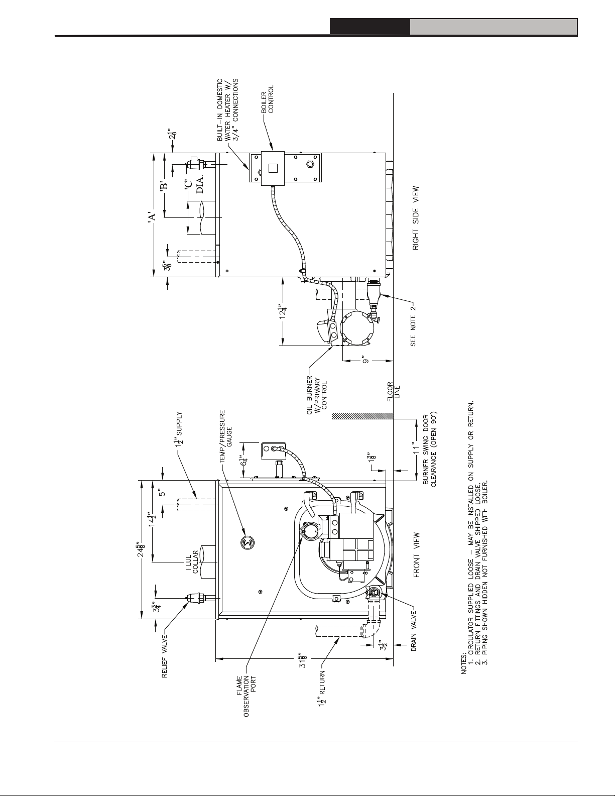
Table 1A: Dimensional Data
Boiler Series
Dimensions
"A" "B" "C" Round in Dia.
Approx.
Water Content
Gallons
FORCEVFO-3 17-3/8" 8-1/4" 5-7/8" 16 6
FORCEVFO-5 27-3/8" 13-3/8" 7-7/8" 24 8
Maximum Working Water Pressure: 30 PSI Shipped from Factory, 50 PSI Optional
Table 1B: Rating Data
Boiler
Model
Burner
Capacity
GPH MBH
(1)
Heating
Capacity
(2)
Ratings
MBH MBH
Net AHRI
(3)
FORCEVFO-3-075 0.75 105 92 80 87.0
FORCEVFO-3-100 1.00 140 122 106 86.3
FORCEVFO-4-120 1.20 168 148 129 87.0
FORCEVFO-4-150 1.50 210 182 158 86.0
FORCEVFO-5-175 1.75 245 214 186 86.4
FORCECFO-5-190 1.90 266 231 201 86.0
(1)
MBH refers to thousands of BTU per hour.
(2)
Based on standard test procedure prescribed by the United States Department of
Energy at combustion conditions of 13.0% CO2.
(3)
Net AHRI Ratings are based on piping and pickup allowance of 1.15 for water.
Recommended Minimum Chimney
Rectangle
in. x in.
Height ft.
8 x 8 15FORCEVFO-4 22-3/8" 10-7/8" 6-7/8" 20 7
AFUE
%
110547-01 - 4/20
5
FORCEVFO Installation & Service Manual
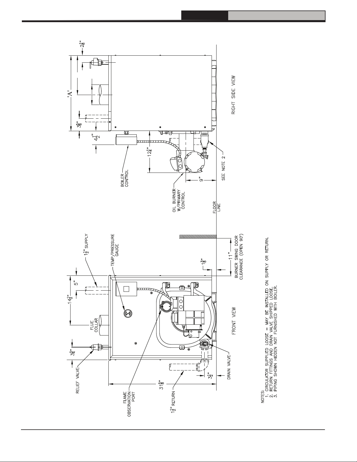
1 Product Description, Specification and Dimensional Data (continued)
'C'
'B'
DIA.
Figure 1-1: Water Boiler without Tankless Heater
6
110547-01 - 4/20
FORCEVFO Installation & Service Manual
1 Product Description, Specification and Dimensional Data (continued)
110547-01 - 4/20
Figure 1-2: Water Boiler with Rear Tankless Heater
7
2 Pre-Installation
FORCEVFO Installation & Service Manual
A. INSPECT SHIPMENT carefully for any signs of
damage.
1. All equipment is carefully manufactured,
inspected and packed. Our responsibility
ceases upon delivery of crated boiler to the
carrier in good condition.
2. Any claims for damage or shortage in shipment
must be filed immediately against the carrier
by the consignee. No claims for variances
from, or shortage in orders, will be allowed by
the manufacturer unless presented within sixty
(60) days after receipt of goods.
B. LOCATE BOILER in front of final position before
removing crate. See Figures 1-1 and 1-2.
1. LOCATE so that vent pipe connection to
chimney will be short and direct.
2. BOILER IS SUITABLE FOR INSTALLATION
ON COMBUSTIBLE FLOOR. Boiler cannot be
installed on carpeting.
3. FOR BASEMENT INSTALLATION, provide a
solid elevated base, such as concrete, if floor
is not level, or if water may be encountered on
floor around boiler.
4. PROVIDE SERVICE CLEARANCE of at least
24” clearance from front jacket panel for
servicing and removal of front tankless heater.
If boiler is equipped with a rear tankless heater,
provide at least 24" service clearance on the
right side of the boiler. Boiler flueways may be
cleaned either from the top. Provide at least
24" clearance from the top of the boiler for
cleaning flueways.
5. For minimum clearances to combustible
materials. See Figure 2-1.
C. PROVIDE COMBUSTION AND VENTILATION
AIR. Local and National Codes may apply and
should be referenced.
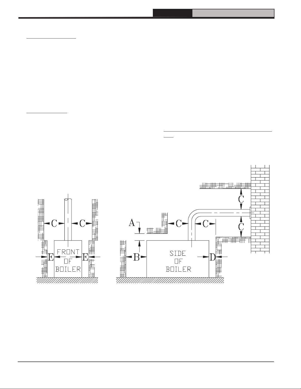
Figure 2-1: Minimum Installation Clearances To Combustible Materials (Inches)
NOTES:
1. Listed clearances comply with American
National Standard ANSI/NFPA 31, Installation
of Oil Burning Equipment.
2. FORCEVFO Series boilers can be installed
in rooms with clearances from combustible
material as listed above. Listed clearances
cannot be reduced for alcove or closet
installations.
8
3. For reduced clearances to combustible
material, protection must be provided as
described in the above ANSI/NFPA 31
standard.
110547-01 - 4/20

2 Pre-Installation (continued)
FORCEVFO Installation & Service Manual
NOTICE Clearance to venting is for single wall
vent pipe. If Type L vent is used, clearance may
be reduced to the minimum required by the vent
pipe manufacturer.
!
WARNING
Adequate combustion and ventilation air must
be provided to assure proper combustion and
to maintain safe ambient air temperatures.
DO NOT install boiler where gasoline or other
flammable vapors or liquids, or sources of
hydrocarbons (i.e. bleaches, fabric softeners,
etc.) are used or stored.
1. Determine volume of space (boiler room).
Rooms communicating directly with the
space in which the appliances are installed,
through openings not furnished with doors, are
considered a part of the space.
Volume(ft3) = Length(ft) x Width(ft) x Height(ft)
2. Determine total input of all appliances in the
space.
Add inputs of all appliances in the space and
round the result to the nearest 1000 BTU per
hour.
3. Determine type of space. Divide Volume by
total input of all appliances in space. If the
result is greater than or equal to 50 ft3/1000
BTU per hour, then it is considered an
unconfined space. If the result is less than
50 ft3/1000 BTU per hour then the space is
considered a confined space.
4. For boiler located in an unconfined space of a
conventionally constructed building, the fresh
air infiltration through cracks around windows
and doors normally provides adequate air for
combustion and ventilation.
5. For boiler located in a confined space or an
unconfined space in a building of unusually
tight construction, provide outdoor air.
a. Outdoor air may be provided with the
use of two permanent openings which
communicate directly or by duct with the
outdoors or spaces (crawl or attic) freely
communicating with the outdoors. Locate
one opening within 12 inches of top of
space. Locate remaining opening within
12 inches of bottom of space. Minimum
dimension of air opening is 3 inches. Size
each opening per following:
i. Direct communication with outdoors.
Minimum free area of 1 square inch
per 4,000 BTU per hour input of all
equipment in space.
ii. Vertical ducts. Minimum free area of
1 square inch per 4,000 BTU per hour
input of all equipment in space. Duct
cross-sectional area shall be same as
opening free area.
iii. Horizontal ducts. Minimum free area of
1 square inch per 2,000 BTU per hour
input of all equipment in space. Duct
cross-sectional area shall be same as
opening free area.
Alternate method for boiler located
within confined space. Use indoor air if
two permanent openings communicate
directly with additional space(s) of
sufficient volume such that combined
volume of all spaces meet criteria for
unconfined space. Size each opening
for minimum free area of 1 square inch
per 1,000 BTU per hour input of all
equipment in spaces, but not less than
100 square inches.
6. Louvers and Grilles of Ventilation Ducts
a. All outside openings should be screened
and louvered. Screens used should not be
smaller than 1/4 inch mesh. Louvers will
prevent the entrance of rain and snow.
b. Free area requirements need to consider
the blocking effect of louvers, grilles, or
screens protecting the openings. If the free
area of the louver or grille is not known,
assume wood louvers have 20-25 percent
free area and metal louvers and grilles have
60-75 percent free area.
c. Louvers and grilles must be fixed in the
open position, or interlocked with the
equipment to open automatically during
equipment operation.
110547-01 - 4/20
9
3 Packaged Boiler Assembly
A. REMOVE CRATE.
1. Remove all fasteners at crate skid.
2. Lift outside container and remove all other
inside protective spacers and bracing.
Remove draft regulator box and miscellaneous
trim bag containing safety or relief valve, and
pipe fittings.
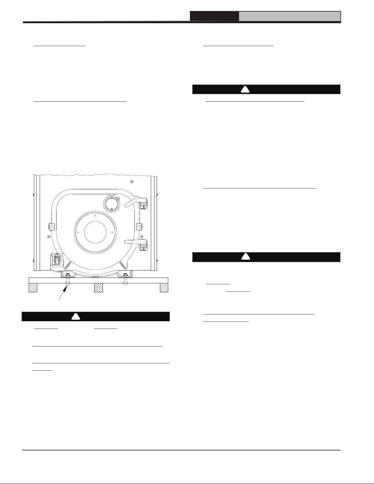
B. REMOVE BOILER FROM SKID.
1. Boiler is secured to base with 4 bolts, 2 in front
and 2 in rear of shipping skid, see Figure 3-1.
Remove all bolts.
2. Tilt boiler to right and to rear. Using right rear
leg as pivot, rotate boiler 90° in a clockwise
direction, and lower left side of boiler to floor.
Tilt boiler and remove crate skid. Care should
be exercised to prevent damage to jacket or
burner.
FORCEVFO Installation & Service Manual
E. INSTALL OIL BURNER.
1. Open burner carton and remove contents.
Refer to Table 15-1.
2. Place oil burner gasket on burner and align
holes.
CAUTION
!
Do not install burner without Gasket.
3. Remove three (3) 5/16-18 x 3/4” long cap
screws from burner swing door used for
mounting burner.
4. Insert oil burner into opening of burner swing
door. Align the top slotted hole in burner
flange with the top hole on the burner swing
door. Install one (1) cap screw.
5. Align remaining holes and install the two (2)
remaining cap screws.
F. INSTALL SAFETY OR RELIEF VALVE see
Figure 1-1.
1
Use ¾" NPT x 7
Safety or Relief Valve must be installed with
spindle in vertical position. Pipe discharge as
shown in Figures 4-2 and 4-3. Installation of the
safety or relief valve must be consistent with ANSI/
ASME Boiler and Pressure Vessel Code, Section
I V.
/4" nipple included in trim bag.
Figure 3-1 : Packaged Boiler Removal from Skid
CAUTION
!
DO NOT drop boiler. DO NOT bump boiler
jacket against floor.
C. MOVE BOILER TO PERMANENT POSITION
by sliding or walking.
D. INSPECT COMBUSTION CHAMBER TARGET
WALL.
1. Open burner swing door.
2. Using a flashlight, inspect the rear target wall.
The target wall should be rigidly secured to the
rear boiler section.
!
WARNING
Safety valve discharge piping must be piped
near floor to eliminate potential of severe burns.
DO NOT pipe in any area where freezing could
occur. DO NOT install any shut-off valves,
plugs or caps.
G. PACKAGED WATER BOILERS WITH
CIRCULATORS. If your boiler build comes with
factory supplied circulator and circulator is to be
mounted in supply piping connected directly to
1½" boiler supply tapping.
10
110547-01 - 4/20

4 Water Boiler Piping and Trim
FORCEVFO Installation & Service Manual
NOTICE Failure to pipe boiler as specified in this
manual may result in excessive system noise,
water line fluctuations and water carry over.
A. EVALUATE THE EXISTING WATER SYSTEM.
Design a piping system and install boiler which
will prevent oxygen contamination of boiler water
and frequent water additions.
1. There are many possible causes of oxygen
contamination such as:
a. Addition of excessive make-up water as a
result of system leaks.
b. Absorption through open tanks and fittings.
c. Oxygen permeable materials in the
distribution system.
2. In order to insure long product life, oxygen
sources must be eliminated. This can
be accomplished by taking the following
measures:
a. Repairing system leaks to eliminate the
need for addition of make-up water.
b. Eliminating open tanks from the system.
c. Eliminating and/or repairing fittings which
allow oxygen absorption.
d. Use of non-permeable materials in the
distribution system.
e. Isolating the boiler from the system water by
installing a heat exchanger.
WARNING
!
System supply and return piping must be
connected to correct boiler pipe.
U.S. Boiler Company recommends sizing
the system circulator to supply sufficient
flow (GPM) to allow a 20°F temperature
differential in the system. When sizing the
system circulator, the pressure drop of all
radiators, baseboard and radiant tubing and all
connecting piping must be considered.
CAUTION
!
Maintain minimum ½ inch clearance from hot
water piping to combustible materials.
B. CONNECT SYSTEM SUPPLY AND RETURN
PIPING TO BOILER. See Figures 4-2 and
4-3. Also, consult Residential Hydronic Heating
Installation and Design I=B=R Guide.
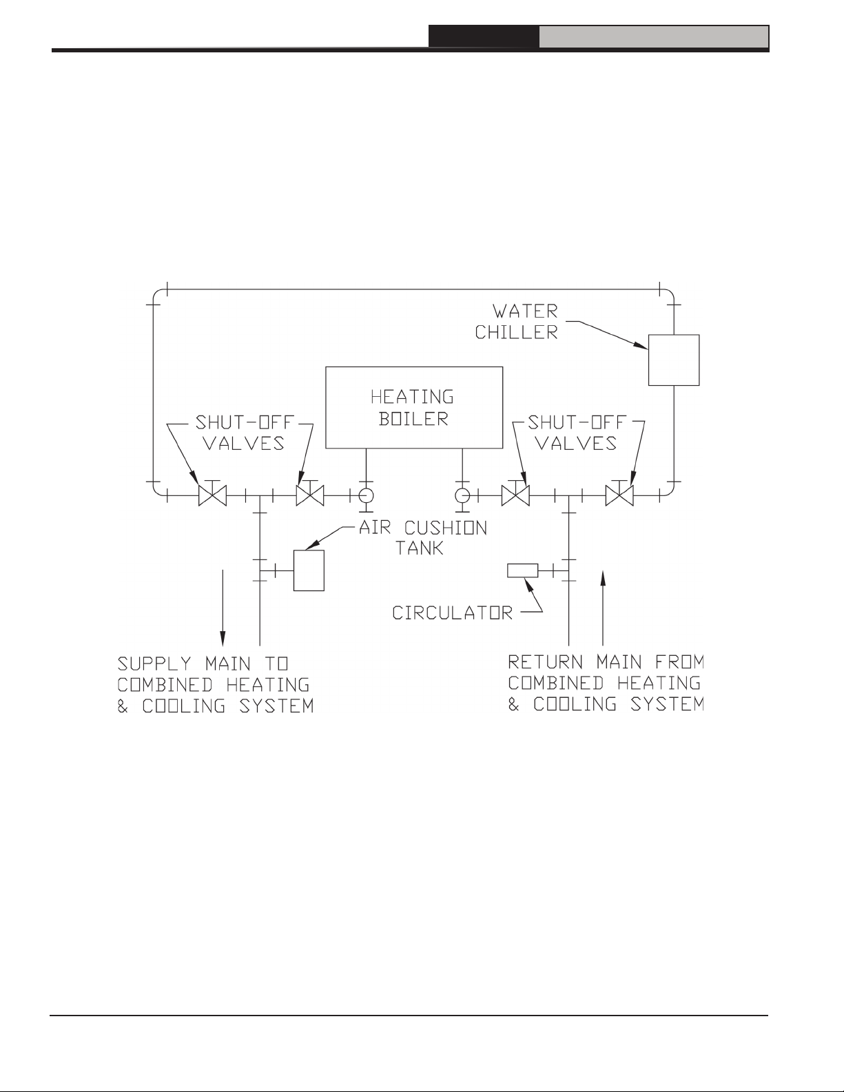
1. If this boiler is used in connection with
refrigeration systems, the boiler must be
installed so that the chilled medium is piped
in parallel with the heating boiler using
appropriate valves to prevent the chilled
medium from entering the boiler. See Figure
4-1. Also, consult Residential Hydronic
Heating Installation and Design I=B=R Guide.
2. If this boiler is connected to heating coils
located in air handling units where they may
be exposed to refrigerated air, the boiler piping
must be equipped with flow control valves
to prevent gravity circulation of boiler water
during the operation of the cooling system.
3. If boiler is used with an Indirect Domestic
Water Heater, install the Indirect Water Heater
as a separate heating zone. Refer to the
Indirect Water Heater Installation, Operating,
and Service Instructions for additional
information.
4. Use a boiler bypass if the boiler is to be
operated in a system which has a large
volume or excessive radiation where low boiler
water temperatures may be encountered (i.e.
converted gravity circulation system, etc.)
The bypass should be the same size as the
supply and return lines with valves located
in the bypass and return line as illustrated in
Figures 4-2 and 4-3 in order to regulate water
flow for maintenance of higher boiler water
temperature.
WARNING
!
The use of a low water cut-off device, while
not required unless radiation level is below the
boiler, is highly recommended.
5. If a Low Water Cut-Off (LWCO) is required, it
must be mounted in the system piping above
the boiler. The minimum safe water level of a
hot water boiler is just above the highest water
containing cavity of the boiler; that is, a hot
water boiler must be full of water to operate
safely. Refer to Appendix A at the rear of this
manual.
6. If it is required to perform a long term
pressure test of the hydronic system,
the boiler should first be isolated to avoid a
pressure loss due to the escape of air trapped
must first be removed from the boiler.
110547-01 - 4/20
11
4 Water Boiler Piping and Trim (continued)
To perform a long term pressure test including
the boiler, ALL trapped air must first be
removed from the boiler.
A loss of pressure during such a test, with no
visible water leakage, is an indication that the
boiler contained trapped air.
FORCEVFO Installation & Service Manual
12
Figure 4-1: Recommended Piping for Combination Heating and Cooling (Refrigeration) System
110547-01 - 4/20
4 Water Boiler Piping and Trim (continued)
FORCEVFO Installation & Service Manual
110547-01 - 4/20
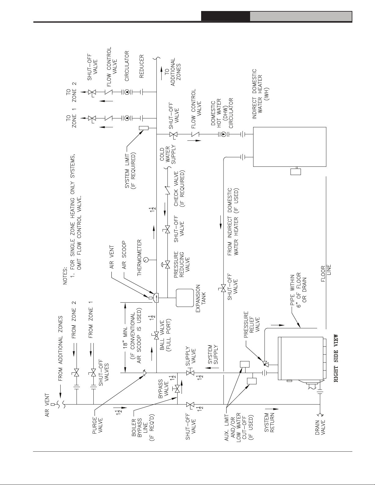
Figure 4-2: Recommended Water Piping for Circulator Zoned Heating System - Supply Side Circulators
13
4 Water Boiler Piping and Trim (continued)
FORCEVFO Installation & Service Manual
14
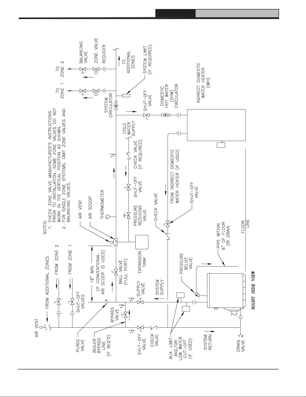
Figure 4-3: Recommended Water Piping for Zone Valve Zoned Heating System - Supply Side Circulator
110547-01 - 4/20

5 Tankless and Indirect Water Heater Piping
FORCEVFO Installation & Service Manual
A. CONNECT TANKLESS HEATER PIPING as
shown in Figure 5-1. See Table 5-2 for Tankless
Heater Rating.
WARNING
!
Install automatic mixing valve at tankless heater
outlet to avoid risk of burns or scalding due
to excessively hot water at fixtures. Adjust
and maintain the mixing valve in accordance
with the manufacturer's instructions. DO NOT
operate tankless heater without mixing valve.
THE FOLLOWING GUIDELINES SHOULD BE
FOLLOWED WHEN PIPING THE TANKLESS
HEATER:
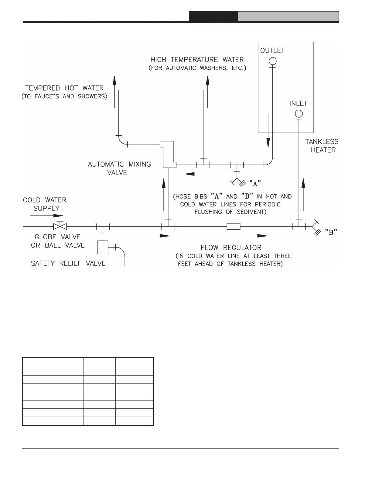
1. FLOW REGULATION — If flow through the
heater is greater than its rating, the supply of
adequate hot water may not be able to keep
up with the demand. For this reason a flow
regulator matching the heater rating should
be installed in the cold water line to the heater.
The flow regulator should preferably be located
below the inlet to the heater and a minimum of
3’ away from the inlet so that the regulator is
not subjected to excess temperatures that may
occur during “off” periods when it is possible
for heat to be conducted back through the
supply line. The flow regulator also limits
the flow of supply water regardless of inlet
pressure variations in the range of 20 to 125
psi.
2. TEMPERING OF HOT WATER — Installation
of an automatic mixing valve will lengthen the
delivery of the available hot water by mixing
some cold water with the hot. This prevents
the possibility of scalding hot water at the
fixtures. In addition, savings of hot water will be
achieved since the user will not waste as much
hot water while seeking a water temperature.
Higher temperature hot water required by
dishwashers and automatic washers is
possible by piping the hot water from the
heater prior to entering the mixing valve. The
mixing valve should be “trapped” by installing
it below the cold water inlet to heater to prevent
lime formation in the valve. Refer to Figure
16A.
3. FLUSHING OF HEATER — All water
contains some sediment which settles on the
inside of the coil. Consequently, the heater
should be periodically back washed. This
is accomplished by installing hose bibs as
illustrated and allowing water at city pressure
to run into hose bib A, through the heater, and
out hose bib B until the discharge is clear. The
tees in which the hose bibs are located should
be the same size as heater connections to
minimize pressure drop.
4. HARD WATER — A water analysis is
necessary to determine the hardness of your
potable water. This is applicable to some
city water and particularly to well water.
An appropriate water softener should be
installed based on the analysis and dealer’s
recommendation. This is not only beneficial to
the tankless heater but to piping and fixtures
plus the many other benefits derived from soft
water.
Use street elbow fittings in tankless in and out
connections to assure adequate clearance of
piping.
!
CAUTION
Use of hard water with a tankless coil will, over
a short period of time, reduce the output of the
coil, reduce flow due to increased pressure
drop and reduce the useful life of the coil.
110547-01 - 4/20
15
FORCEVFO Installation & Service Manual
5 Tankless and Indirect Water Heater Piping (continued)
Figure 5-1: Schematic Tankless Heater Piping
Table 5-2: Tankless Heater Data
Boiler
Model
FORCEVFO-3-075 3.00 4.7
FORCEVFO-3-100 3.25 5.6
FORCEVFO-4-120 3.75 7.2
FORCEVFO-4-150 4.00 8.0
FORCEVFO-5-175 4.25 8.8
FORCEVFO-5-190 4.75 9.6
Rating
(Gal/Min)
Drop (PSI)
16
Pressure
110547-01 - 4/20
 Loading...