

Page 1
Installation, Operating and Service Instructions for
• High Efficiency
• Oil-Fired, 3-Pass
FORCE™ OIL
Residential
Models:
• FORCEOL84-E
• FORCEOL115-E
• FORCEOL140-E
• FORCEOL182-E
Manual Contents Page
General Information ......................5
Pre-installation ..........................7
Packaged Boiler Assy. - Trim & Controls .....9
Water Boiler Piping .....................17
Indirect Water Heater Piping ..............21
Natural Draft Venting (Chimney) ...........22
Direct Venting/Air Intake Piping ...........26
Electrical ..............................33
Oil Piping .............................37
System Start-up ........................39
Operating .............................46
Service and Maintenance ................48
Boiler Cleaning ........................50
Troubleshooting ........................53
Service Parts ..........................55
Burner Specifications ...................66
Appendix A Aftermarket LWCO ...........66
• Water Boiler
• Natural Draft or Direct Vent
(140-E and 182-E)
As an ENERGY STAR® Partner, U.S. Boiler Company
has determined that the FORCEOL meet the
ENERGY STAR® guidelines for energy efficiency
established by the United States Environmental
Protection Agency (EPA).
TO THE INSTALLER:
Affix these instructions adjacent to boiler.
TO THE CONSUMER:
Retain these instructions for future reference.
106346-06 - 8/19
9700609
Page 2

FORCE
Installation, Operating & Service Manual
IMPORTANT INFORMATION - READ CAREFULLY
All boilers must be installed in accordance with National, State and Local Plumbing,
Heating and Electrical Codes and the regulations of the serving utilities. These
Codes and Regulations may differ from this instruction manual. Authorities having
jurisdiction should be consulted before installations are made.
In all cases, reference should be made to the following Standards:
USA BOILERS
A. Current Edition of American National Standard ANSI/NFPA 31, “Installation of Oil
Burning Equipment”, for recommended installation practices.
B. Current Edition of American National Standard ANSI/NFPA 211, “Chimneys, Fire
places, Vents, and Solid Fuel Burning Appliances”, For Venting requirements.
C. Current Edition of American Society of Mechanical Engineers ASME CSD-1,
“Controls and Safety Devices for Automatically Fired Boilers”, for assembly and
operations of controls and safety devices.
D. All wiring on boilers installed in the USA shall be made in accordance with the
National Electrical Code and/or Local Regulations.
The following terms are used throughout this manual to bring attention to the presence
of hazards of various risk levels, or to important information concerning product life.
!
DANGER
!
Indicates a hazardous situation that, if not
avoided, will result in death or serious injury.
!
WARNING
Indicates a hazardous situation that, if not
avoided, could result in death or serious injury.
NOTICE: This boiler has a limited warranty. The warranty for this boiler is valid only if the boiler has been
installed, maintained and operated in accordance with these instructions.
Surface rust on cast iron sections may be attributed to the manufacturing process as well as condensation
during storage. Surface rust is normal and does not affect the performance or longevity of a boiler.
Indicates a hazardous situation that, if not
avoided, could result in minor or moderate
injury.
NOTICE: Indicates special instructions on
installation, operation, or service which are
important but not related to personal injury
hazards.
CAUTION
2
106346-06 - 8/19
Page 3

FORCE
!
DANGER
DO NOT store or use gasoline or other flammable vapors or liquids in the vicinity of this or any other
appliance.
WARNING
!
• Improper installation, adjustment, alteration, service or maintenance can cause property damage, personal
injury or loss of life. Failure to follow all instructions in the proper order can cause personal injury or death.
Read and understand all instructions, including all those contained in component manufacturers manuals
which are provided with the appliance before installing, starting-up, operating, maintaining or servicing this
appliance. Keep this manual and literature in legible condition and posted near appliance for reference by
owner and service technician.
• This boiler requires regular maintenance and service to operate safely. Follow the instructions contained in
this manual.
• Installation, maintenance, and service must be performed only by an experienced, skilled and
knowledgeable installer or service agency.
• All heating systems should be designed by competent contractors and only persons knowledgeable in the
layout and installation of hydronic heating systems should attempt installation of any boiler.
• Installation is NOT complete unless a pressure relief valve is installed into the 3/4" tapping located on supply
piping that was installed into boss on top of rear section - See "Packaged Boiler Assy - Trim & Controls" and
"Water Boiler Piping" Sections of this manual for details.
• It is the responsibility of the installing contractor to see that all controls are correctly installed and are
operating properly when the installation is complete including verifying that the limit sensor is fully installed.
Failure to properly install Limit Sensor may result in property damage, personal injury or loss of life due to
elevated operating temperatures and/or pressures.
• This boiler is suitable for installation on combustible flooring. DO NOT install boiler on carpeting.
• DO NOT tamper with or alter the boiler or controls.
• Inspect flueways at least once a year - preferably at the start of the heating season. The inside of the
combustion chamber, the vent system and boiler flueways should be cleaned if soot or scale has
accumulated.
Installation, Operating & Service Manual
When cleaning this boiler, take precaution to avoid damage to burner swing door insulation. If damaged, or if
there is evidence of previous damage, burner swing door insulation must be replaced immediately.
• Oil Burner and Controls must be checked at least once a year or as may be necessitated.
• DO NOT operate unit with jumpered or absent controls or safety devices.
• DO NOT operate unit if any control, switch, component, or device has been subject to water.
• Boiler materials of construction, products of combustion and the fuel contain alumina, silica, heavy metals,
carbon monoxide, nitrogen oxides, aldehydes and/or other toxic or harmful substances which can cause
death or serious injury and which are known to the state of California to cause cancer, birth defects and
other reproductive harm. Always use proper safety clothing, respirators and equipment when servicing or
working nearby the appliance.
106346-06 - 8/19
3
Page 4

FORCE
WARNING
!
• This boiler contains very hot water under high pressure. DO NOT unscrew any pipe fittings nor attempt to
disconnect any components of this boiler without positively assuring the water is cool and has no pressure.
Always wear protective clothing and equipment when installing, starting up or servicing this boiler to prevent
scald injuries. DO NOT rely on the pressure and temperature gauges to determine the temperature and
pressure of the boiler. This boiler contains components which become very hot when the boiler is operating.
DO NOT touch any components unless they are cool.
• This boiler must be properly vented. The boiler must be connected to an approved chimney or vent system
in good condition. Serious property damage could result if the boiler is connected to a dirty or inadequate
chimney or vent system. The chimney must be inspected for any obstructions and cleaned prior to each
heating season. A clean and unobstructed chimney flue is necessary to produce the minimum draft required
to safely evacuate noxious fumes that could cause personal injury or loss of life. DO NOT operate boiler with
the absence of an approved vent system. Evidence of loose debris and or condensate induced stains at
the base of the chimney flue, connector or smokepipe joints may be signs of condensing flue gases. Flue
gas condensate is corrosive, which requires special consideration and must be addressed immediately.
Refer to "Natural Draft Venting (Chimney)" listed in Table of Contents below .
• This boiler needs fresh air for safe operation and must be installed so there are provisions for adequate
combustion and ventilation air.
• This boiler is supplied with controls which may cause the boiler to shut down and not re-start without service.
If damage due to frozen pipes is a possibility, the heating system should not be left unattended in cold
weather; or appropriate safeguards and alarms should be installed on the heating system to prevent damage
if the boiler is inoperative.
• This boiler is designed to burn No. 2 fuel oil only. DO NOT use gasoline, crankcase drainings, or any oil
containing gasoline. Never burn garbage or paper in this boiler. DO NOT convert to any solid fuel (i.e.
wood, coal). DO NOT convert to any gaseous fuel (i.e. natural gas, LP). All flammable debris, rags, paper,
wood scraps, etc., should be kept clear of the boiler at all times. Keep the boiler area clean and free of fire
hazards.
• All boilers equipped with burner swing door have a potential hazard which, if ignored, can cause severe
property damage, personal injury or loss of life. Before opening swing door turn off service switch to boiler
to prevent accidental firing of burner outside the combustion chamber. Be sure to tighten swing door
fasteners completely when service is completed.
Installation, Operating & Service Manual
4
106346-06 - 8/19
Page 5
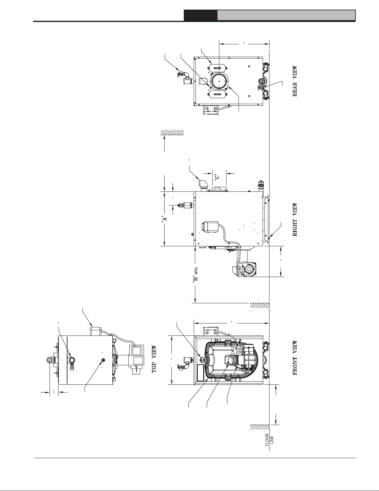
NOTES:
1. THIS DIMENSION INCREASES AND IS CONTROLLED BY SMOKEPIPE ARRANGEMENT.
2. DRAIN VALVE AND RELIEF VALVE/FITTINGS SHIPPED LOOSE.
3. BOILER SHIPPED WITH STANDARD RIGHT HAND HINGE CONFIGURATION, BUT CAN
BE CONVERTED TO LEFT HAND HINGE. APPLY CLEARANCE ACCORDINGLY.
1 General Information
RELIEF
VALVE
SMOKEBOX
FORCE
TAPPING
PRESURE
Installation, Operating & Service Manual
"
3
CLEAN
OUT COVER
8
21
DRAIN VALVE
"NPT SYSTEM
1
2
1
COLLAR
SMOKEBOX COLLAR
SPANNER BAR W/
ADJUSTABLE LEGS
"
1
4
13
Figure 1: FORCE OIL Dimensions
"
8
7
31
CONNECTION
"NPT SYSTEM RETURN
1
2
1
12" MIN
CLEARANCE
(SEE NOTE 1)
REAR SERVICE
4
3
5 "
BOILER
CONTROL
SUPPLY
CONNECTION
GAUGE
TEMP/PRESSURE
FRONT SERVICE
DIA.
CLEARANCE
(FLUEWAY CLEANING)
"
11
16
3
106346-06 - 8/19
4
3
20 "
WELL
IMMERSION
PORT
DOOR
FLAME
BURNER
SWING
OBSERVATION
BURNER
BECKETT AFG
(SHOWN)
19" MIN.
(SEE NOTE 3)
(FULLY OPEN)
BURNER SWING
DOOR CLEARANCE
5
Page 6

1 General Information (continued)
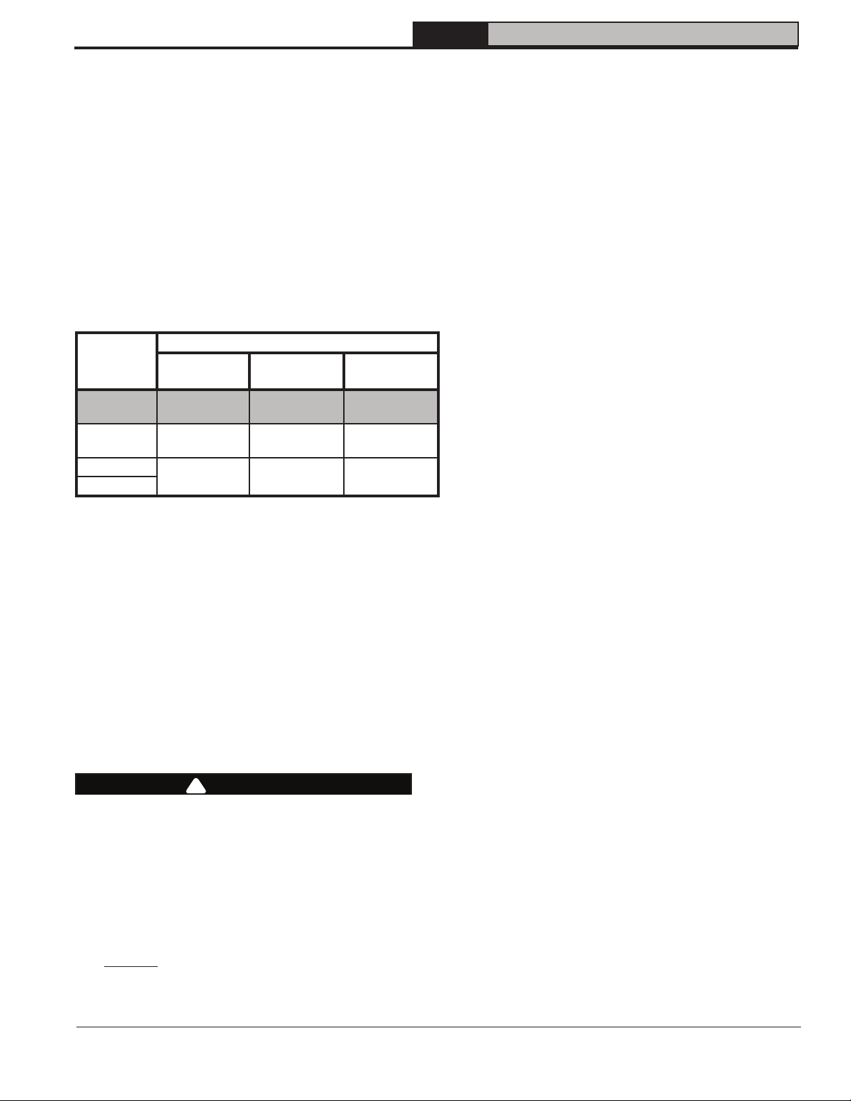
Table 1A: Dimensional Data (See Figure 1)
FORCE
Installation, Operating & Service Manual
Dimensions See Figure 1
Boiler Model
FORCEOL084-
E/115-E
FORCEOL140-E 23” 24” 6” 11.08 20.29 567
FORCEOL182E 29” 30” 6” 14.46 27.29 660
NOTE: 1. Maximum Working Pressure: Water: 30 PSI Shipped From Factory (Standard),
50 PSI Optional
Table 1B: Rating Data
Boiler Model
FORCEOL084-E 0.60 84 6 8 x 8 15 N/A N/A
FORCEOL115-E 0.80 115 6 8 x 8 15 N/A N/A
FORCEOL140-E 1.00 140 6 8 x 8 15 106401-01 5
FORCEOL182-E 1.30 182 7 8 X 8 15 106401-01 5
“A” “B” “C”
17” 24” 5” 7.70 13.29 475
Burner Capacity
GPH MBH
In. Dia.
Minimum Chimney
Recommendations
Round
Water Content -
Rectangle
In. x In.
Gallons
Height
Ft.
Heat Transfer
Surface Area -
Sq. Ft.
Direct Vent System
Kit
Part Number
Actual Shipping
Vent Connector
Dia. Inch
Weight (LB.)
6
106346-06 - 8/19
Page 7

2 Pre-Installation
FORCE
Installation, Operating & Service Manual
A. INSPECT SHIPMENT carefully for any signs of
damage.
1. All equipment is carefully manufactured,
inspected and packed. Our responsibility ceases
upon delivery of crated boiler to the carrier in
good condition.
2. Any claims for damage or shortage in shipment
must be filed immediately against the carrier by
the consignee. No claims for variances from,
or shortage in orders, will be allowed by the
manufacturer unless presented within sixty (60)
days after receipt of goods.
B. LOCATE BOILER in front of final position before
removing crate. See Figure 1.
1. LOCATE so that vent pipe connection to
chimney will be short and direct.
2. BOILER IS SUITABLE FOR INSTALLATION
ON COMBUSTIBLE FLOOR. Boiler cannot be
installed on carpeting.
3. FOR BASEMENT INSTALLATION, provide a
solid elevated base, such as concrete, if floor is
not level, or if water may be encountered on floor
around boiler.
4. PROVIDE RECOMMENDED SERVICE
CLEARANCE, if applicable, as follows:
a. Clearance from Jacket Front Panel -
• 24" for servicing burner
• 24" for flueway cleaning (FORCEOL084-E
through FORCEOL140-E).
• 30" for flueway cleaning (FORCEOL182-E)
b. Clearance from Jacket Left Side Panel -
• 19" for burner swing door, if opened fully
with burner mounted, otherwise 1" with
burner removed
• 12" access clearance to service rear of
boiler if right side clearance is less
than 12"
• 3" minimum if right side clearance is 12"
or larger to access and service rear of
boiler.
c. Clearance from Jacket Right Side Panel -
• 3" minimum if left side clearance is 12" or
larger to access and service rear of boiler.
d. Clearance from Jacket Rear Panel -
• 12" minimum for rear smokebox cleaning
(NOTE: This dimension will also be
controlled by horizontal to vertical to
horizontal smokepipe arrangement Chimney Vent (see Figures 2A and 13).
• 24" for rear smoke box cleaning and
disconnecting vent pipe from boiler
adaptor for servicing (if required) - Direct
Vent (see Figures 2B and 25).
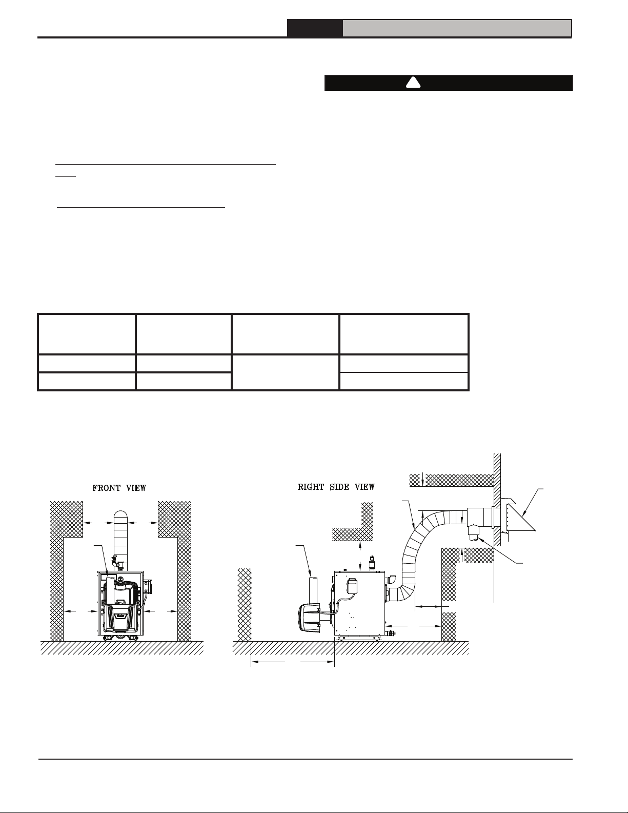
18"18"
6" 6"
24"
Figure 2A: Chimney Vent - Minimum Installation Clearances To Combustible Materials (Inches)
NOTES: 1. Listed clearances comply with American National
Standard ANSI/NFPA 31, Standard for the Installation of
Oil Burning Equipment.
2. FORCE OIL boilers can be installed in rooms with
clearances from combustible material as listed above.
Listed clearances cannot be reduced for alcove or
closet installations.
106346-06 - 8/19
18"
18"
6"
3. For reduced clearances to combustible material,
protection must be provided as described in the above
ANSI/NFPA 31 standard.
18"
18"
7
Page 8
2 Pre-Installation (continued)
FORCE
Installation, Operating & Service Manual
5. For minimum clearances to combustible
materials. See Figures 2A and 2B.
NOTICE: Clearance to venting is for single wall
vent pipe. If Type L vent is used, clearance may
be reduced to the minimum required by the vent
pipe manufacturer.
C. PROVIDE COMBUSTION AND VENTILATION
AIR. Local and National Codes may apply and
should be referenced.
D. DIRECT VENT CONFIGURATIONS requires:
1. Beckett NX Burner
2. Direct Vent conversion Kit
3. Double Wall Flex Oil Vent Pipe (FOVP)
Table 2: Direct Vent Configuration Components
Boiler
Model
Beckett NX
Oil Burner
Part No.
FORCEOL140-E 106109-03
FORCEOL182-E 103369-01
Direct Vent
Conversion Kit
Part No.
106401-01
WARNING
!
Adequate combustion and ventilation air must
be provided to assure proper combustion and
to maintain safe ambient air temperatures.
Do not install boiler where gasoline or other
flammable vapors or liquids, or sources of
hydrocarbons (i.e. bleaches, fabric softeners,
etc.) are used or stored.
FOVP Carton Part No.
100212-02 - 10 ft.
100214-02 - 20 ft.
3"3"
AIR
INTAKE
PIPING
6"6"
AIR INTAKE
PIPING
(REMOVED
FOR CLARITY)
24"
Figure 2B: Direct Vent - Minimum Installation Clearances To Combustible Materials (Inches)
NOTES: 1. Listed clearances comply with American National
Standard ANSI/NFPA 31, Standard for the Installation of
Oil Burning Equipment.
2. FORCE OIL boilers can be installed in rooms with
clearances from combustible material as listed above.
Listed clearances cannot be reduced for alcove or closet
installations.
8
FDVS
AIR
INTAKE
PIPING
DIRECT
VENT
VENT
PIPING
6"
3. For reduced clearances to combustible material,
protection must be provided as described in the above
ANSI/NFPA 31 standard.
3"
3"
3"
6"
106346-06 - 8/19
Page 9
FORCE
Installation, Operating & Service Manual
3 Packaged Boiler Assembly - Trim & Controls
A. REMOVE CRATE.
1. Remove all fasteners at crate skid.
2. Lift outside container and remove all other
inside protective spacers and bracing.
Remove miscellaneous parts carton.
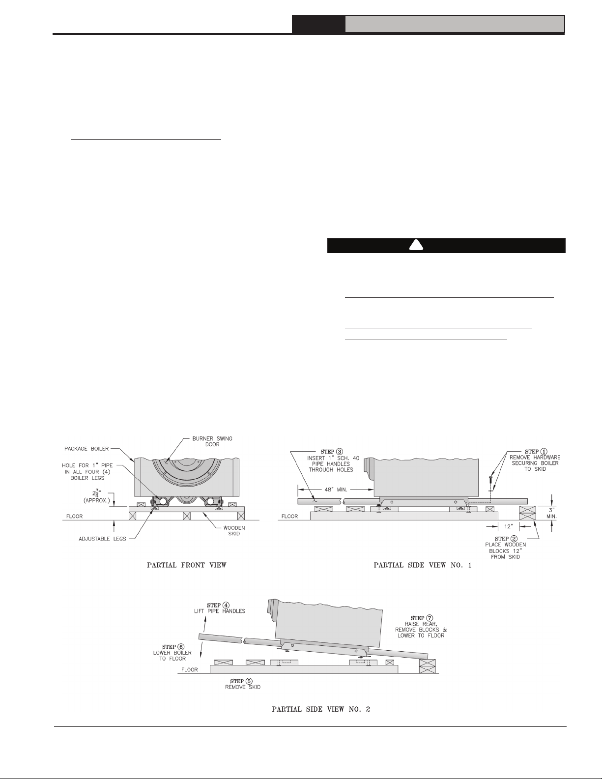
B. REMOVE BOILER FROM SKID.
1. To reduce the risk of damage to boiler jacket,
use the following procedure to remove from
skid, see Figure 3:
Step 1. Boiler is secured to base with (4) 5/16"
cap screws, (2) in front and (2) in rear of
shipping skid, see Figure 3. Remove all
securing hardware.
Step 2. Place wooden block(s) 12" from rear of
skid as shown (one piece 4" x 4" x 16" lg. or
two pieces of 2" x 4" x 16" lg.)
Step 3. Insert 1" Sch. 40 pipe handles through
leg hole in front and rear legs. Center end
of pipe on wooden blocks as shown in
Figure 3.
NOTE: Pipe handles should extend a
minimum of 48" beyond jacket front panel
for best leverage.
Step 4. Using the pipe handles, lift boiler until
adjustable legs are elevated above the
deck boards.
Step 5. Remove skid from underneath the
boiler.
Step 6. Lower pipe handles until front
adjustable legs touch floor. If necessary,
place wooden blocks under front legs
before lowering to provide hand clearance.
Step 7. To lower rear of boiler, tilt unit slightly
forward by pushing on smokebox collar or
lift pipes protruding through rear legs until
wooden blocks can be removed (see Figure
3). Slowly allow the weight of the boiler to
tilt backward until rear legs rest on floor.
Step 8. If wood block was placed under front
legs, lift pipe handles, remove wooden
block and lower front legs to floor. Remove
pipe handles.
CAUTION
!
Do not drop boiler. Do not bump boiler jacket
against floor.
C. MOVE BOILER TO PERMANENT POSITION
by sliding or walking.
D. PROCEDURE TO OPEN, CLOSE AND
SECURE BURNER SWING DOOR
Throughout this manual you will be instructed to
open and close the burner swing door for various
reasons. There is a proper and improper method
to closing and securing the burner swing door
opened for inspection, cleaning or field service.
1. TO OPEN BURNER SWING DOOR
(see Figures 4A and 4B).
106346-06 - 8/19
Figure 3: Packaged Boiler Removal from Skid
9
Page 10
FORCE
Installation, Operating & Service Manual
3 Packaged Boiler Assembly - Trim & Controls (continued)
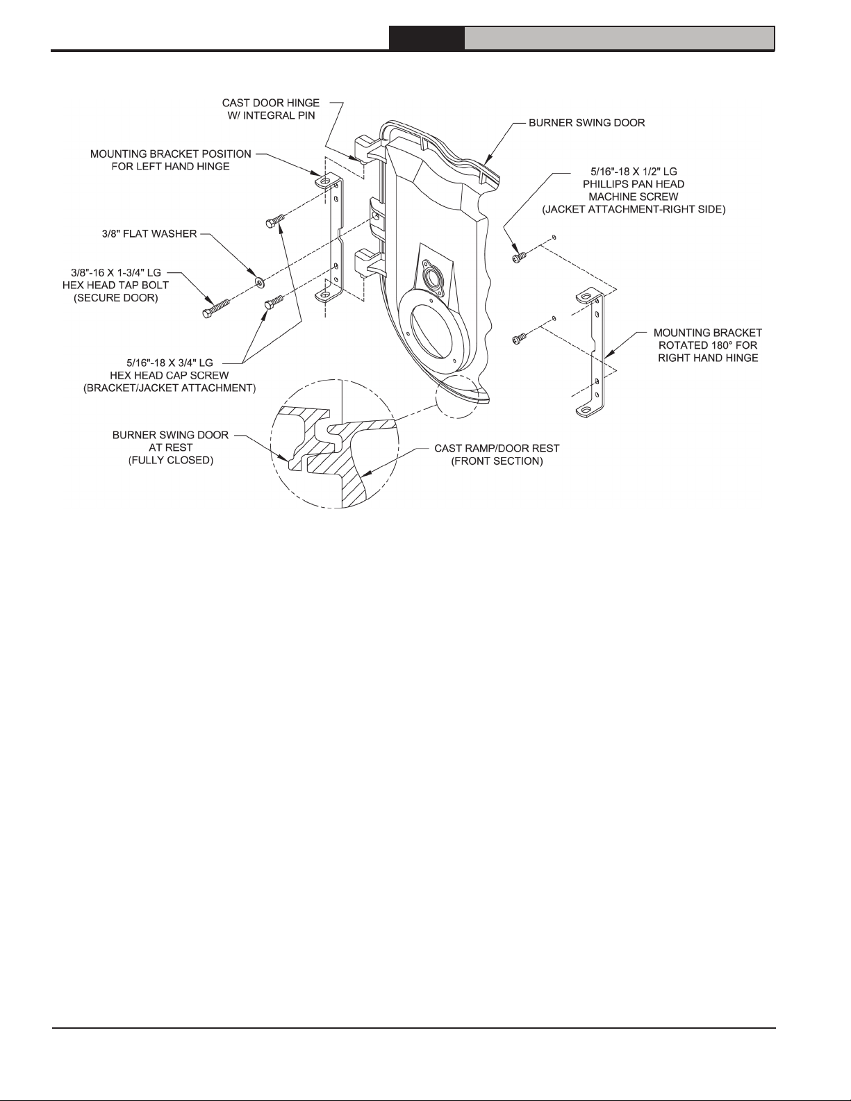
Figure 4A: Partial Front View - Burner Swing Door Mounted to Boiler - Fully Closed and Secured
Step 1. Loosen but do not remove left side
latching hardware (3/8" x 1-3/4" lg. tap bolt).
Step 2. Loosen and remove right side latching
hardware (3/8" x 1-3/4" lg. tap bolt and
washer).
Step 3. Remove left side latching hardware
(3/8" x 1-3/4" lg. tap bolt and washer).
Step 4. Disconnect power from boiler.
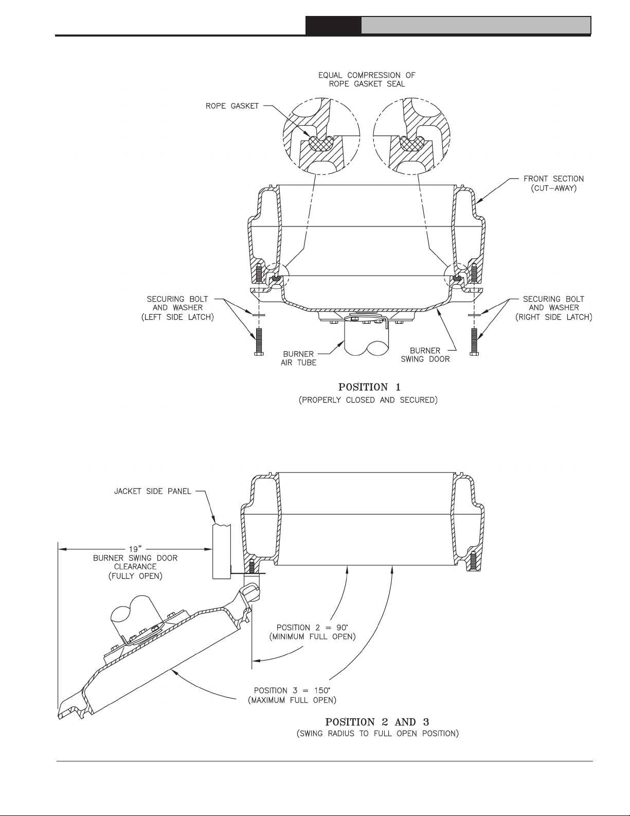
Step 5. Door can be swung to the fully open
position, approximately 90° to 120°, with the
burner mounted providing that there is 19"
of clearance to the adjacent wall, see Figure
1.
NOTE: If reduced clearance prevents the
door from opening fully, one of the following
can provide full access:
a. Burner can be removed to allow full
rotation of door.
b. Door with burner mounted can be lifted
off mounting bracket and set aside
during servicing.
c. The door mounting hardware is
reversible from left side hinge (as
shipped) to right side hinge.
To reverse hinge arrangement (see
Figure 4A):
• Lift door off mounting bracket and set
aside.
• Remove mounting bracket and
hardware from left side.
• Remove upper jacket front panel
retaining screw (5/16" x 1/2" lg. Phillip
Pan head machine screw) from right
side of door and re-install in vacated
upper mounting bracket tapping. Do
not tighten.
• Move lower jacket panel retaining
screw from right side to left tapping.
Do not tighten.
• Rotate door mounting bracket 180°.
Insert 5/16" cap screw through top
hole in bracket and install in upper
vacated jacket hole on right side of
door.
• Install second 5/16" cap through
bracket hole into lower vacated
tapping on right side.
• Tighten both sets of hardware to
secure jacket and mounting bracket.
• Lift door and place integral cast hinge
pins on door into slotted mounting
bracket holes.
10
106346-06 - 8/19
Page 11
FORCE
Installation, Operating & Service Manual
3 Packaged Boiler Assembly - Trim & Controls (continued)
Figure 4B: Top View - Burner Swing Door Mounted to Cast Iron Block Assembly (Jacket Removed for Clarity)
106346-06 - 8/19
11
Page 12
FORCE
Installation, Operating & Service Manual
3 Packaged Boiler Assembly - Trim & Controls (continued)
2. Perform routine inspection, service or cleaning
as necessary.
3. TO CLOSE BURNER SWING DOOR (see
Figures 4A and 4B):
Step 1. From the fully open position, rotate
Burner Swing Door to the closed position.
Step 2. If necessary, place your right hand
under the burner air tube to lift upward. Lift
the door up unto the built-in cast ramp/door
rest (protruding from the bottom of the front
section casting - see Figure 4A).
Step 3. Use one hand to help hold door in
position by lifting up on rear burner housing
or applying pressure directly to the door
while re-installing the securing hardware
with your opposite hand. Always install
right side latching hardware (3/8"-16 x
1-3/4" lg. tap bolt and flat washer) first,
then install left side hinge hardware (3/8"16 x 1-3/4" lg. tap bolt and flat washer)
second. Apply additional pressure while
hand tightening the hardware as far as
possible, then release the pressure.
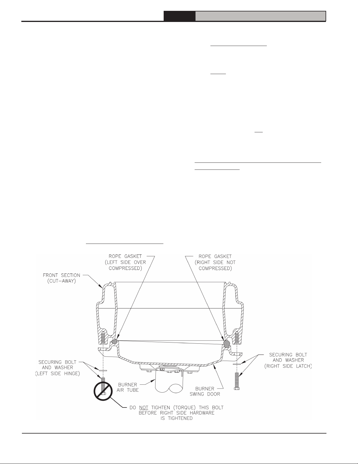
NOTICE: When securing burner swing door
make sure door is drawn-in equally on both sides.
Step 4. Use a hand wrench to tighten door
hardware and always start with the right
side cap screw first. Use an alternating
tightening method from right side tap bolt to
left side tap bolt to tighten door equally until
sealed without applying excessive torque.
Never tighten left side flange bolt first or
tighten either piece of hardware 100%
without using the alternating tightening
method described above.
Failure to follow the prescribed procedure
could cause thread damage to casting or
a leak in the door seal. If left side tap bolt
is tightened before right side tap bolt, right
side of door can not be drawn-in to provide
an air tight seal, as shown in Figure 4C.
Applying excessive torque will only cause
thread damage.
E. INSPECT SWING DOOR INSULATION AND
ROPE GASKET.
1. Open burner swing door using procedure
previously outlined in Paragraph D of this
section.
2. Inspect fiberglass rope located on the swing
door. The rope must be evenly distributed
around the perimeter of the door groove and
cannot bunch or overhang. There must not be
a gap where the two ends of the rope meet.
Repair or replace if the rope is damaged or if
there is a gap between the ends.
12
Figure 4C: Top View - Burner Swing Door Fully Closed but Not Properly Secured or Sealed
106346-06 - 8/19
Page 13
FORCE
Installation, Operating & Service Manual
3 Packaged Boiler Assembly - Trim & Controls (continued)
3. Inspect burner swing door insulation for
damage and proper type.
By design, cast bars on front section between
the combustion chamber and between the left
and right side 2
make an impression in door insulation to seal
the chambers.
If insulation is damaged, it must be replaced.
4. Do not close and secure door at this time,
proceed to Field Assembly Details, Paragraph
F.
F. FIELD ASSEMBLY OF BOILER TRIM AND
CONTROLS
Open miscellaneous parts carton and remove
contents. Identify the components using the
illustrations (see Figure 5) throughout the
assembly sequence outlined below as it applies
to your installation.
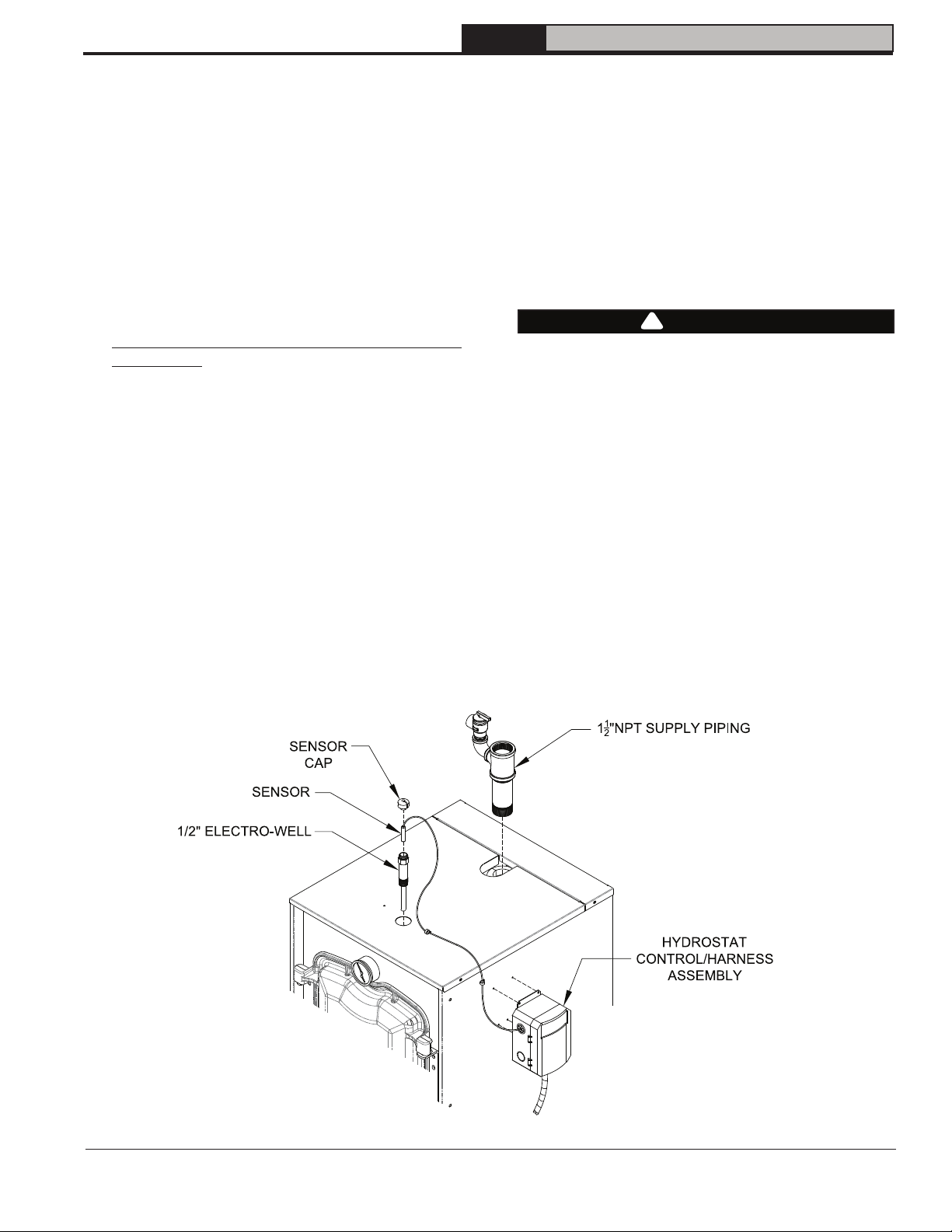
1. Install supply piping and relief valve, refer to
Figures 1 and 5.
Step 1. Locate the supply piping supplied
with boiler. Apply thread sealant to all
joints prior to assembly. Thread 1½"
NPT x 6" long supply nipple into 1½"
NPT tapping on the topside of the rear
section. Thread 1½" x 1½" x ¾" NPT tee
onto 6" nipple. Tighten all joints until
watertight and ¾" NPT connection on
tee is positioned to allow clearance for
relief valve discharge.
nd
and 3rd pass flueway should
Step 2. Locate the relief valve piping
supplied with boiler. Apply thread
sealant to all joints prior to assembly.
Thread the ¾" NPT street elbow onto
tee listed above. Install relief valve
into street elbow. Tighten all joints until
watertight and relief valve is positioned
to allow clearance for discharge.
Installation of the relief valve must be
consistent with ANSI/ASME Boiler and
Pressure Vessel Code, Section IV.
WARNING
!
Safety valve discharge piping must be piped
near floor to eliminate potential of severe burns.
Do not pipe in any area where freezing could
occur. Do not install any shut-off valves, plugs
or caps.
2. Install Boiler Control
(Hydrolevel HydroStat 3250 Plus)
Step 1. Locate the HydroStat/Harness
Assembly. Refer to the 36” Remote
Mounting Kit instructions (Included
in the 36” Remote Mounting Kit, P/N
105288-01) located in the Misc. Parts
Carton. Secure HydroStat 3250 Plus
control to the hinge side Side Panel with
supplied sheet metal screws as shown
in Figure 5.
106346-06 - 8/19
Figure 5: Supply Piping and HydroStat 3250 Plus Control Assembly Details
13
Page 14
FORCE
Installation, Operating & Service Manual
3 Packaged Boiler Assembly - Trim & Controls (continued)
Figure 6: Limit Sensor Insertion
Step 2. Locate (2) 5/8” cable clamps in
parts carton. Secure burner wiring
harness to front of jacket right side
panel with cable clamps and existing
jacket screws at top and mid-point.
Step 3. Locate the sensor (included in the
36” Remote Mounting Kit). Carefully
connect sensor into the HydroStat
3250 Plus circuit board by pressing
connector on sensor unit into mating
connector on circuit board. Fish the
sensor through top knockout; allow
adequate slack in sensor cable. Insert
sensor into Electro-well located in the
front section until it rests against the
bottom of the well. Secure sensor to
Electro-well with supplied well cap
(included in the 36” Remote Mounting
Kit).
Step 4. Locate (2) 3/16” cable clamps in
parts carton. Secure sensor wire to top
jacket panel and side jacket panel with
cable clamps with self-tapping sheetmetal screws (included) as shown in
Figure 5.
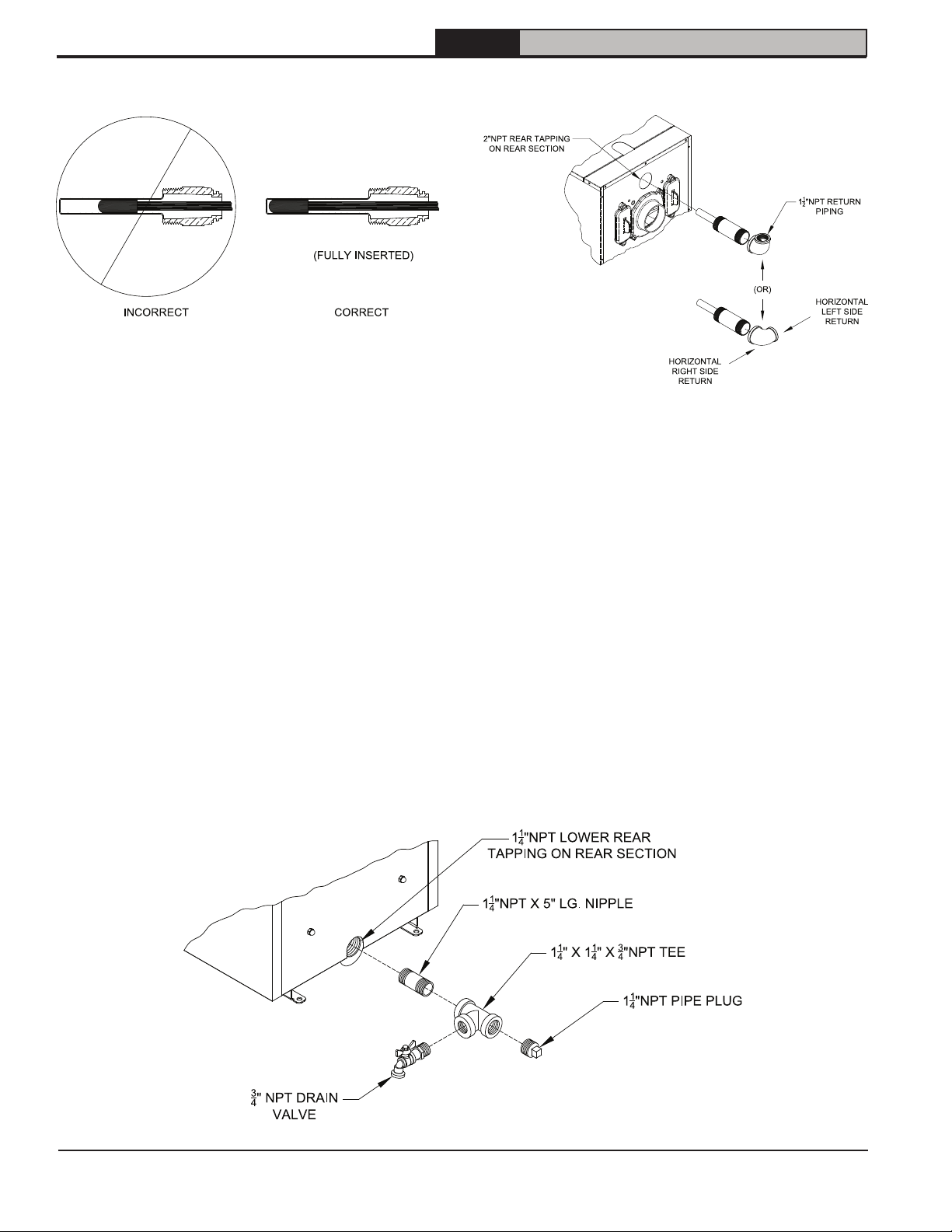
Figure 7: Return Injector Piping and
Relief Valve Assembly Details
3. Install return injector piping and relief valve, refer
to Figure 7.
Locate the return pipe fittings and injector. Apply
sealant to the 2” NPT injector threads. Insert
injector into 2” NPT upper rear tapping on rear
section. Thread 2” NPT x 1-1/2” Reducing Elbow
onto 2” NPT injector.
NOTE: Based on system return piping and
access to service boiler, see Figures 1,
10A and 10B, predetermine if injector
piping orientation is to be positioned for
vertical, horizontal left or horizontal right
side return piping as shown in Figure 7.
4. Install drain valve, see Figure 8.
Step 1. Apply pipe sealant to both ends
of 1-1/4" NPT x 5" lg. nipple. Thread
nipple into 1-1/4" NPT lower rear
tapping on rear section.
14
Figure 8: Piping Arrangement for Drain Valve and Indirect Water Heating Return
106346-06 - 8/19
Page 15
FORCE
Installation, Operating & Service Manual
3 Packaged Boiler Assembly - Trim & Controls (continued)
Step 2. Thread 1-1/4" x 1-1/4" x 3/4" NPT
tee on opposite end of 5" lg. nipple
installed in Step a.
NOTE: Based on access for servicing
and location of sewer or floor drain,
when tightening these fittings,
determine if drain valve is to be located
on the left or right side.
Tighten nipple and tee into 1-1/4" NPT
lower rear tapping on rear section
until joints are water tight for desired
position.
Table 3: Baffle Usage
Baffle Usage
Boiler Model
FORCEOL084-E
FORCEOL115-E
FORCEOL140-E
FORCEOL182-E
nd
2
Pass 3rd Pass
[2]
P/N 102066-01
[2]
P/N 109902-01
[2]
P/N 100042-01
None None
[2]
P/N 100081-01
None None
Combustion
Chamber
P/N 109901-01
Step 3. Apply sealant to 3/4" NPT thread
on drain valve. Thread into 3/4" NPT
tapping on side outlet of tee. Use hex
nut portion to tighten valve until water
tight.
5. Connect Field Wiring.
Connect the field wiring from the circulator to
the HydroStat 3250 control. Make the wiring
connections as shown on Figures 27 and 28.
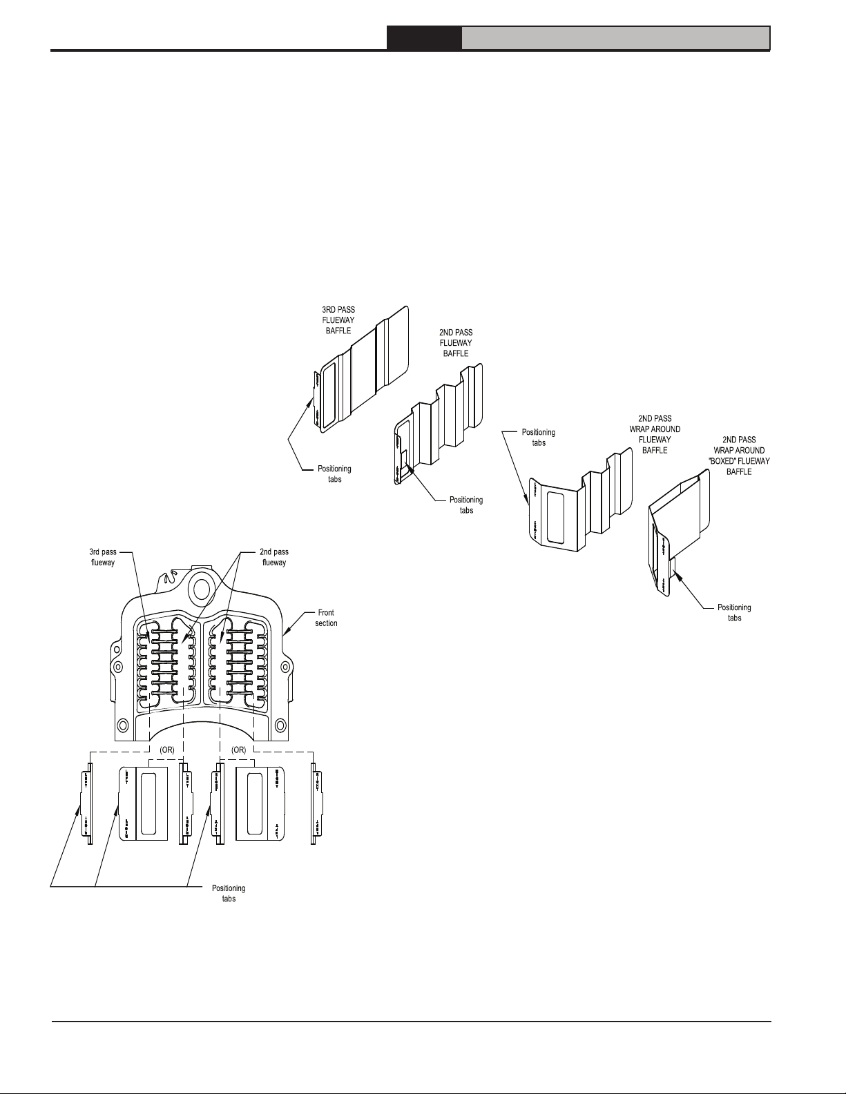
6. Installing stainless steel flueway baffles. Baffle
requirements differ from model to model, see
Table 3.
NOTE: Read caution statement before
proceeding.
CAUTION
!
These baffles will generate higher efficiencies
and lower stack temperatures. Under certain
conditions, a lower gross stack temperature
entering the chimney has the potential to
be cooled below the dew point and create
condensate on interior surfaces. Flue gas
condensate is corrosive, which requires
special consideration and must be addressed
immediately.
DO NOT install baffles until you have read
Sections VI and VII, completely (venting
details).
[1]
Install stainless steel baffles provided in
miscellaneous parts carton as follows, refer to
Table 3 and Figure 9:
•
FORCEOL084E - To install flueway baffle
in 2nd pass on left side of boiler, hold
baffle with word "Left" readable at the
top. Slide baffle in flueway until position
tab touches fins on left side of 2nd pass
flueway. To install flueway baffle in 2nd
pass flueway on right side of boiler, hold
baffle with word "Right" readable at the
top. Slide baffle in flueway until position
tab touches fins on right side of 2nd
pass flueway.
• Model EMP115E - To install flueway
baffle in 3
rd
pass on left side of boiler,
hold baffle with the word "Left" readable
at the top. Slide baffle in flueway until
position tab touches fins on left side
of 3rd pass flueway. To install flueway
baffle in 3rd pass flueway on right side
of boiler, hold baffle with word "Right"
readable at the top. Slide baffle in
flueway until position tab touches fin on
right side of 3
rd
pass flueway. To install
flueway baffle in 2nd pass on left side
of boiler, hold baffle with word "Left"
readable from the top. Slide baffle in
flueway until position tb touches fins on
left side of 3rd pass flueway. To install
flueway baffle in 2nd pass flueway on
right side of boiler, hold baffle with word
"Right" readable at the top. Slide baffle
in flueway until position tab touches fins
on right side of 3rd pass flueway.
To install combustion chamber Ring,
set ring in the front section of the
combustion chamber.
• FORCEOL140-E and FORCEOL182-E To
install flueway baffle in 2nd pass flueway
on left side of boiler, hold baffle with
word "Left" readable at the top. Slide
baffle in flueway until position tab
touches fins on right side of 2nd pass
flueway. To install flueway baffle in 2nd
pass flueway on right side of boiler, hold
baffle with word "Right" readable at the
top. Slide baffle in flueway until position
tab touches fins on left side of 2nd pass
flueway.
NOTE: 2nd and 3rd pass flueway baffle are not
interchangeable.
106346-06 - 8/19
15
Page 16
FORCE
Installation, Operating & Service Manual
3 Packaged Boiler Assembly - Trim & Controls (continued)
7. Close the burner swing door and securely seal
the door to the boiler front section by reinstalling
the hardware and securing the door using
procedure previously outlined in Paragraph D
of this section.
NOTICE: When securing burner swing door
make sure door is drawn-in equally on both sides.
16
Figure 9: Baffle Orientation in Flueways
106346-06 - 8/19
Page 17
FORCE
Installation, Operating & Service Manual
4 Water Boiler Piping
NOTICE: Failure to pipe boiler as specified in this manual may result in excessive system noise.
A. EVALUATE THE EXISTING WATER
SYSTEM.
Design a piping system and install boiler which
will prevent oxygen contamination of boiler water
and frequent water additions.
1. There are many possible causes of oxygen
contamination such as:
a. Addition of excessive make-up water as a
result of system leaks.
b. Absorption through open tanks and fittings.
c. Oxygen permeable materials in the
distribution system.
2. In order to insure long product life, oxygen
sources must be eliminated. This can
be accomplished by taking the following
measures:
a. Repairing system leaks to eliminate the
need for addition of make-up water.
b. Eliminating open tanks from the system.
c. Eliminating and/or repairing fittings which
allow oxygen absorption.
d. Use of non-permeable materials in the
distribution system.
e. Isolating the boiler from the system water by
installing a heat exchanger.
WARNING
!
System supply and return piping must be
connected to correct boiler manifolds.
U.S. Boiler Company, Inc. recommends sizing
the system circulator to supply sufficient flow
(GPM) to allow a 20°F temperature differential in
the system. When sizing the system circulator,
the most restrictive single zone should be used
to determine maximum pressure drop.
CAUTION
!
Maintain minimum ½ inch clearance from hot
water piping to combustible materials.
3. In order to insure long product life, operate boiler
at appropriate flow rate to minimize areas of
overheating
a. Design system to ensure that the flow is above
the limit called for in Table 4.
b. Maintain a constant boiler pressure of 12 PSI.
.
Table 4: Minimum Flow Rate
Boiler Model Flow Rate (Gal / Min)
FORCEOL084-E 4.5
FORCEOL115-E 4.5
FORCEOL140-E 8.0
FORCEOL182-E 10.0
WARNING
!
Do not operate boiler below minimum volumetric
flow rates.
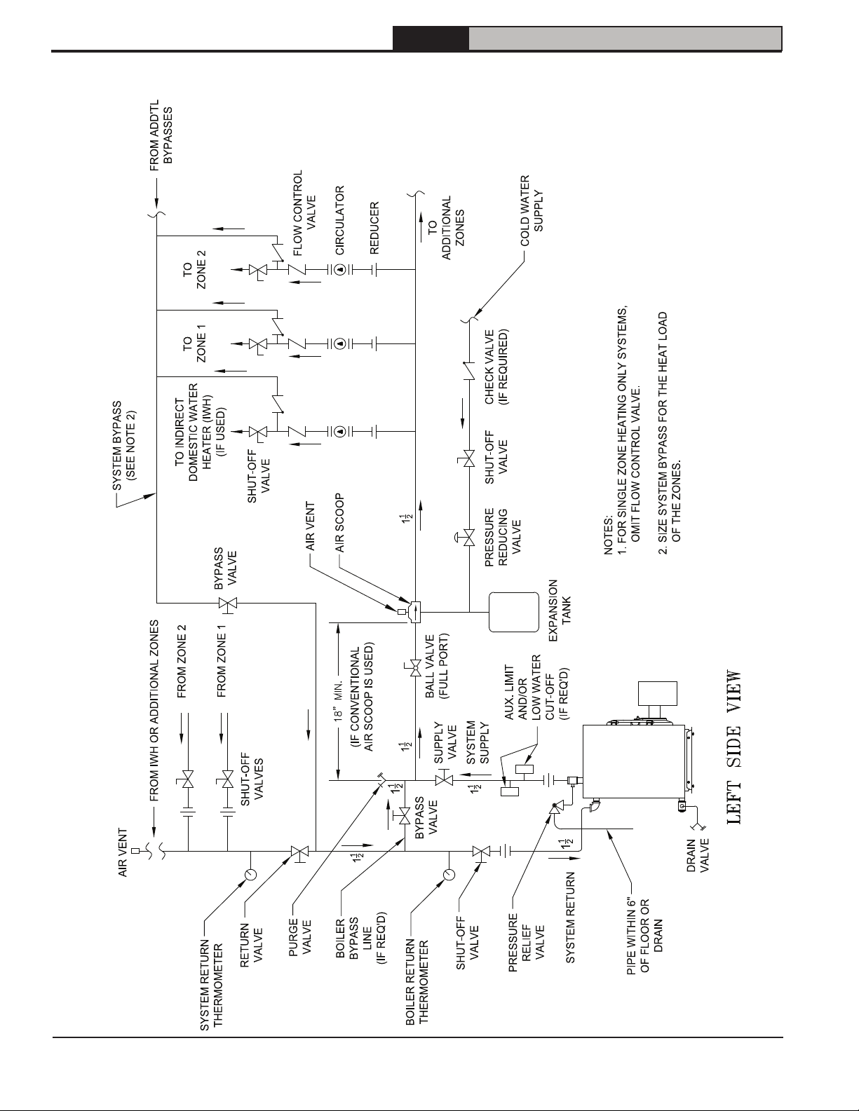
B. CONNECT SYSTEM SUPPLY AND RETURN
PIPING TO BOILER. See Figures 10A and
10B. Also, consult Residential Hydronic Heating
Installation and Design I=B=R Guide.
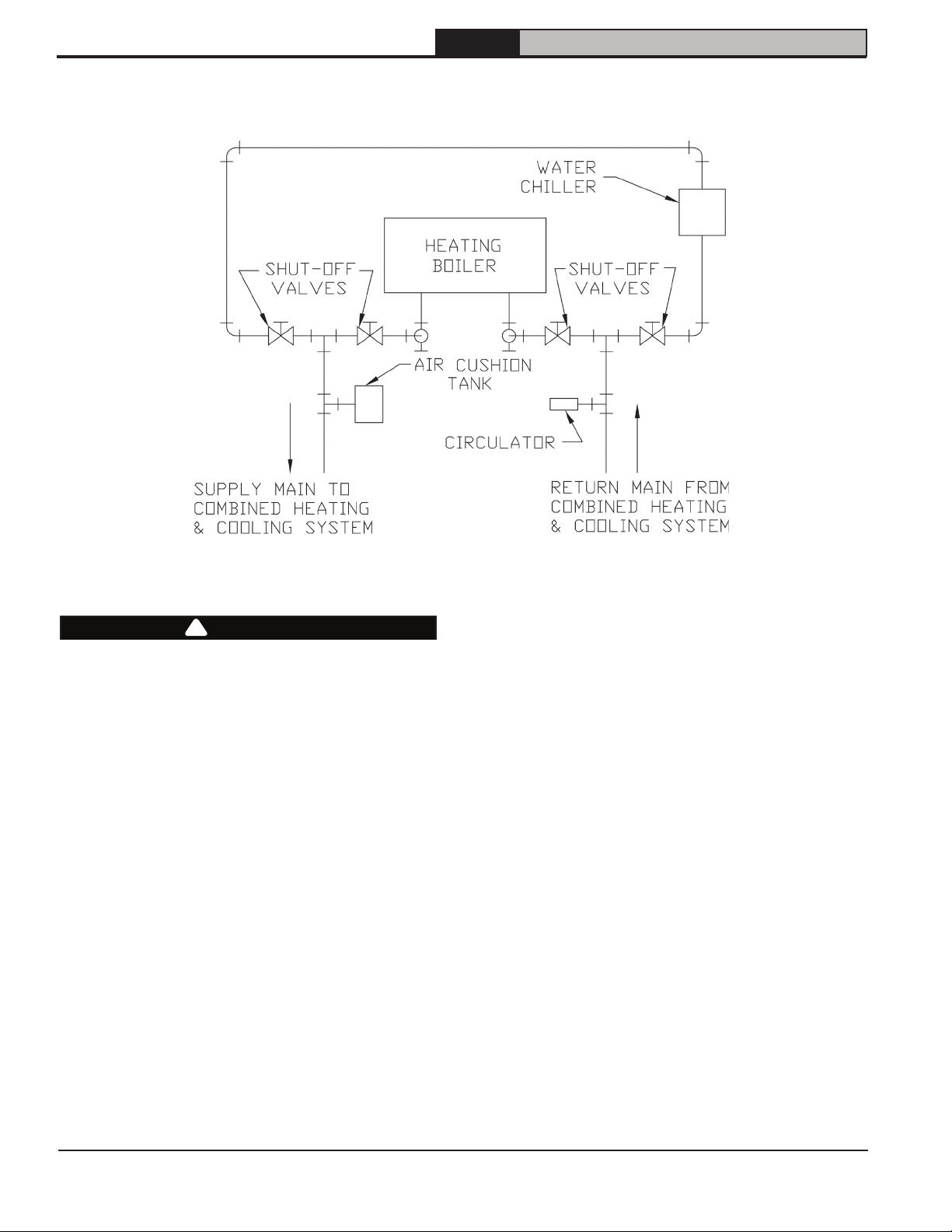
1. If this boiler is used in connection with refrigeration
systems, the boiler must be installed so that
the chilled medium is piped in parallel with the
heating boiler using appropriate valves to prevent
the chilled medium from entering the boiler. See
Figure 11. Also, consult Residential Hydronic
Heating Installation and Design I=B=R Guide.
2. If this boiler is connected to heating coils located
in air handling units where they may be exposed
to refrigerated air, the boiler piping must be
equipped with flow control valves to prevent
gravity circulation of boiler water during the
operation of the cooling system.
3. If an indirect water heater is used, priority zoning
can be used. Do not use priority zoning for HydroAir Systems. Refer to the Indirect Water Heater
Installation, Operating, and Service Instructions
for additional information.
4. The FORCE OIL is designed to withstand thermal
shock from return water temperatures as low as
100°F, but prolonged return temperatures of below
135°F can cause excessive flue gas condensation
and damage the boiler and/or venting system.
Use a boiler bypass if the boiler is to be operated
in a system which has a large volume or excessive
radiation where low boiler water temperatures
may be encountered (i.e. converted gravity
circulation system, etc.) The bypass should be
the same size as the supply and return lines
with valves located in the bypass and return line
as illustrated in Figures 10A and 10B in order to
regulate water flow for maintenance of higher
boiler water temperature.
106346-06 - 8/19
17
Page 18
4 Water Boiler Piping (continued)
FORCE
Installation, Operating & Service Manual
18
Figure 10A: Recommended Water Piping for Circulator Zoned Heating Systems - Supply Side Circulator
106346-06 - 8/19
Page 19
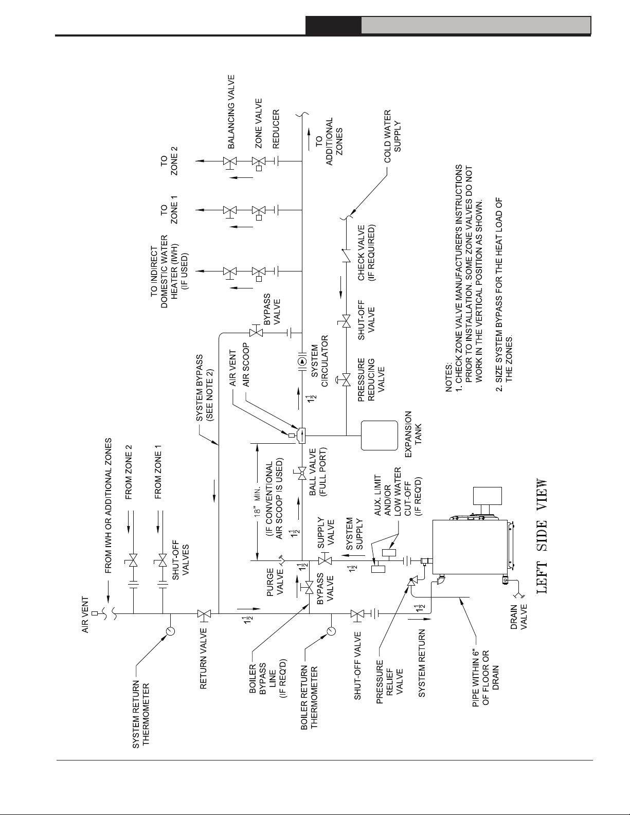
4 Water Boiler Piping (continued)
FORCE
Installation, Operating & Service Manual
106346-06 - 8/19
Figure 10B: Recommended Water Piping for Zone Valve Zoned Heating Systems - Supply Side Circulator
19
Page 20
4 Water Boiler Piping (continued)
FORCE
Installation, Operating & Service Manual
Figure 11: Recommended Piping for Combination Heating and Cooling (Refrigeration) System
WARNING
!
The use of a low water cut-off device, while
not required unless radiation level is below the
boiler, is highly recommended.
If a low water cut-off is required, it must be
mounted in the system piping above the boiler.
The minimum safe water level of a hot water boiler
is just above the highest water containing cavity of
the boiler; that is, a hot water boiler must be full of
water to operate safely.
5. If it is required to perform a long term
pressure test of the hydronic system, the
boiler should first be isolated from the system
to avoid a pressure loss due to the escape of
air trapped in the boiler.
To perform a long term pressure test including
the boiler, ALL trapped air must first be
removed from the boiler.
A loss of pressure during such a test, with no
visible water leakage, is an indication that the
boiler contained trapped air.
20
106346-06 - 8/19
Page 21
5 Indirect Water Heater Piping
FORCE
Installation, Operating & Service Manual
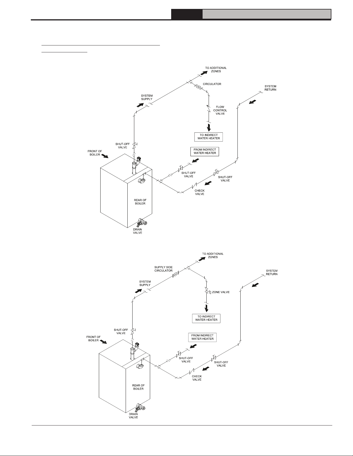
A. CONNECT INDIRECT DOMESTIC WATER
HEATER PIPING as shown in Figures 12A and
12B.
Also refer to Figures 10A and 10B.
Refer to instructions furnished with Indirect Water
Heater for additional information.
Figure 12A: Indirect Water Heater Piping w/Supply Side Circulator
on Circulator Zoned Heating System
Figure 12B: Indirect Water Heater Piping w/Supply Side Circulator on Zone Valve Zoned Heating System
106346-06 - 8/19
21
Page 22

FORCE
Installation, Operating & Service Manual
6 Natural Draft Venting (Chimney)
WARNING
!
• Vent this boiler according to these supplemental instructions. Failure to do so may cause products of
combustion to enter the home resulting in severe property damage, personal injury or death.
• Insufficient Combustion Air Supply may result in the production and release of deadly carbon monoxide (CO)
into the home which can cause severe personal injury or death.
• Improper venting may result in property damage and the release of flue gases which contain deadly carbon
monoxide (CO) into the home, which can cause severe personal injury, death, or substantial property
damage.
• Inspect existing chimney and vent connector for obstructions and deterioration before installing boiler.
Failure to clean or replace perforated pipe or chimney liner will cause severe injury or death.
• Do not de-rate the appliance. Failure to fire the boiler at it's designed input may cause excessive
condensation upon the interior walls of the chimney. In addition, the lower input may not create enough draft
to adequately evacuate the by-products of combustion.
A. CHIMNEY VENTING
1. Chimney venting is an important part of a safe
and efficient oil fired appliance system. Contact
your local fire and building officials on specific
requirements for restrictions and the installation
of fuel oil burning equipment. In addition,
consult with a professional knowledgeable on
the requirements of NFPA 31 – Standard for
the Installation of Oil-Burning Equipment and
NFPA 211 - Standard for Chimneys, Fireplaces,
Vents, and Solid Fuel-Burning Appliances for
installations in the United States. Installations
in Canada must be reviewed with a professional
knowledgeable on the requirements of CSA B139
– Installation Code for Oil-burning Equipment.
2. The safe venting of oil fired boilers is dependant
on many factors. Some of these factors include:
a. sufficient draft during the entire heating season
to allow for the safe discharge of combustion
by-products and;
b. suitable corrosion protection in the event of
condensing flue gases. Only a trained and
qualified contractor may install this product.
3. The FORCE OIL shall be vented into any of the
following:
a. Masonry or metal chimney. Build and install
in accordance with local buildings codes;
or local authority having jurisdiction; or
“Standards for Chimney, Fireplace, Vents,
and Solid Fuel Burning Appliances”, ANSI/
NFPA 211 and/or National Building Code of
Canada. Masonry chimney must be lined
with listed chimney system. Listed clay
flue lined masonry chimneys meet venting
requirements.
• External chimneys are more susceptible
to flue gas condensation due to colder
outside air temperatures. To prevent
corrosion due to flue gas condensation,
use a listed corrosion-resistant metal
liner in chimney.
22
• Oversized chimneys are more
susceptible to flue gas condensation.
To reduce the likelihood of flue gas
condensation and ensure proper draft,
use a properly sized listed metal liner in
oversized chimney.
4. Chimney Inspection – Prior to the installation
of any new or replacement fuel burning
equipment the chimney shall be inspected
by a qualified installer. The chimney shall
be inspected for integrity as well as for
proper draft and condensate control. Some
jurisdictions require the use of a liner when
changing fuel types. Some jurisdictions
require the use of a liner even when the same
fuel is used. At a minimum, the chimney
shall be examined by a qualified person in
accordance with the requirements of Chapter
11 of NFPA 211, Standard for Chimneys,
Fireplaces, Vents, and Solid Fuel-Burning
Appliances.
a. Loose Mortar – Loose mortar could be an
indication of a prior history of condensing flue
gases upon the inside walls of the chimney.
Colder climates are more susceptible to this
condition. Under no circumstances shall a
chimney of this condition be used until it meets
the requirements of NFPA 211 or CSA B139.
b. Unlined Chimney – Under no circumstances
shall a chimney constructed of brick only be
used. Only approved clay liners or listed
chimney lining systems shall be used as
specified in NFPA 31 or CSA B139.
c. Abandoned Openings – Openings through
the chimney wall that are no longer used
shall be sealed in accordance to NFPA 211.
Often abandoned openings are improperly
sealed and usually covered by a gypsum wall
covering.
d. Clean Chimney – Chimney shall be free of all
loose debris.
106346-06 - 8/19
Page 23

FORCE
6 Natural Draft Venting (Chimney) (continued)
FIRECLAY TILE LINED CHIMNEY
NOT LESS THAN 8" X 8" X 15'
Installation, Operating & Service Manual
NOTE:
ALL HORIZONTAL VENT PIPE
SHOULD SLOPE UPWARD NOT
LESS THAN ONE INCH IN
FOUR FEET.
DRAFT REGULATOR
DILUTION AIR
BOILER
(FRONT)
Figure 13: Recommended Vent Pipe Arrangement and Chimney Requirements
SEE
DETAIL 'A'
THIMBLE
SLOPE UP
VENT
SYSTEM
CLEANOUT
APPROX.
120°
AIR GAP
10 O'CLOCK
POSITION
6 O'CLOCK
POSITION
RECOMMENDED SCREW LOCATIONS
FOR CHIMNEY CONNECTORS
2 O'CLOCK
POSITION
106346-06 - 8/19
Figure 14: Proper and Improper Locations of Draft Regulator
23
Page 24

FORCE
6 Natural Draft Venting (Chimney) (continued)
Installation, Operating & Service Manual
5. Draft Regulator – a draft regulator (not supplied
with boiler) must be used with this appliance.
Refer to Figures 13 and 14.
B. CHIMNEY CONNECTOR
1. A chimney connector (vent pipe) is used to
connect the boiler to the base of the chimney.
The chimney connector should be kept as short
as possible. The horizontal length of the chimney
connector shall not be greater than 10 feet.
NOTE: Secure chimney connector to cast iron
smokebox collar with three (3) #10 x ½" self drilling
hex head TEK screws provided in miscellaneous
parts carton. Locate screws around perimeter
of connector as shown in Figure 15 and
approximately ½" in from edge. Use drill with
5/16" hex bit to drive screws through connector
and smokebox collar.
!
DANGER
The chimney and connector shall be inspected
annually for signs of debris and corrosion.
Loose mortar at the base of the chimney may be
a sign of condensate damage to the chimney.
A chimney professional shall be contacted
immediately to examine the damage and
recommend a solution. Long term operation
while in this condition may cause a venting
failure and force flue gases into the living
space. If the chimney is to be re-lined use the
recommendations in NFPA 31, Appendix E or
CSA B139.
C. DRAFT
1. The natural draft generated through a chimney is
dependent on several factors including, chimney
height, temperature of flue gases, cross section
area of chimney, chimney wall insulation value,
dilution air and total volume of flue gases, to
name a few. Make sure that the boiler has been
running for at least 5 minutes before measuring
the draft.
2. Minimum Draft at Breech (Canopy) – The draft
induced by a chimney must create at least a
pressure of 0 (zero) inches water column (“ w.c.)
at the pressure tapping on the canopy mounted
on rear of boiler (see Figure 15). The pressure
at the canopy cannot be positive since this could
create a condition that allows flue gas by-products
to escape from the draft regulator. A negative
pressure reading up to -.03 inches water column
is acceptable for proper operation. (See Tables
9 and 10 Burner Specifications at the rear of this
manual for more details)
3. Minimum Overfire Pressure – The overfire
pressure is another piece of information that
is often measured, however this should be
done for observation purposes only! The
breech pressure must be used to qualify
the draft condition. See Tables 9 and 10 for
more details as a guide. Actual draft and
temperature measurements may be different
then those values in the table.
2. Vent Connector shall be any of the following
and of the same size as the outlet of boiler.
a. Type L or a factory built chimney material
that complies with the Type HT requirements
of ANSI/UL 103. Install in accordance with
listing and manufacturer’s instructions.
b. Steel pipe having resistance to corrosion
and heat with a minimum wall thickness of
24 Gauge (0.024”).
DANGER
!
Any signs of condensate seepage at the base
of the chimney shall be inspected immediately.
The discoloration may be a sign of chimney
damage and must be remedied immediately.
24
Figure 15: Smokebox Pressure Tapping for
Checking Draft at Breech
106346-06 - 8/19
Page 25

FORCE
6 Natural Draft Venting (Chimney) (continued)
Installation, Operating & Service Manual
D. STACK TEMPERATURE
1. The temperature of the flue gases has a significant
effect on the amount of draft created in a vertical
chimney as well as the propensity to create
condensate. The higher the stack temperature,
the greater the amount of draft that can be
generated. A lower stack temperature not only
reduces the amount of draft that can be created
but it also increases the possibility that the flue
gases could condense in the chimney connector
or stack.
2. NFPA 31 and CSA B139 have information to
help the installer make an appropriate choice
of venting materials. In some cases a chimney
may have to be lined to create sufficient draft. In
other cases, the chimney may have to be lined
to prevent the corrosion of a masonry chimney.
Consult with a chimney specialist knowledgeable
on the requirements for chimney requirements in
your area.
CAUTION
!
Any doubt on the condition of a chimney
or it’s ability to prevent the generation and
accumulation of flue gas condensate, must be
relined according to NFPA 31 (United States) or
CSA B139 (Canada).
!
CAUTION
Use the chimney venting tables as a guide. It
is highly recommended that any borderline
application should result in the relining of
the chimney with a suitable liner that creates
sufficient draft and to protect against corrosion
caused by flue gas condensate.
3. Baffles – The efficiency of the boiler is based on the
insertion of flue baffles supplied with your product.
Under no circumstances are other baffles to be
used on this product. Refer to Section III, Item
F, Paragraph 6 for baffle installation. If there is
any doubt on the application of this boiler on the
intended chimney, consult with your local code
officials. At a minimum, remove the baffles to
increase the stack temperature. See Tables 9 and
10 for temperature differential (∆T) with baffles
IN and OUT. In addition, the lower the CO
the higher the stack temperature.
WARNING
!
Remove the baffles if there are any signs of
condensation in the chimney or chimney
connector. Consult with your local chimney
professional for recommendations.
E. MINIMUM CLEARANCES
See Figure 2A for details regarding clearances to
combustibles for the boiler.
level
2
106346-06 - 8/19
25
Page 26

7 Direct Venting / Air Intake Piping
FORCE
Installation, Operating & Service Manual
A. GENERAL GUIDELINES
1. Direct Vent system must be installed in accordance
with these instructions and applicable provisions
of local building codes. Contact your local fire
and building officials on specific requirements
for restrictions and the installation of fuel oil
burning equipment. In addition, for boiler
installation in United States, consult with a
professional knowledgeable on requirements
of NFPA 31- Standard for the Installation of Oil-
Burning Equipment and NFPA 211 Standard
for Chimney, Fireplaces, Vents and Solid FuelBurning Appliances, latest editions.
2. In the Direct Vent configuration, all air for
combustion is supplied directly to the burner
from outdoors, and, flue gases are vented directly
outdoors (thru wall), via Direct Vent System
(FDVS), which is a non-positive pressure vent
system termination for oil-fired appliances, that
provides an outlet for products of combustion,
and, an intake for combustion air in a single
concentric terminal.
3. Direct Vent Hood Assembly minimum clearance
to combustible material is 0".
4. Maximum wall thickness that FDVS vent
termination may be installed through is 12".
WARNING
!
This venting system must be installed by a
qualified installer (an individual who has been
properly trained) or a licensed installer.
DO NOT locate vent termination where exposed
to prevailing wind. Moisture and ice may form
on surfaces around vent termination. To prevent
deterioration, surface must be in good repair
(sealed, painted etc.).
DO NOT locate vent termination where
petroleum distillates, CFC's, detergents, volatile
vapors or any other chemicals are present.
Severe boiler corrosion and failure will result.
DO NOT locate vent termination under a deck.
5. Locate the vent terminal so vent pipe is short
and direct, and, at the place on exterior wall
that complies with the minimum distances as
specified in Figure 16 and listed as follows. The
vent termination must be located (as measured
to the bottom of vent terminal):
a. Not less than 12" above finished grade or
expected snow accumulation line whichever
is greater.
b. Not less than 3 ft above any forced air inlet
located within 10 ft.
c. Not less than 4 ft from any door, window or
gravity air inlet.
26
Figure 16: Vent Terminal Location
106346-06 - 8/19
Page 27

FORCE
7 Direct Venting / Air Intake Piping (continued)
Installation, Operating & Service Manual
d. Not less than 7 ft above grade when located
above public walkway.
e. Not less than 3 ft (as measured to side of
vent termination) from an inside corner of an
L-shaped structure.
f. Not less than 1 ft from the nearest surface of
the terminal to a roof soffit.
g. Not directly above, or, not less than 6 ft
horizontally from an oil tank vent or gas meter.
h. Not less than 2 ft from nearest surface of
terminal to an adjacent building.
B. INSTALLATION OF THE VENT HOOD TERMINAL
(see Figures 17, 18, 19 and 20)
1. Inspect Direct Vent Conversion Kit Carton for
damage. DO NOT install if any damage is evident.
2. Direct Vent Conversion Kit Carton includes:
• Direct Vent Hood Assembly (consists of Vent
Hood Body and Combustion Air Tee) – 1 pc
• Backing Plate – 1 pc
• Vacuum Relief Valve VRV-4 – 1 pc
• Hardware Bag (includes high temperature
sealant, fasteners and inner pipe clamps) – 1
pc
• Appliance Adapter – 1 pc
• Appliance Clamp Halves – 2 pcs
• Cover Sleeve Assemblies – 2 pcs
• Cover Ring Assemblies – 2 pcs
3. Remove vent system components from carton
and set aside.
4. Separate the vent hood tee from the vent hood
body and set aside for later use.
5. After determining the location of the venting
system termination, cut the square hole in the
wall sized according to “L” dimension in Table
5, see Figure 17.
6. Wood or vinyl siding should be cut, so that vent
hood base plate mounts directly on the wallboard
to provide stable support. If siding thickness
exceeds ½”, use a spacer bar or board behind
the vent hood mounting (base) plate. See Figure
18.
a. Seal the backside of the vent hood base plate
around the outer pipe of the vent hood with a
bead of high-temperature silicone sealant.
b. Mount the vent hood body from outside,
through the wall, keeping the outer pipe
centered in the hole.
c. Fasten the vent hood body to the outside wall
with appropriate fasteners (installer provided).
Table 5: Wall Cutout Dimensions
Boiler Model
FORCEOL140-E
FORCEOL182-E
Figure 17: Wall Cutout Dimensions
Figure 18: Vent Hood Body Installation
d. Seal the edges of the vent hood base plate
to the wall with a high-temperature silicone
sealant.
e. While inside, position the backing plate over
the outer pipe and fasten to inside wall with
appropriate fasteners (installer provided).
Direct Vent Conversion
Kit Part No.
106401-01 8¼
"L" Dimension
(Inch)
106346-06 - 8/19
27
Page 28

FORCE
7 Direct Venting / Air Intake Piping (continued)
Figure 19: Combustion Air Tee
Assembly Installation
C. INSTALLATION OF VENT HOOD TEE
1. Assemble the vent hood tee body to the vent hood
outer pipe, and, rotate the tee, so air intake inlet
collar is in the desired position. See Figure 19.
2. Attach the vent hood tee body to the vent hood
outer pipe with at least three sheet metal screws
(installer provided).
NOTE: The tee may be rotated into any position
so that the collar is in a convenient orientation.
3. After completing assembly of the flexible double
wall insulated vent pipe to the vent termination
inner pipe (see Figure 20 and the following Steps),
apply the supplied high temperature sealant to
seal around the inner pipe protrusion thru the vent
tee cover pan, around the joint between the vent
tee collar and the vent tee body, and, seal or tape
the joint between the vent termination outer pipe
and the vent tee body.
Installation, Operating & Service Manual
D. INSTALLING THE FLEX OIL VENT PIPE
FROM THE VENT TERMINATION TO THE
BOILER FLUE OUTLET
1. The venting system (vent pipe and all connectors)
shall be installed in accordance with the
applicable provisions of any local codes, and, in
United States, requirements of NFPA 31- Standard
for the Installation of Oil-Burning Equipment and
NFPA 211 Standard for Chimney, Fireplaces,
Vents and Solid Fuel-Burning Appliances, latest
editions.
2. A vent pipe connector, designed for positive
pressure venting, shall be supported for the
design and weight of material employed, to
maintain clearances, prevent physical damage
and separation of joints. All joints MUST BE
sealed, for positive vent pressure, to prevent flue
gas leakage into the structure.
3. Support the vent pipe at intervals no greater than
three (3) feet apart using perforated metal strap
or other non-combustible supports.
4. Allow sealant to cure at least one hour before
firing boiler.
5. Route the vent pipe from the vent termination to
the boiler using the minimum number of bends
possible. The last horizontal section of the vent
pipe should have a slight downward slope from
the boiler to the vent termination. For clearances
to combustible materials refer to Figure 2B.
6. Maximum length of flexible oil vent pipe is 20 ft.
The vent pipe is also available pre-cut in 10 ft.
7. Verify that flex vent pipe diameter and vent
termination inner pipe diameter correspond to a
particular direct vent configuration FORCE OIL
boiler model (see Table 6).
28
Figure 20: FDVS Component Breakdown
106346-06 - 8/19
Page 29

FORCE
7 Direct Venting / Air Intake Piping (continued)
Table 6: Flex Vent / Vent Termination Pipe Diameters
Installation, Operating & Service Manual
Boiler Model
FORCEOL140-E
FORCEOL182-E
NOTE: * The model specific Direct Vent (FDVS) Kit Cartons contain adapters (reducers) (see Table 6) to connect boiler flue outlet
collar to vent pipe.
Boiler Flue Outlet
Collar OD (Inch)
6 5 6 to 5
Vent Hood
Inner Pipe
Diameter (Inch)
Flex Oil Vent Pipe
Inner Pipe Diameter
(Inch)
* Flue Outlet Collar to
Vent Pipe Adapter (Inch)
Figure 21: Appliance Adapter Installation
E. CONNECTING APPLIANCE ADAPTER TO
BOILER FLUE OUTLET COLLAR
(See Figure 21) reimburse
1. Apply a bead of supplied high temperature sealant
to boiler flue outlet collar approximately 1" from
collar end.
2. Remove any oil and grease from inside of supplied
Appliance (Boiler Flue Outlet) Adapter, and, apply
a bead of high temperature sealant to inside of
the adapter, ½" from end.
3. With twisting motion, assemble the appliance
adapter onto boiler flue outlet collar.
4. Using a mallet and a block of wood, carefully
tap the adapter onto the outlet collar. Insure no
damage is done to the adapter and the flue outlet
collar.
5. Assemble supplied adapter clamp halves with
5/16-18 bolts and square nuts; install the adapter
clamp onto the appliance adapter and tighten
securely.
6. If required, install anchoring screws (installer
provided) thru four holes in the clamp into the
flue outlet collar.
7. Apply sealant around the adapter end mated to
the flue outlet collar.
8. Install supplied 3/8” sampling port plug screw
hand tight into the adapter sampling port.
9. After initial boiler start-up and burner
testing/adjustment are completed, apply high
temperature sealant under the head of sampling
port plug screw, and, install the screw in the
sampling port tightening securely.
F. CONNECTING FLEX OIL VENT PIPE TO
APPLIANCE ADAPTER AND DIRECT VENT
TERMINATION
1. Flexible double wall oil vent pipe is available
pre-cut in 5 ft and 20 ft length. If necessary, the
vent pipe may be cut to required length with a
hacksaw or cutoff saw.
CAUTION
!
Use safety glasses and other appropriated
safety gear when cutting the vent pipe.
2. The double wall flexible vent pipe consists of the
smaller inner corrugated stainless steel pipe and
larger corrugated aluminum pipe, separated by
fiberglass insulation layer.
106346-06 - 8/19
29
Page 30

FORCE
7 Direct Venting / Air Intake Piping (continued)
Figure 22: Vent Pipe Assembly to Vent Termination
Inner Pipe and Appliance Adapter
CAUTION
The inner and outer pipe ends may have sharp
burrs. Use gloves, while handling, compressing
or expanding the vent pipe.
3. Pull outer vent pipe back 1” to 2” from end of
inner vent pipe and remove insulation; firstly,
at vent pipe end to be connected to the vent
termination; secondly, at vent pipe end to
be connected to the appliance adapter. See
Figure 22.
4. Install supplied Cover Sleeve Assembly onto
each end of outer vent pipe, and, move the
assembly a few inches back from the end;
firstly, at vent pipe side to be connected to the
vent termination; secondly, at vent pipe side
to be connected to the appliance (boiler outlet
collar) adapter. See Figure 22.
5. Slide supplied Cover Rings; firstly, over stop
bead on vent termination inner pipe; secondly,
over stop bead on appliance adapter. See
Figure 22.
6. Remove any oil and grease from the end of
vent termination inner pipe, and, from the end
of the appliance adapter.
Installation, Operating & Service Manual
7. Apply sealant; firstly, between the stop bead
and retainer bead at the end of the vent
termination inner pipe; secondly, between the
stop bead and retainer bead at the end of the
appliance adapter. See Figure 23.
8. Assemble supplied inner pipe clamp halves
with 1/4-20 bolts and square nuts; position the
inner pipe clamps ¼” from the end of inner
vent pipe, on vent pipe opposite ends.
9. Remove any oil and grease from inside of each
end of the inner vent pipe.
10. Apply a thick bead of sealant to inside of each
end of the inner vent pipe, ½” from pipe end,
working the sealant into the inner vent pipe
corrugations. See Figure 23.
11. Firstly, push one end of the inner vent pipe onto
the vent termination inner pipe, all the way up
to the stop bead. Secondly, push the opposite
end of the inner vent pipe onto the appliance
adapter, all the way up to the stop bead.
12. Tighten the inner pipe clamp bolts at both vent
pipe ends, until clamp halves are within 1/8”
apart. See Figure 24.
13. Starting with vent termination end, slide the
cover sleeve assembly and the cover ring
together to engage the ring in the groove of the
sleeve, then, tighten the built-in cover sleeve
clamp. Repeat above steps at the boiler end.
See Figure 24.
14. If the appliance collar is within less than 18"
of combustible material, wrap minimum 1-1/2"
thick fiberglass insulation (installer provided).
15. To maintain vent pipe 1" clearance to
combustible material, wrap minimum 1-1/2"
thick fiberglass insulation (installer provided)
around the exposed portion of the vent
termination inner pipe and secure with
adhesive-backed aluminum foil tape (installer
provided).
30
Figure 23: Vent Pipe Ends, Vent Termination and Appliance Adapter Sealing
106346-06 - 8/19
Page 31

FORCE
7 Direct Venting / Air Intake Piping (continued)
Figure 24: Vent Pipe Assembly to Vent Termination
Inner Pipe & Appliance Adapter
Installation, Operating & Service Manual
WARNING
!
DO NOT reduce size of air intake pipe.
3. Remove burner from carton. Secure burner to
boiler with mounting hardware included with
burner swing door. See Figure 26.
4. Remove knockout for 4" vent pipe collar from
burner cover. See Figure 26.
5. Start at burner and work towards Direct Vent
termination air intake.
6. Procure a 2-ft section of 4" diameter galvanized
single wall vent pipe, cut off the crimped pipe
end below stop bead.
7. Insert one end of the vent pipe thru the outside
air duct bracket opening and firmly push onto
the outside air adapter collar.
8. Secure the pipe to collar with at least (3)
sheet metal screws (installer provided) evenly
spaced around the collar.
NOTICE: It is essential to ensure reliable
operation that combustion air joints are air tight
and that VRV is located as close to the burner as
possible.
G. INSTALLING THE AIR INTAKE PIPING FROM
DIRECT VENT TERMINATION TO BURNER
OUTSIDE AIR ADAPTER
1. Use 4" diameter galvanized single wall vent pipe
and fittings, available at most heating distributors,
to connect burner outside air adapter to Direct
Vent Termination air intake collar. See Figure 25.
2. Maximum air intake pipe length is 40 equivalent
feet.
NOTE: 90° elbow is equivalent to 5 linear feet.
9. Install supplied vacuum relief valve tee assembly,
crimped end down, into the opposite end of vent
pipe.
10. Secure the tee to the pipe with at least (3) sheet
metal screws (installer provided) evenly spaced.
11. Remove the vacuum relief valve gate assembly
from the tee.
106346-06 - 8/19
Figure 25: Install Air Intake Piping and Vacuum Relief Valve
31
Page 32

FORCE
7 Direct Venting / Air Intake Piping (continued)
Installation, Operating & Service Manual
12. Assemble the vacuum relief valve balance weight
onto the gate. Refer to the vacuum relief valve
manufacturer’s instructions for details.
13. Mount the assembled vacuum relief valve gate
with balance weight into the tee and fasten with
a screw and nut in collar tabs. To insure proper
operation, the gate must be level across the pivot
point and plumb. Refer to the vacuum relief valve
manufacturer’s instructions for details.
14. Install remainder of air intake piping to Direct
Vent Termination air intake collar, securing
each joint with at least (3) sheet metal screws
(installer provided) evenly spaced.
15. Maintain ¼” per foot slope in horizontal run to
air intake of Direct Vent Termination.
16. Support the air intake piping, as required, using
perforated metal strap or other supports.
17. Refer to Burner Manufacturer's Manual for
addition information.
32
Figure 26: Oil Burner Installation (NX Beckett shown)
106346-06 - 8/19
Page 33

FORCE
Installation, Operating & Service Manual
8 Electrical
!
DANGER
Positively assure all electrical connections are unpowered before attempting installation or service of
electrical components or connections of the boiler or building. Lock out all electrical boxes with padlock
once power is turned off.
WARNING
!
• Failure to properly wire electrical connections to the boiler may result in serious physical harm.
• Electrical power may be from more than one source. Make sure all power is off before attempting any
electrical work.
• Each boiler must be protected with a properly sized fused disconnect.
• Never jump out or make inoperative any safety or operating controls.
A. GENERAL
1. Install wiring and electrically ground boiler in
accordance with requirements of the authority
having jurisdiction, or in absence of such
requirements the National Electrical Code,
ANSI/NFPA 70.
2. Refer to National Electric Code or Local
Electric Codes for proper size and type of wire
required. Follow Code.
3. A separate electrical circuit must be run from
the main electrical service with an over-current
device/disconnect in the circuit. A service
switch is recommended and may be required
by some local jurisdictions.
4. Use anti-short bushings on all wiring passing
through boiler jacket, junction boxes and/or
control boxes.
5. Use armored cable (BX) over all exposed line
voltage wiring.
6. If an indirect domestic water heater is used,
use priority zoning. Do not use priority zoning
for Hydro-Air Systems.
7. Wiring should conform to Figures 27, 28, and
29.
B. INSTALL A ROOM THERMOSTAT on an
inside wall about four feet above floor. Never
install thermostat on an outside wall or where
it will be influenced by drafts, hot or cold water
pipes, lighting fixtures, television, rays of the sun
or near a fireplace. Keep large furniture away from
thermostat so there will be free movement of room
air around this control.
Heat Anticipator in Thermostat should be set to
match the requirements of the control to which
it is connected. See Figures 27 and 28 for
desired system and heat anticipator setting. If
system tends to overheat above the thermostat's
temperature setting, reduce heat anticipator
setting by .1 or .2 amps. If system tends to short
cycle without reaching desired room temperature,
increase heat anticipator setting by .1 or .2 amps.
106346-06 - 8/19
33
Page 34

8 Electrical (continued)
FORCE
Installation, Operating & Service Manual
34
Figure 27: Schematic Wiring Diagram HydroStat 3250 Control with Beckett AFG Series Burners
106346-06 - 8/19
Page 35

8 Electrical (continued)
FORCE
Installation, Operating & Service Manual
106346-06 - 8/19
Figure 28: Schematic Wiring Diagram HydroStat Control to Beckett NX Burners
35
Page 36

8 Electrical (continued)
NOTE: APPLY THIS BURNER
SCHEMATIC TO APPROPRIATE
STEAM OR WATER BOILER
CONTROL SCHEMATIC, REFER
TO Figure 27
FORCE
Installation, Operating & Service Manual
NOTE: APPLY THIS BURNER
SCHEMATIC TO APPROPRIATE
STEAM OR WATER BOILER
CONTROL SCHEMATIC, REFER
TO Figure 28
36
Figure 29: Schematic Wiring Diagrams
106346-06 - 8/19
Page 37

9 Oil Piping
FORCE
Installation, Operating & Service Manual
A. GENERAL
1. Use flexible oil line(s) so the burner swing door
can be opened without disconnecting the oil
supply piping.
2. A supply line fuel oil filter is recommended as a
minimum for all firing rates but a pleated paper
fuel oil filter is recommended for the firing rates
below 1.0 GPH to prevent nozzle fouling.
3. Use Flared fittings only. Cast iron fittings
cannot be used.
NOTICE: Do not use compression fittings.
Oil piping must be absolutely airtight or leaks or
loss of prime may result. Bleed line and fuel unit
completely.
Refer to your local jurisdictions regarding
any special considerations for fuel supply
requirements. In addition, refer to NFPA 31,
Standard for the Installation of Oil-Burning
Equipment.
4. Use of a high efficiency micron filter (Garber or
equivalent) in addition to a conventional filter is
highly recommended.
5. Piping used to connect the oil burner to the oil
supply tank shall not be smaller than 3/8" iron
pipe or 3/8" OD copper tubing. Copper tubing
shall have a .032" minimum wall thickness.
WARNING
!
Under no circumstances can copper with sweat
style connectors be used.
NOTICE: Some jurisdictions require the use of a
fusible shutoff valve at the tank and/or the burner.
In addition, some jurisdictions require the use of a
fusible electrical interlock with the burner circuit.
Check your local Codes for special requirements.
B. SINGLE PIPE OIL LINES
1. Standard burners are provided with singlestage 3450 RPM fuel units with the bypass
plug removed for single-pipe installations.
2. The single-stage fuel unit may be installed
single-pipe with gravity feed or lift. Maximum
allowable lift is 8 feet. See Figure 30.
3. Fuel Oil Line Deaerator – On many occasions
a leaky oil delivery line can introduce air
into the fuel oil supply system. This often
creates a rough starting condition and can
create a burner lockout state. In addition to
fixing the leak, a fuel line deaerator can be
installed to eliminate air. The single line from
the fuel tank is connected to the deaerator.
The burner pump must be connected to the
deaerator as a two pipe system. Follow the
oil pump manufacturer’s recommendations for
conversion to a two pipe system.
106346-06 - 8/19
Figure 30: Single Pipe Oil Line
37
Page 38

9 Oil Piping (continued)
FORCE
Installation, Operating & Service Manual
C. TWO PIPE OIL LINES
1. For two piped systems, where more lift
is required, the two-stage fuel unit is
recommended. Table 7 (two-stage) and Table
8 (single-stage) show allowable lift and lengths
of 3/8 inch and 1/2 inch OD tubing for both
suction and return lines. Refer to Figure 31.
2. Follow the oil pump manufacturer’s
recommendations on the proper connections
for a two pipe system. Some manufacturers
require the insertion of a bypass plug.
Table 7: Two-Stage Units (3450 RPM) -
Two Pipe Systems
Maximum Length of Tubing
Lift "H"
"H" + "R" (See Figure)
3/8" OD
Tubing (3 GPH)
0' 93' 100'
2' 85' 100'
4' 77' 100'
6' 69' 100'
8' 69' 100'
10 52' 100'
12' 44' 100'
14' 36' 100'
16' 27' 100'
18' --- 76'
Tubing (3 GPH)
1/2" OD
3. Under no circumstances is a manual shutoff
valve to be located on the return line of a two
pipe system. Accidental closure of the return
line will rupture the oil pump seals.
Table 8: Single-Stage Units (3450 RPM) -
Two Pipe Systems
Maximum Length of Tubing
Lift "H"
0' 84' 100'
1' 78' 100'
2' 73' 100'
3' 68' 100'
4' 63' 100'
5' 57' 100'
6' 52' 100'
7' 47' 100'
8' 42' 100'
9' 36' 100'
10' 31' 76'
11' 26' 100'
12' 21' 83'
13' --- 62'
14' --- 41'
"H" + "R" (See Figure)
3/8" OD
Tubing (3 GPH)
1/2" OD
Tubing (3 GPH)
38
Figure 31: Two Pipe Oil Lines
106346-06 - 8/19
Page 39

FORCE
Installation, Operating & Service Manual
10 System Start-Up
WARNING
!
All boilers equipped with burner swing doors have a potential hazard which can cause severe property
damage, personal injury or loss of life if ignored. Before opening swing door, turn off service switch to boiler
to prevent accidental firing of burner outside the combustion chamber. Be sure to tighten swing door fastener
completely when service is completed. In addition, the burner power cord will have to be disconnected from
the receptacle in the front jacket.
A. ALWAYS INSPECT INSTALLATION
BEFORE STARTING BURNER.
1. Verify that the venting, water piping, oil piping,
and electrical system are installed properly.
Refer to Installation Instructions contained in
this manual.
2. Confirm all electrical, water and oil supplies
are turned off at the source and that the vent is
clear from obstructions.
WARNING
!
Completely read, understand and follow all
instructions in this manual before attempting
start up.
B. FILL HEATING SYSTEM WITH WATER.
NOTICE: It is important to properly remove the
oil and dirt from the system. Failure to clean the
system can result in clogged air vents, circulator
damage and seized zone valves.
CLEAN HEATING SYSTEM if boiler water is
dirty.
Refer to Maintenance and Service Instructions
Section of this manual for proper cleaning
instructions for water boilers.
1. HOT WATER BOILERS. Fill entire heating
system with water and vent air from system.
Use the following procedure on a series loop
or multi-zoned system installed as per Figures
10A and 10B, to remove air from system when
filling:
a. Close full port ball valve in boiler system
piping.
b. Isolate all zones by closing zone valves or
shut-off valves in supply and return of each
zone(s).
c. Attach a hose to vertical purge valve in
boiler system supply piping up stream from
the full port ball valve.
(NOTE - Terminate hose in five gallon
bucket at a suitable floor drain or outdoor
area).
d. Starting with one zone at a time, open zone
valve or shut-off valve in boiler supply and
return piping.
e. Open purge valve.
f. Open shut-off valve in cold water supply
piping located between the air scoop and
expansion tank.
g. Allow water to overflow from bucket until
discharge from hose is bubble free for 30
seconds.
h. When zone valve is completely purged of
air, close zone valve or shut-off valve. Open
zone valve to the next zone to be purged.
Repeat this step until all zones have been
purged. At completion, open all zone
valves.
i. Close purge valve, continue filling the
system until the pressure gauge reads
12 psi. Close shut-off valve in cold water
supply piping.
WARNING
!
The maximum operating pressure of this boiler
is posted on the ASME Data Label located
on the top of the boiler. Never exceed this
pressure. Do not plug relief valve.
NOTICE: If make-up water line is equipped with
pressure reducing valve, system will automatically
fill to 12 psi. Follow fill valve manufacturer's
instructions.
j. Open full port ball valve in boiler system
piping.
k. Remove hose from purge valve.
l. Confirm that the boiler and system have no
water leaks.
m. It may be necessary to clean the air vent
assembly after a few days of operation.
C. CHECK CONTROLS, WIRING AND
BURNER to be sure that all connections are tight
and burner is rigid, that all electrical connections
have been completed and fuses installed, and
that oil tank is filled and oil lines have been tested.
106346-06 - 8/19
39
Page 40

10 System Start-Up (continued)
FORCE
Installation, Operating & Service Manual
D. ADJUST CONTROL SETTINGS with burner
service switch turned “ON”.
1. SET ROOM THERMOSTAT about 10°F below
room temperature.
2. PRESS RED RESET BUTTON on burner
primary control, hold for ten (10) seconds and
release to reset the control.
3. CHECKOUT
Put the system into operation and observe
at least one complete cycle to make sure
that the controller operates properly. See
Troubleshooting Section to use LED to assist in
determining system operation.
E. CHECK / ADJUST OIL BURNER BEFORE
STARTING.
Natural Vent Applications:
1. Beckett AFG Burners
a. Verify nozzle size, head size, gun setting,
and positioning of electrodes. This
information is shown in Figure 32, and
Beckett AFG Burner Specifications, Table 9.
b. Inspect Beckett head setting on left side
of burner housing by insuring the blue line
MD(V1) or the line on the label MB(L1)
are aligned, readjust if necessary. Refer
to Figure 32 and Table 9 at the end of this
manual.
c. Check burner air band and air shutter
settings. Readjust if necessary, see Beckett
AFG Burner Specifications, Table 9 at the
end of this manual.
d. OPEN ALL SHUT-OFF VALVES in the oil
supply line to the burner.
e. ATTACH A PLASTIC HOSE TO FUEL PUMP
VENT/BLEED FITTING and place the other
hose end into an empty container to catch
the oil.
f. SLIGHTLY OPEN FLAME OBSERVATION
PORT COVER on burner swing door,
enough to insert draft gauge probe later.
Direct Vent Applications:
2. Beckett NX Burners
a. Verify nozzle size, gun setting and
positioning of electrodes. See Figures
34 and 36 and Beckett NX Burner
Specifications, Table 10 at the end of this
manual.
b. Remove burner cover by loosening the four
thumb screws and set aside.
c. Disconnect the copper oil connector tube
from nozzle line.
d. Loosen the two screws securing igniter-
retaining clips and rotate both clips to
release the igniter baseplate. The igniter
should pop-up and would be supported by
the prop spring.
e. Loosen the two screws securing the rear
door, then swing to the right and down.
f. Loosen splined nut.
g. Lift up the igniter baseplate and
simultaneously remove nozzle line assembly
from burner by drawing it straight back out
the rear door opening. Be careful not to
damage the electrodes or insulators while
handling.
h. Check electrodes to comply with
dimensions shown in Figure 33. For
adjustment, loosen the electrode clamp
screw and slide/rotate electrodes as
needed. Securely re-tighten the clamp
screw when finished.
i. Check retention head alignment. Cad
cell sighting holes in the throttle cup and
retention head must line up, so the cad
cell can see the flame. Make sure that, the
“stamped key” in the retention head collar
lines up with the “keyway” in the nozzle
adapter, when mounting the retention head.
See Figure 34.
j. To re-install the nozzle line assembly,
reverse procedure outlined in steps f thru b.
k. Upon reinstallation of the nozzle line
assembly, check that head/air plate setting
number pointer lines up with a number on
the scale, which matches a value shown
in Table 10 for a particular boiler/burner
model.
The zero calibration has been factory set;
the upper left acorn nut locks retention head
at “0” position. If the zero calibration has to
be reset, follow the adjustment procedure,
outlined at “Prepare Burner & Site” section
of Beckett Model NX Oil Burner Instruction
Manual, Form Number 610BNX. Make
sure the retention head is securely against
the stops in the retention ring, when the
adjustment plate pointer is at “0”.
l. The rear door must be kept tightly closed
upon reinstallation of the nozzle line
assembly.
40
106346-06 - 8/19
Page 41

10 System Start-Up (continued)
FORCE
Installation, Operating & Service Manual
106346-06 - 8/19
Figure 32: "L1" and "V1" Head Electrode Positioning and Gun Setting (Beckett AFG)
41
Page 42

10 System Start-Up (continued)
m. Loosening the splined nut and lower acorn
nut, and, turning the adjustment screw,
either forward or, rearwards, will adjust the
head/air plate. DO NOT LOOSEN UPPER
LEFT ACORN NUT, which locks zero head/
air setting. See Figure 35.
n. OPEN ALL SHUT-OFF VALVES in the oil
supply line to the burner.
o. ATTACH A PLASTIC HOSE TO FUEL PUMP
VENT/BLEED FITTING and place the other
hose end into an empty container to catch
the oil.
p. SLIGHTLY OPEN FLAME OBSERVATION
PORT COVER on burner swing door,
enough to insert draft gauge probe later.
WARNING
!
Very hot flue gases come out of flame
observation port cover hole when boiler is
operated with port cover open. Always wear
proper eye protection.
Figure 33: Electrode Tip Gap and Spacing
FORCE
Installation, Operating & Service Manual
F. START OIL BURNER.
1. Open vent fitting on fuel pump.
2. PRESS RED RESET BUTTON on primary
control, hold for ten (10) seconds and release
to reset primary control.
3. TURN ‘ON’ BURNER service switch and
allow burner to run until oil flows from vent
fitting in a SOLID stream without air bubbles
for approximately 10 seconds.
NOTE: For Primary Control "Pump Priming
Cycle" details, see Paragraph I, No. 2., Step a.,
Item ii .
4. Close vent fitting and burner flame should
start immediately after prepurge is completed.
Prepurge prevents burner flame until 15
seconds has elapsed after initial power is
applied to burner. During prepurge the motor
and igniter will operate but the oil valve will
remain closed. Refer to Oil Primary Control
Instructions for more details.
5. Adjust oil pressure.
a. When checking a fuel unit's operating
pressure, a reliable pressure gauge may
be installed in either the bleeder port or the
nozzle port. Refer to Figure 36.
b. Locate oil pressure adjusting screw and
turn screw to obtain proper pump pressure,
refer to Tables 9 and 10 at the end of this
manual.
Figure 34: Retention Head/Throttle Cup Alignment
Figure 35: Head/Air Adjustment Plate Assembly
42
Figure 36: Adjusting Fuel Pump Pressure
106346-06 - 8/19
Page 43

10 System Start-Up (continued)
FORCE
Installation, Operating & Service Manual
c. To check the cut-off pressure, deadhead
a reliable pressure gauge onto the copper
connector tube attached to the nozzle port.
Run the burner for a short period of time.
Shut the burner off. The pressure should
drop and hold.
d. Turn "OFF" the burner. Remove the pressure
gauge and install port/bleeder plug and/or
reconnect the nozzle port line and tighten.
Start the burner again.
G. ADJUST OIL BURNER WHILE
OPERATING. (flame present)
1. ADJUST DRAFT REGULATOR for a draft
of zero inches (water gauge) in the canopy
(see Figure 15) after chimney has reached
operating temperature and while burner is
running (at least five minutes).
See Table 9 at the end of this manual for
additional details.
2. READJUST THE AIR DAMPER SETTING (Air
Band/Air Shutter) on burner for a light orange
colored flame while the draft in the canopy is
zero inches water column ("w.c.). Use a smoke
tester and adjust air for minimum smoke (not
to exceed #1) with a minimum of excess air.
Make final check using suitable instrumentation
to obtain a CO2 of 11.5 to 13.0% with draft
of zero inches water column ("w.c.) (water
gauge) in canopy. These settings will assure
a safe and efficient operating condition. If the
flame appears stringy instead of a solid fire, try
another nozzle of the same type. Flame should
be solid and compact. After all adjustments
are made recheck for a draft of zero inches
water column ("w.c.) in the canopy. Replace
plug at completion.
See Table 9 (at the end of this manual) for
details regarding the overfire pressure when
baffles are both installed and removed.
NOTE: Paragraph G, Step 1 MUST BE
repeated every time the Air Damper Setting is
readjusted.
3. ONLY READJUST THE HEAD SETTING, if
necessary.
Beckett AFG Burners
a. FORCEOL084-E through FORCEOL140-E
Beckett MB(L1 & L2) Head burners have a
fixed head which are non-adjustable.
b. FORCEOL182-E:
Beckett MD(V1) (variable) Head burners
have the ability to control air by moving the
head. It might be necessary to move the
head forward or back one position at a time
106346-06 - 8/19
to optimize the smoke and CO2 readings.
See Figure 32.
Beckett NX Burners
Move the Head/Air Setting forward or back one
position at a time to optimize the smoke and
CO
readings. See Figure 35.
2
NOTE: Step outlined in Paragraph G, Steps
1 and 2 above MUST BE repeated every
time the Head or Air Damper Setting is
readjusted.
WARNING
!
DO NOT loosen or remove any oil line fittings
while burner is operating.
4. FLAME FAILURE
The FORCE OIL boiler controls operate the
burner automatically. If for unknown reasons
the burner ceases to fire and the reset button
on the primary control has tripped, the burner
has experienced ignition failure. Refer to Oil
Primary Control features, Paragraph I, Step 2 of
this section and Section XIV, Troubleshooting,
Paragraph B. If the failure re-occurs, call your
heating contractor immediately before pressing
the reset button.
WARNING
!
DO NOT attempt to start the burner when
excess oil has accumulated, when the boiler is
full of vapor, or when the combustion chamber
is very hot.
5. CAD CELL LOCATION AND SERVICE
The burner is supplied with a cadmium
sulfide flame detector mounted at the factory,
mounted on the bottom of the electronic
ignitor. See Figure 37. To service cad cell or
to replace the plug in portion, swing open the
ignitor. After service is complete, be sure to
fasten down the ignitor.
H. CHECK FOR CLEAN CUT OFF OF
BURNER.
1. AIR IN THE OIL LINE between fuel unit
and nozzle will compress when burner is on
and will expand when burner stops, causing
oil to squirt from nozzle at low pressure as
burner slows down and causing nozzle to drip
after burner stops. Usually cycling the burner
operation about 5 to 10 times will rid oil line of
this air.
2. IF NOZZLE CONTINUES TO DRIP, repeat
Paragraph H, Step 1 above. If this does not
stop the dripping, remove cut-off valve and
seat, and wipe both with a clean cloth until
43
Page 44

10 System Start-Up (continued)
Figure 37: Cad Cell Location
clean, then replace and readjust oil pressure.
If dripping or after burn persist replace fuel
pump.
I. TEST CONTROLS.
1. Check thermostat operation. Raise and lower
thermostat setting as required to start and stop
burner.
FORCE
Installation, Operating & Service Manual
WARNING
!
Before installation of the boiler is considered
complete, the operation of all boiler controls
must be checked, particularly the primary
control and high limit control.
2. VERIFY OIL PRIMARY CONTROL
FEATURES using procedures outlined
in Instructions furnished with control or
instructions as follows:
a. GeniSys 7505 Control Features, see
Figure 38.
i. The GeniSys 7505 is a microprocessor-
based control. The indicator light
provides diagnostic information for
lockout, recycling and cad cell status.
There is a manual reset button to exit
the Lockout Mode.
ii. Pump Priming Cycle: To facilitate
purging air from the oil lines and filters,
the 7505 can be placed in a purge
routine by:
• After the bur ner starts, press and hold
the reset button for 15 seconds until
the yellow light turns on. This
indicates that the button has been
held long enough.
• Release the reset button. The yellow
light will turn off and the burner will
start up again.
44
Figure 38: GeniSys 7505 Oil Primary Terminals,
LED's and Reset Button
• At burner start up, click the reset
button while the igniter is still on. This
will transition the control to a
dedicated Pump Prime mode, during
which the motor, igniter, and valve
are powered for four (4) minutes. The
yellow light will be on.
• At the end of four (4) minutes, the
yellow light will turn off and the control
will automatically return to standby
mode.
iii. Limited Recycle: This feature limits the
number of recycle trials (for each call for
heat) to a maximum of three trials. If the
flame is lost three times and does not
successfully satisfy a call for heat, the
7505 locks out.
iv. Limited Reset (Restricted Mode): In
order to limit the accumulation of
unburned oil in the combustion area,
the control can only be reset three
times. The reset count returns to zero
each time a call for heat is successfully
completed.
v. T-T Jumper: Select models have pre-
installed T-T jumper. DO NOT remove
jumper.
106346-06 - 8/19
Page 45

10 System Start-Up (continued)
FORCE
Installation, Operating & Service Manual
NOTE: DO NOT remove "T-T" jumper
unless wiring diagram indicates a direct
connection from thermostat and/or
tankless heater HydroStat 3250 control
to the oil burner primary control's "T-T"
terminal. Refer to appropriate wiring
diagram, see Figures 27 and 28.
vi. Diagnostic LED: The indicator light on
oil primary control provides lockout,
recycle and cad cell indications as
follows:
• Flashing at 1 Hz (½ second on, ½
second off): system is locked out or
in Restricted Mode.
• Flashing at ¼ Hz (2 seconds on,
2 seconds off): control is in Recycle
Mode.
• On: cad cell is sensing flame.
• Off: cad cell is not sensing flame.
vii. Cad Cell Resistance Check: For proper
operation it is important that the cad
cell resistance is below 1600 ohms.
During a normal call for heat, the cad
cell leads can be unplugged from the
control and the resistance measured
with a meter in the conventional way.
Conduct these tests with flame present,
see chart below.
Flame Detection Range
Normal (0 - 1600 ohms)
Limited (1600 ohms to lockout)
3. CHECK OIL PRIMARY CONTROL
CAUTION
!
Due to the potential hazard of line voltage,
only a trained, experienced service technician
should perform the following safety checks.
This control contains no field-serviceable parts.
DO NOT attempt to take it apart. Replace entire
control if operation is not as described.
a. Preliminary Steps
• Check wiring connections and power
supply.
• Make sure power is on to the controls.
• Make sure limit control is closed.
• Check contacts between ignitor and the
electrodes.
• Check the oil pump pressure.
• Check the piping to the oil tank.
• Check the oil nozzle, oil supply and oil
filter.
b. Check Safety Features
Safe Start:
• Place a jumper across cad cell terminals.
• Follow procedure to turn on burner.
Burner must not start, indicator light turns
on and control remains in Idle Mode.
• Remove jumper.
c. Simulate Ignition or Flame Failure:
• Follow procedure to turn on burner.
• Check cad cell resistance. If resistance
is below 1600 OHMS and burner runs
beyond safety cut-out time, cad cell is
good.
• If safety switch shuts down burner and
resistance is above 1600 OHMS, open
line switch to boiler. Access cad cell
under ignitor, clean face of cad cell
and see that cell is securely in socket.
Check gasket around perimeter of ignitor
lid for proper seal. If gasket is missing
or damaged, replace gasket. Room light
can effect cad cell resistance. Reset
safety switch.
• Close line switch to boiler. If burner starts
and runs beyond safety switch cut-off
time, cell is good. If not, install new cell.
• Close hand valve in oil supply line.
• Failure occurs, device enters Recycle
Mode.
• Device tries to restart system after
approximately 60 seconds.
• After third Recycle Mode trial, safety
switch locks out within safety switch
timing indicated on label and control
enters Restricted Mode. Ignition and
motor stop and oil valves closes.
d. Power Failure Check: After Flame is
established, turn the power off to the
control/burner. The burner should shut
down safely. When power is restored a
normal ignition sequence should be started.
!
WARNING
Cad Cell Jumper must be removed after this
check.
4. CHECK HIGH LIMIT
a. Adjust system thermostat(s) to highest
setting.
b. Allow burner to run until boiler water
temperature exceeds high limit setting. The
burner should shut down and circulators
continue running.
106346-06 - 8/19
45
Page 46

10 System Start-Up (continued)
c. Allow the temperature to drop below control
setting. The burner must restart.
d. Boiler installation is not considered
complete until this check has been made.
5. CHECK LOW WATER CUT-OFF
a. Press and hold the test / settings button for
5 seconds.
b. The red low water light should illuminate
and the burner circuit (B1 & B2) should deenergize.
6. CHECK AFTERMARKET LOW WATER CUTOFF CONTROL, if required on this boiler
application. See Appendix "B" at the rear of
this manual for 'How to Test'.
J. IF CONTROLS MEET REQUIREMENT outlined
in Paragraph I.
Allow boiler to operate for approximately 30
minutes, confirm the boiler and system have no
leaks.
K. IF CONTROLS DO NOT MEET
REQUIREMENTS outlined in Paragraphs I-1
thru I-5, replace control and repeat checkout
procedures.
FORCE
Installation, Operating & Service Manual
46
106346-06 - 8/19
Page 47

11 Operating
Refer to the HydroStat 3250 Installation Instructions
and Operating Manual included with these
instructions.
This boiler is equipped with a feature that saves energy by reducing the boiler water
temperature as the heating load decreases. This feature is equipped with an override
which is provided primarily to permit the use of an external energy management system
that serves the same function. THIS OVERRIDE MUST NOT BE USED UNLESS AT LEAST
ONE OF THE FOLLOWING CONDITIONS IS TRUE:
• An external energy management system is installed that reduces the boiler water
temperature as the heating load decreases.
• This boiler is not used for any space heating.
• This boiler is part of a modular or multiple boiler system having a total input of
300,000 BTU/hr or greater.
• This boiler is equipped with a tankless coil.
FORCE
IMPORTANT
Installation, Operating & Service Manual
106346-06 - 8/19
47
Page 48

FORCE
12 Service and Maintenance Instructions
Installation, Operating & Service Manual
A. WATER BOILERS:
1. Filling of boiler and system.
GENERAL — In a hot water heating system,
the boiler and entire system (other than the
expansion tank) must be full of water for
satisfactory operation. Water should be added
to the system until the boiler pressure gauge
registers 12 psi. To insure that the system is
full, water should come out of all air vents when
opened.
2. BOILING OUT OF BOILER AND SYSTEM. The
oil and grease which accumulate in a new hot
water boiler can be washed out in the following
manner:
a. Ideally, shut off valves have been installed
between the boiler return manifold and the
rest of the system, to minimize the amount
of system draining.
b. Drain the boiler to a level below the relief
valve tapping.
DANGER
!
Assure that the boiler is at zero pressure before
removing the relief valve. Open the safety
valve to relieve all internal pressure prior to
proceeding. Safety valve discharge piping must
be piped such that the potential for burns is
eliminated.
c. Remove relief valve using extreme care to
avoid damaging it.
d. Add an appropriate amount of
recommended boil out compound.
e. Replace relief valve.
f. Fill the entire system with water.
g. Start firing the boiler.
h. Circulate the water through the entire
system.
i. Vent the system, including the radiation.
j. Allow boiler water to reach operating
temperature, if possible.
k. Continue to circulate the water for a few
hours.
l. Stop firing the boiler.
m. Drain the system in a manner and to a
location that hot water can be discharged
with safety.
n. Remove plugs from all available returns
and wash the water side of the boiler as
thoroughly as possible, using a highpressure water stream.
o. Refill the system with fresh water.
3. Add appropriate boiler water treatment
compounds as recommended by your
qualified water treatment company.
4. Make pH or Alkalinity Test.
After boiler and system have been cleaned
and refilled as previously described, test the
pH of the water in the system. This can easily
be done by drawing a small sample of boiler
water and testing with hydrion paper which
is used in the same manner as litmus paper,
except it gives specific readings. A color chart
on the side of the small hydrion dispenser
gives the reading pH. Hydrion paper is
inexpensive and obtainable from any chemical
supply house or through your local druggist.
The pH should be higher than 7 but lower
than 11. Add some of the washout chemical
(caustic soda), if necessary, to bring the pH
within the specified range. With this lower
level of protection, care must be exercised to
eliminate all of the free oxygen in the system.
5. Boiler is now ready to be put into service.
B. EXCESSIVE MAKE-UP WATER
A leaky system will increase the volume of
make-up water supplied to the boiler, which can
significantly shorten the life of the boiler. Entrained
in make-up water are dissolved minerals, salts
and oxygen. When the fresh, cool make-up
water is heated in the boiler, the minerals fall
out as sediment, the salts coat the inside of the
boiler, and the oxygen escapes as a gas. The
accumulation of sediment eventually isolates the
water from contacting the cast iron. When this
happens the cast iron in that area gets extremely
hot and eventually cracks. The presence of free
oxygen or chloride salts in the boiler creates a
corrosive atmosphere which, if the concentration
becomes high enough, can corrode the cast iron
through from the inside. More make-up water and
higher concentrations of contaminants damage
the boiler sooner. Our warranty does not cover
corrosion and sediment-related damage.
Clearly it is in everyone’s best interest to prevent
this type of failure. You can do your part by
ensuring that your system is leak-free, keeping
leakage to less than 2 percent of the boiler water
volume each month. Refer to chart below.
48
106346-06 - 8/19
Page 49

FORCE
Installation, Operating & Service Manual
12 Service and Maintenance Instructions (continued)
IMPORTANT
IF, DURING NORMAL OPERATION, IT IS
NECESSARY TO ADD MORE WATER THAN
INDICATED BELOW, CONSULT A QUALIFIED
SERVICE TECHNICIAN TO CHECK YOUR SYSTEM
FOR LEAKS.
Boiler Model
FORCEOL084-E 0.20 2
FORCEOL115-E 0.20 2
FORCEOL140-E 0.25 3
FORCEOL182-E 0.30 4
Gallons Per
Month
Gallons Per
Year
C. ATTENTION TO BOILER WHILE NOT IN
OPERATION
NOTICE: If boiler is not used during winter time, it
must be fully drained to prevent freeze damage.
1. Prevent Freeze Damage
Important: If boiler is NOT used during winter
time, it must be fully drained to prevent freeze
damage.
2. Spray inside surfaces with light lubricating or
crankcase oil using gun with extended stem so
as to reach all corners.
3. Always keep the manual fuel supply valve shut
off if the burner is shut down for an extended
period of time.
4. To recondition the heating system in the fall
season after a prolonged shut down, follow the
instructions outlined in Section X, System StartUp, Paragraphs A through K.
WARNING
!
This boiler contains controls which may cause
the boiler to shut down and not restart without
service. If damage due to frozen pipes is a
possibility, the heating system should not be
left unattended in cold weather; or appropriate
safeguards and alarms should be installed on
the heating system to prevent damage if the
boiler is inoperative.
106346-06 - 8/19
49
Page 50

FORCE
Installation, Operating & Service Manual
13 Boiler Cleaning
WARNING
!
This boiler contains controls which may cause the boiler to shut down and not restart without service. If
damage due to frozen pipes is a possibility, the heating system should not be left unattended in cold weather;
or appropriate safeguards and alarms should be installed on the heating system to prevent damage if the
boiler is inoperative.
A. CLEAN THE FLUEWAYS (See Figure 39).
1. For access to the combustion chamber remove
the two (2) 3/8" - 16 cap screws. If boiler is
equipped with flexible fuel line(s), swing door
open.
2. Remove the two smoke box clean-out covers
from the rear smoke box by removing the four
5/16"-18 hex head bolts. It is NOT necessary
to remove the vent connector from the smoke
box to clean boiler.
If necessary, remove the vent connector if
there is evidence of heavy soot accumulation
in the boiler or to inspect base of chimney for
condensate or accumulation of debris.
3. Remove the baffles (if installed) from the flue
passages. Refer to Section III, Paragraph F for
Baffle Installation.
4. Clean the 3rd Pass – Insert a 2" dia. x 42" long
wire or fiber bristle brush into each of the two
3rd passes. Using long strokes push the brush
all the way through the boiler until the brush
has exited the smoke box opening. Pull the
brush all the way forward until it has exited the
front of the boiler. Continue this operation for
the entire height of the flue way until clean.
Repeat the operation for the other 3rd pass flue
way.
5. Clean the 2nd Pass - Insert a 2" dia. x 42" long
wire or fiber bristle brush into each of the two
2nd passes. Using long strokes push the brush
all the way through the boiler until the brush
hits the back wall of the reversing chamber.
Pull the brush all the way forward until it has
exited the front of the boiler. Continue this
operation for the entire height of the flue way
until clean. Repeat the operation for the other
2nd pass flue way.
6. Vacuum the loose debris in the bottom of the
combustion chamber and smoke box.
C. AFTER CLEANING, vacuum all remaining
debris as necessary. Inspect burner swing door
insulation, and rope gasket for signs of damage.
If damaged, replace as needed.
D. REASSEMBLE BOILER.
CAUTION
!
Do not start the burner unless the burner swing
door and canopy cover plates are secured in
place.
1 Insert the baffles (if originally installed) into
the correct flue way. Refer to Section III,
Paragraph F for Baffle Installation.
2. Attach the smoke box clean-out covers
onto the rear of the boiler. Verify that the
rope gasket is in good working order before
assembly. Replace rope gasket if necessary.
Use the 3/8" hardware originally removed. Do
not over tighten. They should be snug but not
bottomed out.
NOTICE: When securing burner swing door
make sure door is drawn-in equally on both sides.
Tighten swing door hardware to provide
adequate seal to rope gasket around perimeter
of door.
Use an alternating tightening method from right
side to left side cap screw to pull door tight
equally.
NOTICE: Do not overtighten. The rope gasket
will provide sufficient seal when the door is
snugged into place.
B. CLEAN THE COMBUSTION CHAMBER
Use a wire or fiber bristle brush to clean the
surfaces of the combustion chamber. Vacuum
all of the loose debris in the bottom of the
combustion chamber.
50
106346-06 - 8/19
Page 51

13 Boiler Cleaning (continued)
FORCE
Installation, Operating & Service Manual
Figure 39: Cleaning of Boiler Flueways
!
WARNING
The boiler must be connected to an approved chimney in good condition. Serious property damage could
result if the boiler is connected to a dirty or inadequate chimney. The interior of the chimney flue must be
inspected and cleaned before the start of the heating season and should be inspected periodically throughout
the heating season for any obstructions. A clean and unobstructed chimney flue is necessary to allow noxious
fumes that could cause injury or loss of life to vent safely and will contribute toward maintaining the boiler's
efficiency.
106346-06 - 8/19
51
Page 52

FORCE
WARNING
Some boiler components use materials that contain refractory ceramic fibers
breathing RCF particulates and dust.
Installation, Operating & Service Manual
13 Boiler Cleaning (continued)
Important Product Safety Information:
Refractory Ceramic Fiber Product
(RCF). RCF has been classified as a possible human carcinogen. When exposed
to elevated temperatures, RCF may change into crystalline silica, a known
carcinogen. When disturbed as a result of servicing or repair, these substances
become airborne and, if inhaled, may be hazardous to your health. Avoid
Precautionary Measures:
• Do not handle RCF parts or attempt any service or repair work involving RCF without wearing
the following protective gear:
1. A properly fitting National Institute for Occupational Safety and Health (NIOSH)certified air-purifying respirator with a filter efficiency of at least 95%. Respirator
should also include a full facepiece when handling used RCF. Other types of
respirators may be required depending on site conditions. Current NIOSH
recommendations may be found on the NIOSH website
http://www.cdc.gov/niosh/homepage.html. NIOSH-approved manufacturers,
respirators and associated user instructions are listed on the NIOSH website.
2. Long sleeved, loose fitting clothing that is sufficiently tight around potential entry
points for RCF dust.
3. Gloves.
4. Eye protection, such as goggles, safety glasses with side shields, or full facepiece.
• Take steps to assure adequate ventilation.
• Handle RCF carefully to minimize airborne dust. Use hand tools whenever possible.
• Dampen used RCF with light water spray prior to removal to prevent airborne dust.
• Do not use compressed air or dry sweeping for clean-up. Frequently clean work area with a
vacuum or by wet sweeping to minimize debris accumulation.
• Vacuum work clothes before leaving work area. Wash work clothes separately from other
laundry and rinse washing machine after use to avoid contaminating other clothes.
• Wash all exposed body areas gently with soap and water after contact.
• Discard used RCF components by sealing in an airtight plastic bag or container. Refer to
local, regional, state or provincial regulations to identify applicable disposal requirements.
First Aid Procedures:
• Eye contact: Flush with water for at least 15 minutes. Do not rub eyes. Seek immediate
medical attention if irritation persists.
• Skin contact: Wash affected area gently with soap and water. Do not rub or scratch affected
skin. Seek immediate medical attention if irritation persists.
• Nose and throat contact: If these become irritated, leave the area and move to a location
with clean fresh air. Drink water and blow nose. Seek immediate medical attention if
symptoms persist.
52
106346-06 - 8/19
Page 53

14 Troubleshooting
FORCE
Installation, Operating & Service Manual
A. COMBUSTION
1. NOZZLES — Although the nozzle is a
relatively inexpensive device, its function is
critical to the successful operation of the oil
burner. The selection of the nozzle supplied
with the FORCE OIL boiler is the result of
extensive testing to obtain the best flame
shape and efficient combustion. Other brands
of the same spray angle and spray pattern
may be used but may not perform at the
expected level of CO2 and smoke. Nozzles are
delicate and should be protected from dirt and
abuse. Nozzles are mass-produced and can
vary from sample to sample. For all of those
reasons a spare nozzle is a desirable item for a
serviceman to have.
2. FUEL LEAKS — Any fuel leak between the
pump and the nozzle will be detrimental to
good combustion results. Look for wet surfaces
in the air tube, under the ignitor, and around
the air inlet. Any such leaks should be repaired
as they may cause erratic burning of the fuel
and in the extreme case may become a fire
hazard.
3. SUCTION LINE LEAKS — Any such leaks
should be repaired, as they may cause erratic
burning of the fuel and in extreme cases may
become a fire hazard. Whatever it takes, The
Oil Must Be Free of Air. This can be a tough
problem, but it must be resolved. Try bleeding
the pump through a clear tube. There must
be no froth visible. There are various test
kits available to enable you to look at the oil
through clear tubing adapted to the supply line
at the pump fitting. Air eliminators are on the
market that have potential. Also, electronic
sight glasses are being used with good
success. At times, new tubing must be run to
the tank or new fittings put on. Just make sure
you get the air out before you leave.
Any air leaks in the fuel line will cause an
unstable flame and may cause delayed ignition
noises. Use only flare fittings in the fuel lines.
4. GASKET LEAKS — If 11.5 to 12.5% CO2
with a #1 smoke cannot be obtained in the
breeching, look for air leaks around the
burner mounting gasket, observation door,
and canopy gasket. Such air leaks will cause
a lower CO2 reading in the breeching. The
smaller the firing rate the greater effect an air
leak can have on CO2 readings.
5. DIRT — A fuel filter is a good investment.
Accidental accumulation of dirt in the fuel
system can clog the nozzle or nozzle strainer
and produce a poor spray pattern from the
nozzle. The smaller the firing rate, the smaller
the slots become in the nozzle and the more
prone to plugging it becomes with the same
amount of dirt.
6. WATER — Water in the fuel in large amounts
will stall the fuel pump. Water in the fuel in
smaller amounts will cause excessive wear on
the pump, but more importantly water doesn’t
burn. It chills the flame and causes smoke and
unburned fuel to pass out of the combustion
chamber and clog the flueways of the boiler.
7. COLD OIL — If the oil temperature
approaching the fuel pump is 40°F or lower,
poor combustion or delayed ignition may
result. Cold oil is harder to atomize at the
nozzle. Thus, the spray droplets get larger and
the flame shape gets longer. An outside fuel
tank that is above grade or has fuel lines in a
shallow bury is a good candidate for cold oil.
The best solution is to locate the tank near the
boiler in the basement utility room or bury the
tank and lines deep enough to keep the oil
above 40°F. Check environmental issues with
local authorities having jurisdiction.
8. FLAME SHAPE — Looking into the
combustion chamber through the observation
port, the flame should appear straight with no
sparklers rolling up toward the crown of the
chamber. If the flame drags to the right or left,
sends sparklers upward or makes wet spots on
the target wall, the nozzle should be replaced.
If the condition persists look for fuel leaks, air
leaks, water or dirt in the fuel as described
above.
9. START-UP NOISE — Late ignition is the
cause of start-up noises. If it occurs recheck
for electrode settings, flame shape, air or water
in the fuel lines.
10. SHUT DOWN NOISE — If the flame runs out
of air before it runs out of fuel, an after burn
with noise may occur. That may be the result
of a faulty cut-off valve in the fuel pump, or it
may be air trapped in the nozzle line. It may
take several firing cycles for that air to be fully
vented through the nozzle. Water in the fuel or
poor flame shape can also cause shut down
noises.
106346-06 - 8/19
53
Page 54

14 Troubleshooting (continued)
FORCE
Installation, Operating & Service Manual
NOTICE: CHECK TEST PROCEDURE. A very
good test for isolating fuel side problems is to
disconnect the fuel system and with a 24" length
of tubing, fire out of an auxiliary five gallon pail of
clean, fresh, warm #2 oil from another source. If
the burner runs successfully when drawing out of
the auxiliary pail then the problem is isolated to
the fuel or fuel lines being used on the jobsite.
B. OIL PRIMARY CONTROL (Oil Primary)
1. Burner (Oil Primary) will not come on.
a. No power to Oil Primary.
b. Oil Primary is in lockout or restricted mode.
Press reset button for one (1) second to exit
lockout. If control has recycled three times
within the same call for heat, it will enter into
restricted mode. To reset from restricted
mode, refer to Section X, Paragraph I, Step
2 for details.
c. CAD cell seeing light.
d. CAD assembly defective.
e. Control motor relay is stuck closed (see
note below).
2. Burner (control) will light, then shut down after
a short time, then restart after one (1) minute.
a. CAD cell is defective.
b. Air leaking into oil line causing flame out.
c. Defective nozzle causing flame to be
erratic.
d. Excessive airflow or draft causing flame to
leave burner head.
e. Excessive back pressure causing flame to
be erratic.
3. Control locks out after Trial For Ignition (TFI).
a. No oil to burner.
b. Shorted electrodes.
c. Nozzle clogged.
d. Airflow too high.
e. Ignitor module defective.
f. CAD cell defective.
g. Oil valve stuck open or closed.
NOTE: The Safety Monitoring Circuit (SMC)
is designed to provide lockout in the
event of a stuck or welded motor relay.
NOTICE: If flame is not established within 15
seconds of oil valve actuation (known as Trial
For Ignition [TFI]) lockout will occur. Lockout is
indicated by a red LED solid-on located on the oil
primary control.
Hard Lockout will occur if the Oil Primary Control
locks-out three (3) times during a call for heat.
This is indicated by red light reset button solid-on.
C. HYDROSTAT OIL BOILER CONTROL
Refer to the HydroStat 3250 Installation Instructions
and Operating Manual included with these
instructions.
54
106346-06 - 8/19
Page 55

FORCE
Installation, Operating & Service Manual
15 Service Parts
All FORCE™ Repair Parts may be obtained by contacting your local Ferguson branch.
106346-06 - 8/19
55
Page 56

15 Service Parts (continued)
FORCE
Installation, Operating & Service Manual
56
Bare Boiler Assembly
106346-06 - 8/19
Page 57

15 Service Parts (continued)
FORCE OIL Bare Boiler Assembly
FORCE
Installation, Operating & Service Manual
Item
No.
1A
1B
1C
1D
1E
Not
Shown
Description Part Number FORCEOL84-E FORCEOL115-E FORCEOL140-E FORCEOL182-E
Block Assembly
Includes: Block
Assembly and Smoke Box
Smoke Box Includes:
Sealant, and Hardware
Burner Swing Door
Assembly
Cleanout Cover Assembly
Includes: Hardware
Flue Collar Includes:
Hardware
Combustion Chamber
Gasket Kit
109554-02 1 1
109554-03 1
109554-04 1
109555-01 1 1 1 1
109556-01 1 1 1 1
109563-01 2 2 2 2
109567-01 1 1
109568-01 1 1 1
109738-01 1 1 1 1
106346-06 - 8/19
57
Page 58

15 Service Parts (continued)
FORCE
Installation, Operating & Service Manual
Jacket Assembly
58
106346-06 - 8/19
Page 59

15 Service Parts (continued)
FORCE
Installation, Operating & Service Manual
Item
No
Shown
Description Part Number
106443-02 1 1
Complete Jacket Carton Includes:
2A
Labels and Hardware
2B Wrap Around Insulation
2C Temperature & Pressure Gauge 105894-01 1 1 1 1
HydroStat 3250 Plus
2D
Includes: Remote Mounting Kit & 36”
Sensor
2E Electro-Well, 1/2” NPT x 3-1/4” 109566-01 1 1 1 1
Not
Harness, Limit to Burner 109868-01 1 1 1 1
2F Baffle Kit
106443-03 1 1
106443-04 1 1
109553-02 1 1
109553-03 1
109553-04 1
109685-01 1 1 1 1
109991-01 1
109990-01 1
109558-01 1 1
FORCEOL84-EFORCEOL115-EFORCEOL140-EFORCEOL182-
E
2G Injector Kit 102827-01 1 1 1 1
#10-408-05 30PSI
#10-303-07 40 PSI
#10-303-10 50 PSI
Obtain Locally
3
/4” NPT 1 1 1 1
Grundfos 2 2 2 2
1 1 1 1
Not
Shown
Relief Valve,
Conbraco,
3
/4” FIP x 3/4”
FIP
5” Draft Regulator 1
6” Draft Regulator 1 1 1
Drain Valve,
Circulator Flange 1/2” NPT 2 2 2 2
Circulator
Gasket
Circulator Grundfos Alpha2 1 1 1 1
106346-06 - 8/19
59
Page 60

FORCE
Installation, Operating & Service Manual
15 Service Parts (continued)
Item No. Description Part No. FORCEOL140-E FORCEOL182-E
3. DIRECT VENT KITS AND PARTS
Direct Vent Conversion Kit 106401-01 1 1
Adapter, Appliance, FDVS, 5-6
Not Shown
4. FLEX OIL VENT PIPE FOR DIRECT VENT
Clamp, 6" Appliance, FDVS-6, Half 2 2
Assy., Cover Sleeve, FDVS-5 2 2
Assy., Cover Ring, FDVS-5 2 2
Clamp, Inner Pipe FDVS-5, Half 4 4
Included in kit
1 1
Not Shown
5. FORCEOIL Oil Burners
Item
No.
Shown
Description Part Number FORCEOL84-E FORCEOL115-E FORCEOL140-E FORCEOL182-E
Beckett
Not
5" Dia. x 10 ft. FOVP-510 100212-02
5" Dia. x 20 ft. FOVP-520 100214-02
Natural Draft
Direct Vent
1 1
102415-01 1
102415-02 1
102415-03 1
102415-04 1
106109-03 1
103369-01 1
60
Primary
Control
Beckett
GeniSys 7505B
Obtain Locally 1 1 1 1
106346-06 - 8/19
Page 61

15 Service Parts (continued)
FORCE
Installation, Operating & Service Manual
Beckett AFG Burner
106346-06 - 8/19
61
Page 62

FORCE
Installation, Operating & Service Manual
15 Service Parts (continued)
BECKETT AFG OIL BURNER PART NOS. FOR FORCE OIL SERIES BOILERS
NATURAL DRAFT APPLICATIONS
NOTE: When ordering parts always give the serial and model numbers shown on the boiler and burner. Also
provide the name of the part(s) and part number as listed below.
Boiler Model
FORCEOL84-E FORCEOL115-E FORCEOL140-E FORCEOL182-E
Air Tube Combination AFG70MQASN AFG70MPASN AFG70MMAQN AFG70MLASN
Beckett's Spec. No. NY2802 NY2803 NY2804 NY2805
Air Band 31840 31840 3492 3492
Air Band Nut 4150 4150 4150 4150
Air Band Screw 4198 4198 4198 4198
Air Shutter 3709 3709 3709 3709
Air Shutter Screw 4198 4198 4198 4198
Blower Wheel 2999 2999 2999 2999
Coupling 2454 2454 2454 2454
Low Firing Rate Baffle 3708 --- --- ---
Bulkhead Knurled Locknut 3666 3666 3666 3666
Connector Tube Assembly 5636 5636 5636 5636
Electrode Clamp 149 149 149 149
Electrode Clamp Screw 4219 4219 4219 4219
Electrode Insulator Assembly 5780 5780 5780 5780
Spider Spacer Assembly 5503 5503 5503 5503
Escutcheon Plate 3493 3493 3493 5941
Adjusting Plate Assembly --- --- --- 5941
Head 51895 51895 5912 5913G
Head Screws 4221 4221 4221 4221
Flange Gasket 32388 32388 32388 32388
AFG Housing 5874 5874 5874 5874
Motor 21805 21805 21805 21805
Nozzle Adapter 213 213 213 213
Nozzle Line Electrode Assembly NL70MB NL70MB NL70MM NL70MD
Oil Pump, Clean Cut (Single Stage) 2184404U 2184404U 2184404U 2184404U
Oil Pump, Clean Cut (Two-Stage) 51975U 51975U 51975U 51975U
Static Plate 3384 3383 3384 ---
Ignitor 51771U 51771U 51771U 51771U
Ignitor Hinge Screw 4217 4217 4217 4217
Ignitor Holding Screw 4292 4292 4292 4292
Ignitor Gasket Kit 51304 51304 51304 51304
Wire Guard 10251 10251 10251 10251
Junction Box 5770 5770 5770 5770
Flame Detector 7006 7006 7006 7006
Oil Solenoid Valve Coil 21775U 21775U 21775U 21775U
Oil Solenoid Valve Cord 21807 21807 21807 21807
62
106346-06 - 8/19
Page 63

15 Service Parts (continued)
FORCE
Installation, Operating & Service Manual
Beckett NX Burner
106346-06 - 8/19
63
Page 64

FORCE
Installation, Operating & Service Manual
15 Service Parts (continued)
BECKETT NX OIL BURNER PART NOS. FOR FORCE OIL SERIES BOILERS
DIRECT VENT APPLICATIONS
NOTE: When ordering parts always give the serial and model numbers shown on the boiler and burner. Also
provide the name of the part(s) and part number as listed below.
Item
No.
11a Gasket, Igniter Baseplate
11b Gasket, Igniter Baseplate Hinge
11c Gasket, Wiring
11d Gasket, Rear Access Door
Not
Shown
Part Description
Complete Oil Burner (without Primary Control) NY2905 NY2904
1 Air Adjustment Mechanism Assembly 51794U
2 Air Guide 101101U
3 Heat Shield (where used/optional) Specify
Air Tube Combination NX70LB NX90LD
4
Air Tube Mounting Screws #8 x 3/8" 4396
5 Blower Wheel 29994U
6 Connector Tube Assembly, 11" 51127
7 Coupling 2454
8 Rear Access Door 32119U
9 Electrodes Insulator Kit 51811U
Fuel Unit, Single Stage, A2EA6520N621L 2184404U
10
Fuel Unit, Two Stage 51975U
Mounting Screws 1/4 -20 x 7/8" 4189
15 Igniter, Electronic 51771U
16 Inlet Air Box 1010U
18 Inlet Air Adapter, Outside Air Kit 1014U
19 Nozzle Line Electrode and Head Assembly Specify
Motor 21805U
20
Mounting Screws 1/4 -20 x 7/8" 4189
21 Primary Safety Control Specify
22 Retention Head Assembly - 6 Slot 51785U
23 Retention Head Assembly - 9 Slot 51815U
24 Splined Nut 3666
25 Spring, Igniter Prop 32058PU
26 Wiring Box 5770
27 Low Firing Rate Baffle (If applicable) 32229U
28 Cover, Burner 51812U
29 Mounting Plate, Burner Cover 32103U
30 Thumbscrews, Cover Mounting 21899U
Gasket, Flange 32087
Main Housing Assembly 51783
Nozzle Line Heater (If applicable) 51621
FORCEOL140-E FORCEOL182-E
Beckett Part Numbers
51942U
64
106346-06 - 8/19
Page 65

16 Burner Specifications
FORCE
Installation, Operating & Service Manual
Approx.
Stack
Boiler Model
Burner
Input
(GPH)
Burner
Model
Nozzle
Air
Shutter
(setting)
Air Band
(setting)
Pump
Pressure
(PSI)
Head
Type
(setting)
Insertion
Depth
(Inch)
Approx.
Shipped
(%)
CO
2
Baffle
Location
(pass)
Temp.
Increase
Without
Baffles
°F
FORCEOL084-E 0.60 AFG
FORCEOL115-E 0.80 AFG
FORCEOL140-E 1.00 AFG
FORCEOL182-E 1.30 AFG
Notes
(1)
FORCEOL084-E at 0.60 GPH firing rate utilizes a low fire baffle.
(2)
The increased stack temperature with the baffles removed is an approximation, based on a constant supply temperature of 180°F and 11.5% CO
0.50 x
45W
Delavan
0.65
x 45B
Delavan
0.85
x 60B
Delavan
1.10 X
60B Hago
(1)
6
6 0 150 L2 2 11.5 2
7 1 150 L1 2 11.5 2
7 2 150 V1 (0) 2 11.5 2
0 150 L2 2 11.5 2
2d
nd
rd
& 3
nd
nd
Approx.
Breech
Pressure
(" w.c.)
(2)
--- 0 --- +0.005
84 0 +0.040 +0.020
65 0 +0.040 +0.020
--- 0 --- +0.030
conditions may be different.
(3)
These values are minimum and could be as much as -.03" w.c., more without impacting performance. Pressures based on 11.5% CO
(4)
Single stage fuel pump is standard, two-stage fuel pump is optional. Burner manufacturer has preset single stage fuel pump to settings shown in table above. Two-
.
2
Baffles IN
Approx.
Overfire
Pressure
(3)
(" w.c.)
. Actual field
2
(3)
Pressure
(" w.c.)
stage fuel pump is factory set at 140 PSI and must be readjusted to settings shown above during burner start-up.
Baffles
OUT
Approx.
Overfire
(3)
Burner
Boiler Model
FORCEOL140-E 1.00 2.75
FORCEOL182-E 1.30 1.00
Input
(GPH)
Head / Air
Adjustment
(setting)
Nozzle
Delavan
.0.75 x 60°W
Hago
1.00 x 45°B
Pump
Approx.
Pressure
Shipped
(PSI)
CO2 (%)
180
180 2
11.5
Baffle
Location
(pass)
nd
2
nd
Approx.
Stack Temp.
Increase
Without
Baffles °F
75 +0.06 +0.045 +0.045 +0.03
70 +0.10 +0.05 +0.08 +0.04
(2)
Baffles IN
Minimum
Overfire
Pressure
(" w.c.)
(3)
Baffles OUT
Minimum
Overfire
Pressure
(3)
(" w.c.)
Baffles IN
Minimum
Breech
Pressure
(" w.c.)
(3)
Baffles OUT
Minimum
Breech
Pressure
(" w.c.)
Notes
(2)
The increased stack temperature with the baffles removed is an approximation, based on a constant supply temperature of 180°F and 11.5% CO2.
Actual field values may be different.
(3)
These values are representative for max vent and air intake piping conditions @ 180°F supply water temperature and 11.5% CO2.
Actual field values may be different.
(4)
Single stage fuel pump is standard, two-stage fuel pump is optional. Burner manufacturer has preset single stage fuel pump to settings shown in table above.
Two-stage fuel pump is factory set at 140 PSI and must be readjusted to settings shown above during burner start-up.
(3)
106346-06 - 8/19
65
Page 66

FORCE
Installation, Operating & Service Manual
Appendix A: Aftermarket Low Water Cut Off (LWCO) On Hot Water Boilers
!
WARNING
• DO NOT ATTEMPT to cut factory wires to install an aftermarket Low Water Cut Off (LWCO).
Only use connections specifically identified for Low Water Cut Off.
• In all cases, follow the Low Water Cut Off (LWCO) manufacturer's instructions.
When
A low water cutoff is required to protect a hot
water boiler when any connected heat distributor
(radiation) is installed below the top of the hot
water boiler (i.e. baseboard on the same floor
level as the boiler). In addition, some jurisdictions
require the use of a LWCO with a hot water boiler.
Where
The universal location for a LWCO on both gas
and oil hot water boilers is above the boiler, in
either the supply or return piping. The minimum
safe water level of a water boiler is at the
uppermost top of the boiler; that is, it must be full
of water to operate safely.
It is recommended that the LWCO control
is installed above the boiler to provide the
highest level of protection. However, where
the LWCO control is approved by the LWCO
control manufacturer for installation in a high
boiler tapping of a water boiler, the use of the
listed LWCO control is permitted when it is
installed according to the LWCO manufacturer’s
instructions.
What Kind
Typically, in residential applications, a probe type
LWCO is used instead of a float type, due to their
relative costs and the simplicity of piping for a
probe LWCO.
Select the appropriate size tee using the LWCO
manufacturer’s instructions. Often, the branch
connection must have a
to prevent bridging between the probe and the
tee. Also, the run of the tee must have a minimum
diameter to prevent the end of the probe from
touching or being located too close to the inside
wall of the run of the tee.
Ideally, manual shutoff valves should be located
above the LWCO and the boiler to allow for
servicing. This will allow probe removal for
inspection without draining the heating system.
Many probe LWCO manufacturers recommend an
annual inspection of the probe.
minimum diameter
How to Wire
LWCO’s are available in either 120 VAC or 24 VAC
configurations. The 120 VAC configuration can
be universally applied to both gas and oil boilers
by wiring it in the line voltage service to the boiler
(after the service switch, if so equipped).
The presence of water in a properly installed
LWCO will cause the normally open contact of the
LWCO to close, thus providing continuity of the
120 VAC service to the boiler.
It is recommended to supply power to the probe
LWCO with the same line voltage boiler service as
shown below.
How to Pipe
A “tee” is commonly used to connect the probe
LWCO to the supply or return piping, as shown
below.
LWCO Location
66
Wiring of Typical LWCO
106346-06 - 8/19
Page 67

FORCE
Installation, Operating & Service Manual
Appendix A: Aftermarket Low Water Cut Off (LWCO) On Hot Water Boilers
(continued)
A 24 VAC LWCO is used primarily for gas fired
boilers where a 24 volt control circuit exists within
the boiler. However, a 24 VAC LWCO can only
be used if the boiler manufacturer has provided
piping and wiring connections and instructions to
allow for this application.
How to Test
Shut off fuel supply. Lower water level until water
level is BELOW the LWCO. Generate a boiler
demand by turning up thermostat. Boiler should
not attempt to operate. Increase the water level
by filling the system. The boiler should attempt to
operate once the water level is above the LWCO.
106346-06 - 8/19
67
Page 68

FORCE
Installation, Operating & Service Manual
SERVICE RECORD
DATE SERVICE PERFORMED
__________________________________________________________________________________________________
__________________________________________________________________________________________________
__________________________________________________________________________________________________
__________________________________________________________________________________________________
__________________________________________________________________________________________________
__________________________________________________________________________________________________
__________________________________________________________________________________________________
__________________________________________________________________________________________________
__________________________________________________________________________________________________
__________________________________________________________________________________________________
__________________________________________________________________________________________________
__________________________________________________________________________________________________
__________________________________________________________________________________________________
__________________________________________________________________________________________________
__________________________________________________________________________________________________
__________________________________________________________________________________________________
__________________________________________________________________________________________________
__________________________________________________________________________________________________
__________________________________________________________________________________________________
__________________________________________________________________________________________________
__________________________________________________________________________________________________
__________________________________________________________________________________________________
__________________________________________________________________________________________________
__________________________________________________________________________________________________
__________________________________________________________________________________________________
__________________________________________________________________________________________________
__________________________________________________________________________________________________
__________________________________________________________________________________________________
__________________________________________________________________________________________________
__________________________________________________________________________________________________
__________________________________________________________________________________________________
__________________________________________________________________________________________________
__________________________________________________________________________________________________
__________________________________________________________________________________________________
__________________________________________________________________________________________________
__________________________________________________________________________________________________
__________________________________________________________________________________________________
__________________________________________________________________________________________________
__________________________________________________________________________________________________
__________________________________________________________________________________________________
__________________________________________________________________________________________________
__________________________________________________________________________________________________
68
106346-06 - 8/19
 Loading...