

Page 1
PRO Scientific Inc.
99 Willenbrock Road, Oxford, Connecticut 06478, USA
Phone: (203) 267-4600 Fax: (203) 267-4606
Homogenizer
Operator’s Manual
P Series
Page 2

2
Contents
Warranty ............................................................................................................................. 3
Repair Policy/Instructions ................................................................................................... 3
Maintenance ........................................................................................................................ 4
Care and Handling: ......................................................................................................... 4
Maintenance & Service: .................................................................................................. 4
Environmental Conditions: ............................................................................................. 4
Safety .................................................................................................................................. 4
Safety Information: ......................................................................................................... 4
Stainless Steel P Series Homogenizer Introduction ............................................................ 5
Specifications: ................................................................................................................. 5
Motor Unit Contents: ...................................................................................................... 5
P Series Series Operation Instruction ................................................................................. 6
Unpacking: ...................................................................................................................... 6
Assembling The P Series Homogenizer: ........................................................................ 6
Raising And Lowering The Motor Unit: ........................................................................ 6
Programming the P Series:.............................................................................................. 7
START-UP DISPLAY................................................................................................ 7
MANUAL MODE ...................................................................................................... 8
AUTO UP MODE....................................................................................................... 9
AUTO DOWN MODE ............................................................................................. 10
PROGRAM MODE .................................................................................................. 11
Generators/Sealed Chambers Recommended: .............................................................. 15
PRO Generators Introduction ........................................................................................... 17
Description: ................................................................................................................... 17
Attaching the Generator to the Motor Unit: .................................................................. 17
Operating Procedures: ................................................................................................... 18
Cleaning and Lubrication:............................................................................................. 19
Dismantling the Generator for Cleaning. ...................................................................... 19
Assembly of the Generator: .......................................................................................... 20
PRO Multi-Gen Introduction ............................................................................................ 22
PRO Multi-Gen Adapters And Generators: .................................................................. 22
Attachment of the Adapter to the Drive Motor: ............................................................ 22
Attachment of the Multi-Gen Generator to the Adapter ............................................... 22
Removal of the Multi-Gen Generator from the Adapter .............................................. 22
PRO Sealed Chamber Assembly Introduction .................................................................. 23
Sealed Chamber Assembly with a Blade: ..................................................................... 23
Using the Chamber Assembly with a Blade: ................................................................ 24
Operation Techniques: .................................................................................................. 24
Cleaning and Lubrication:............................................................................................. 25
PRO Generator Index: Drawings And Part List ............................................................... 26
5mm, 7mm, and 10mm Generators: ............................................................................. 26
20mm Generators: ......................................................................................................... 27
30mm, 37mm, 43mm & 59mm Generators: ................................................................. 28
PRO Sealed Chamber Index: Drawings and Part list........................................................ 29
ST Series: ...................................................................................................................... 29
Stainless Steel: .............................................................................................................. 30
Stainless Steel with Blade: ............................................................................................ 31
Glass:............................................................................................................................. 32
Glass Blade: .................................................................................................................. 33
Page 3

3
Warranty
PRO Scientific Inc. warrants this Homogenizer to be free from defects in materials or
workmanship under normal use for a period not to exceed twenty-four (24) months from
receipt. This warranty does not include normal wear from use; it doesn’t apply to any
instrument or part which has been altered nor any instrument which has been damaged
through accident, negligence, misuse, abuse, or failure to follow operating instructions, as
well as the use of electric currents or circuits other than those specified on the plate
affixed to the instrument.
Liability is limited to repair or replacement of the unit at PRO Scientific discretion. This
warranty is in lieu of all other warranties either expressed or implied.
Claims against this warranty must be made by first contacting the PRO Scientific Service
Department at 203-267-4600, out of state 800-5-THE-PRO (800-584-3776). At that time
the method for remedy and service will be determined. Under no circumstances shall a
unit be returned to PRO Scientific without first obtaining a Return Authorization (RA)
Number. The RA number must be clearly visible on the return-shipping label. The RA
number serves as identification of this unit once it arrives at the PRO Scientific Service
Department.
Claims for part shortages or shipping damage in transit must be reported within ten (10)
working days from receipt of unit. Such claims made after this time will not be honored.
PRO Scientific reserves the right to change, alter, modify or improve any of its
instruments without any obligation to make corresponding changes to any instrument
previously sold or shipped. The foregoing obligations are in lieu of all other obligations
and liabilities, including negligence, and all warranties, of merchantability or otherwise,
expressed or implied in fact or by law, and state our entire and exclusive liability and
buyer’s exclusive remedy for any claim or damages in connection with the sale or
furnishing of goods or parts.
Repair Policy/Instructions
NOTE: Please follow the below instructions when in need of returning a unit/item for
repair to the PRO Scientific Service Department. The unit/item will not be accepted by
the PRO Scientific Service Department without first following these instructions.
1) Call the PRO Scientific Service Department to obtain a Return Authorization
Number (RA#) and additional instructions. Phone number: 203-267-4600, out of
state 800-5-THE-PRO (800-584-3776)
2) Package unit/item in an approved shipping container.
3) Write the RA# on the outside of the shipping box.
4) Ship the unit/item to the following address:
PRO Scientific
Service Department/ Attn: RA#
99 Willenbrock Road
Oxford, CT 06478 USA
5) PRO Scientific will repair the unit/item in most cases within 48 hours after
receiving.
Page 4

4
Maintenance
Care and Handling:
Please unpack the apparatus carefully and check that it is not damaged. It is important
that any damage that occurred in transport is detected at the time of unpacking. If you
do find such damage, the carrier must be notified immediately.
Maintenance & Service:
The homogenizer should be given the care normally required for any electrical
appliance. Avoid wetting or unnecessary exposure to fumes. The finish can be washed
with water and soap or detergents, using a cloth or sponge. Do not allow water to get
inside the unit. Allow drying before using.
Environmental Conditions:
Non-Operating Storage:
Temperature: -20 to 65 deg. C (-4 to 149 deg. F)
Humidity: 20% to 85% RH, non-condensing
Operating Conditions:
Temperature: 18 to 33 deg. C (64 to 91 deg. F)
Humidity: 20% to 85 % RH, non-condensing
Altitude: 0 to 6,562 ft. (2000 M) above sea level
Installation Category II and Pollution Degree 2 in accordance with IEC 664.
Safety
Safety Information:
1) Never attempt to hold the lower end of the generator while the generator is
attached to the motor.
2) Over tightening the rotor knife onto the rotor shaft can result in breaking the
shaft and/or distortion of the rotor knife.
3) Any servicing of the homogenizer motor unit, except brush replacement, should
be performed by the PRO Scientific Service Department.
4) Use of any accessories or attachments other than those supplied by the
manufacturer may be hazardous.
5) The motor unit is supplied with sealed ball bearings and requires no additional
lubrication. Any additional lubrication to the motor can result in bearing and/or
motor failure.
6) Running a generator or chamber assembly without liquid media can cause
damage to the bearings.
Page 5

5
P Series Homogenizer Introduction
Specifications:
Power (Watts) and Maximum Velocity (“Speed”) in Revolutions:
PRO 300P Series – 576W and 28,000 RPM
PRO 400P Series – 1305W and 23,000 RPM
Electrical Requirements:
120 Volts 50/60HZ 20 Amps OR 220 Volts 50/60HZ 10 Amps
Motor Unit Contents:
The P Series Homogenizer unit consists of the following:
1. Motor Unit with Built-in Closed Loop Speed Control
2. Motorized PRO TRAC Stand Assembly
3. Instruction Manual and Tool Kit
4. Appropriate Power Cord Set
5. Built-in Display and Keypad
The following accessories are supplied with the PROP Series Homogenizer as part of the
Tool Kit:
1. P/N 99-00027 - Safety Clip
2. P/N 99-00166 - 1/4” Hex Key
3. P/N 99-00187 - Screw Driver Tool
Page 6

6
P Series Series Operation Instruction
This section contains information necessary to unpack and assemble the P Series
Homogenizer.
Unpacking:
The P Series Homogenizer is shipped in a specially designed foam pack for added
protection during shipping. Remove all parts from the shipping container and inspect for
damage or missing parts. If any is defective or missing, contact PRO Scientific Inc.
immediately.
Assembling The P Series Homogenizer:
1. Before inserting the power cord into the back of the stand and connecting it to the
proper voltage outlet, make sure that the power switch located on the back of the
stand is in the off position (push the “o” portion of the switch inward).
2. Check that the voltage noted on the back of the stand channel agrees with the
available voltage. Variations of +/- 10% are permissible.
3. Insert the female end of the power cord into the power inlet module located on the
back of the stand channel and the male end into the proper voltage outlet.
4. After all of the above assembly operations have been completed and the electrical
connections checked, a test run of the motor unit and motorized stand can be
made. Do not use any attachments at this time.
CAUTION:
Running a generator or chamber assembly without liquid media can
cause damage to the bearings, unless the lower bearing of the
generator has been replaced with a sealed and shielded stainless steel
bearing.
Raising And Lowering The Motor Unit:
The PRO P Series Homogenizer is supplied with the motorized PRO TRAC stand
developed by PRO Scientific. This unique stand design has utilized the technology of
precision positioning used in the field of automation. Combining the accuracy and ease
of movement of a linear ball screw with the precision positioning used in the field of
automation. Combining the accuracy and ease of movement of a linear ball screw with
the precision of linear ball bushings has resulted in the industry’s most advanced motor
support system. Positioning of the motor unit along the length of the stand is achieved by
pushing stand height switch located on the front of the housing. Hold the stand height
switch in either the up or down position until the unit has reached the desired position
along the stand. The motorized stand is designed so that the standard 380mm long
generator cannot be driven down into the tabletop. The motor will stop with the
generator mounted on the motor, the generator can be lowered down into a steam bath or
similar apparatus located below the surface of the table.
Page 7

7
Programming the P Series:
SELECT UP, DOWN,
PROGRAM or MANUAL
The front panel of the motor unit consists of a 21 position keypad and a LCD. All
directions as well as all keypad entries are displayed on the LCD.
The actual rpm display is rounded to the nearest 100. Therefore the display is always
within +/- 50 RPM of actual speed.
All acceptable keys will respond with an audible beep. To activate the keys press the
desired key and hold until an audible beep is heard or until a visual difference is seen on
the display.
START-UP DISPLAY
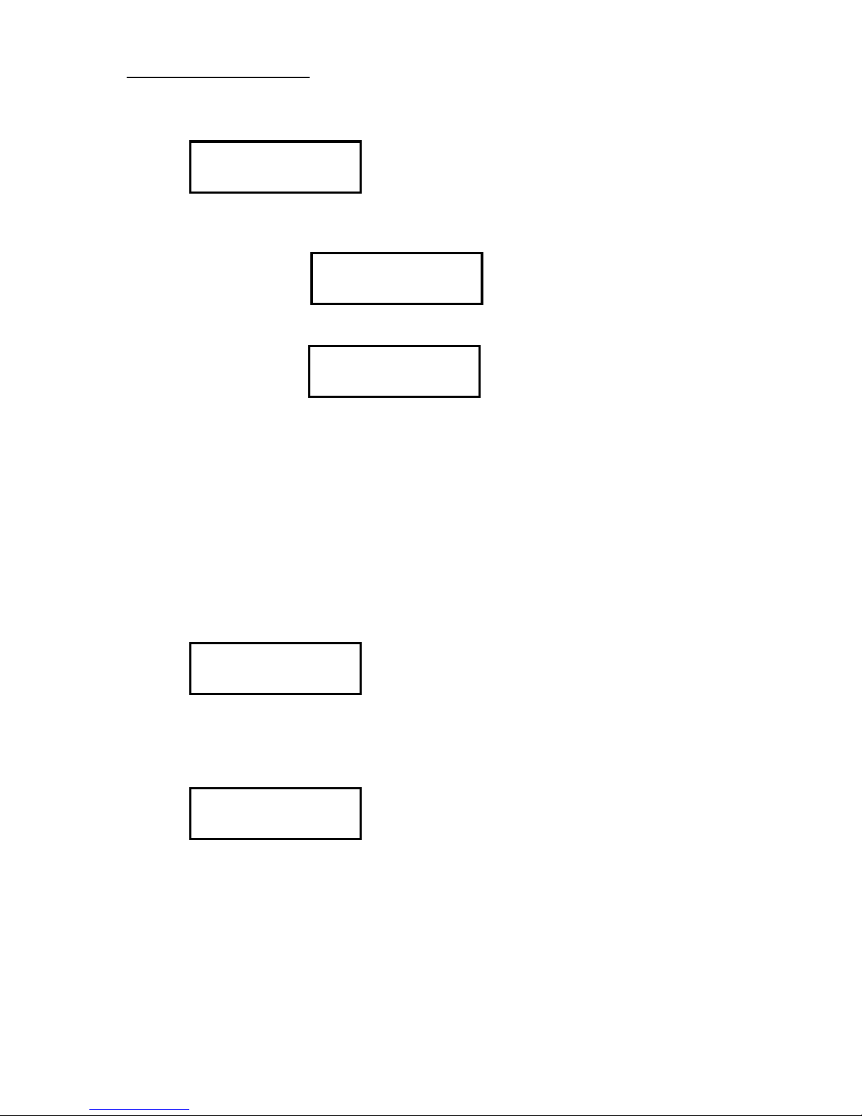
At start up the display appears as, (this will be referred in the manual as the Startup display):
From this display, the UP, DOWN, PROGRAM and MANUAL keys are active.
UP: This allows the desired rpm to be entered through the numerical keypad. The display will show
Actual RPM, Setpoint RPM and Elapsed Run Time. The unit will run until you press PAUSE or
STOP.
DOWN: This allows the desired rpm and run time to be entered using the numerical keypad. The
display will show Actual RPM, Setpoint RPM and RUN time left until the unit will shut down. The
unit can be stopped at any time by pressing PAUSE or STOP.
PROGRAM: This allows the programming of up to 23 cycles. Each cycle consists of a run time,
setpoint rpm and a pause time (except for the last cycle where there is no pause time). The
program can be stopped at any time while the motor is running by pressing PAUSE. This puts the
unit into a pause mode, from this point the program can then be canceled, continued, or restarted
from the beginning of the program.
NOTE: PRESSING "STOP" IN THE PROGRAM MODE STOPS THE CYCLE STEP THAT IS
CURRENTLY RUNNING AND PROCEEDS TO THE NEXT CYCLE STEP. "STOP" DOES NOT
STOP THE PROGRAM. See PROGRAM MODE for details on the use of STOP in the Program
Mode.
MANUAL: This allows you to manually control the rpms of the unit by pressing the UP and DOWN
ARROWS. The display will show Actual RPM, Setpoint RPM and Elapsed Run Time. The unit
can be stopped at anytime by pressing STOP.
Page 8
8
MANUAL MODE
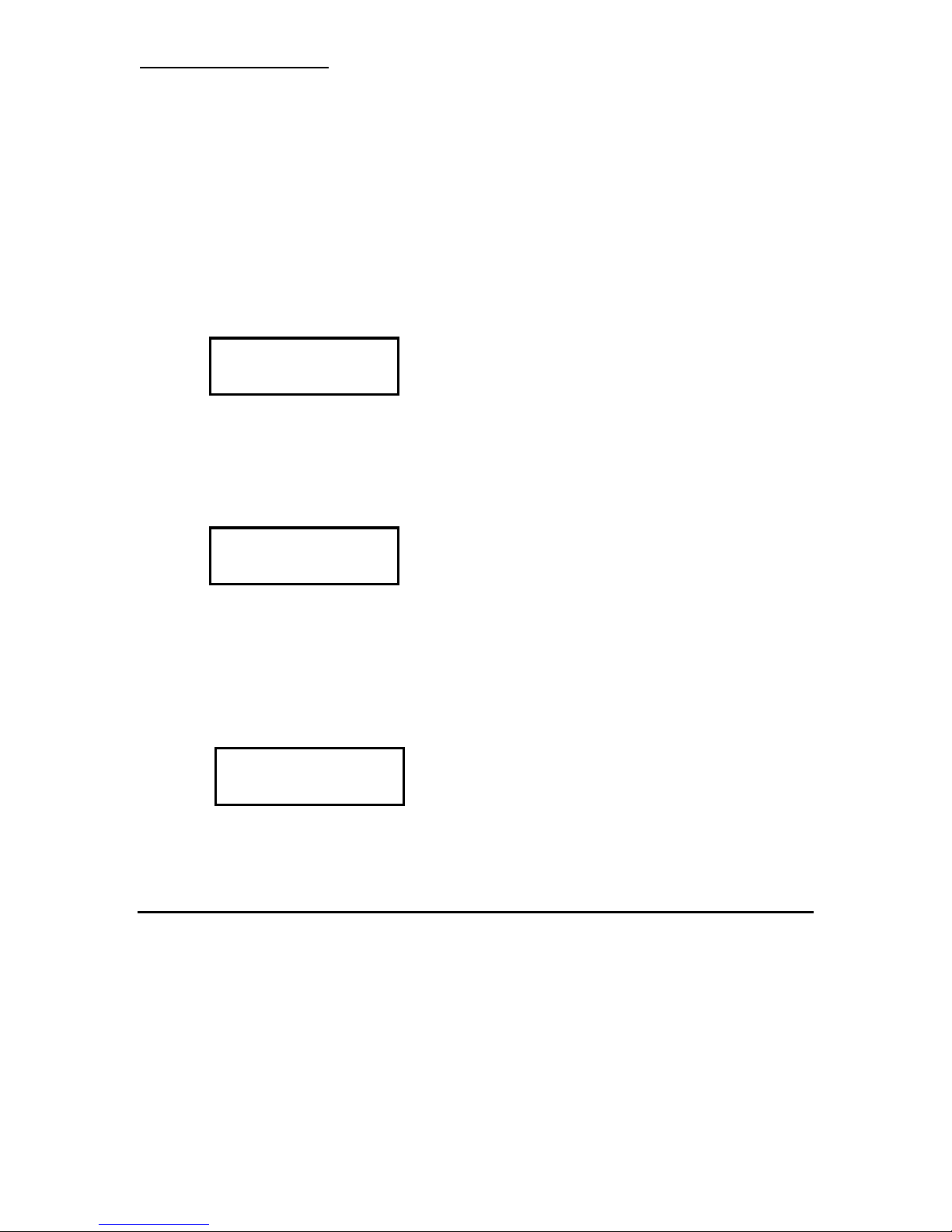
11200 11300
Timer: 00:00:32
11200 11300
Timer: 00:00:32
Press RUN to Restart
or CLEAR to Reset
1. Press MAN to activate the manual mode.
2. Press RUN to start the motor or CLEAR to abort.
3. Press the UP ARROW or the DOWN ARROW to increase/decrease the motor speed.
4. Pressing the UP ARROW for one beep will increase the speed by 100 RPM. Pressing the
DOWN ARROW for one beep will decrease the speed by 100 rpm. If you continue to hold down
the UP/DOWN ARROW the rate of speed change will increase.
Below is the display while running in MANUAL
Actual RPM Set point RPM
Time in HH: MM: SS Format
5. Pressing STOP will stop the motor. The last actual rpm, set point rpm and total running time will
stay displayed until CLEAR is pressed
Last Actual RPM Set point RPM
PRESS CLEAR blinks
Time in HH"MM"SS Format
Time shows last active timer display
6. Pressing CLEAR will activate the following display
7. Pressing RUN will restart the motor at the RPM it was running when it was stopped.
8. Pressing CLEAR will return you to the startup display.
Keys active in the MANUAL MODE
UP ARROW Used to increase motor speed
DOWN ARROW Used to decrease motor speed
RUN Used to start motor
STOP Used to stop motor
CLEAR Used to clear display after pressing the STOP key.
Page 9
9
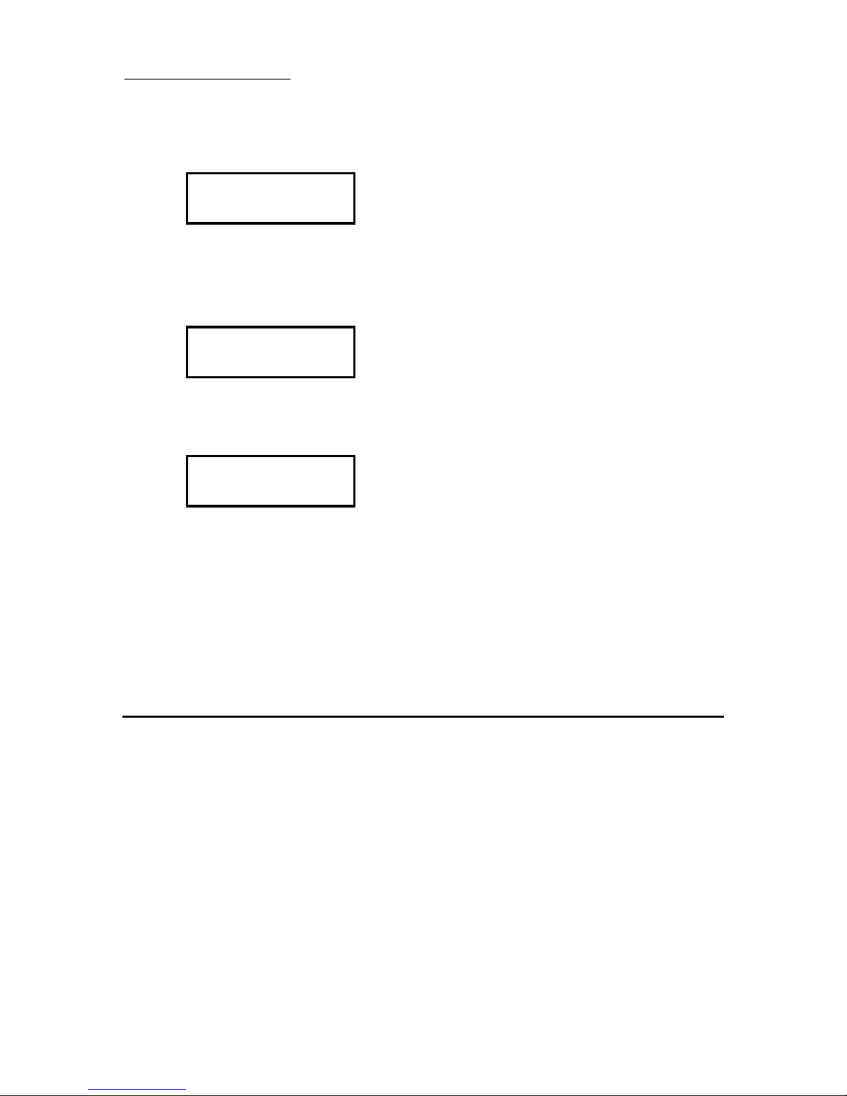
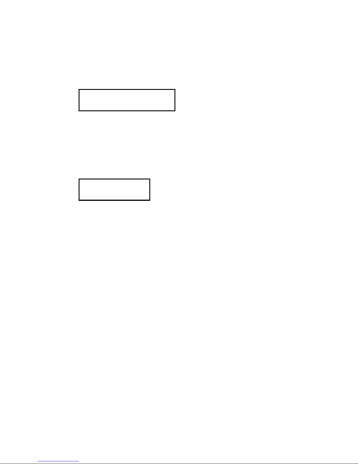
Enter rpm: 00000
11200 11300 PAUSE
Timer: 00:00:32
Press RUN to Restart
or CLEAR to Reset
AUTO UP MODE
1. Press UP to activate auto-up mode.
2. Enter the desired rpm using the numerical keys.
Press CLEAR to clear display Press ENTER to accept rpm setting
Press STOP to abort and return to start up display
3. The display will be as follows;
4. Press RUN to start the motor, or CLEAR to cancel and return to start up display
5. Press PAUSE to pause the motor and then RUN to restart.
Actual RPM Set point RPM
Time in HH:MM:SS Format
Time stops until motor is started again
6. Press STOP while the motor is running or in pause to cancel the run. The last actual rpm, set
point rpm and total running time will stay displayed until CLEAR is pressed.
7. Press CLEAR to activate the display.
8. Press RUN to restart the motor at the same rpm that was entered in step 2 and the time will
start again from 00:00:00.
9. Press CLEAR to activate the startup display.
Keys active in the Auto UP MODE
0-9 Used to enter rpm setpoint
ENTER Used to accept RPM setpoint
RUN Used to start the motor, or resume after pressing PAUSE.
PAUSE Used to pause the motor and timer. STOP Used to stop the motor.
CLEAR Used to clear the display after pressing the STOP key.
Page 10
10
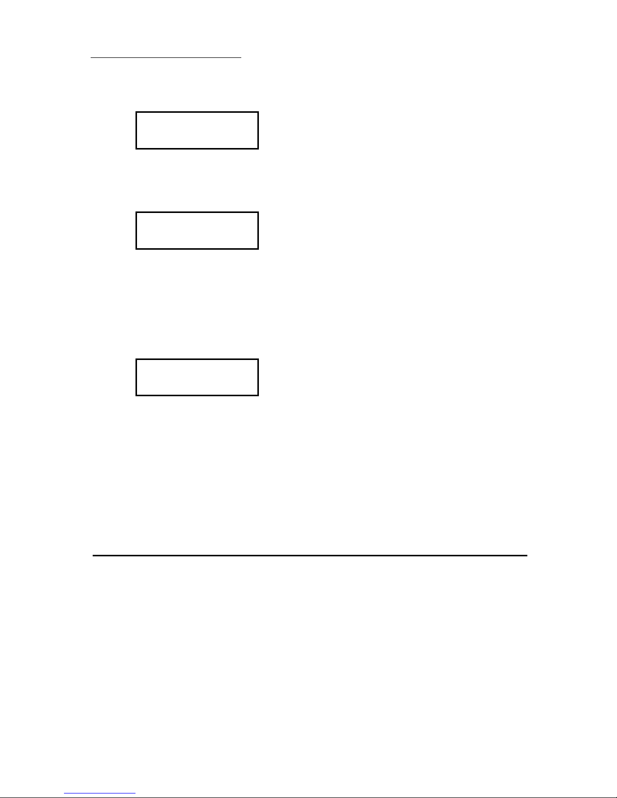
Timer: 00:00:00
Enter rpm: 00000
11200 11300 PAUSE
Timer: 00:00:32
AUTO DOWN MODE
1. Press DOWN to activate Auto DOWN mode.
2. Enter the desired run time using the numerical keys.
3. Press ENTER to accept the time entered.
4. Enter the desired rpm using the numerical keys
Press CLEAR to clear display.
Press ENTER to accept rpm setting
Press STOP to abort and return to start up display
5. Press RUN to start the motor, or CLEAR to cancel and return to the start up display
6. Press PAUSE to pause the motor and then RUN to restart
Actual RPM Setpoint RPM
The PAUSE blinks
Time in HH:MM:SS Format
Time stops until motor is started again
7. Press STOP while the motor is running or in pause to cancel the run. The display shown in
Figure 6 will be activated. The last actual rpm, setpoint rpm and time left on the timer will stay
displayed until CLEAR is pressed.
8. Pressing CLEAR will activate the RUN / CLEAR display.
9. Pressing RUN will restart the motor at the same rpm that was entered in step B and the time
will start again from 00:00:00. Pressing CLEAR will activate the startup display.
Keys active in the Auto DOWN MODE
0-9 Used to enter rpm setpoint.
ENTER Used to accept rpm setpoint.
RUN Used to start the motor, or resume after pressing PAUSE.
PAUSE Used to pause the motor and timer STOP Used to stop the motor.
CLEAR Used to clear the display after pressing the STOP key.
Page 11
11
No. of Cycles = 00
Enter = Accept
Timer: 00:00:00
Cycle 1 of 3
Load From Memory
1 = Yes 5 = No
Enter Program Numbers
1 2 3 4
2 = Review Program
3 = Continue
PROGRAM MODE
1. Press PROGRAM to activate the PROGRAM Mode.
2. The following will display:
3a. To load a saved program press 1. And follow the following saved program recall instructions.
1. Press appropriate number for saved program – up to 4 programs.
2. The following will display
3. Press 2 to review the cycle settings for the selected program.
a. All cycles settings can be edited at this time. Go to step 19 for
instructions.
4. Press 3 to activate the selected program without reviewing settings.
a. Press RUN to start program or clear to cancel.
3. Press 5 to create new program.
4. Enter the desired number of cycles to run. This can be any number from 1 to 23. The system
will not accept any number greater than 23. Each cycle consists of a:
Run Time (00:00:00)
RPM Setpoint (2,000 - 28,000) Pause Time (00:00:00)
5. Press ENTER to accept the number of cycles entered.
6. Enter the desired run time using the numerical keys for each cycle.
7. Press CLEAR to clear the display and re-enter the running time.
8. Press ENTER to accept the running time.
9. Press STOP to abort and return to the startup display.
Step 6 -9 will be repeated for each cycle.
Page 12

12
Enter rpm: 00,000
Cycle 1 of 3
PAUSE: 00:00:00
Timer CYC 1 of 3
2 = REVIEW PROGRAM
3 = CONTINUE
00:00:54 10000
P-00:00:09 CYCLE 1
10. Enter the desired rpm using the numerical keys for each cycle.
Current Cycle Total Number
being entered of cycles
11. Press CLEAR to clear the display and re-enter the rpms.
12. Press ENTER to accept the rpm settings.
13. Press STOP to abort and return to the startup display.
Step 10 - 13 will be repeated for each cycle
14. Enter the desired pause time using the numerical keys for each cycle.
Current Cycle being entered / Total number of cycles
15. Press CLEAR to clear the display and re-enter the pause time.
16. Press ENTER to accept the pause time.
17. Press STOP to abort and return to the startup display.
Step 14 - 17 will be repeated for each cycle
18. At the end of entering all of the pause times the following display will be activated.
19. Press 2 to review the cycle settings. The, following display will be activated.
RUN Time Set point RPM
RUN Setpoint Time RPM
___________
PAUSE Time CYCLE being looked at
The above display shows
RUN Time
Set point rpms
PAUSE Time
The cycle that is being reviewed
The above display is reviewing
I
Page 13
13
Cycle 1
CHANGE: 2 = RUN Time,
3 = RPM, 4 = PAUSE CYC2
Press RUN to Restart
or CLEAR to Reset
The RUN time is set for 54 seconds. The speed is set for 10,000 rpm
The PAUSE time is set for 9 seconds
To accept the values as they are press ENTER and the display will show the settings for the next
cycle.
To make a change, press the PAUSE key.
The following will be displayed
Press 2 to send the program to step 6-9 above.
Press 3 to send the program to step 10-13 above.
Press 4 to send the program to steps 14-17 above
The program will then go to step 19 above.
After reviewing all cycles or if key 3 was pressed in step 18, the following RUN / RESTART Screen
will display:
20. Press RUN to start the motor or CLEAR to cancel and return to the start up display.
21. While running: Pressing STOP will cancel the current step running and start the next
step.
CYC STEP OPERATION
Run 10 seconds at 10,000 rpm Pause for 12 seconds
Run 30 seconds at 20,000 rpm Pause for 8 seconds
Run 54 seconds at 27,500 rpm Pause for 34 seconds
Run 30 seconds at 9,000 rpm END
Cycle 2 Step 3 is active:
The motor is running at 20,000 rpm for 30 seconds STOP is pressed
Cycle 2 Step 3 is aborted
Cycle 2 Step 4 becomes active The motor stops
The timer begins to time down from 8 seconds STOP is pressed
Cycle 2 Step 4 is aborted
Cycle 3 Step 5 becomes active
The motor begins to run at 27,500 rpm
The timer begins to time down from 54 seconds
Pressing PAUSE while in a pause program step does nothing.
The PAUSE key only has an effect when the motor is running.
Pressing PAUSE while the motor is running stops the motor and suspends the timer. The display will
show a flashing PAUSE. The unit then waits for RUN or STOP to be pressed. If RUN is pressed
the motor restarts and the timer begins to resume timing. If STOP is pressed the program is aborted
and the REVIEW PROGRAM / CONTINUE screen is displayed.
Page 14

14
22. At the end of the program run the REVIEW PROGRAM / CONTINUE screen is displayed.
Press CLEAR to activate the start up display). Press RUN, the program will go to step 16 above.
Keys active in the PROGRAM MODE
0-9 Used to enter rpm setpoint
ENTER Used to accept rpm setpoint
RUN Used to start the motor, or resume after pressing PAUSE
PAUSE Used to pause the motor and timer STOP Used to stop the motor
CLEAR Used to clear the display after pressing the STOP key.
Page 15

15
02-05075
5 mm Diameter x 75 mm Long Flat Bottom Generator
02-07075
7 mm Diameter x 75 mm Long Saw Tooth Bottom Generator
02-07095
7 mm Diameter x 95 mm Long Saw Tooth Bottom Generator
02-07120**
7 mm Diameter x 120 mm Long Saw Tooth Bottom Generator
02-07150**
7 mm Diameter x 150 mm Long Saw Tooth Bottom Generator
02-10105
10 mm Diameter x 105 mm Long Saw Tooth Bottom Generator
02-10115
10 mm Diameter x 115 mm Long Saw Tooth Bottom Generator
02-10150**
10 mm Diameter x 150 mm Long Saw Tooth Bottom Generator
02-20105
20mm Diameter x 105 mm Long Saw Tooth Generator
02-20115
20 mm Diameter x 115 mm Long Saw Tooth Bottom Generator
02-20150**
20 mm Diameter x 150 mm Long Saw Tooth Bottom Generator
02-20200**
20 mm Diameter x 200 mm Long Saw Tooth Bottom Generator
02-20340**
20 mm Diameter x 340 mm Long Saw Tooth Bottom Generator
02-30115
30 mm Diameter x 115 mm Open Slotted Generator
02-30150**
30 mm Diameter x 150 mm Open Slotted Generator
02-30200**
30 mm Diameter x 200 mm Open Slotted Generator
02-30340**
30 mm Diameter x 340 mm Open Slotted Generator
02-37115
37 mm Diameter x 115 mm Open Slotted Generator
02-37150**
37 mm Diameter x 150 mm Open Slotted Generator
02-37200**
37 mm Diameter x 200 mm Open Slotted Generator
02-37340**
37 mm Diameter x 340 mm Open Slotted Generator
02-43115
43 mm Diameter x 115 mm Open Slotted Generator
02-43150**
43 mm Diameter x 150 mm Open Slotted Generator
02-43200**
43 mm Diameter x 200 mm Open Slotted Generator
02-43340**
43 mm Diameter x 340 mm Open Slotted Generator
02-50150
50 mm Diameter x 150 mm Long Cryogenic Generator
02-59115
59 mm Diameter x 115 mm Open Slotted Generator
02-59150
59 m Diameter x 150 mm Open Slotted Generator
02-59200**
59 mm Diameter x 200 mm Open Slotted Generator
02-59340**
59 mm Diameter x 340 mm Open Slotted Generator
02-70150
70 mm Diameter x 150 mm Long Cryogenic Generator
02-30200HD
30 mm Diameter x 200 mm Open Slotted "HD" Series Generator
02-37200HD
37 mm Diameter x 200 mm Open Slotted "HD" Series Generator
02-43200HD
43 mm Diameter x 200 mm Open Slotted "HD" Series Generator
02-59200HD
59 mm Diameter x 200 mm Open Slotted "HD" Series Generator
Generators/Sealed Chambers Recommended:
**Important information for generators with a length greater than 115mm
To ensure proper homogenization and to protect both the generator and sample,
generators with a length greater than 115mm should only be used when the sample height
in your tube/container comes at least half way up the generator shaft. Check the generator
sizes located above for the length you are interested in and compare it to your total
Page 16

16
sample height to be homogenized to ensure that your sample height is equal to or greater
02-070MG-12
Multi-Gen 7mm 316 stainless steel generators (12/pk)
02-070MG-24
Multi-Gen 7mm 316 stainless steel generators (24/pk)
02-070MG7XL-12
12-pack of MULTI-GEN 7XL generators
15-32002
ST-2 Sealed Tube Assembly W/5 mm Generator For 1.5/2.0 ml
Tubes
15-32005
ST-5 Sealed Tube Assembly W/ 5 mm Generator For 5 ml
Tubes
15-32010
ST-10 Sealed Tube Assembly W/ 7 mm Generator For 18 ml
Tubes
15-32015
ST-15 Sealed Tube Assembly W/ 7 mm Generator For 19 ml
Tubes
15-32050
ST-50 Sealed Tube Assembly W/ 10 mm Generator For 50 ml
Tubes
15-32050-20
ST-50 Sealed Tube Assembly W/ 20 mm Generator For 50 ml
Tubes
15-09070
70 ml Stainless Steel Chamber Assembly W/ 1" Diameter Blade
15-09600
600 ml Stainless Steel Chamber Assembly W/ 2" Diameter
Blade
15-19473
473 ml Glass Chamber Assembly W/ 2" Diameter Blade
15-19946
946 ml Glass Chamber Assembly W/ 2" Diameter Blade
15-02070-10
70 ml Chamber Assembly W/ 10 mm Diameter Generator
15-02070-20
70 ml Chamber Assembly W/ 20 mm Diameter Generator
15-02600-20
600 ml Chamber Assembly W/ 20 mm Diameter Generator
15-02600-30
600 ml Chamber Assembly W/ 30 mm Diameter Generator
15-081200
1200 ml Chamber Assembly W/ 70 mm Diameter Cryogenic
Generator
15-12473-20
473 ml Chamber Assembly W/ 20 mm Diameter Generator
15-12473-30
473 ml Chamber Assembly W/ 30 mm Diameter Generator
15-12946-20
946 ml Chamber Assembly W/ 20 mm Diameter Generator
15-12946-30
946 ml Chamber Assembly W/ 30 mm Diameter Generator
than half of the generator length.
(See Generators section for installation and usage instructions)
Page 17

17
PRO Generators Introduction
Description:
PRO Scientific believes that as homogenizing requirements increase from hand
held units to bench top laboratory units, interchangeability of generators is a
necessity. All of the PRO generators will fit any of the PRO homogenizers.
The ability to scale-up in size is important, therefore, all of the generators are
designed with this in mind. The choice of a generator depends on the end result
desired and the material being treated. One of the most important items to
consider in choosing a generator is the peripheral speed, which is critical for
particle size reduction. The following shows the peripheral speeds that the
individual units can reach in the medium:
5mm diameter generators = 6 meters per second
7mm diameter generators = 9 meters per second
10mm diameter generators = 13 meters per second
20mm diameter generators = 26 meters per second
30mm diameter generators = 39 meters per second
37mm diameter generators = 49 meters per second
43mm diameter generators = 57 meters per second
59mm diameter generators = 78 meters per second
70mm diameter generators = 92 meters per second
The generators all work on the same principal. The medium to be processed is
pulled into the bottom of the tube by the rotor and forced out the sides through
the stator slots. The stator acts as an ideal flow breaker and prevents, to a large
extent, the rotation of the medium and allows the introduction of large
mechanical energies in a very small space. The vortex formation known in
stirring is greatly reduced but cannot be avoided altogether. In the shearing gap
between the rotor stator, about 1,000 times more energy is introduced into the
medium than in stirring. The particles are pulled into the center of the rotor and
then forced radially outward. In this process the particles, by hitting sharp
edges and along with cavitation, are reduced in size. It usually takes only a few
minutes to obtain a fine particle size reduction. Longer processing times
achieve only a minor improvement in particle size and reduction while
increasing the temperature of the medium through the energy input.
Attaching the Generator to the Motor Unit:
1) All generators are fitted to the motor unit by inserting the upper end of
the generator into the collar end of the motor.
2) Align the vertical slots in the generator with the locating pins in the
motor collar by rotating the generator.
3) Once aligned, push the generator inward as far as possible and turn the
generator counter-clockwise. The collar is spring loaded so you will
feel some resistance as you push the generator inward and turn it.
4) Once you have turned the generator as far as it will go, release the
generator and you will hear a distinct click which is the generator
dropping into its locked position.
5) To prevent the generator from disengaging while being used, insert the
safety clip between the upper collar of the generator and the bottom of
the motor collar.
Page 18

18
6) To disconnect the generator from the motor unit, remove the safety
clip, push the generator up into the motor collar as far as possible and
turn the generator clockwise ½ turn. The generator will be pushed out
of the motor collar by the force of the internal spring.
Operating Procedures:
1) The generator may be used with either an open chamber or within a sealed
chamber assembly.
2) The ideal situation is when the diameter of the generator is as large as the
container will allow.
3) Insert the generator into the medium that is to be homogenized. The depth to
which the generator is inserted should normally be between ½ to 1/3 of the
liquid’s height measured from the bottom of the container. According to the
properties of the material, it may not be necessary to insert the generator to this
depth. In case of heavy sediments, the generator may have to be positioned lower,
but the generator must never come in contact with the bottom of the vessel.
4) MID-BEARING NOTE: All generators that are 120mm in length and longer
contain a mid-bearing, which is located inside the generator approximately half
way up the shaft. The mid-bearing must be lubricated by the sample/liquid during
processing, therefore the sample volume should cover about half the length of the
generator.
5) Start the drive unit at the lowest possible speed and then slowly increase the speed
to the desired level.
6) It is advisable that the generator be immersed within the container off-center. This
off-center location will help minimize vortexing as well as the undesirable
introduction of air into the sample.
7) The generators have two (2) sets of venting holes. One set is located
approximately 1" from the bottom of the generator and the second set is
approximately 1" below the bottom of the generator collar. The lower hole aids in
keeping the lower bearing lubricated, while the top hole allows venting of any
liquid that might be forced up into the tube. There is no need to avoid liquid from
entering the lower set of holes.
8) Once you have reached the level of processing that is required, reduce the motor
speed and start to slowly remove the generator from the container while the motor
is still running. It is important that this be done slowly as you want to spin all
medium from the generator back into the container and not outside of the
container.
9) After spinning the medium off the generator, the motor can be turned off and the
generator totally removed from the container.
Page 19

19
Cleaning and Lubrication:
1) Cleaning - Immediately after you have finished working with the generator, the
generator must be cleaned so that the substance residues do not stick to the rotor
and stator and allow small bacterial cultures to form in undesirable places. For
this purpose, the generator should be run in a solvent, which dissolves the
substance residue and does not harm the components. The rotor and stator are
cleaned as the solvent is pumped through the generator.
2) Sterilization
a. Chemical process - Germicidal solutions (formalin, phenol, alcohol etc.)
can disinfect in most cases. However, residues of the germicide must
subsequently be removed with sterilized water.
b. Sterilizing by humid heat - This means sterilizing with steam at a pressure
of 2 bar above atmosphere and a temperature of 120oC.
c. Sterilizing by hot air - Hot air sterilization is normally carried out at 160 to
190oC.
d. Flaming - This method can be used, however, it is only effective on
external surfaces.
Dismantling the Generator for Cleaning.
The following instructions are for the dismantling of only 5mm generators.
a. Unscrew the rotor knife from the bottom of the rotor shaft. Insert the 1/4"
hex key (supplied in the tool kit) into the end of the rotor shaft collar and
insert the screwdriver (supplied in the tool kit) into the rotor knife and turn
the hex wrench counter clockwise.
b. Remove the rotor knife from the bottom of the generator tube and collar
assembly.
c. Draw the rotor shaft and rotor shaft collar assembly upwards out of the
tube and collar assembly. The PTFE (polytetrafluoroethlyene) washer can
be removed from the rotor shaft.
d. Draw the upper bearing out of the top of the tube and collar assembly. The
upper bearing should be replaced when it shows signs of wear and before
the rotor shaft collar starts to come in contact with the inside wall of the
motor collar or starts to rub on the top of the tube and collar assembly.
e. Remove the lower bearing from the bottom of the tube and collar
assembly. The lower bearing should be replaced when worn before the
rotor knife starts to rub against the side of the stator.
f. The rotor shaft collar assembly can be removed from the rotor shaft by
loosening the set screw located at the side of the rotor shaft collar using
the hex wrench end of the screw driver (supplied in the tool kit).
The following instructions are for the dismantling of all other generators.
a. Unscrew the rotor knife from the bottom of the rotor shaft. Insert the ¼”
hex key (supplied in the tool kit) into the end of the rotor shaft collar and
insert the screwdriver end, which is a hex key tool, (supplied in the tool
kit) into the rotor knife and turn the hex wrench counter clockwise.
b. Remove the rotor knife from the bottom of the generator tube and collar
assembly
Page 20

20
c. Remove the rotor shaft collar assembly by loosening the setscrew located
in the side of the rotor shaft collar from the rotor shaft using the hex
wrench end of the screwdriver tool (Do not unscrew the setscrew from
within the rotor shaft collar assembly).
d. Remove the PTFE washer from the rotor shaft. Draw the rotor shaft
downwards out of the tube and collar assembly. (If rotor shaft does not
slide out, press down on the rotor shaft from the top of the generator tube
and collar assembly using the hex wrench end of the screwdriver tool).
e. Remove the lower bearing from the end of the tube and collar assembly
using the screwdriver. The screwdriver should be inserted high enough to
reach the inner side of the lower bearing. Put the flat side of the
screwdriver against the lower bearing, and then pull the handle of the
screwdriver against the saw-teeth or open-slotted end of the generator
probe. The lower bearing should come out. The lower bearing should be
replaced when it shows signs of wear and before the rotor shaft collar
starts to come in contact with the inside wall of the motor collar or starts
to rub on the top of the tube and collar assembly.
f. Cleaning – The generator is rinsed in a cleaning material or solvent. The
solvent must not attack stainless steel or PTFE. For a thorough cleaning
the generator must be dismantled, as the medium also wets the inner wall
of the tube.
g. Sterilization – After cleaning, the sterilization methods previously
mentioned are suitable for sterilizing these generators.
Assembly of the Generator:
The following instructions are for the assembly of only 5mm generators.
1) Insert the lower bearing into the bottom of the tube and collar assembly. Take the
rotor knife and place it into the bottom of the tube and collar assembly and push the
lower bearing into its proper location. The proper location is when the end of the rotor
knife is flush with the bottom of the tube and collar assembly.
2) Insert the upper bearing into the top of the tube and collar assembly. Proper
positioning of the upper bearing is when the flange of the bearing is firmly seated
against the top of the tube and collar assembly.
3) Attach the rotor shaft collar to the end of the rotor shaft. Make sure that the setscrew
in the rotor shaft collar lines up with the flat on the end of the rotor shaft. The rotor
shaft collar should be located as close to the end of the rotor shaft as possible. Slide
the PTFE washer up the rotor shaft until it contacts the rotor shaft collar.
4) Insert the rotor shaft with the rotor shaft collar and PTFE washer attached into the
upper end of the tube and collar assembly.
5) The rotor shaft should rotate freely within the tube and collar assembly. If the rotor
shaft does not rotate freely, remove the rotor shaft from the tube and collar assembly
and inspect both the upper and lower bearings for any possible damage. Replace any
damaged bearings.
6) Insert the rotor knife into the end of the tube and collar assembly and rotate the knife
clockwise while holding the rotor shaft collar.
7) Once the rotor knife is threaded onto the end of the rotor shaft, insert the ¼” hex
wrench into the end of the rotor shaft collar and the screwdriver into the end of the
rotor knife and lightly tighten.
Page 21

21
8) With the rotor knife attached, place the generator with the blade end downward onto a
flat surface. Loosen the setscrew located on the side of the rotor shaft collar. Push the
rotor shaft collar downward until the PTFE washer is in contact with both the bottom
of the rotor shaft collar and the top of the upper bearing. Tighten the set screw and
check that the generator rotates freely.
The following instructions are for the assembly of all other generators.
1) Attach the rotor knife to the rotor shaft by screwing it together until tight (hand
tighten). Slide the lower bearing onto the rotor shaft until it reaches the rotor knife.
2) Insert the Rotor Shaft into the end of the tube and collar assembly. Then push the
rotor knife up into the end of the tube and collar assembly until it cannot go any
further. This will put lower bearing into place. The rotor shaft should be seen at the
top of the tube and collar assembly.
3) While pushing against the rotor knife, put the rotor collar assembly onto the rotor
shaft.
4) While holding the rotor knife, locate the setscrew on the side of the rotor shaft collar
and locate the flat end of the rotor shaft to be facing each other. Once locations are
lined up with one another, tighten the setscrew against the flat end of the rotor shaft
using the hex wrench end of the screwdriver tool (supplied in the tool kit).
Page 22

22
PRO Multi-Gen Introduction
PRO Multi-Gen Adapters And Generators:
The Multi-Gen generators and adapters have been
designed to allow continuous processing without
having to clean or decontaminate the generator between samples. Constructed with 316
stainless steel and PTFE, the Multi-Gen generator can be autoclaved assembled or in
parts. The Multi-Gen adapter allows the Multi-Gen generators to be attached to and used
with any PRO homogenizer motor unit.
Attachment of the Adapter to the Drive Motor:
1) Remove the adapter from the shipping package.
2) Align the grooves in the side of the adapter’s upper collar with the two (2) pins in
the bottom of the motor collar.
3) Push the adapter into the motor collar.
4) Once inserted as far as it will go, turn the adapter counter-clockwise until you feel
the adapter lock into place. This should be approximately a 1/2 turn.
5) Once the adapter is attached to the motor collar, it is important that the safety clip
supplied with the adapter be inserted between the bottom of the motor collar and
the shoulder of the adapter. Proper insertion of the safety clip will prevent the
adapter from disengaging from the motor collar when ejecting the used generator.
Attachment of the Multi-Gen Generator to the Adapter
1) Remove one generator from the box.
2) Push the bottom sleeve on the adapter upward.
3) With the sleeve pulled back, insert the grooved end of the generator into the
bottom of the adapter.
4) Once the generator has been inserted as far as possible into the bottom of the
adapter, the bottom sleeve of the adapter can be released. Releasing the bottom
sleeve will lock the generator in place. Pulling gently on the generator will ensure
that the generator is securely in place.
Removal of the Multi-Gen Generator from the Adapter
1) With the motor in an upward position, (generator pointing downward), slide the
bottom of the adapter upward. Sliding the bottom sleeve of the adapter upward
will allow the generator to drop out of the adapter.
Please refer to the Multi-Gen generators instructions that were included with your MultiGen Generator Pack for further instructions on disassembly, assembly and cleaning.
Page 23

23
PRO Sealed Chamber Assembly Introduction
Sealed Chamber Assembly with a Blade:
The sealed chambers are by far the industry’s safest method of homogenizing with
either a blade or a rotor stator generator. The unique design of the sealed chamber
assembly does not allow the user to operate the system with the blade exposed. The
blade assembly can not be engaged to the drive motor unless the chamber is attached. In
addition to preventing the operator from being exposed to a rotating blade, the sealed
chamber assembly protects the operator from hazardous aerosols generated during
homogenizing.
Completing the Chamber Assembly With a Blade
All chamber assemblies using a blade are completed as follows:
1) Screw the rotor shaft assembly into the cover plug. Tighten snugly using the
multi-wrench (supplied in the tool kit).
2) With the sharpened side of the blade up, mount the blade on the rotor shaft
engaging the tabs in the knife collar with the cutout in the center of the blade
and secure with the acorn nut.
WARNING: The knife blades are surgically sharpened and should be handled
carefully to avoid injury.
3) Tighten snugly with the multi wrench, while holding the rotor shaft steady with
the 1/4"hex wrench.
4) Insert the rotor shaft assembly and cover plug with the blade attached into the
chamber.
5) Screw the chamber cover onto the chamber. Note that the threads on the
chamber and cover are left hand threads and are screwed together by turning the
cover counter clockwise. These two parts should be tightened securely. There is
no way in which the blade can be attached to the motor unit without the chamber
being attached. This is to ensure that the operator is never exposed to a rotating
blade.
6) Attach the chamber assembly to the motor as follows:
a. Insert the upper end of the chamber assembly into the motor collar.
b. Align the slots in the top of the chamber assembly with the locating pins
in the motor collar by rotating the chamber assembly as you insert it into
the collar.
c. Once aligned, push the chamber assembly inward as far as possible and
turn the chamber assembly counter-clockwise 1/2 turn. The collar is
spring loaded so you will feel some resistance as you push the chamber
assembly inward and turn it.
d. Once you have turned the chamber assembly as far as it will go, release
the chamber assembly and you will hear a distinct click which is the
chamber assembly dropping into its locked position.
e. Insert the safety clip between the top of the chamber lid and the bottom
of the motor collar.
f. Lower the entire motor unit on the stand until the bottom of the chamber
assembly is resting on the tabletop, the bottom of the cooling/heating
vessel or the top of a height block.
Page 24

24
WARNING: Even when the homogenizer uses the sealed chamber assemblies, the
chamber assembly should still be operated only with the bottom of the chamber
assembly resting on the tabletop, the bottom of the cooling/heating vessel or the top
of a height block.
g. To disconnect the chamber assembly from the motor unit, remove the
safety clip, push the chamber assembly upward into the motor collar as
far as necessary to allow you to turn the chamber assembly clockwise 1/2
turn. The internal spring will push the assembly downward and out of the
motor collar.
Using the Chamber Assembly with a Blade:
The various chamber assemblies (stainless steel, glass and plastic) can be used for
homogenization of materials in the liquid/liquid, liquid/solid, and solid/solid states.
Homogenization and mixing will normally be completed within 30 seconds to one
minute. At revolutions higher than 8,000 rpm the time of mixing should be limited to
three minutes with dry mixtures and ten minutes for liquids. To homogenize solid
materials it is advisable to chop up pieces larger than 1.0 cm in diameter before putting
them into the chamber.
Operation Procedures:
Assemble the cover/cover plug and rotor shaft assembly. Load the material to be
processed into the chamber. It is recommended that the chamber be filled only to
approximately 75% of its total volume. Attach the filled chamber to the cover and cover
plug/rotor shaft assembly and attach it to the motor.
WARNING: The homogenizer should only be operated with the bottom of the
chamber assembly resting on the tabletop, the bottom of the cooling or heating
vessel or the top of a height block.
Rotate the speed control dial until the desired speed is reached. When the desired time
period has elapsed, turn the “ON/OFF” switch position. Remove the chamber assembly
from the motor unit before opening the chamber assembly.
Operation Techniques:
To use the homogenizer effectively, the following techniques are recommended:
WARNING: When it is necessary to use volatile, flammable, toxic, pathogenic,
radioactive or other hazardous materials, standard laboratory precautions should
be followed, such as venting, operating in a fume hood, etc. The homogenizer is not
made of an explosion-proof construction.
1) Cooling - At revolutions above 5,000 rpm, relatively high temperatures are
generated. Therefore, the chamber should be cooled whenever operating at speeds
Page 25

25
above 5,000 rpm by immersing the chamber in an ice bath or similar cooling
vessel.
2) Ball Milling - At revolutions below 5,000 rpm, particles may be broken down by
using hard materials, such as glass beads. The homogenizer will act as a “ball
mill” agitating the chamber while the hard materials do the work. Since sharpness
is not essential, a dull knife blade should be used.
3) Homogenizing - For more complete homogenization of some materials, it is
helpful to rock the motor unit slightly to churn up the specimen within the
chamber.
4) Adding a grinding medium - To attain the desired effect (cell breakdown), a
combination of procedures may be necessary. First, homogenize the specimen in
solution using speed and a sharp knife blade. Then change the knife blade, add a
grinding medium and run the homogenizer at maximum speed of 5,000 rpm for
ten to fifteen minutes.
Cleaning and Lubrication:
To prevent contamination of specimens, always clean the chamber assembly as soon as
possible after use. Some acceptable methods of cleaning are as follows:
1) Cleaning - Run the chamber assembly with a solvent added which will dissolve
the substance residue and not harm components. The rotor shaft and blade as well
as the chamber are cleaned as the solvent is mixed within the chamber assembly.
2) Sterilization - It is recommended that the chamber assembly be disassembled
prior to sterilization. Disassemble the chamber assembly by reversing the
assembly procedure. All parts of the chamber assembly are autoclavable.
a. Chemical processes - Germicidal solutions (formalin, phenol, alcohol,
etc.) can disinfect in most cases. However, residues of the germicide must
subsequently be removed with sterilized water.
b. Sterilizing by humid heat - This means sterilizing with steam at a pressure
of 2 bar above atmosphere and at a temperature of 120oC.
c. Sterilizing by hot air - Hot air sterilization is normally carried out at 160 to
190o C.
d. Flaming - This method can be used, however, it is only effective on
external surfaces.
Page 26
26
Part
Number
Size
mmXmm
Rotor
Collar
Rotor
Shaft
PTFE
Washer
Upper
Bearing
Middle
Bearing
Tube
and
Collar
Lower
Bearing
Rotor
Knife
(1)
(2)
(3)
(4)
(5)
(6)
(7)
(8)
02-05075
5 X 75
07-00150
05-05075
99-03302
03-10001
N/A
08-05075
03-21002
04-05150
02-05150
5 X 150
07-00150
05-05150
99-03302
03-10001
03-21102
08-05150
03-21002
04-05150
02-07075
7 X 75
07-00150
05-07075
99-03302
03-10001
N/A
08-07075
03-21003
04-07150
02-07095
7 X 95
07-00150
05-07095
99-03302
03-10001
N/A
08-07095
03-21003
04-07150
02-07120
7 X 120
07-00150
05-07120
99-03302
03-10001
03-21103
08-07120
03-21003
04-07150
02-07150
7 X 150
07-00150
05-07150
99-03302
03-10001
03-21103
08-07150
03-21003
04-07150
02-10105
10 X 105
07-00150
05-10105
99-03302
03-10001
N/A
08-10105
03-21004
04-10150
02-10115
10 X 115
07-00150
05-10115
99-03302
03-10001
N/A
08-10115
03-21004
04-10150
02-10150
10 X 150
07-00150
05-10150
99-03302
03-10001
03-21104
08-10150
03-21004
04-10150
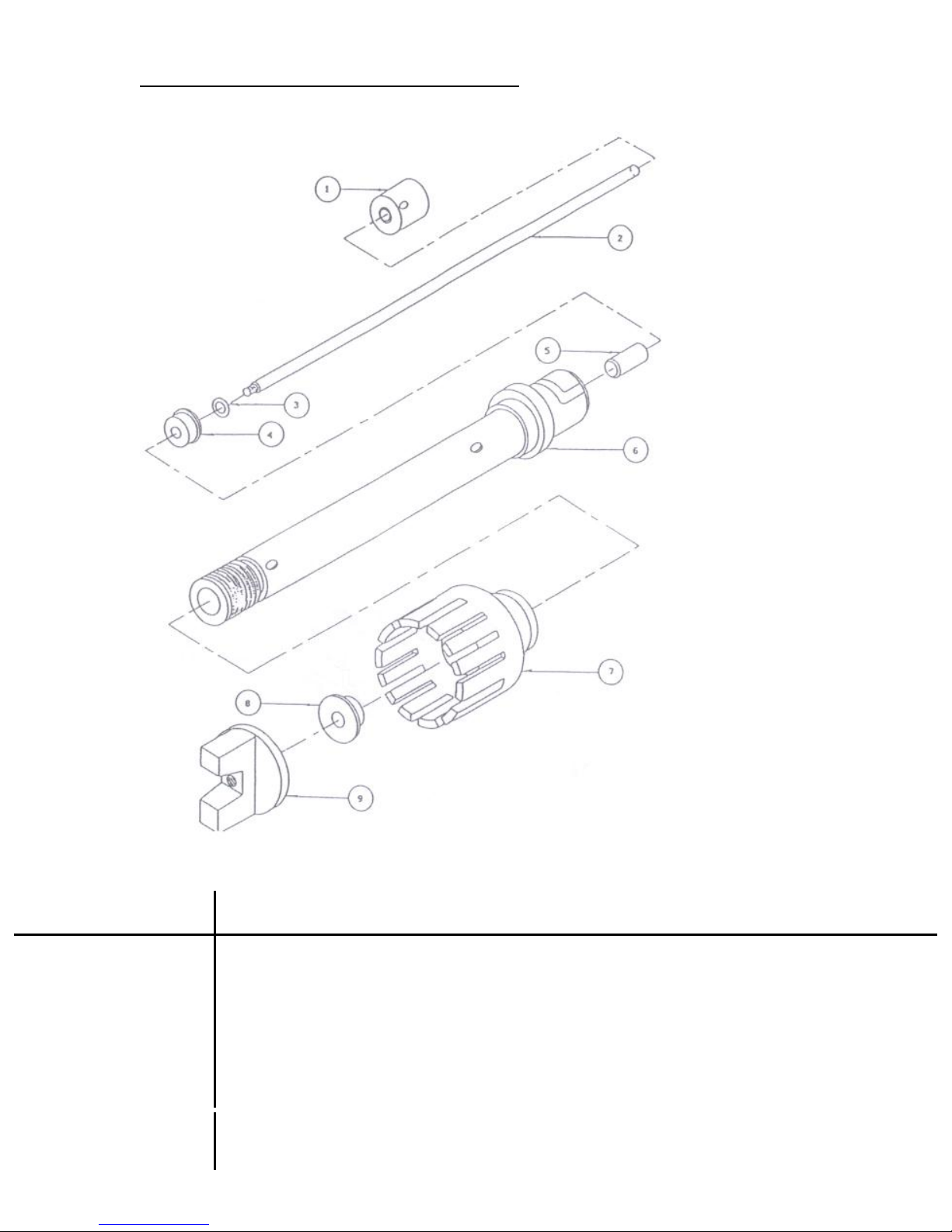
PRO Generator Index: Drawings And Part List
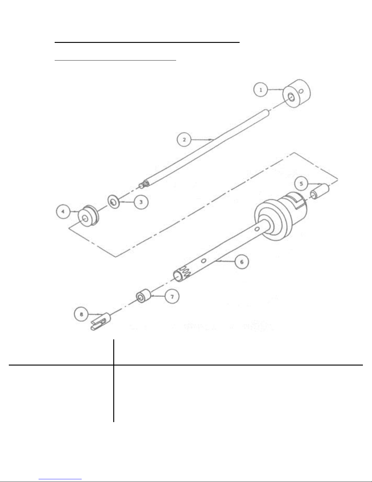
5mm, 7mm, and 10mm Generators:
Use the drawing below to assist with the generators listed.
(10mm X 150mm)
Page 27
27
Part
Number
Size
mmXmm
Rotor
Collar
Rotor
Shaft
PTFE
Washer
Upper
Bearing
Middle
Bearing
Tube
and
Collar
Lower
Bearing
Rotor
Knife
(1)
(2)
(3)
(4)
(5)
(6)
(7)
(8)
02-20105
20 X 105
07-00150
05-20105
99-03302
03-10001
N/A
08-20105
03-11005
04-20150
02-20115
20 X 115
07-00150
05-20115
99-03302
03-10001
N/A
08-20115
03-11005
04-20150
02-20150
20 X 150
07-00150
05-20150
99-03302
03-10001
03-21104
08-20150
03-11005
04-20150
02-20200
20 X 200
07-00150
05-20200
99-03302
03-10001
03-21104
08-20200
03-11005
04-20150
02-20340
20 X 340
07-00150
05-20340
99-03302
03-10001
03-21104
08-20340
03-11005
04-20150
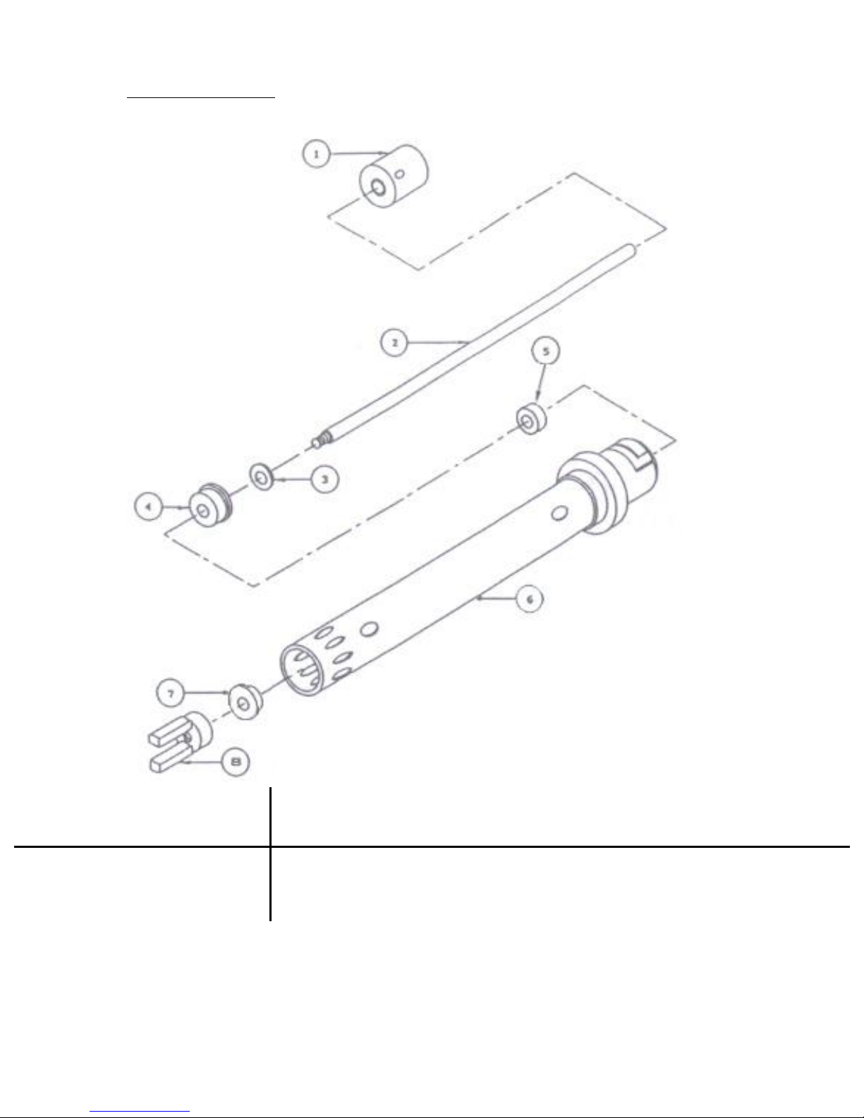
20mm Generators:
Use the drawing below to assist with the generators listed.
(20mm X 200mm)
Page 28
28
Part
Number
Size
mmXmm
Rotor
Collar
Rotor
Shaft
PTFE
Washer
Upper
Bearing
Middle
Bearing
Tube and
Collar
Rotor
Head
Lower
Bearing
Rotor
Knife (1)
(2)
(3)
(4)
(5)
(6)
(7)
(8)
(9)
02-30115
30 X 115
07-00150
05-20115
99-03302
03-10001
N/A
08-01115
16-30150
03-11037
04-30150
02-30150
30 X 150
07-00150
05-20150
99-03302
03-10001
03-21104
08-01150
16-30150
03-11037
04-30150
02-30200
30 X 200
07-00150
05-20200
99-03302
03-10001
03-21104
08-01200
16-30150
03-11037
04-30150
02-30340
30 X 340
07-00150
05-20340
99-03302
03-10001
03-21104
08-01340
16-30150
03-11037
04-30150
02-37115
37 X 115
07-00150
05-20115
99-03302
03-10001
N/A
08-01115
16-37150
03-11037
04-37150
02-37150
37 x 150
07-00150
05-20150
99-03302
03-10001
03-21104
08-01150
16-37150
03-11037
04-37150
02-37200
37 x 200
07-00150
05-20200
99-03302
03-10001
03-21104
08-01200
16-37150
03-11037
04-37150
02-37340
37 x 340
07-00150
05-20340
99-03302
03-10001
03-21104
08-01340
16-37150
03-11037
04-37150
02-43115
43 x 115
07-00150
05-20115
99-03302
03-10001
N/A
08-01115
16-43150
03-11037
04-43150
02-43150
43 x 150
07-00150
05-20150
99-03302
03-10001
03-21104
08-01150
16-43150
03-11037
04-43150
02-43200
43 x 200
07-00150
05-20200
99-03302
03-10001
03-21104
08-01200
16-43150
03-11037
04-43150
02-43340
43 x 340
07-00150
05-20340
99-03302
03-10001
03-21104
08-01340
16-43150
03-11037
04-43150
02-59115
59 x 115
07-00150
05-20115
99-03302
03-10001
N/A
08-01115
16-59150
03-11037
04-59150
02-59150
59 x 150
07-00150
05-20150
99-03302
03-10001
03-21104
08-01150
16-59150
03-11037
04-59150
02-59200
59 x 200
07-00150
05-20200
99-03302
03-10001
03-21104
08-01200
16-59150
03-11037
04-59150
02-59340
59 x 340
07-00150
05-20340
99-03302
03-10001
03-21104
08-01340
16-59150
03-11037
04-59150
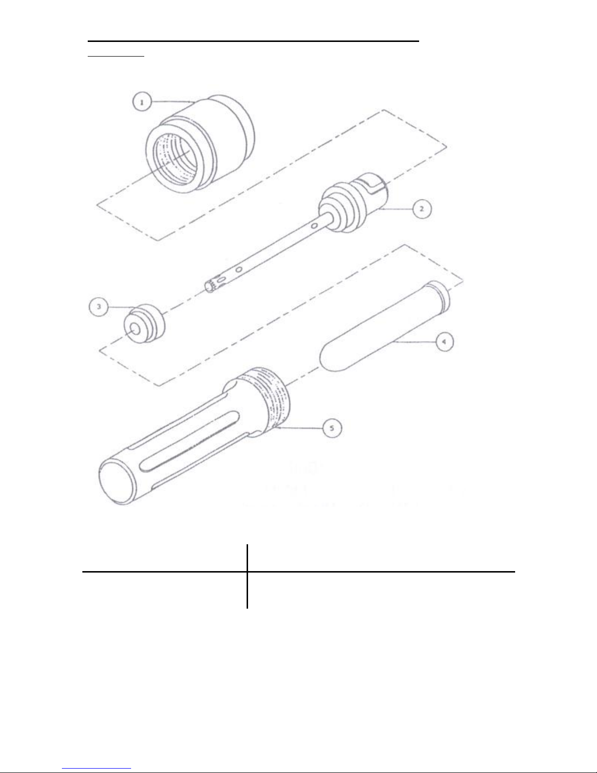
30mm, 37mm, 43mm & 59mm Generators:
Use the drawing below to assist with the generators listed.
(30mm X 200mm)
Page 29
29
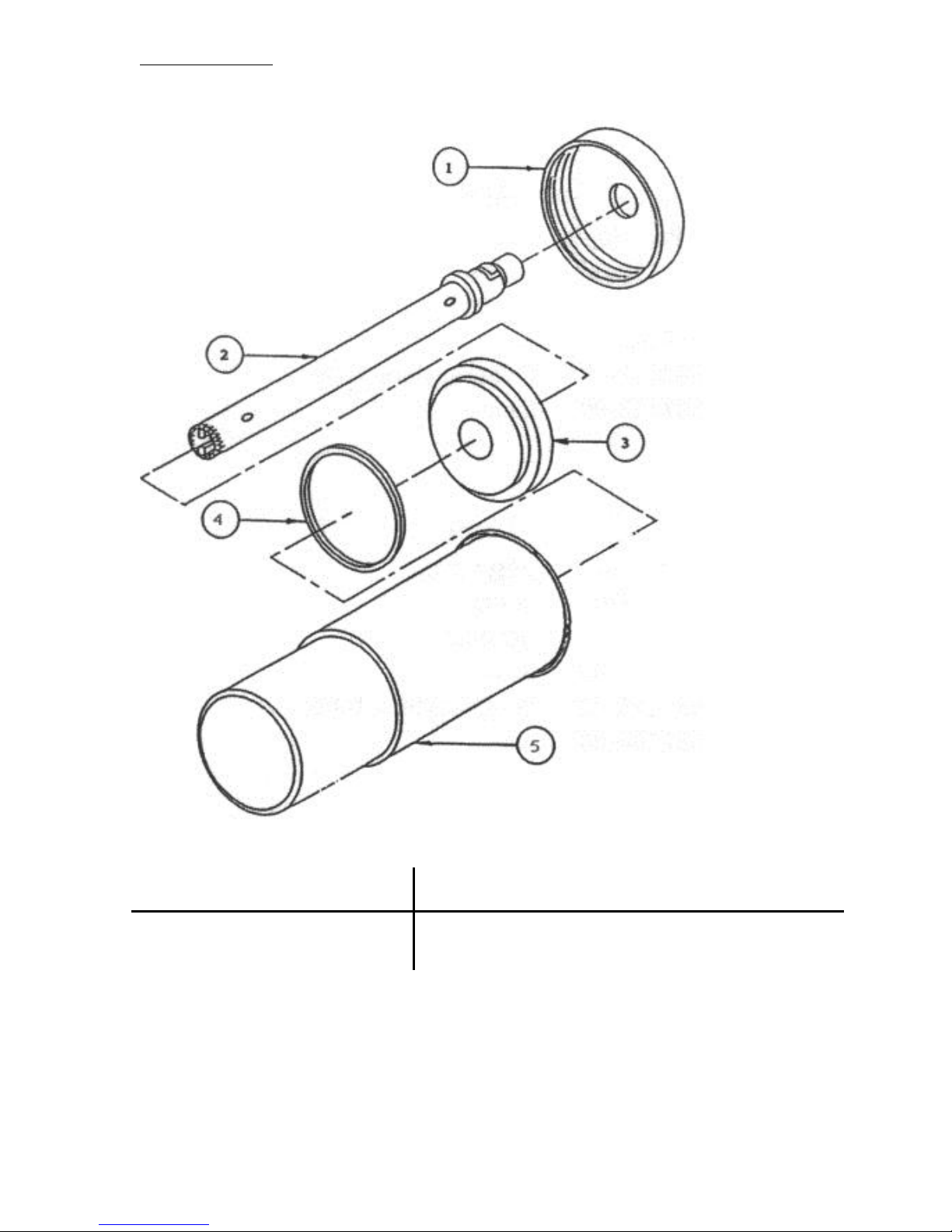
PRO Sealed Chamber Index: Drawings and Part list
Part
Number
Size
ml
Vol.
ml
Cover
Shaft
Assembly
Polypropylene
tube
Cage
Seal
(1)
(2)
(3)
(4)
(5)
15-32005
5
0.2-3
14-01150
02-05075
11-03050
11-02053
14-21051
15-32010
16
0.5-11
14-01150
02-07095
11-03100
11-02103
14-21151
15-32015
19
0.5-13
14-01150
02-07120
11-03150
11-02153
14-21151
15-32050
50
5-40
14-01500
02-10105
11-03500
11-02503
14-21501
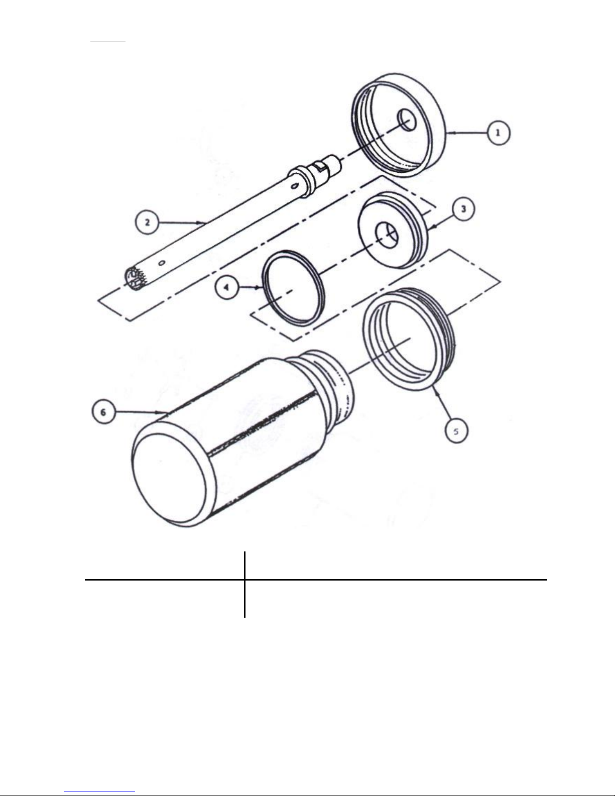
ST Series:
Use the drawing below to assist with the sealed chambers listed.
(5ml, 16ml, 19ml, and 50ml)
Page 30
30
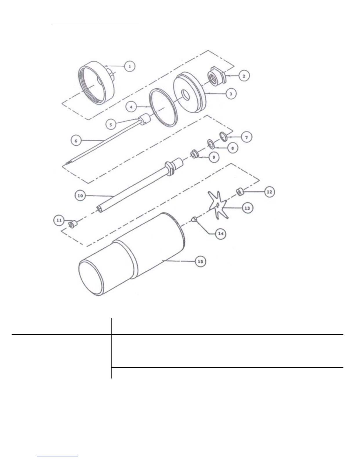
Stainless Steel:
Part Number
Size
ml
Vol.
ml
Cover
Shaft
Assembly
Plug
Gasket
S.S.
Chamber
(1)
(2)
(3)
(4)
(5)
15-02070-10
70
10-65
14-01500
02-10115
14-11701
99-00022
11-00700
15-02600-20
600
40-500
14-01600
02-20150
14-11601
99-00021
11-00600
15-02600-30
600
40-500
14-01600
02-30150
14-11601
99-00021
11-00600
15-081200
1.2L
100-1L
14-33120
02-70150
N/A
N/A
11-00120
Use the drawing below to assist with the sealed chambers listed
(600 ml)
Page 31
31
Stainless Steel with Blade:
Part
Number
Size
ml
Vol.
ml
Cover
Insert
Plug
Gasket
Rotor
Collar
Rotor
Shaft
“O” Ring
Washer
(1)
(2)
(3)
(4)
(5)
(6)
(7)
(8)
15-09070
70
10-65
14-02700
N/A
14-02701
99-00022
07-00150
05-02115
99-05016
99-03302
15-09600
600
40-500
14-02600
14-00003
14-12601
99-00021
07-00150
05-02150
99-05016
99-03302
Upper
Bearing
Tube and
Collar
Rulon
Bearing
Blade
Collar
Rotor
Blade
Acorn Nut
S.S.
Chamber
(9)
(10)
(11)
(12)
(13)
(14)
(15)
03-10001
08-02115
03-12187
07-00003
04-02001
99-22049
11-00700
03-10001
08-02150
03-12187
07-00003
04-02002
99-22049
11-00600
Use the drawing below to assist with the sealed chambers listed.
(600ml)
Page 32
32
Glass:
Part Number
Size
ml
Vol.
ml
Cover
Shaft
Assembly
Plug
Gasket
Adapter
Glass
Chamber
(1)
(2)
(3)
(4)
(5)
(6
15-12473-20
473
30-450
14-01600
02-20115
14-11001
99-00021
14-00002
11-01470
15-12473-30
473
30-450
14-01600
02-30115
14-11001
99-00021
14-00002
11-01470
15-12946-20
946
50-800
14-01600
02-20150
14-11001
99-00021
14-00002
11-01940
15-12946-30
946
50-800
14-01600
02-30150
14-11001
99-00021
14-00002
11-01940
Use the drawing below to assist with the sealed chambers listed.
(473ml and 946ml)
Page 33
33
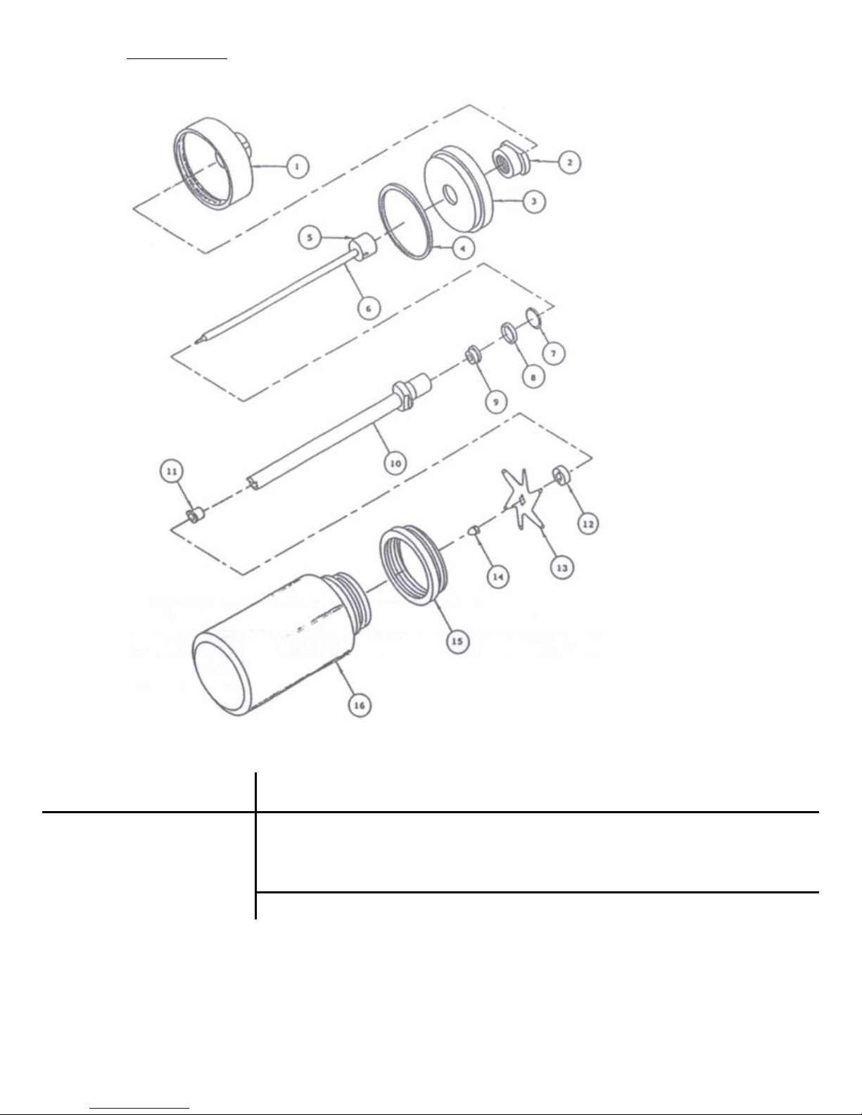
Glass Blade:
Part
Number
Size
ml
Vol.
ml
Cover
Insert
Plug
Gasket
Rotor
Collar
Rotor
Shaft
“O” Ring
Washer
(1)
(2)
(3)
(4)
-(5)-
-(6)-
(7)
(8)
15-19473
473
50-450
14-02600
14-00003
14-12001
99-00021
07-00150
05-02150
99-05016
99-03302
15-19946
946
100-800
14-02600
14-00003
14-12001
99-00021
07-00150
05-02150
99-05016
99-03302
Upper
Bearing
Tube and
Collar
Rulon
Bearing
Blade
Collar
Rotor
Blade
Acorn Nut
Adapter
Glass
Chamber
(9)
-(10)-
(11)
(12)
(13)
(14)
(15)
(16)
03-10001
08-02150
03-12187
07-00003
04-02002
99-22049
14-00002
11-01470
03-10001
08-02150
03-12187
07-00003
04-02002
99-22049
14-00002
11-01940
Use the drawing below to assist with the sealed chambers listed.
(473ml and 946ml)
 Loading...