


Proscend
Media Converter
500
User Manual
Version 1.00

500 Media Converter User Manual Version 1.00
2
Table of Contents
1
DESCRIPTIONS ................................................................................................................................................... 2
1.1
FEATURES ............................................................................................................................................................ 2
1.1.1
Ethernet over E1 converter .......................................................................................................................... 2
1.1.2
Ethernet over Serial converter ..................................................................................................................... 2
1.2
SPECIFICATION ..................................................................................................................................................... 2
1.3
APPLICATIONS ...................................................................................................................................................... 4
2
GETTING TO KNOW ABOUT THE MEDIA CONVERTER ......................................................................................... 5
2.1
FRONT PANEL ....................................................................................................................................................... 5
2.2
REAR PANEL ......................................................................................................................................................... 6
2.3
CONSOLE CABLE ................................................................................................................................................... 7
2.4
POWER CONNECTION ............................................................................................................................................ 7
2.5
RESET BUTTON ..................................................................................................................................................... 8
2.6
PROTECTIVE EARTH (FRAME GROUND) TERMINAL ....................................................................................................... 8
3
CONFIGURE PROSCEND MEDIA CONVERTER 500 ............................................................................................... 9
3.1
SETUP ............................................................................................................................................................. 12
3.1.1
INTERFACE ................................................................................................................................................. 13
3.1.2
MODE ........................................................................................................................................................ 14
3.1.3
E1 .............................................................................................................................................................. 15
3.1.3.1 Channel .............................................................................................................................................................16
3.1.3.2 Code ..................................................................................................................................................................19
3.1.3.3
AIS .....................................................................................................................................................................20
3.1.3.4 Build_outs .........................................................................................................................................................21
3.1.4 ETHERNET ................................................................................................................................................. 22
3.1.4.1 Auto ..................................................................................................................................................................23
3.1.4.2 Duplex ...............................................................................................................................................................24
3.1.4.1
Speed ................................................................................................................................................................25
3.1.5 Serial ......................................................................................................................................................... 26
3.1.5.1 Interface ............................................................................................................................................................ 27
3.1.5.2
Clock ................................................................................................................................................................. 27
3.1.5.3 Data ..................................................................................................................................................................28
3.1.5.4 RTS ....................................................................................................................................................................28
3.1.5.5
CTS ....................................................................................................................................................................29
3.1.5.6 DSR ...................................................................................................................................................................30
3.1.5.7
DCD ...................................................................................................................................................................30
3.1.5.8 Delay .................................................................................................................................................................31
3.1.6 DEFAULT .................................................................................................................................................... 32
3.1.7 REBOOT ..................................................................................................................................................... 33
3.2
STATU S ........................................................................................................................................................... 34
3.2.1
Interface .................................................................................................................................................... 35
3.2.2
Current Perf ............................................................................................................................................... 36
3.2.3
Loc_statistics ............................................................................................................................................. 37
3.2.4
clear .......................................................................................................................................................... 39
3.3
SHOW ............................................................................................................................................................. 40
3.3.1
System ....................................................................................................................................................... 41

500 Media Converter User Manual Version 1.00
3
3.3.2 Script ......................................................................................................................................................... 42
3.4
REBOOT .......................................................................................................................................................... 43
3.5
DIAG ............................................................................................................................................................... 44
3.5.1
LoopBack Test ............................................................................................................................................ 45
3.5.2
Ber t Te s t .................................................................................................................................................... 46
3.6
UPGRADE ....................................................................................................................................................... 48
3.7
EXIT ................................................................................................................................................................ 50
APPENDIX A.
TECHNICAL INFORMATION .............................................................................................................51
APPENDIX B.
TERMINOLOGY ...............................................................................................................................56
APPENDIX C.
INTERFACE PARAMETER TABLE ....................................................................................................... 57
APPENDIX D.
CONSOLE CABLE .............................................................................................................................58
APPENDIX E.
E1 BALANCED CABLE ......................................................................................................................59
APPE N D I X F.
E1 UNBALANCED CABLE .................................................................................................................60
APPENDIX G.
SERIAL INTERFACE PIN ASSIGNMENTS ............................................................................................61
APPENDIX H.
V.35 DB25(M) TO M.34(F) ADAPTOR CABLE ....................................................................................63
APPENDIX I.
X.21 DB25(M) TO DB15(F) ADAPTOR CABLE ...................................................................................66
APPENDIX J.
ETHERNET CABLE ............................................................................................................................68


500 Media Converter User Manual Version 1.00
2
1
1
DDeessccrriippttiioonnss
11..1
1
FFeeaattuurreess
11..11..1
1
EEtthheerrnneett oovveerr EE11 ccoonnvveerrtteerr
The Ethernet over E1 converter offers a channelized E1 and 10/100Base-T interface conversion. It can
provide the user with Ethernet over E1 conversion enabling the user to transport Ethernet data over an E1
link.
It converts the Ethernet data into E1 frame format for transmission over the existing TDM (E1) links and then
re-converts the E1 back into Ethernet data the far-end terminal. The device can effectively utilize the
redundant bandwidth of telecom operators existing TDM network to transport Ethernet data with low
investment. It can enable you to do as:
(1) Bridging Ethernet LANs over existing TDM (E1) telecom network
(2) Extending Ethernet networks utilizing TDM (E1) landline based telecom infrastructure
Using telecom network of E1s/PDH/SDH microwave etc. carrying E1s to transport Ethernet data
11..11..2
2
EEtthheerrnneett oovveerr SSeerriiaall ccoonnvveerrtteerr
The Ethernet over Serial converters connect serial based equipment across an Ethernet network.
Serial data sent and received on serial ports on the serial to Ethernet adapter are encapsulated in
Ethernet packets in a manner that can best fit the type of data being transported. It can enable you to do as:
(1) Serial cable replacement using Ethernet
(2) Bridging Ethernet LANs over ex isti ng Seri al net wor k
(3) A pair of this device can offer a cost effective solution for using existing V.35 leased lines for the
transparent Ethernet service
.
11..2
2
SSppeecciiffiiccaattiioonn
E1 (G.703) interface
• Framing : Unframed/PCM30/PCM31
• Bit rate : 2048 Mbps (Full-Duplex)
• Line code : AMI/HDB3
• Connector : BNC or RJ-48C
• Line impedance : unbalanced 75 ohm(BNC) for coaxial cable or balanced 120 ohm(RJ-48C) for twisted pair
• Complies with ITU-T G.703, G.706, G.732 and G.823

500 Media Converter User Manual Version 1.00
3
• Sending high electric level : ±2.37V for Coaxial Pair 75 ohm
3.00V for Symmetrical Pair 120 Ohm
Sending low electric level : 0V±0.1V
• Receiving electric level: 0~-43dB
• CRC Check : CRC-4 or Non CRC
Serial (V.35) interface
• Connection: DB-25(F)
• Connection: M.34 (Optional)
• Support RS-530, V.35 or V.36/X.21
Ethernet interface
• 10/100Mpbs Half/Full Duplex, Auto-sensing, Auto-Crossover
• Up to 2048 MAC address learning
• Connection: RJ-45 for Ethernet cable
Management
• Configuration with 4 keypads and 16 x 2 LCD display
• Console port (RJ45, RS232C)
• Support firmware upgradeable through console port
• LED Indicator : PWR, ALM TST; E1 SER ETH for CSU/DSU
Loopback Tests & Bert Test
• CSU Loopback
• DSU Loopback
• Build-in 2047 Test pattern & BER Tester
Clock Mode
• Internal Clock
• External Clock
Physical/Electrical
• AC/DC adaptor Input: 100~240VAC @ 50~60Hz / 5VDC 2A
• Power Consumption: 12W Max
• Operation temperature: 0 to 50°C
• Humidity: Up to 95% (non-condensing)

500 Media Converter User Manual Version 1.00
4
11..3
3
AApppplliiccaattiioonnss
Media
Converter 500
Media
Converter 500
INTERNET
Proscend
NTU
router
Proscend
NTU
Proscend
NTU
Proscend
NTU
router
Proscend
NTU
Proscend
NTU

500 Media Converter User Manual Version 1.00
5
2
2
GGeettttiinngg ttoo kknnooww aabboouutt tthhee MMeeddiiaa CCoonnvveerrtteerr
This section will introduce hardware of the Media Converter.
22..1
1
FFrroonntt PPaanneell
The front panel contains LEDs which show status of the device.
LED status description on front panel:
LED
Color
Action
Description
PWR
Green
On Power is on.
Off
Power is off.
ALM
Red
On
System loss.
Off
System is working normally
TST
Yellow
On System is testing for connection.
Off System is working normally
CSU
E1
Green /
Red
Green: Sync
Red: No Sync
SER Green /
Red
Green: Sync
Red: No Sync
ETH
Green /
Red
Green: Sync
Red: No Sync
DSU
E1
Green /
Red
Green: Sync
Red: No Sync
SER
Green /
Red
Green: Sync
Red: No Sync
ETH Green /
Red
Green: Sync
Red: No Sync

500 Media Converter User Manual Version 1.00
6
22..2
2
RReeaarr PPaanneell
The rear panel of Proscend Media Converter 500 is where all of the connections are made.
!
The reset button can be used only in one of two ways.
(1) Press the Reset Button for one second will cause system reboot.
(2) Pressing the Reset Button for four seconds will cause the prod uct loading the factor y default setting
and losing all of yours configuration. When you want to change its configuration but forget the user name
or password, or if the pr oduc t is havi ng prob lem s c onnecting to the Internet and you want to conf igure it
again clearing all configurations, press the Reset Button for four seconds wit h a paper clip or sharp
pencil.

500 Media Converter User Manual Version 1.00
7
22..3
3
CCoonnssoollee CCaabbllee
Connect the RJ-45 jack of the console cable to the console port of the EFM modem. Connect the DB-9 female
end to a serial port( COM1 , COM2 or other COM port) of your computer.
The wiring diagram of console cable is as following:
The pin assignment of RJ-45 modular jack on the console cable:
Pin Number
Abbrev.
Description
Figure
1
DSR
DCE ready
1 8
1 8
Top View
Front View
2
DCD
Received Line Signal Detector
3
DTR
DTE ready
4
GND
Signal Ground
5
RXD
Received Data
6 TXD Transmitted Data
7
CTS
Clear to Send
8
RTS
Request to Send
22..4
4
PPoowweerr ccoonnnneeccttiioonn
Make sure you are using the correct power source as the AC/DC adaptor. Inset the female en d of power
adaptor’s cord i nto the power receptacle on the rear panel. Conn ect the power adaptor to an appropr iate
power source.

500 Media Converter User Manual Version 1.00
8
22..5
5
RReesseett BBuuttttoonn
The reset button can be used only in one of two ways.
(1) Press the Reset Button for two second will cause system reboot.
(2) Press ing the Reset Button for eight sec onds will cause the prod uct loading the factory default se tting
and losing all of yours configur ation. W hen you want to change its c onfiguration but f orget the user nam e or
password, or if the product is hav ing problems connecting to the Internet and you want to configure it again
clearing all configurations, press the Reset Button for eight seconds with a paper clip or sharp pencil.
22..6
6
PPrrootteeccttiivvee EEaarrtthh ((FFrraammee GGrroouunndd)) tteerrmmiinnaall
The marked lug or terminal should be connected to the building protective earth bus.
The function of protective ear th does not serve the purpose of providing protection aga inst electrical shock ,
but instead enhances s urge suppression on the D SL lines for installations where suitable bonding f acilities
exist.
The connector type is M3 machine screw.
500 Media Converter User Manual Version 1.00
9
3
3
CCoonnffiigguurree PPrroosscceenndd MMeeddiiaa CCoonnvveerrtteerr 550000
Proscend Media Converter 500 presents a configuration system for users to modify their own media
converters. There are two methods to configure Proscend Media Converter 500:
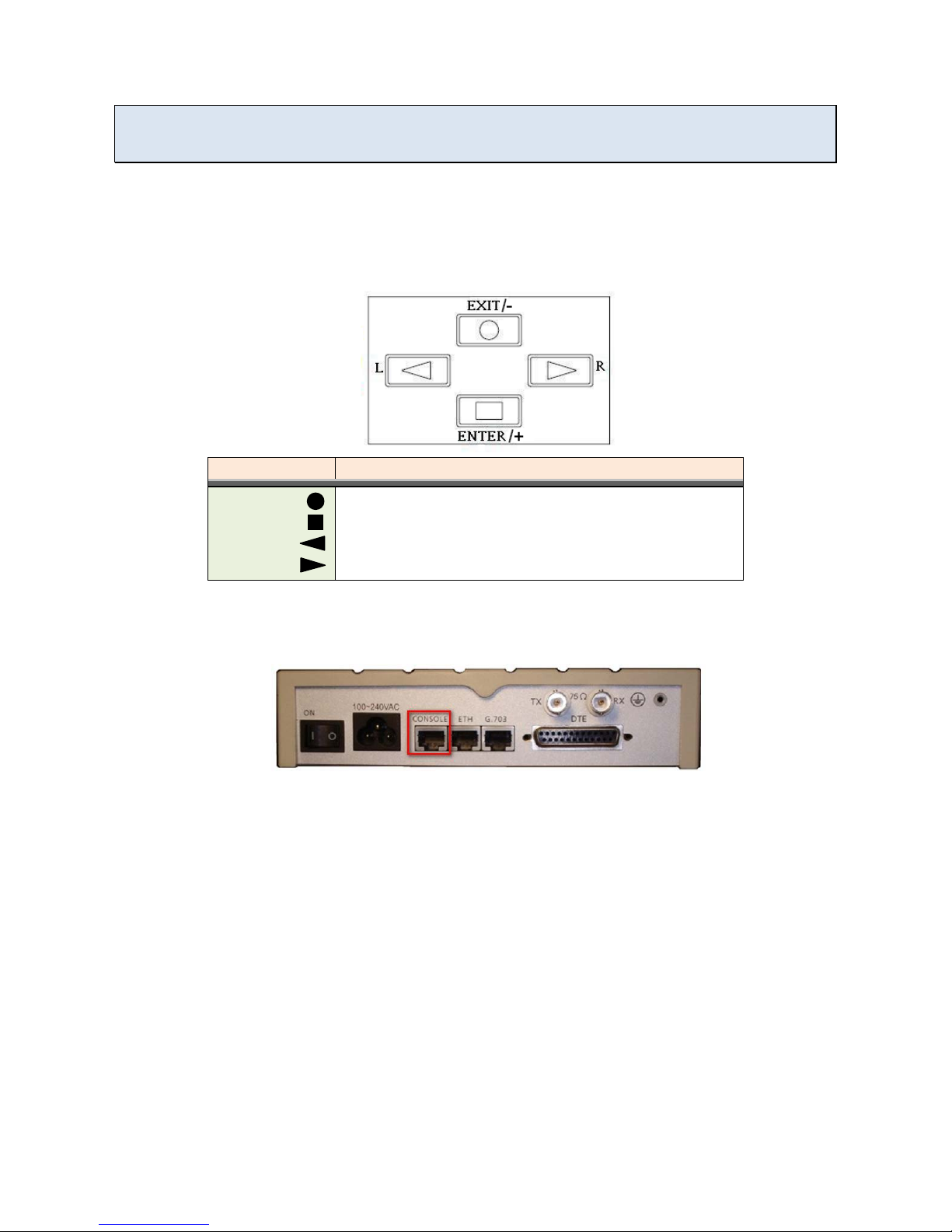
1. By key pad
Users will be able to set a media converter up by the key pad on the right-hand side of a media
converter’s front panel. The following figure shows how the key pad looks like.
Key Pad
Description
Exit/-
Return to previous configuration menu.
Enter/+
Skip to next configuration menu or configure this item.
L
Select other parameter in the same level menu.
R
Select other parameter in the same level menu.
2. By console
The other way to contr ol th e media con verter is b y a console por t in the back of the convert er. (Please
check the figure below to see the console port’s location.)
Once a user connects the converter to his or her computer, he or she can browse the configuration
system by a terminal emulation program, such as, Hyper Terminal. (In this user manual, Tera term is the
main application used.)
The following instr uctions guide users to ac cess Proscend Media Convert er 500 configuration system
through a terminal.

500 Media Converter User Manual Version 1.00
10
Step 1. Open a terminal and change its baud rate to 115200.
Step 2. Press space to allow the terminal to show login messages.
Step 3. The default user name is “admin” and its corresponding password is “admin”.
Step 4. Once a user logs in, he or she will see the main menu as the following figure. Then, the user
can change the converter’s setting with this configuration system.
In Proscend Media Con verter 500 conf iguration s ystem, there are s even major options: setup, s tatus, show,
reboot, diagnosis, upgrad e and exit. W ith thes e options, users are a ble to manage the ir converters, check
their status and upgrade their f irmware versions. T he following sections dem onstrate users how to co ntrol
their converters by key pad and by console.

500 Media Converter User Manual Version 1.00
11
Main Menu
SETUP
STAUS
SHOW
REBOOT
DIAG
UPGRADE
EXIT
Interface
Mode
E1
Ethernet
/Serial
Default
Reboot
Interface
Current
Perf
Loc_Statistics
Clear
System
Script
LoopBack
BerTest
Kernel
FPGA

500 Media Converter User Manual Version 1.00
12
33..1
1
SSEETTUUPP
Main Menu
SETUP
STAUS
SHOW
REBOOT
DIAG
UPGRADE
EXIT
Interface
Mode
E1
Ethernet
/Serial
Default
Reboot
Interface
Current
Perf
Loc_Statistics Clear
System Script
LoopBack
BerTest
Kernel
FPGA
In “SETUP”, users are allowed to change media converters’ configurations, such as, interface, mode, E1
settings, Ethernet settings, loading the default settings, and reboot the converter. In this section, a brief
description will be given for each available setup.
Choose “setup” in the main menu and users will find out more options as the following photo.

500 Media Converter User Manual Version 1.00
13
33..11..1
1
IINNTTEERRFFAACCEE
Users are able to change the in terface of m edia converters b y “Interface” function. There are two interface
options available for the converter: “ETH over E1” and “Serial over E1”.
Note: Choose “ETH over E1” to enable Ethernet parameter setups. Choose “Serial over E1” to enable Serial
parameter setups.
From console
Click “tab” on the key board to select an interface option. Press “Enter” to decide which interface the
converter should use.
From key pad
MEDIA CONVERTER
=ETH over E1=
SYSTEM
SETUP
SETUP
INTERFACE
* INTERFACE *
ETH over E1
* INTERFACE *
Serial over E1
ENTER
ENTER
LEFT / RIGHT
LEFT / RIGHT
ENTER
Note: Please make sure to reboot the converter after the configuration is completed.

500 Media Converter User Manual Version 1.00
14
33..11..2
2
MMOODDEE
“Mode” allows users to choose a clock m ode: INCLK or EXT CLK. The clock mode is set according to the
clock mode of the device in the other side of DSL line.
From console
Use “tab” to change the clock mode and press “enter” to save the final decision.
From key pad
MEDIA CONVERTER
=ETH over E1=
SYSTEM
SETUP
SETUP
MODE
* SHDSL MODE *
INTCLK
* SHDSL MODE *
INTCLK
ENTER ENTER
LEFT / RIGHT
LEFT / RIGHT
ENTER
Mode Description
INTCLK Internal Clock. If the equipment in the other side of E1 is set to external clock, the converter
should be set to internal clock.
EXTCLK
External Clock. If the equipment in the other side of E1 is set to internal clock, the converter
should be set to external clock.

500 Media Converter User Manual Version 1.00
15
33..11..3
3
EE11
“E1” includes all E1 parameters, such as, channel, code, AIS, and build_outs.
From console
Choose “E1” to enable more E1 parameter settings.
From key pad
MEDIA CONVERTER
=ETH over E1=
SYSTEM
SETUP
SETUP
E1
ENTER
ENTER ENTER

500 Media Converter User Manual Version 1.00
16
33..11..33..11
CChhaannnneell
“Channel” is one of E1 parameters. In this function, users are allowed to configure E1 interface channel with
framer and the corresponding slot number.
From console
Framer Slot Number First Slot
PCM31
FAS
1 to 31
1 to 31
PCM31C
FAS+CRC4
1 to 31
1 to 31
PCM30 FAS+CAS 1 to 30 1 to 31 (can’t use 16)
PCM30C
FAS+CAS+CRC4
1 to 30
1 to 31 (can’t use 16)
FULL
UNFRAMED
(Note: For detail information about the terminologies in the table above, please check A-1.)

500 Media Converter User Manual Version 1.00
17
Channel
Number of slots
1st slot
FULL
(UNFRAMED)
PCM31 PCM31C
31
1
30
1~2
29
1~3
28
1~4
27
1~5
26
1~6
25 1~7
24
1~8
23 1~9
22
1~10
21
1~11
20
1~12
19
1~13
18
1~14
17 1~15
16
1~16
15 1~17
14
1~18
13
1~19
12
1~20
11
1~21
10
1~22
9
1~23
8
1~24
7
1~25
6
1~26
5
1~27
4
1~28
3
1~29
2
1~30
1 1~31
PCM30 PCM30C
30
1
29
1~2
28
1~3
27
1~4
26
1~5
25
1~6
24
1~7

500 Media Converter User Manual Version 1.00
18
23
1~8
22
1~9
21
1~10
20
1~11
19
1~12
18
1~13
17 1~14
16
1~15
15
1~15,17
14
1~15,17~18
13
1~15,17~19
12
1~15,17~20
11
1~15,17~21
10
1~15,17~22
9
1~15,17~23
8
1~15,17~24
7
1~15,17~25
6
1~15,17~26
5 1~15,17~27
4
1~15,17~28
3
1~15,17~29
2 1~15,17~30
1
1~15,17~31
From key pad
MEDIA CONVERTER
=ETH over E1=
SYSTEM
SETUP
SETUP
E1
ENTER
ENTER
LEFT / RIGHT
To choose
ENTER
ENTER
SETUP
CHANNEL
* E1 CHANNEL *
FULL
* E1 CHANNEL *
PCM31
* E1 CHANNEL *
PCM31C
* E1 CHANNEL *
PCM30
* E1 CHANNEL *
PCM30C
ENTER
* SLOT NUMBER *
(NUMBER)
* APPLY CHANGES *
YES/NO
ENTER
* APPLY CHANGES *
OK!
ENTER
EXIT

500 Media Converter User Manual Version 1.00
19
33..11..33..22
CCooddee
“Code” function prov ides two options for users . Users are allowed to choice either “HDB3” or “AMI”. For
detail information, please reference to A-2
.
From console
From key pad
MEDIA CONVERTER
=ETH over E1=
SYSTEM
SETUP
SETUP
CODE
ENTER
ENTER
LEFT / RIGHT
LEFT / RIGHT
ENTER
ENTER
SETUP
CODE
* E1 CODE *
HDB3
* E1 CODE *
AMI

500 Media Converter User Manual Version 1.00
20
33..11..33..33
AAIISS
“Ais” function can be turned on or off in Proscend Media Converter 500. For AIS details, please check A-3
.
From console
From key pad
MEDIA CONVERTER
=ETH over E1=
SYSTEM
SETUP
SETUP
E1
ENTER
ENTER
ENTER
SETUP
AIS
LEFT/RIGHT
* E1 AIS *
On/Off

500 Media Converter User Manual Version 1.00
21
33..11..33..44
BBuuiilldd__oouuttss
“Build_outs” presents two i mpedance options f or E1 interface, th e unbalanced E1 at 75ohms and ba lanced
E1 at 120 ohms.
From console
From key pad
MEDIA CONVERTER
=ETH over E1=
SYSTEM
SETUP
SETUP
E1
ENTER
ENTER
ENTER
SETUP
BUILD OUTS
LEFT/RIGHT
* E1 BUILD OUTS *
120 ohm
* E1 BUILD OUTS *
75 ohm

500 Media Converter User Manual Version 1.00
22
33..11..4
4
EETTHHEERRNNEETT
“Ethernet” sect ion presents more Ethern et parameter s ettings. By enter “Ethernet” in “Setup” m enu, users
are able to configure Ethernet parameters.
From console
From key pad
MEDIA CONVERTER
=ETH over E1=
SYSTEM
SETUP
SETUP
ETHERNET
ENTER
ENTER
Once users enter ETHERNET menu, they will find out three Ethernet parameters: “Auto”, “Duplex” and
“Speed”. The following sections will provide instructions for these parameters.

500 Media Converter User Manual Version 1.00
23
33..11..44..11
AAuuttoo
“Auto” allows user s to setup the rest of Ethernet parameters autom atically. If “Auto” mode is enabled, th e
other two parameters, “Duplex” and “Speed”, will not be effective.
From console
From key pad
MEDIA CONVERTER
=ETH over E1=
SYSTEM
SETUP
SETUP
ETHERNET
ENTER
ENTER ENTER
SETUP
AUTO
LEFT/RIGHT
* AUTO *
Enable
/
Disable
Note: Setting “Auto” mode to disable will enable duplex and speed options.

500 Media Converter User Manual Version 1.00
24
33..11..44..22
DDuupplleexx
Choose “Duplex” from the Ethernet menu and press enter to setup duplex.
If “Auto” mode is enabled, the user will see the following message.
From console
From key pad
MEDIA CONVERTER
=ETH over E1=
SYSTEM
SETUP
SETUP
ETHERNET
ENTER
ENTER
ENTER
SETUP
DUPLEX
ENTER
* DUPLEX *
ETH AUTO CONFIG
If auto mode is disabled, use “tab” to choose duplex mode. (Full-Duplex or Half-Duplex)
From console
From key pad
MEDIA CONVERTER
=ETH over E1=
SYSTEM
SETUP
SETUP
ETHERNET
ENTER
ENTER
ENTER
SETUP
AUTO
LEFT/RIGHT
* DUPLEX *
Full-Duplex
/
Half-Duplex

500 Media Converter User Manual Version 1.00
25
33..11..44..11
SSppeeeedd
Choose “Speed” from the Ethernet menu and press enter to setup speed.
If auto mode is enabled, the user will see the following message.
From console
From key pad
MEDIA CONVERTER
=ETH over E1=
SYSTEM
SETUP
SETUP
ETHERNET
ENTER
ENTER
ENTER
SETUP
SPEED
ENTER
* SPEED *
ETH AUTO CONFIG
If auto mode is disabled, use “tab” to choose speed mode. (100M or 10M)
From console
From key pad
MEDIA CONVERTER
=ETH over E1=
SYSTEM
SETUP
SETUP
ETHERNET
ENTER ENTER ENTER
SETUP
SPEED
LEFT/RIGHT
* SPEED *
100M
/
10M

500 Media Converter User Manual Version 1.00
26
33..11..5
5
SSeerriiaall
To enable “Serial” parameter setups, ple ase make sure change “SETUP >> INTERFACE” option to “Serial
over E1” first.
From console
From key pad
MEDIA CONVERTER
=ETH over E1=
SYSTEM
SETUP
SETUP
INTERFACE
ENTER
ENTER ENTER
* INTERFACE *
Serial over E1
Then, users will see eight parameter options as the following photography.

500 Media Converter User Manual Version 1.00
27
33..11..55..11
IInntteerrffaaccee
“Interface” consists of two options : V.35 an d RS-530 (x.21). Choose either V.35 or RS-530(x .21) hardware
standard for Serial interface.
From console
From key pad
MEDIA CONVERTER
=Serial over E1=
SYSTEM
SETUP
SETUP
SERIAL
ENTER ENTER
ENTER
SETUP
INTERFACE
ENTER
* INTERFACE *
V35 /RS530
33..11..55..22
CClloocckk
“Clock” f unction allows users to set clock polarit y as “Normal” or “Inverse”. “Normal”, which is the default
setting, means that data is sent on the positive transition of the clock; in contrast to it, “Inverse” sends data on
the negative clock transition.
From console

500 Media Converter User Manual Version 1.00
28
From key pad
MEDIA CONVERTER
=
Serial over E1=
SYSTEM
SETUP
SETUP
SERIAL
ENTER ENTER
ENTER
SETUP
CLOCK
ENTER
* SERIAL CLOCK *
Normal / Inverse
33..11..55..33
DDaattaa
“Data” function includes two selections: “Normal” and “Inverse”.
From console
From key pad
MEDIA CONVERTER
=
Serial over E1=
SYSTEM
SETUP
SETUP
SERIAL
ENTER
ENTER ENTER
SETUP
DATA
ENTER
* SERIAL DATA *
Normal / Inverse
33..11..55..44
RRTTSS
“RTS” means “Request to Send” signal and c onsists of two o ptions: ON a nd from _dte. “ON” option means
RTS signal is always forced high (on, positive voltage or SPACE). “from_dte” means the signal will follow the
DTE’s condition. The default RTS setting is “ON”.

500 Media Converter User Manual Version 1.00
29
From console
From key pad
MEDIA CONVERTER
=
Serial over E1=
SYSTEM
SETUP
SETUP
SERIAL
ENTER
ENTER ENTER
SETUP
RTS
ENTER
* SERIAL RTS *
on / from_dte
33..11..55..55
CCTTSS
“CTS” represents “Clear to Send” si gnal and includes three setup options: “from_rts”, “on”, and “off”. “on”
options means CTS signal is always forced to high. In contrast to “on”, “off” means the signal is always set t o
low. In addition, “from_rts” means the signal follows RTS condition. The default setting is “from_rts”.
From console
From key pad
MEDIA CONVERTER
=
Serial over E1=
SYSTEM
SETUP
SETUP
SERIAL
ENTER ENTER ENTER
SETUP
CTS
ENTER
* SERIAL CTS *
from_rts / on / off

500 Media Converter User Manual Version 1.00
30
33..11..55..66
DDSSRR
“DSR” implies “Data Set Ready” signal and it can be set in three modes: “on”, “off”, “from_dtr”. “On”
illustrates DSR signal is always high; in opposite to it, “off” presents the s ignal is alwa ys low. “from_dtr” will
set DSR to follow DTR (Data Terminal Ready) condition. The default DSR setup is “on”.
From console
From key pad
MEDIA CONVERTER
=
Serial over E1=
SYSTEM
SETUP
SETUP
SERIAL
ENTER
ENTER
ENTER
SETUP
DSR
ENTER
* SERIAL DSR *
on / off / from_dtr
33..11..55..77
DDCCDD
“DCD”, Data Carrier Detect, function provides two choices: “on” and “off”. DCD signal is alwa ys high if DCD
is set as “on” and DCD signal is always low if the setting is “off”. The default setting is “on”.
From console

500 Media Converter User Manual Version 1.00
31
From key pad
MEDIA CONVERTER
=Serial over E1=
SYSTEM
SETUP
SETUP
SERIAL
ENTER
ENTER
ENTER
SETUP
DCD
ENTER
* SERIAL DCD *
on / off
33..11..55..88
DDeellaayy
“Delay” functio n is us ed t o del a y CTS in order to follow RTS. Users are able to set the value of “delay” from
0 to 3 milliseconds. The default setting is 3 milliseconds.
From console
From key pad
MEDIA CONVERTER
=Serial over E1=
SYSTEM
SETUP
SETUP
SERIAL
ENTER
ENTER ENTER
SETUP
DELAY
ENTER
* SERIAL DELAY *
0 ~ 3

500 Media Converter User Manual Version 1.00
32
33..11..6
6
DDEEFFAAUULLTT
“Default” allows users to restore Media Converter 500 factory setups.
From console
Choose “Default” from the m enu. Key in “y” and press enter to restore default settings. Key in “n” and
press enter to cancel this option.
If the user chooses to load default settings, the user will see a confirm message as the following display.
Please make sure the display returns to the main menu before processing any further actions.

500 Media Converter User Manual Version 1.00
33
From key pad
MEDIA CONVERTER
=ETH over E1=
SYSTEM
SETUP
SETUP
ETHERNET
ENTER
ENTER
LEFT/RIGHT
* LOAD DEFAULT *
YES / NO
33..11..7
7
RREEBBOOOOTT
“Reboot” accepts users to r eboot the conv erter without po wering down and up the converter. Pleas e make
sure reboot the converter after users complete with their modifications.
From console
From key pad
MEDIA CONVERTER
=ETH over E1=
REBOOT
SYSTEM
ENTER

500 Media Converter User Manual Version 1.00
34
33..2
2
SSTTAATTUUSS
Main Menu
SETUP
STAUS
SHOW
REBOOT
DIAG
UPGRADE
EXIT
Interface
Mode
E1
Ethernet
/Serial
Default
Reboot
Interface
Current
Perf
Loc_Statistics
Clear
System Script
LoopBack
BerTest
Kernel FPGA
In “Status” menu, there are four status functions: “Interface”, “Current Perf”, “Loc_statistics”, and “clear”.
In this section, users are able to explore interface status, current connection performance and statistics
information. In addition , if users would like to reset the statistics infor mation, they can remove a ll records
with “clear” function.

500 Media Converter User Manual Version 1.00
35
33..22..1
1
IInntteerrffaaccee
“Interface” shows the i nterface status, such as, STU type, interfac e type, data rate, etc. It refreshes the
information every 2 secon ds automatically. To escape this window, press “CTRL-c”; other wise, the screen
will display interface information continuously.
From console
From key pad
MEDIA CONVERTER
=ETH over E1=
SHOW
STATUS
STATUS
INTERFACE
ENTER ENTER ENTER
* INTERFACE *
ETH over E1
ENTER
STATUS
MODE
* MODE *
INTCLK / EXTCLK
ENTER
ENTER
STATUS
E1
ENTER
E1 INFORMATION
ENTER
STATUS
ETHERNET
ENTER
ETH INFORMATION

500 Media Converter User Manual Version 1.00
36
33..22..2
2
CCuurrrreenntt PPeerrff
“Current Perf” accum ulates performance data for the cur rent 15 minute interval and for the cur rent 24 hour
interval. This window will not timeout so press “CTRL-c” to exit this window.
From console
From key pad
MEDIA CONVERTER
=ETH over E1=
SHOW
STATISTICS
STATISTICS
CURRENT 15MIN
ENTER
ENTER ENTER
* E1 ES *
VALUE
ENTER
STATISTICS
CURRENT 24HR
ENTER
* E1 SES *
VALUE
* E1 UAS *
VALUE
* E1 ES *
VALUE
* E1 SES *
VALUE
* E1 UAS *
VALUE

500 Media Converter User Manual Version 1.00
37
33..22..3
3
LLoocc__ssttaattiissttiiccss
“Loc_statistics” shows perf ormance data for the previous 15 minute int erval and for the previous 24 hour
interval. Use “tab” to choose tim e interval. This window will not timeout so press “CTRL-c” to exit this
window. Each q uarter wil l store the data for the prev ious tim e interval an d the firs t line alwa ys presents the
latest data for the time in terval the user c hooses. For example, if th e user choose “15 minute” as the t ime
interval. The data of the first 15 minute interval will be shown on the first line (the line of “15 Minute”). After
the first 15 minutes, the data will be displayed in “Quarter 1” and a new data for the current 15 minute interval
will be placed on the first line.
Note: the performance monitor is capable of storing and retrieving performance information for each 24 hour
interval, up to 7 days.
From console

500 Media Converter User Manual Version 1.00
38
From key pad
MEDIA CONVERTER
=ETH over E1=
SHOW
STATISTICS
STATISTICS
CURRENT 15MIN
ENTER ENTER
ENTER
* E1 ES *
VALUE
ENTER
STATISTICS
CURRENT 24HR
ENTER
* E1 SES *
VALUE
* E1 UAS *
VALUE
* E1 ES *
VALUE
* E1 SES *
VALUE
* E1 UAS *
VALUE
QUARTER
VALUE
(1 ~ 96)
QUARTER
VALUE
(1 ~ 96)
ENTER
ENTER

500 Media Converter User Manual Version 1.00
39
33..22..4
4
cclleeaarr
“clear” represents the function to clear all statistics data. The media converter system records all data for the
statistics purpose. In order to have the latest inform ation, it is strongly suggested to use “clear” function
before starting recording data. Choose “clear” and click on “tab” to decide to clear local data or remote data.
From console
From key pad
MEDIA CONVERTER
=ETH over E1=
SHOW
STATISTICS
STATISTICS
CLEAR ALL
ENTER ENTER ENTER
* CLEAR *
YES / NO

500 Media Converter User Manual Version 1.00
40
33..3
3
SSHHOOWW
Main Menu
SETUP
STAUS
SHOW
REBOOT
DIAG
UPGRADE
EXIT
Interface
Mode
E1
Ethernet
/Serial
Default
Reboot
Interface
Current
Perf
Loc_Statistics
Clear
System Script
LoopBack
BerTest
Kernel
FPGA
In “Show” section, users are able to choose to review the system information in either table mode (System) or
script mode (Script).

500 Media Converter User Manual Version 1.00
41
33..33..1
1
SSyysstteemm
“System” presents general system information of a media converter, which includes model type, firmware
version, FPGA version, etc., in a table st yle. (Note: among all these information, it is im port to deliver the
information of firmware version and FPGA version when users request any assistance.)
From console
From key pad
MEDIA CONVERTER
=ETH over E1=
SHOW
STATUS
ENTER ENTER
SHOW
CODE VERSION
ENTER
KERNEL FPGA
2.00.2 0.06
Note: Some of information is only available in console mode.

500 Media Converter User Manual Version 1.00
42
33..33..2
2
SSccrriipptt
“Script” mode shows system information in script style. This function is only provided in console mode.
Ethernet mode
Serial mode

500 Media Converter User Manual Version 1.00
43
33..4
4
RREEBBOOOOTT
Main Menu
SETUP
STAUS
SHOW
REBOOT
DIAG
UPGRADE
EXIT
Interface
Mode
E1
Ethernet
/Serial
Default
Reboot
Interface
Current
Perf
Loc_Statistics
Clear
System
Script
LoopBack
BerTest
Kernel
FPGA
“Reboot” function presents a way to restart a media converter without switching power supply. (Note: please
make sure rebooting a media converter after configuring the converter.)
From console
From key pad
MEDIA CONVERTER
=ETH over E1=
REBOOT
SYSTEM
ENTER
ENTER
* REBOOT *
YES / NO

500 Media Converter User Manual Version 1.00
44
33..5
5
DDIIAAGG
Main Menu
SETUP
STAUS
SHOW
REBOOT
DIAG
UPGRADE
EXIT
Interface
Mode
E1
Ethernet
/Serial
Default
Reboot
Interface
Current
Perf
Loc_Statistics
Clear
System
Script
LoopBack
BerTest
Kernel
FPGA
“DIAG” is featured with two diagnosing functions: Loopback test and Bert test. Once users set up a test, the
system will run the test continuously. Only when a user cancels this setup, the system will stop running tests.
Please make sure that test setups are disabled after users collect all information they need from these tests.

500 Media Converter User Manual Version 1.00
45
33..55..1
1
LLooooppBBaacckk TTeesstt
For Loopback tes t, users are able to cho ose perf orm “CSU Loop” or “DSU Loop”. When test inform ation is
collected, please m ake sure loopback test is disabled. Also, if a user w ould like to switch between “CSU
Loop” and “DSU Loop”, please make sure to disable loopback test first.
From console
From key pad
MEDIA CONVERTER
=ETH over E1=
SYSTEM
DIAGNOSTIC
ENTER
ENTER
DIAG
LOOPBACK
ENTER
* LOOPBACK *
Disable / CSU Loop
/ DSU Loop

500 Media Converter User Manual Version 1.00
46
33..55..2
2
BBeerrtt TTeesstt
“Bert Test” is co ns is ted of f our p oss ib il ities to r un t his test: “RUN MASTER 2047”, “RUN SLAVE 2047”, “RUN
MASTER 511” and “RUN SLAVE 511”. Pl ease dis ab l e Bert test when users are done with the test.
From console
Choose “BerTest” again, to disable the t est (disable), res ynchronize the test (resync) or query information
(info) of Bert Test.
Media Converter 500 includes an internal Bit Error Rate Tester (BERT) for complete testing of local and
remote modem and the link quality without any nee d for external test equipm ent. This b uilt-in Bit Error Rate
Test generator can g enerates a standard 2047 (2
11
-1) test pattern (Pseudorando m test pattern, 2047 bits in
length). Users can quit information page anytime by “CTRL-C”.
Test Pattern 2047
Use the standard 2047 (211-1) test pattern
Time Elapsed
Show the time elapsed count
Pattern Framing
Show the linking is sync or no sync
Bit Error Count
Show the bit error counter
Refresh counter Page refresh counter

500 Media Converter User Manual Version 1.00
47
From key pad
MEDIA CONVERTER
=ETH over E1=
SYSTEM
DIAGNOSTIC
ENTER
ENTER
DIAG
BER TEST
ENTER
* BERT *
RUN MASTER 2047 /
RUN SLAVE 2047/
RUN MASTER 511/
RUN SLAVE 511
ENTER
RUN (SEC): 00000
BIT ERR: XXX
ENTER
* BERT *
RESYNC
* BERT *
DISABLE
ENTER
ENTER
RUN (SEC): 00000
BIT ERR: XXX
ENTER
* BERT *
INFO
ENTER
RUN (SEC): 00000
BIT ERR: XXX
Show these options after
running test already.
“BIT ERR” shows bit err or. If there is no error, it will show “00000”. If there is no connection built correctly, it
shows “NO SYNC”.

500 Media Converter User Manual Version 1.00
48
33..6
6
UUPPGGRRAADDEE
Main Menu
SETUP
STAUS
SHOW
REBOOT
DIAG
UPGRADE
EXIT
Interface
Mode
E1
Ethernet
/Serial
Default
Reboot
Interface
Current
Perf
Loc_Statistics
Clear
System
Script
LoopBack
BerTest
Kernel
FPGA
Upgrade function is pro vided in conso le mode with Xmodem protoc ol only. Please m ake sure your conso le
support “Xmodem” protocol before start to update the media converter. In “Upgrade”, both kernel and FPGA
can be updated.

500 Media Converter User Manual Version 1.00
49
These steps will guide user s ho w to upgra de the m edi a conv erter’s firmware with a consol e, in th is exam ple,
the console is T era term.
Step 1. Choose “Kernel” or “Fpga” option to upgrade the media converter.
Step 2. Once the option is decided, the user will see the following photograph.
Step 3. Now the user is required to send the firmware file he or she would like to update.
Step 4. If the user is failed to send a f irmware fil e in time, the system wil l terminate th is upgrade process
and show a message as the following photograph.
Step 5. Once the firmware file is uploaded successfully , the system will reboot automatically.

500 Media Converter User Manual Version 1.00
50
33..7
7
EEXXIITT
Main Menu
SETUP
STAUS
SHOW
REBOOT
DIAG
UPGRADE
EXIT
Interface
Mode
E1
Ethernet
/Serial
Default
Reboot
Interface
Current
Perf
Loc_Statistics
Clear
System
Script
LoopBack
BerTest
Kernel
FPGA
“Exit” f unction is on ly provided i n console m ode. T his func tion allows users to logou t from t he configuratio n
system.
Once the user keys in “y”, the system will log off the user.

500 Media Converter User Manual Version 1.00
51
AAppppeennddiixx AA.
.
TTeecchhnniiccaall IInnffoorrmmaattiioonn
A-1 E1 Parameter - Channel
Framing is required to recover the channelized E 1. In transparent operation, the f raming is configured as
Unframed or FU LL. In this case the G.SHDSL framer must be set to N x64 with N =32. For an y fram ing suc h
as FAS or CAS, the G.SHDSL framer must be set to E1, then the E1 fr aming here ma y be set accordingly.
The default setting is PCM31C.
Channel
Framing
PCM31 FAS
PCM31C FAS+CRC4
PCM30 FAS+CAS
PCM30C FAS+CAS+CRC4
FULL
Unframed E1
(transparent)
PCM31 and PCM31C / FAS and FAS+CRC4
FAS
0 1 2 3 4 5 6 7
8 31
Time Slot
64k 64k 64k 64k 64k 64k 64k 64k 64k 64k1408k
9 ~ 30
Maximun Data Rate 1948kbps
CAS
Also known as time slot 16 multiframing. It requires a multiframe
alignment signal to be pres ent for frame sync.
The Multiframe Alignm ent
Signal (MFAS) is inserted into the 16th t imeslot of f rame 0 of the 16-
frame
multiframe.
In CAS mode, there have 30 channels availab le for user data.
If timeslot
16 is included in the unit’s mapping, it will be disregarded.
FAS
Frame Alignment Signal use 7-bit pattern to establish and maintain frame
synchronization. The FAS word is located in timeslot 0 of frame.
In FAS
mode there have 1~31 timeslot available for use data.

500 Media Converter User Manual Version 1.00
52
PCM30 and PCM30C / FAS+CAS and FAS+CAS+CRC4
FAS
0 1 2 3 4 16
31
Time Slot
64k 64k 64k 64k 64k 64k 64k896k
17 ~ 30
CAS
5 ~ 15
704k
Data Rate (x) 960kbps
Data Rate (y) 960kbps
Maximun Data Rate = x + y = 1920kbps
CRC4
The CRC-4 checksum bits are transmitted in the outgoing E1 data
stream.
Also the received signal is checked for errors.
CRC-4 checksum cannot be sent in unframed mode.
Unframed
In this mode, user data is inserted into all 32 channels (64k x 32 =
2048k) of the E1 stream . The object of runni ng without fram
ing is to
utilize the full bandwidth of the E1 line.
UNFRAMED
0 1 2 3 4 5 6 7
8 31
Time Slot
64k 64k 64k 64k 64k 64k 64k 64k 64k 64k1408k
9 ~ 30
Maximun Data Rate 2048kbps
G.703 (E1) can su pports da ta rate of 2048kbps, so the maximum data rate of SHDSL line, connected with E1
DCEs, depends on data rate of E1, 2048kbps.
STU-C (E1)
STU-R (E1)
DTE
DTE
E1
E1 SHDSL
Frame E1
Data rate 2048
If the connection is E1 vs V.35 or V.35 vs E1, the f rame has to be us ed N x 64k . In this case, the data rate
depends on value of N. Same as above c ase, SHD SL and V35 can sup port 230 4kbps data rate (36 x 64k )
but E1 supports maximum data rate of 2048kbps (32 x 64k).

500 Media Converter User Manual Version 1.00
53
STU-C (E1)
STU-R
(V.35)
DTEDTE
V.35
E1 SHDSL
Frame N x 64 (N=1~32)
STU-C (V.35)
STU-R (E1)
DTE
DTE
E1
V.35 SHDSL
Frame N x 64 (N=1~32)
Time slot, N value, is place of data in the frame. Time Slot Number 1~31 (N=1~31) is Fractional E1 and Time
Slot Number 32 (N=32) is unframed.
Fractional E1
For fractional E1( FE1), the data rate is from 64k, N=1, to 1984k, N=31, according to the E1 frame.
If the E1 frame is PCM31(FAS) or PCM31C(FAS+CRC4), there have 1~31 available time slot for used data.
For example, if the data rate of SHDSL line set to be 512k, the time slot number is 8 and first time slot number
is 1. The frame is shown as below.
FAS
Data Data
Data Data
Data
Data Data
Data
0 1 2 3 4 5 6 7
8 31
Time Slot
64k 64k 64k 64k 64k 64k 64k 64k 64k 64k1408k
9 ~ 30
The First Time Slot setting of FAS and FAS+ CRC4 (PCM31 and PCM31C) have to follow the rule:
RULE
First Time Slot ≦ 31- Time Slot Number
First Time Slot ≦ 31- Time Slot Number
Using E1 frame of FAS+CAS or F AS+C AS+C RC4(PCM30 or PCM30C), the [FAS] will occupy Time Slot 0 and
[CAS] will occupy Time Slot 16. There have only 30 Time Slot left for data. On the other hand, the data rate
is 1920kbps (30x64Kbps).

500 Media Converter User Manual Version 1.00
54
FAS
0 1 2 3 4 16
31
Time Slot
64k 64k 64k 64k 64k 64k 64k896k
17 ~ 30
CAS
5 ~ 15
704k
The First Time Slot setting of FAS+CAS and FAS+CAS+CRC4 (PCM30 and PCM30C) have to follow the rule:
RULE
First Time Slot ≦ 30 - Time Slot Number
First Time Slot ≦ 30 - Time Slot Number
Unframed E1
Used data is inserted into all 32 channels (64Kbps x 32 = 2048Kpbs) of the E1 stream.
Data Data Data Data
Data
Data Data
Data Data
Data Data
0 1 2 3 4 5 6 7
8 31
Time Slot
64k 64k 64k 64k 64k 64k 64k 64k 64k 64k1408k
9 ~ 30
A-2 E1 Parameter – Code
HDB3 is the most popular and preferred line coding and is also the default setting.
AMI line coding is also selectable.
HDB3
In this line coding, the transmitter substitutes a deliberate bipolar violation when
excessive zeros in the data stream are detected.
The receiver recogn izes these
special violations and decodes them as zeros. This method enables the network to
minimum pulse densit y requirements.
Unless AMI is required f or your applicatio n,
HDB3 should be used whenever possible.
AMI
Alternate Mark Inversion defines pulses as a “mark,” a binary one as, as opposed to
a zero. In an E1 network connection, signals are transmitted as a sequence of one
and zero. One is sent as pulse, and zero is sent as spaces, i.e. no pulse.
Every
o
ther pulse is inverted from the pr evious pulse in polar ity, so that the signal can be
effectively transmitted. T his m eans, ho wever, that a long sequ ence of zero in da ta
stream will cause problems, since the NTU receiving the signal relies on the signal to
recover the 2048kbps clock.
A-3 E1 Parameter – AIS
AIS (Alarm Indication Signal) is a method to inform the remote connection that there is a signal or sync
problem with the E1. AIS is only valid in fr amed mode E1, not in Unframed E1. The sett ing here of AIS
enabled (on) or not (off) and is for testing with AIS. When enabled, the E1 will transmit the AIS and it should

500 Media Converter User Manual Version 1.00
55
be confirmed at the remote device (AIS indication lit). After testing, please turn AIS off.
For example 1: When ST U-R E1 RX line is drop, STU-R sends the status to STU-C via EOC or command,
and then STU-C will send AIS (Alarm Indication Signal) to DTE while AIS function is enabled.
For example 2: W hen SHDSL connection dr ops, STU -R and ST U-C both sen d AIS ( Alarm Indication Sign al)
to DTE in the same time while AIS function is enabled.
A-4 What are CSU and DSU?
A CSU/DSU (Channel Service Unit/ Data Service Un it) is a digital-interface device used to connec t a DTE
device, such as a rout er, to a digital circuit, a T1 or T 3 line). A CSU/DSU operates at the physical l ayer of
OSI model. It is also made as a separate physical product.

500 Media Converter User Manual Version 1.00
56
AAppppeennddiixx BB.
.
TTeerrmmiinnoollooggyy
Abbreviation
Meaning
AIS Alarm Indication Signal
AMI Alternate mark inversion
BERT
Bit Error Rate T esting
CAS
Channel Associated Signaling
CRC
Cyclic Redundancy Check
CRC4
Cyclic Redundancy Check 4 Bit
CSU
Channel Service Unit
CTS
Clear to send
DCD
Data carrier detect
DCE Data Communication Equipment
DSR Data set ready
DSU
Data Service Unit
DTE
Data Terminal Equipment
ES
Error Seconds
Number of ES (Errors/ Second)
EXTCLK
External Clock
FAS
Frame Alignment Signal
HDB3
High-Density Bipolar of Order 3
INTCLK
Internal Clock
PAM
Pulse Amplitude Modulation
RESYNC Resynchronization
RJ-45 Registered Jack-45
RX
Receive
SES
Severely Error Seconds
Number of SES (more than 832 CRC errors/ second. Approximately equivalent to a bit
error rate of 1 x 10
-3
.)
STU
SHDSL T erminal Unit
STU-C
STU – Central Office side
STU-R STU – Remote side
SYNC Synchronization
TDM
Time Division Multiplexing
Tx
Transmit

500 Media Converter User Manual Version 1.00
57
AAppppeennddiixx CC.
.
IInntteerrffaaccee PPaarraammeetteerr TTaabbllee
Media
Convertor
Type
□INTCLK □EXTCLK
E1
Channel
□PCM31 □PCM31C □PCM30 □PCM30C □FULL
Slot Number
First Slot
Code
□HDB3 □AMI
AIS
□Off □On
Build Outs
□75 Ohm □120 Ohm
Ethernet
Auto Config □Disable □Enable
Duplex
□100M □10M
Speed
□Full □Half
Serial
Interface
□V.35 □X.21
Clock
□Normal □Inverse
Data
□Normal □Inverse
RTS
□On □From DTE
CTS
□On □Off □From RTS
DSR
□On □Off □From DTR
DCD
□On □Off □From DSL
Delay
□0mS □1mS □2mS □3mS

500 Media Converter User Manual Version 1.00
58
AAppppeennddiixx DD.
.
CCoonnssoollee CCaabbllee
The front view of RJ-45 console cable socket on rear panel:
The wire connection of console cable DB-9(Female) to RJ-45:
DCD
1
RXD
2
TXD
3
DTR
4
GND
5
DSR
6
RTS
7
CTS
8
DSR
1
DCD
2
DTR
3
GND
4
RXD
5
TXD
6
CTS
7
RTS
8
NC
9
DB9 (Female)
RJ-45
The signal direction of console cable:

500 Media Converter User Manual Version 1.00
59
The pin assignment of RJ-45 modular jack on the console cable:
Pin Number
Abbrev.
Description
Figure
1
DSR
DCE ready
1 8
1 8
Top View
Front View
2 DCD
Received Line Signal
Detector
3
DTR
DTE ready
4
GND
Signal Ground
5
RXD
Received Data
6 TXD Transmitted Data
7 CTS Clear to Send
8
RTS
Request to Send
AAppppeennddiixx EE.
.
EE11 BBaallaanncceedd CCaabbllee
The front view of RJ-48C E1 balance cable socket on rear panel:
The pin out of RJ-48C plug on the G.703 120Ω E1 balance cable:
Pin Number
Description
Figure
1
E1 interface receive pair-ring
1 8
1 8
Top View
Front View
2 E1 interface receive pair-tip
3
No connection
4 E1 interface transmit pair-ring
5
E1 interface transmit pair-tip
6
No connection
7
No connection
8
No connection

500 Media Converter User Manual Version 1.00
60
The pin out of cable on DB-15(female) Connector to RJ-48C Connector:
DB15(Female)
Pin Number
RJ-48C
Pin number
Description
11 4 Transmit Ring
5 3 Rx Shield
9 1 Receive Ring
6 6 TX Shield
3 5 Transmit Tip
1 2 Receive Tip
AAppppeennddiixx FF.
.
EE11 UUnnbbaallaanncceedd CCaabbllee
Connections to the E1 BNC ports are m ake using a 75-ohm coaxial cable with a ba yonet-style twist-lock
BNC connector.
We do not provide the cable. It is widely available from other sources.
The front view of BNC sockets on rear panel:
The internal wiring between BNC sockets and RJ-48C:
Signal Name BNC Connecters RJ-48C
Connector
Transmit Tip
Center pin of Tx Connector
5
Transmit Ring Shield of Tx Connector 4
Receive Tip
Center pin of Rx Connector
2
Receive Ring Shield of Rx Connector 1

500 Media Converter User Manual Version 1.00
61
AAppppeennddiixx GG.
.
SSeerriiaall IInntteerrffaaccee PPiinn AAssssiiggnnmmeennttss
The table below displays Serial Interface Pin Assignments for the DCE Mode
.
Function Abbrev. Direction
RS-530
DB-25(F)
V.35
M.34(F)
X.21
DB-15(F)
Frame Ground FG N/A 1 A 1
Transmit Data TD Input 2 P 2
Receive Data RD Output 3 R 4
Request to Send RTS Input 4 C 3
Clear to Send CTS Output 5 D
Data Set Ready DSR Output 6 E
Signal Ground SG N/A 7 B 8
Data Carrier Detect DCD Output 8 F 5
Secondary Receiver Clock (S)RC Output 9 X 13
Secondary Data Carrier Detect (S)DCD Output 10 12
Secondary External
Transmitter Clock
(S)ETC Input 11 W 7
Secondary Transmitter Clock (S)TC Output 12 AA
Secondary Clear to Send (S)CTS Output 13
Secondary Transmit Data (S)TD Input 14 S 9
Transmitter Clock TC Output 15 Y
Secondary Receive Data (S)RD Output 16 T 11
Receiver Clock RC Output 17 V 6
Local Loopback 18
Secondary Request to Send (S)RTS Input 19 10
Data T erminal Ready DTR Input 20 H
Remote Loopback 21
Secondary Data Set Ready (S)DSR Output 22
Secondary Data Terminal
Ready
(S)DTR Input 23
External Transmitter Clock ETC Input 24 U 14
Test Indicator 25

500 Media Converter User Manual Version 1.00
62
The front view of DB-25(F) Serial interface connector on rear panel:

500 Media Converter User Manual Version 1.00
63
AAppppeennddiixx HH.
.
VV..3355 DDBB2255((MM)) ttoo MM..3344((FF)) aaddaappttoorr CCaabbllee
If the DTE (Data Terminal Equipment) connector is using 34-pin
Winchester type, we must use the cable adaptor from DB-25 to
Winchester (M.34).
The pin out of cable on DB-25(male) Connector to M.34(female) Connector
DB-25 Pin
Signal
M.34 Pin
Description
2
TD P Transmit Data
14
TD S Transmit Data
3
RD R Receive Data
16 RD T Receive Data
4
RTS
C
Ready T o Send
5
CTS
D
Clear T o Send
6 DSR E Data Set Ready
20
DTR
H
Data T erminal Ready
24
XTC
U
DTE Transmit Clock
11
XTC
W
DTE Transmit Clock
15
TC Y Transmit Clock
12 TC AA Transmit Clock
17
RC V Receive Clock
9
RC X Receive Clock
1
FGND
A
Protective Ground
7
GND
B
Signal Ground
8
DCD
F
Data Carrier Detect
The front view of DB-25(M) connector and V.35(F) connector on this cable:

500 Media Converter User Manual Version 1.00
64
V.35 interface (34-pin Winchester type) contains the following signals:
Pin
Signal
Abbr.
DTE
DCE
A Chassis Ground FGND --- ---
B
Signal Ground
GND
---
---
C Request To Send RTS Out In
D
Clear T o Send
CTS
In
Out E Data Set Ready
DSR
In
Out
F
Data Carrier Detect
DCD
In
Out H Data T erminal Ready
DTR
Out
In
J Unassigned
K
Unassigned
L Unassigned
M
Unassigned
N
Unassigned
P
Send Data A
SD(A)
Out
In
R
Receive Data A
RD(A)
In
Out
S Send Data B SD(B) Out In
T
Receive Data B
RD(B)
In
Out
U T erminal Timing A SCTE(A) Out In
V
Receive Timing A
SCR(A)
In
Out W T er minal Timing B
SCTE(B)
Out
In X Receive Timing B
SCR(B)
In
Out Y Send Timing A
SCT(A)
In
Out
Z Unassigned
AA
Send Timing B
SCT(B)
In
Out
BB
Unassigned
CC
Unassigned
DD
Unassigned
EE
Unassigned
FF
Unassigned
HH Unassigned
JJ
Unassigned
KK
Unassigned
LL
Unassigned
MM
Unassigned
NN
Unassigned

500 Media Converter User Manual Version 1.00
65
V.35 is a partially balanced, partiall y single-ended interface spec ificatio n. The data leads and clock
leads are balanced, the handshake leads are single-ended.
TD, RD, TC, RC and XTC ar e differential signals conform ing to RS-422/V.11 . Remaining signals are
conformed to RS-232.

500 Media Converter User Manual Version 1.00
66
AAppppeennddiixx II.
.
XX..2211 DDBB2255((MM)) ttoo DDBB1155((FF)) aaddaappttoorr CCaabbllee
For X.21 application, we must use the DB-25 to DB-15 adaptor cable for connects to a X.21 DTE DB-15
male cable.
The pin out of cable on DB-25(male) Connector to DB-15(Female) (X.21) Connector
DB-25 Pin
Signal
DB-15 (X.21) Pin
Description
1
FGND
1
Protective Ground
7
GND
8
Signal Ground
2 T 2 Transmit Data
14 T 9
Transmit Data
3 R 4
Receive Data
16 R 11 Receive Data
4 C 3
Request To Send
19 C 10
Request To Send
8 I 5 Data Carrier Detect
10 I 12
Data Carrier Detect
17 S 6
Receive Clock
9 S 13
Receive Clock
All signals are balanced. Meaning there is always a pair (+/-) for each signal, like used in RS422. The X.21 signals
are the same as RS422, so please refer to RS422 for the exact details.
The front view of DB-25(M) connector and DB-15(F) connector on this cable:

500 Media Converter User Manual Version 1.00
67
The pin out of DB-15 connector on X.25 adaptor cable:
Pin Signal Abbr. DTE DCE
1
Shield
2
Transmit (A) TA Out In
3
Control (A) CA Out In
4
Receive (A) RA In Out
5
Indication (A) IA In Out
6
Signal Timing (A) SA In Out
7
Unassigned
8
Ground
9
Transmit (B) TB Out In
10
Control (B) CB Out In
11
Receive (B) RB In Out
12
Indication (B) IB In Out
13
Signal Timing (B) SB In Out
14
Unassigned
15
Unassigned
Functional Description:
The Signal Element Timing (clock) (S) is provided by the DCE. This means that the NTU is output the correct
clocking and that X.21 is a synchronous interface. Hardware handshaking is done by the Control (C) and
Indication ( I ) lines. The Control is used by the DTE and the Indication is the DCE one.

500 Media Converter User Manual Version 1.00
68
AAppppeennddiixx JJ.
.
EEtthheerrnneett CCaabbllee
The Ethernet cables should be 4 pair unscreened cable (UTP) or screened (STP) of type CAT5 (or higher).
Both crossed and normal wiring styles are supported by the auto-crossover feature of the NTU.
We do not provide the cable. It is widely available from other sources.
The front view of RJ-45 Ethernet cable socket on rear panel:
The pin out of RJ-45 Ethernet Connector:
Pin number
Signal Name
1
2
3
4
5
6
7
8
Transmit Data +
Transmit Data Receive Date +
Not used
Not used
Receive Date Not used
Not used
 Loading...