

Page 1
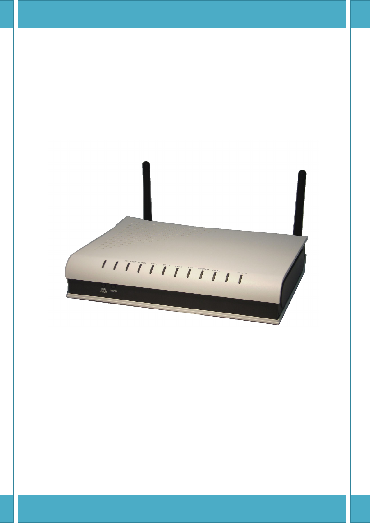
Proscend 130
ADSL2+/VDSL2 WLAN Router
User Manual
Version 0.02
Page 2

Contents
1 INTRODUCTION ........................................................................................................................................ 5
1.1 F
1.2 A
2 INSTALLATION .......................................................................................................................................... 7
2.1 H
2.2 LED I
3 WEB USER INTERFACE ............................................................................................................................ 11
3.1 D
EATURES
................................................................................................................................................... 5
1.1.1 Wireless LAN .................................................................................................................................... 5
1.1.2 Fast Wired Connections ................................................................................................................... 5
1.1.3 Quality Of Service ............................................................................................................................ 5
1.1.4 Safe & Secure Connections .............................................................................................................. 5
1.1.5 Remote Management ..................................................................................................................... 6
PPLICATION
ARDWARE SETUP
2.1.1 REAR PANEL ..................................................................................................................................... 7
2.1.2 FRONT PANEL .................................................................................................................................. 8
EFAULT SETTINGS
............................................................................................................................................... 6
....................................................................................................................................... 7
NDICATORS
.......................................................................................................................................... 9
..................................................................................................................................... 11
3.2 IP C
3.2.1 DHCP MODE .................................................................................................................................. 12
3.2.2 STATIC IP MODE ............................................................................................................................ 13
3.3 L
4 DEVICE INFORMATION ........................................................................................................................... 16
4.1 WAN ...................................................................................................................................................... 18
4.2 S
4.2.1 LAN Statistics ................................................................................................................................. 19
4.2.2 WAN Statistics ............................................................................................................................... 19
4.2.3 ATM Statistics ................................................................................................................................ 20
4.2.4 xDSL Statistics ................................................................................................................................ 22
4.3 R
4.4 ARP ........................................................................................................................................................ 29
4.5 DHCP ..................................................................................................................................................... 30
5 ADVANCED SETUP .................................................................................................................................. 31
ONFIGURATION
OGIN PROCEDURE
TATISTICS
OUTE
..................................................................................................................................................... 28
.................................................................................................................................... 12
..................................................................................................................................... 14
................................................................................................................................................ 19
5.1 L
5.2 WAN ...................................................................................................................................................... 34
5.3 LAN ........................................................................................................................................................ 36
AYER 2 INTERFACE
5.1.1 ATM Interface ................................................................................................................................ 32
5.1.2 PTM Interface ................................................................................................................................ 32
5.1.3 ETH WAN INTERFACE .................................................................................................................... 32
.................................................................................................................................... 32
Proscend 130 ADSL2+/VDSL2 WLAN Router User Manual V0.02 1
Page 3

5.4
IPV6 LAN H
OST
........................................................................................................................................ 39
5.5 NAT ........................................................................................................................................................ 40
5.5.1 Virtual Servers ............................................................................................................................... 40
5.5.2 Port Triggering .............................................................................................................................. 42
5.5.3 DMZ Host ....................................................................................................................................... 44
5.6 S
5.7 P
5.8 Q
5.9 R
ECURITY
.................................................................................................................................................. 45
5.6.1 IP Filtering ..................................................................................................................................... 45
5.6.2 MAC Filtering ................................................................................................................................. 48
ARENTAL CONTROL
5.7.1 Time Restriction ............................................................................................................................. 50
5.7.2 URL Filter ....................................................................................................................................... 51
UALITY OF SERVICE (QO
5.8.1 Queue Management Configuration .............................................................................................. 52
5.8.2 Queue Configuration ..................................................................................................................... 53
5.8.3 QoS Classification .......................................................................................................................... 55
OUTING
.................................................................................................................................................. 57
5.9.1 Default Gateway ........................................................................................................................... 57
5.9.2 Static Route ................................................................................................................................... 57
................................................................................................................................... 50
S) ......................................................................................................................... 52
5.9.3 Policy Routing ................................................................................................................................ 58
5.9.4 RIP ................................................................................................................................................. 59
5.9.5 IPv6 Static Route ........................................................................................................................... 59
5.10 DNS ........................................................................................................................................................ 60
5.10.1 DNS Server ..................................................................................................................................... 60
5.10.2 Dynamic DNS ................................................................................................................................. 60
5.11 DSL ......................................................................................................................................................... 62
5.12 UPNP ...................................................................................................................................................... 65
5.13 DNS P
5.14 I
5.15 C
5.15.1 Local .............................................................................................................................................. 70
5.15.2 Trusted CA ..................................................................................................................................... 72
5.16 P
6 WIRELESS ................................................................................................................................................ 74
6.1 B
ROXY
.............................................................................................................................................. 66
NTERFACE GROUPING
ERTIFICATE
OWER MANAGEMENT
ASIC
.............................................................................................................................................. 70
....................................................................................................................................................... 74
................................................................................................................................. 67
............................................................................................................................... 73
6.2 S
6.3 MAC F
6.4 W
6.5 A
6.6 S
ECURITY
.................................................................................................................................................. 76
6.2.1 WPS ............................................................................................................................................... 78
ILTER
............................................................................................................................................. 84
IRELESS BRIDGE
DVANCED
TATION INFO
...................................................................................................................................... 85
............................................................................................................................................... 86
........................................................................................................................................... 90
Proscend 130 ADSL2+/VDSL2 WLAN Router User Manual V0.02 2
Page 4

DIAGNOSTICS ......................................................................................................................................... 91
7
8 MANAGEMENT ....................................................................................................................................... 92
8.1 S
8.2 S
8.3 TR-069 C
8.4 I
8.5 A
8.6 U
8.7 R
9 APPENDIX ............................................................................................................................................. 102
9.1 F
9.2 SSH C
9.3 WSC E
ETTINGS
.................................................................................................................................................. 92
8.1.1 Backup Settings ............................................................................................................................. 92
8.1.2 Update Settings ............................................................................................................................. 92
8.1.3 Restore Default .............................................................................................................................. 93
YSTEM LOG
NTERNET TIME
CCESS CONTROL
8.5.1 Passwords ...................................................................................................................................... 99
PDATE SOFTWARE
EBOOT
IREWALL
............................................................................................................................................. 94
LIENT
......................................................................................................................................... 96
.......................................................................................................................................... 98
....................................................................................................................................... 99
.................................................................................................................................. 100
................................................................................................................................................. 101
............................................................................................................................................... 102
LIENT
............................................................................................................................................ 106
XTERNAL REGISTRAR
....................................................................................................................... 107
9.4 P
9.5 C
9.6 S
RINTER SERVER
ONNECTION SETUP
9.5.1 Layer 2 Interfaces ........................................................................................................................ 115
9.5.2 PTM Interfaces ............................................................................................................................ 116
9.5.3 ATM Interfaces ............................................................................................................................ 118
9.5.4 Ethernet WAN Interface .............................................................................................................. 120
9.5.5 WAN Connections ........................................................................................................................ 122
9.5.6 PPP over ETHERNET (PPPoE) ....................................................................................................... 123
9.5.7 IP over ETHERNET (IPoE) ............................................................................................................. 127
9.5.8 Bridging ....................................................................................................................................... 130
9.5.9 PPP over ATM (PPPoA) ................................................................................................................ 131
9.5.10 IP over ATM (IPoA) ...................................................................................................................... 135
9.5.11 More About MSC Mode ............................................................................................................... 138
PECIFICATIONS
9.6.1 Hardware..................................................................................................................................... 141
9.6.2 WAN Interface ............................................................................................................................. 141
9.6.3 LAN Interface ............................................................................................................................... 141
...................................................................................................................................... 109
................................................................................................................................. 115
....................................................................................................................................... 141
9.6.4 WLAN Interface ........................................................................................................................... 141
9.6.5 ATM Attributes ............................................................................................................................ 142
9.6.6 PTM Attributes ............................................................................................................................ 142
9.6.7 Management ............................................................................................................................... 142
9.6.8 Network Protocol ........................................................................................................................ 142
9.6.9 QoS .............................................................................................................................................. 142
Proscend 130 ADSL2+/VDSL2 WLAN Router User Manual V0.02 3
Page 5

9.6.10
Firewall/Filtering ......................................................................................................................... 143
9.6.11 NAT/NAPT ................................................................................................................................... 143
9.6.12 Security Functions........................................................................................................................ 143
9.6.13 Application Layer Gateway ......................................................................................................... 143
9.6.14 Power Supply ............................................................................................................................... 143
9.6.15 Environment Condition ................................................................................................................ 143
9.6.16 Dimensions .................................................................................................................................. 143
9.6.17 Kit Weight .................................................................................................................................... 143
Proscend 130 ADSL2+/VDSL2 WLAN Router User Manual V0.02 4
Page 6

1 Introduction
The Proscend 130 ADSL2+/VDSL2 WLAN Router provide wired and wireless access for high-bandwidth
applications in the home or office. It includes four RJ-45 Ethernet LAN ports and supports ADSL2+ and VDSL2
connections through one RJ-11 port. ADSL2+ connections support multiple simultaneously Internet connections
while VDSL2 connections are suitable for triple play (Video + Voice + Data) applications.
An integrated 802.11n (Version 2.0 draft) WLAN Access Point (AP) provides faster wireless connections with
increased range, when compared with 802.11b and 802.11g, without sacrificing backwards compatibility with
these older wireless standards. WPS (Wi-Fi Protected Setup) and Wi-Fi On/Off buttons are positioned on the
front panel for easy wireless network setup and control.
1.1 Features
1.1.1 Wireless LAN
An integrated 802.11n WLAN Access Point (AP) operates at speeds of up to 300 Mbps without sacrificing
backward compatibility with 802.11b/g.
The Wireless Protected Setup (WPS) feature makes wireless connection setup quick and secure, while you can
easily toggle the wireless function on or off with the WLAN switch on the front panel.
1.1.2 Fast Wired Connections
The Proscend 130 features ADSL2+ and VDSL2 (17a) with auto-switching based on DSLAM settings.
Four fast Ethernet ports support LAN traffic at speeds of up to 100 Mbps, and the integrated USB 2.0 Host port
supports printer server.
1.1.3 Quality Of Service
Classify, control, and prioritize diverse traffic types, for pristine video, toll-quality voice, and error-free data
transmissions.
1.1.4 Safe & Secure Connections
As the first level of protection, a Stateful Firewall (with DoS protection) and NAT/PAT help to isolate the LAN
from external threats. IP and MAC address filtering provide fine-grained access control to or from the network.
Advanced security technologies, such as Virtual Private Networks (VPN) with PPTP pass-through,
Proscend 130 ADSL2+/VDSL2 WLAN Router User Manual V0.02 5
Page 7
L2TP pass-through and IPSec pass-through ensure secure networking, and WPA/WPA2/802.1x/WEP guarantee
rock-solid security for wireless connections.
1.1.5 Remote Management
TR-069/TR-098/TR-111 standards compatibility ensures interoperability with central office remote
management equipment. From the user perspective this reduces downtime and frustration. For the service
provider it means improved customer relations and cost savings. Other management options include telnet, ssh
and a web user interface with advanced functionality.
1.2 Application
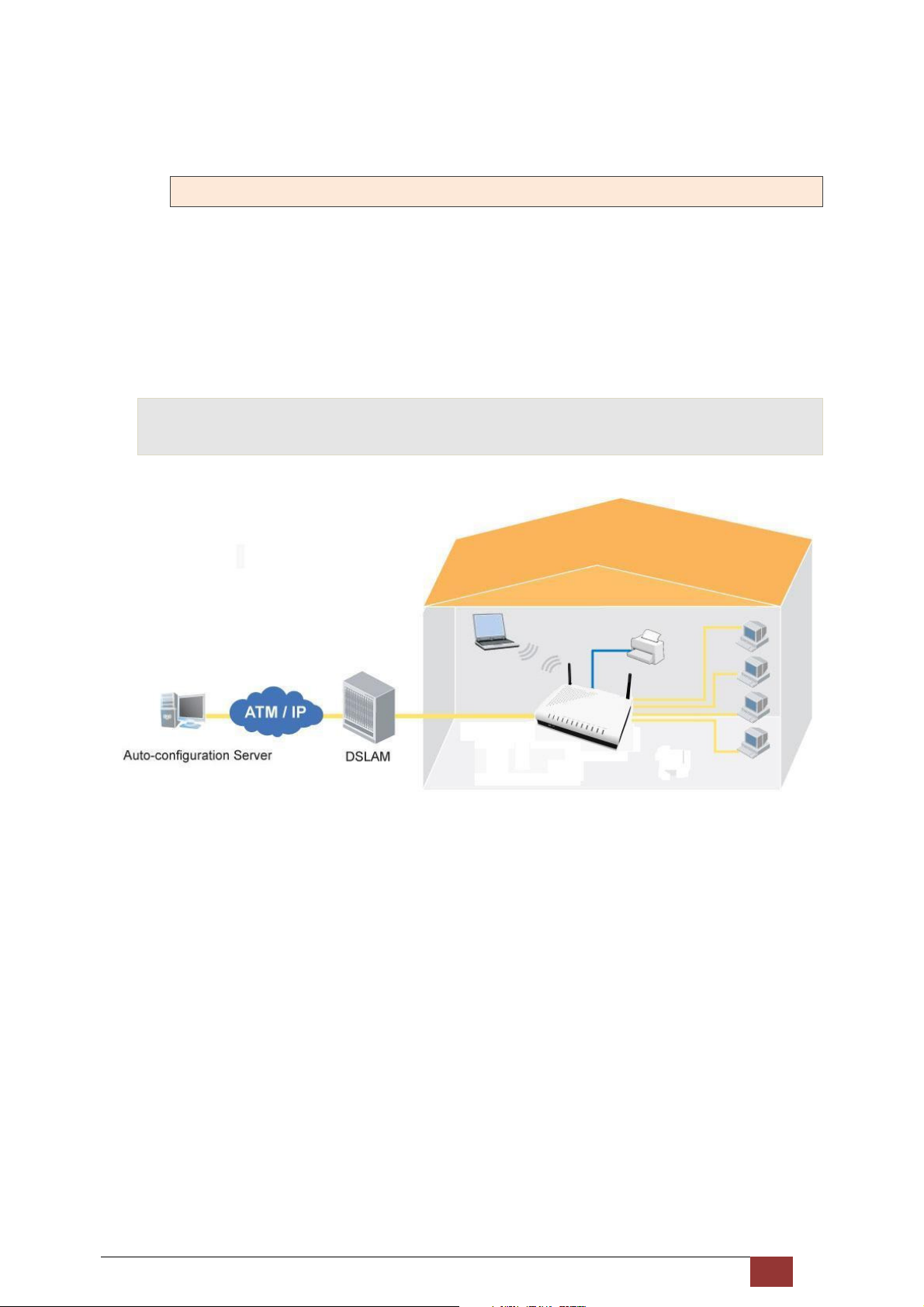
The following diagram depicts a typical application of the Proscend 130
Proscend 130 ADSL2+/VDSL2 WLAN Router User Manual V0.02 6
Page 8
2 Installation
2.1 Hardware Setup
Follow the instructions below to complete the hardware setup.
2.1.1 REAR PANEL
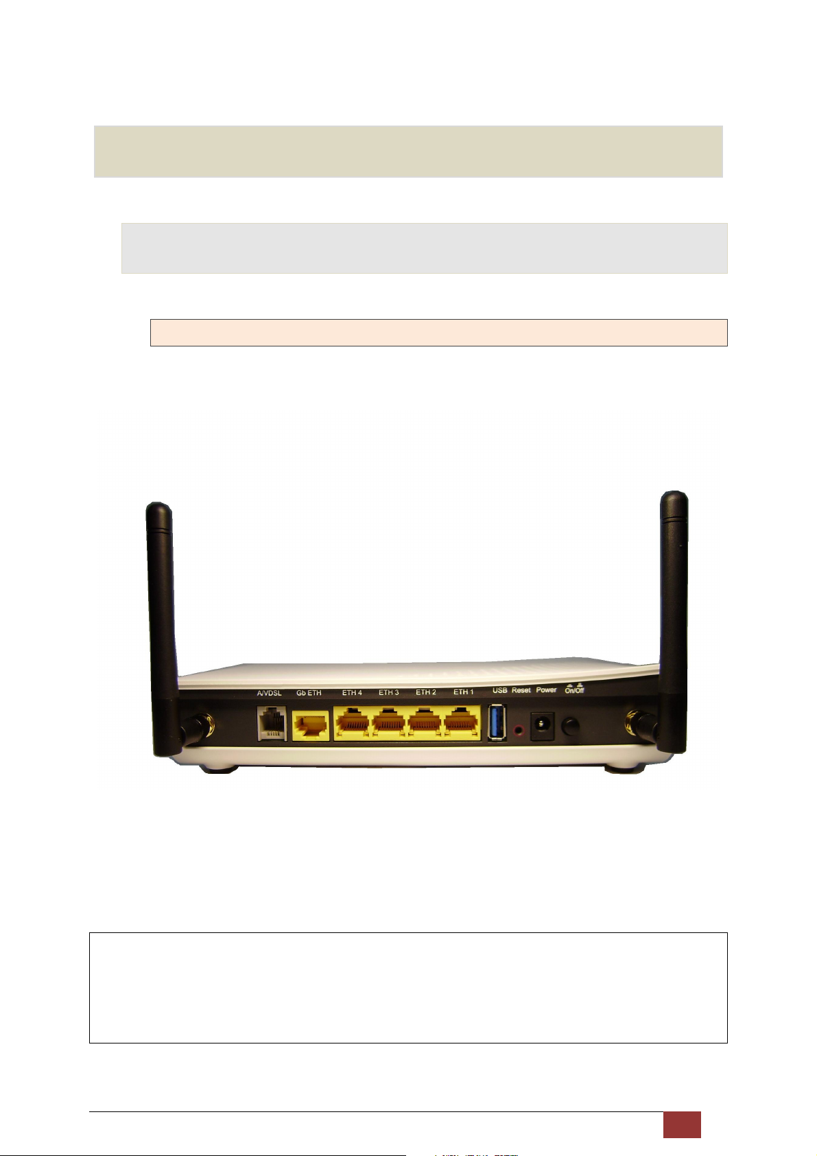
The figure below shows the back panel of the device.
On/Off Power Switch
Press the power button to the OFF position (OUT). Connect the power adapter to the power port. Attach the
power adapter to a wall outlet or other AC source. Press the power button to the ON position (IN). If the Power
LED displays as expected then the device is ready for setup.
Caution 1: If the device fails to power up, or it malfunctions, first verify that the power cords are connected
securely and then power it on again. If the problem persists, contact for technical support.
Caution 2: Before servicing or disassembling this equipment, disconnect all power cords and telephone lines
from their outlets.
Proscend 130 ADSL2+/VDSL2 WLAN Router User Manual V0.02 7
Page 9
Power
DC Power supply input socket.
Reset Button
Restore the default parameters of the device by pressing the Reset button for 5 to 10 seconds. After the device
has rebooted successfully, the front panel should display as expected.
NOTE: If pressed down for more than 20 seconds, the Proscend 130 will go into a firmware update state
(boot mode). The firmware can then be updated using an Internet browser pointed to the default
IP address.
USB Port
This is a USB 2.0 Host port, which can function as a Print Server
Ethernet (LAN1, LAN2, LAN3 and LAN4) Ports
Use 10/100 BASE-T RJ-45 cables to connect up to four network devices. These ports are auto-sensing MDI/MDX;
so either straight-through or crossover cable can be used.
Giga Ethernet (WAN) Ports
Use 10/100/1000 BASE-T RJ-45 cables to connect this network device. These ports are auto-sensing MDI/MDX;
so either straight-through or crossover cable can be used.
A/VDSL Port
Connect to an ADSL2+ or VDSL2 with this RJ11 Port.
2.1.2 FRONT PANEL
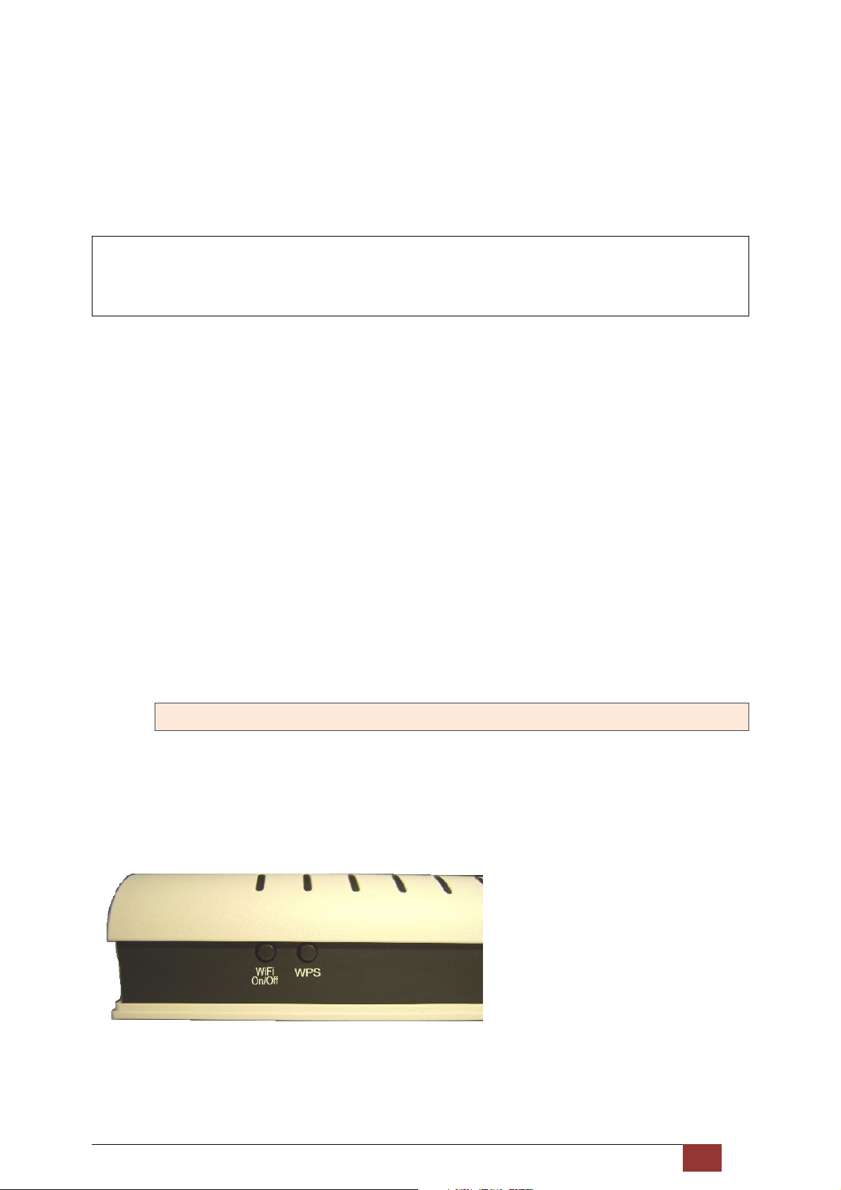
The Wi-Fi & WPS buttons are located on the bottom-left of the front panel, as shown.
Proscend 130 ADSL2+/VDSL2 WLAN Router User Manual V0.02 8
Page 10
WiFi On/Off Button
Press this button to enable/disable the wireless LAN (WLAN).
WPS Button
Press this button to begin searching for WPS clients. These clients must also enable
WPS push button mode. When WPS is available the WPS LED will be ON.
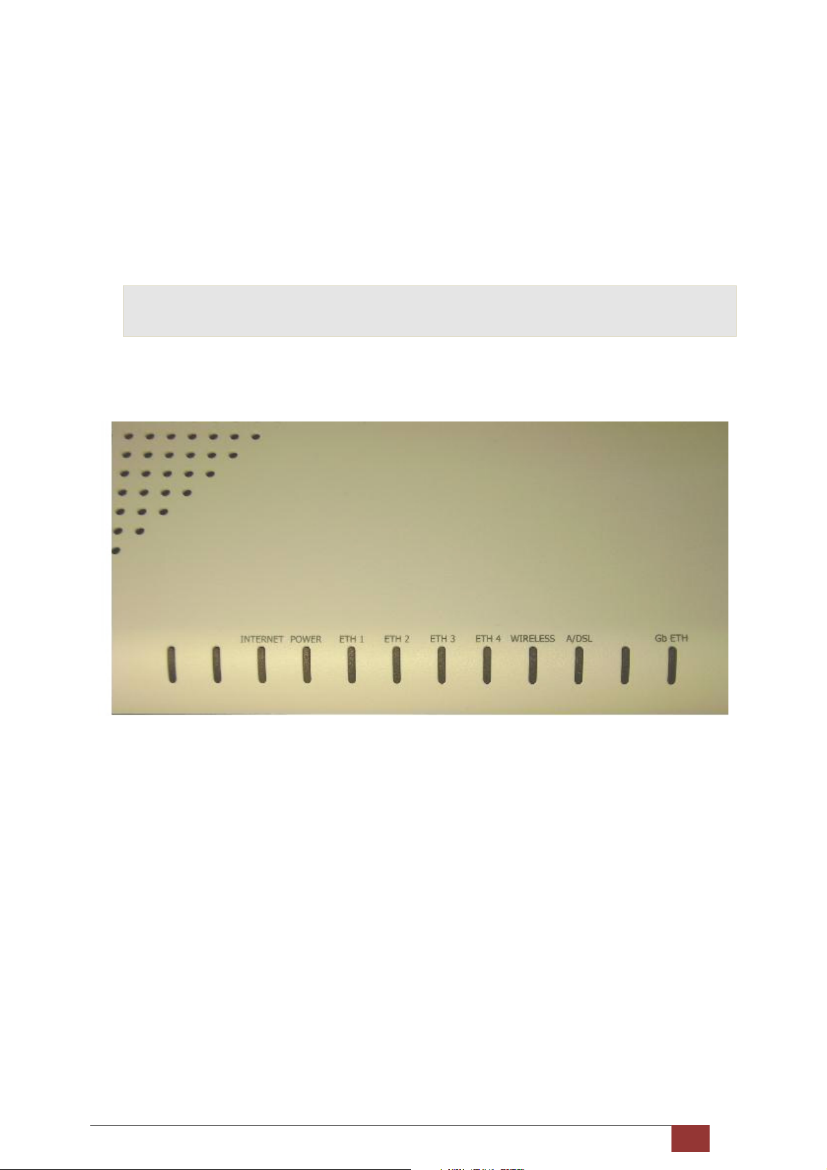
2.2 LED Indicators
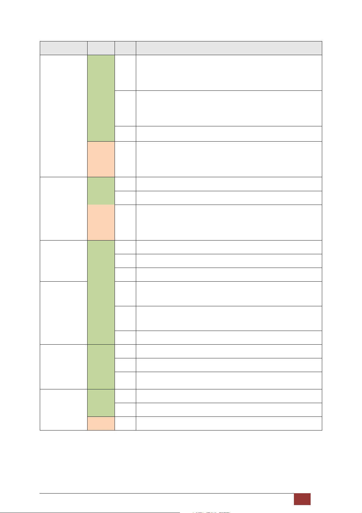
The front panel LED indicators are shown below and explained in the following table.
This information can be used to check the status of the device and its connections.
Proscend 130 ADSL2+/VDSL2 WLAN Router User Manual V0.02 9
Page 11
LED Color Mode
Green
INTERNET
Red On
Green
POWER
Red On
Function
IP connected and no traffic detected. If an IP or PPPoE session is
On
dropped due to an idle timeout, the light will remain green if an ADSL
connection is still present.
Modem power off, modem in bridged mode or ADSL connection not
Off
present. In addition, if an IP or PPPoE session is dropped for any
reason, other than an idle timeout, the light is turned off.
Blink IP connected and IP Traffic is passing thru the device (either direction)
Device attempted to become IP connected and failed (no DHCP
response, no PPPoE response, PPPoE authentication failed, no IP
address from IPCP, etc.)
On The device is powered up.
Off The device is powered down.
POST (Power On Self Test) failure or other malfunction. A malfunction
is any error of internal sequence or state that will prevent the device
ETH 1
ETH 2
ETH 3
Green
ETH 4
WIRELESS Green
A/VDSL Green
Green
Gb ETH
from connecting to the DSLAM or passing customer data.
On An Ethernet Link is established.
Off An Ethernet Link is not established.
Blink Data transmitting or receiving over LAN.
The wireless module is ready.
On
(i.e. installed and enabled).
The wireless module is not ready.
Off
(i.e. either not installed or disabled).
Blink Data transmitting or receiving over WLAN.
On ADSL2+/VDSL2 Link is established.
Off ADSL2+/VDSL2 Link is not established.
Blink ADSL2+/VDSL2 Link is training.
On An Ethernet Link is established.
Off An Ethernet Link is not established.
Red Blink Data transmitting or receiving over LAN.
Proscend 130 ADSL2+/VDSL2 WLAN Router User Manual V0.02 10
Page 12
3 Web User Interface
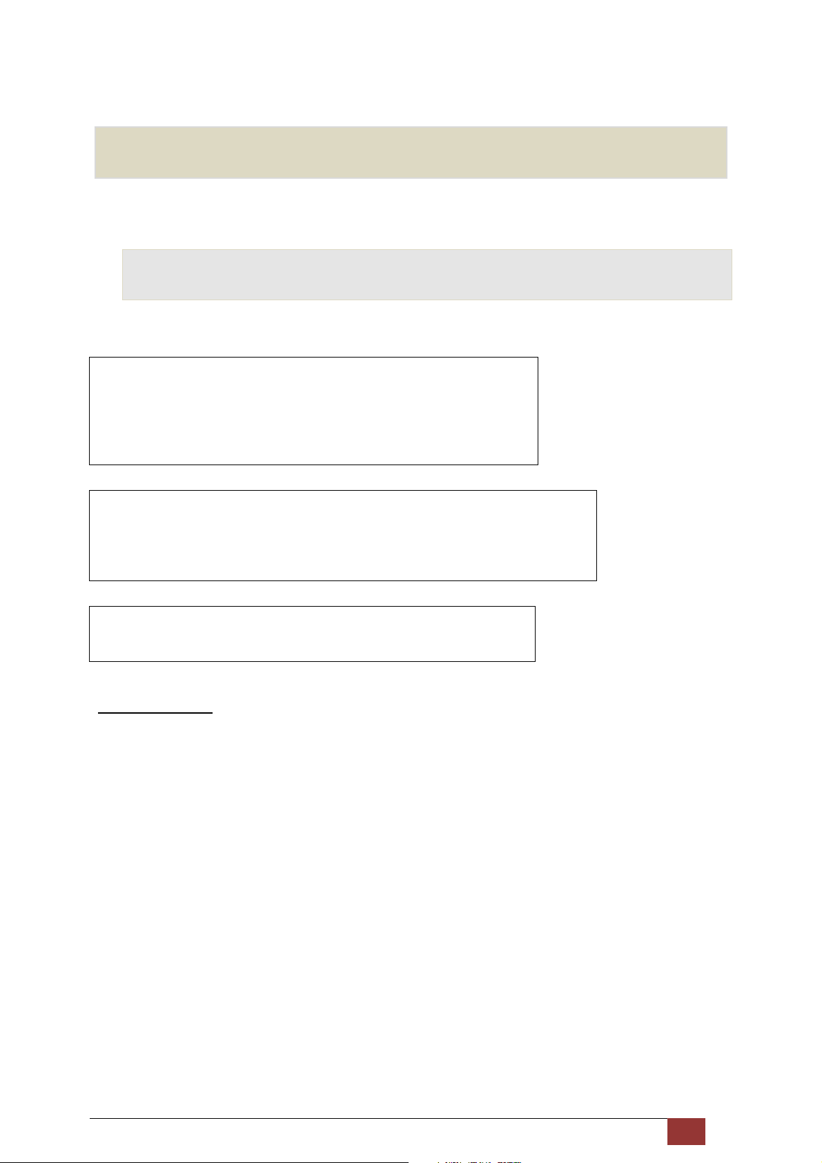
This section describes how to access the device via the web user interface (WUI) using an Internet browser
such as Internet Explorer (version 5.0 and later).
3.1 Default Settings
The factory default settings of this device are summarized below.
• LAN IP address: 192.168.1.1
• LAN subnet mask: 255.255.255.0
• Administrative access (username: root , password: 12345)
• User access (username: user, password: user)
• WAN IP address: none
• Remote WAN access: disabled
• Remote (WAN) access (username: support, password: support)
• WLAN access: enabled
• Service Set Identifier (SSID): WLAN
Technical Note
During power on, the device initializes all settings to default values. It will then read the configuration profile
from the permanent storage section of flash memory. The default attributes are overwritten when identical
attributes with different values are configured. The configuration profile in permanent storage can be created
via the web user interface or telnet user interface, or other management protocols.
The factory default configuration can be restored either by pushing the reset button for more than five seconds
until the power indicates LED blinking or by clicking the Restore Default Configuration option in the Restore
Settings screen.
Proscend 130 ADSL2+/VDSL2 WLAN Router User Manual V0.02 11
Page 13
3.2 IP Configuration
3.2.1 DHCP MODE
When the Proscend 130 powers up, the onboard DHCP server will switch on. Basically, the DHCP server issues
and reserves IP addresses for LAN devices, such as your PC.
To obtain an IP address from the DCHP server, follow the steps provided below.
NOTE: The following procedure assumes you are running Windows XP. However, the general steps
involved are similar for most operating systems (OS). Check your OS support documentation for
further details.
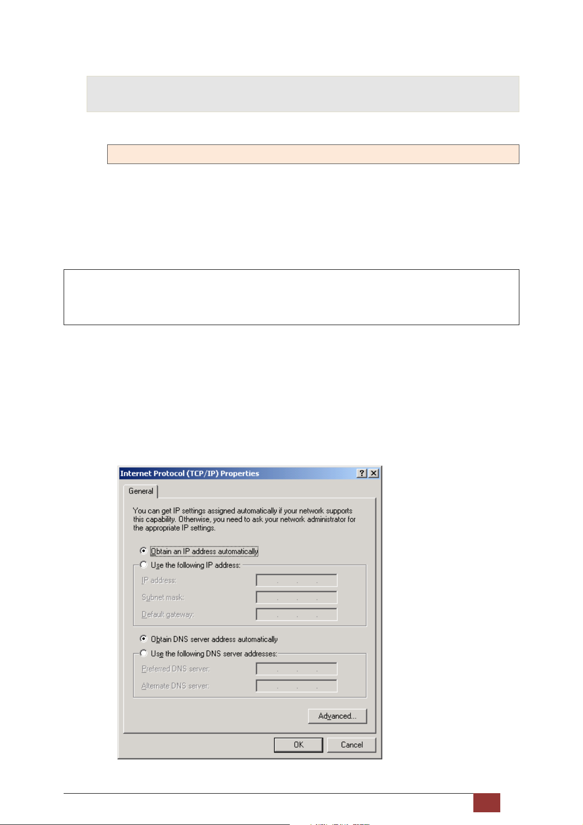
STEP 1: From the Network Connections window, open Local Area Connection (You may also access this
screen by double-clicking the Local Area Connection icon on your taskbar). Click the Properties
button.
STEP 2: Select Internet Protocol (TCP/IP) and click the Properties button.
STEP 3: Select Obtain an IP address automatically as shown below.
Proscend 130 ADSL2+/VDSL2 WLAN Router User Manual V0.02 12
Page 14
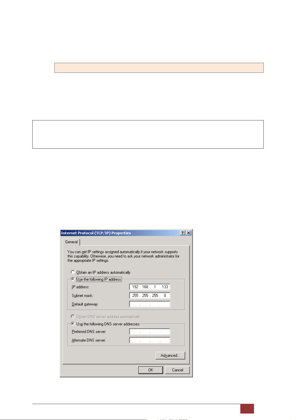
STEP 4: Click OK to submit these settings.
If you experience difficulty with DHCP mode, you can try static IP mode instead.
3.2.2 STATIC IP MODE
In static IP mode, you assign IP settings to your PC manually.
Follow these steps to configure your PC IP address to use subnet 192.168.1.x.
NOTE: The following procedure assumes you are running Windows XP. However, the general steps
involved are similar for most operating systems (OS). Check your OS support documentation for
further details.
STEP 1: From the Network Connections window, open Local Area Connection (You may also access this
screen by double-clicking the Local Area Connection icon on your taskbar). Click the Properties
button.
STEP 2: Select Internet Protocol (TCP/IP) and click the Properties button.
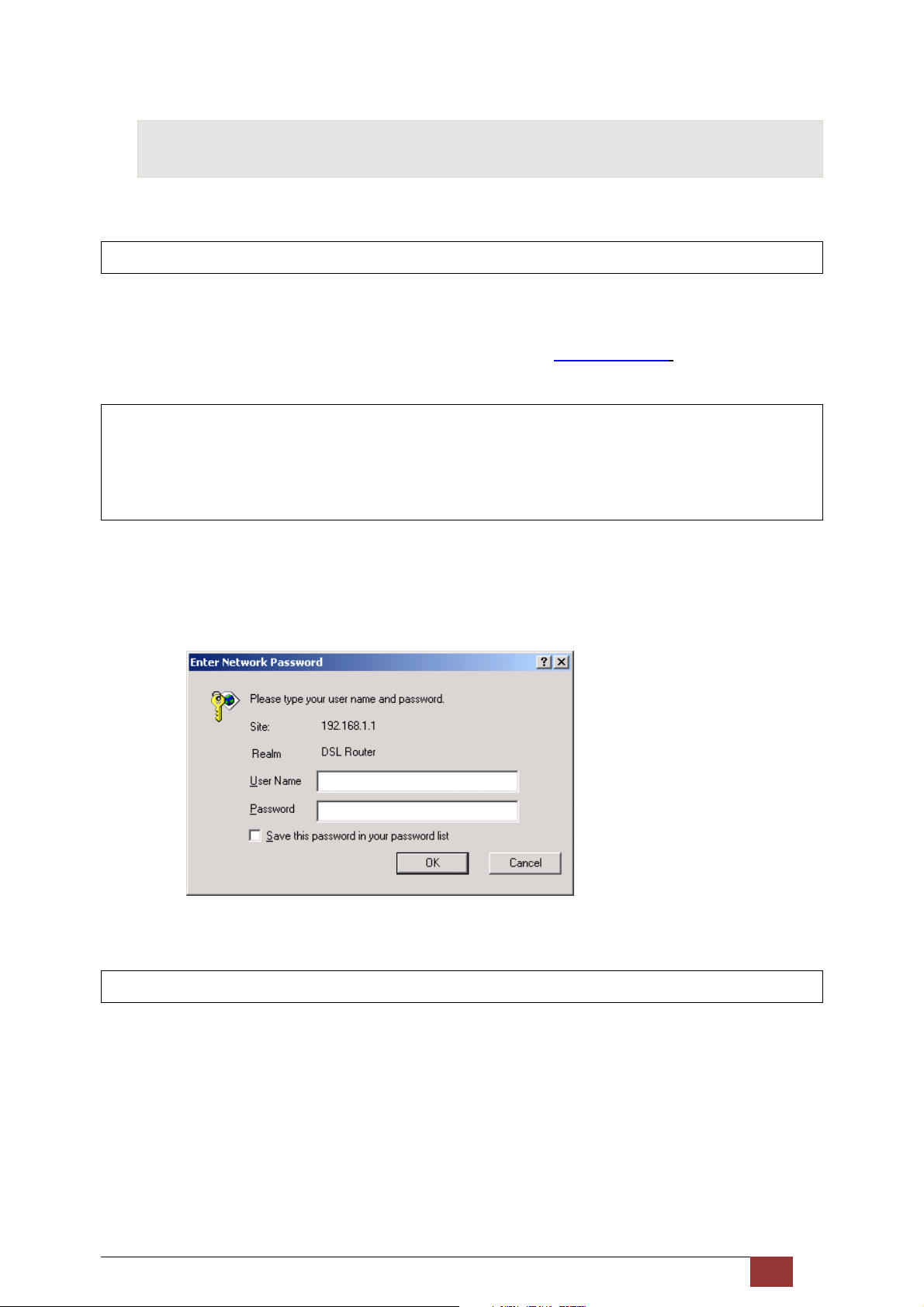
STEP 3: Change the IP address to the 192.168.1.x (1<x<255) subnet with subnet mask of 255.255.255.0.
The screen should now display as shown below.
STEP 4: Click OK to submit these settings.
Proscend 130 ADSL2+/VDSL2 WLAN Router User Manual V0.02 13
Page 15
3.3 Login Procedure
Perform the following steps to login to the web user interface.
NOTE: The default settings can be found in section 3.1.
STEP 1: Start the Internet browser and enter the default IP address for the device in the Web address field.
For example, if the default IP address is 192.168.1.1, type http://192.168.1.1.
NOTE: For local administration (i.e. LAN access), the PC running the browser must be attached to the
Ethernet, and not necessarily to the device.
For remote access (i.e. WAN), use the IP address shown on the Device Information screen and login
with remote username and password.
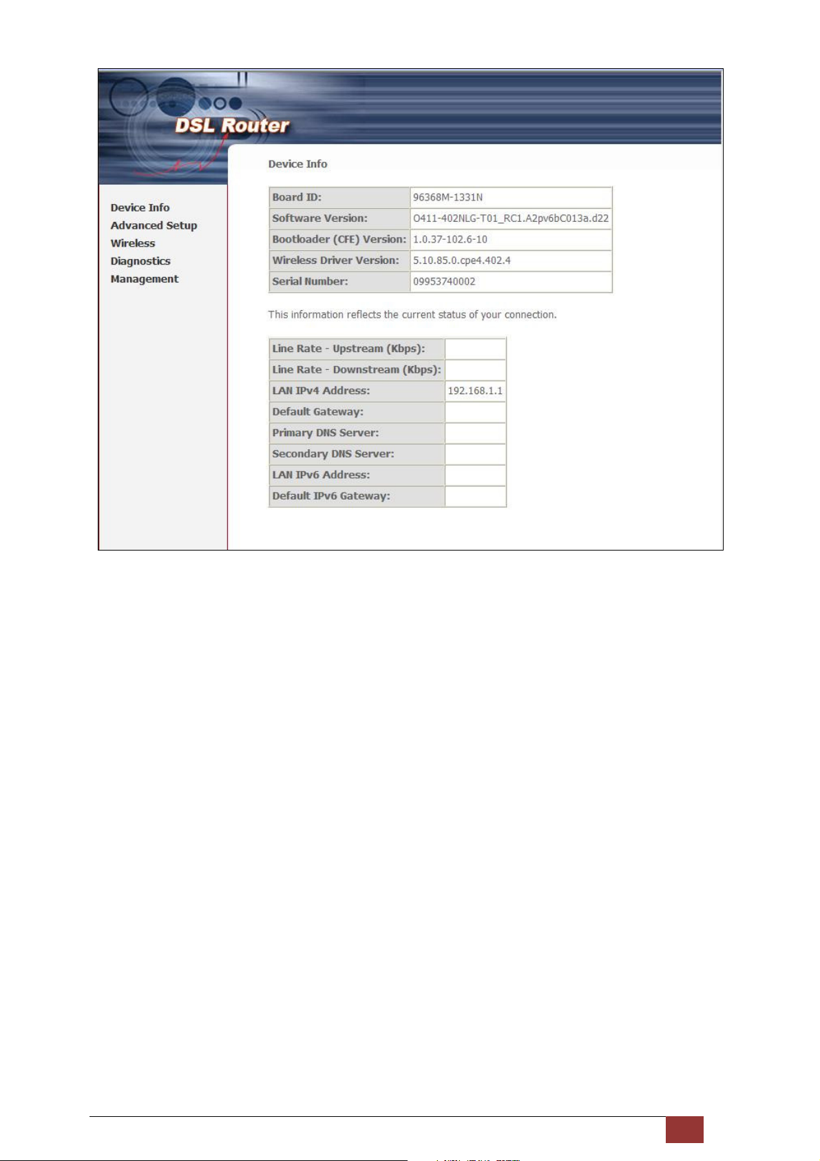
STEP 2: A dialog box will appear, such as the one below. Enter the default username and password, as
defined in section 3.1 Default Settings.
Click OK to continue.
NOTE: The login password can be changed later.
STEP 3: After successfully logging in for the first time, you will reach the start screen.
Proscend 130 ADSL2+/VDSL2 WLAN Router User Manual V0.02 14
Page 16
Proscend 130 ADSL2+/VDSL2 WLAN Router User Manual V0.02 15
Page 17
4 Device Information
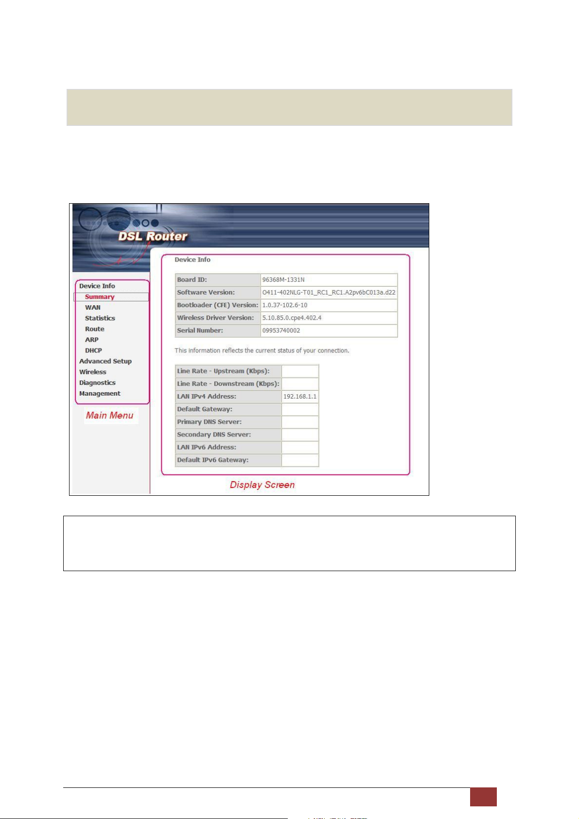
The web user interface window is divided into two frames, the main menu (at left) and the display screen (on
the right). The main menu has several options and selecting each of these options opens a submenu with more
selections.
NOTE: The menu items shown are based upon the configured connection(s) and user account privileges.
For example, if NAT and Firewall are enabled, the main menu will display the NAT and Security
submenus. If either is disabled, their corresponding menu(s) will also be disabled.
Device Info is the first selection on the main menu so it will be discussed first. Subsequent chapters will
introduce the other main menu options in sequence.
The Device Info Summary screen displays at startup.
Proscend 130 ADSL2+/VDSL2 WLAN Router User Manual V0.02 16
Page 18
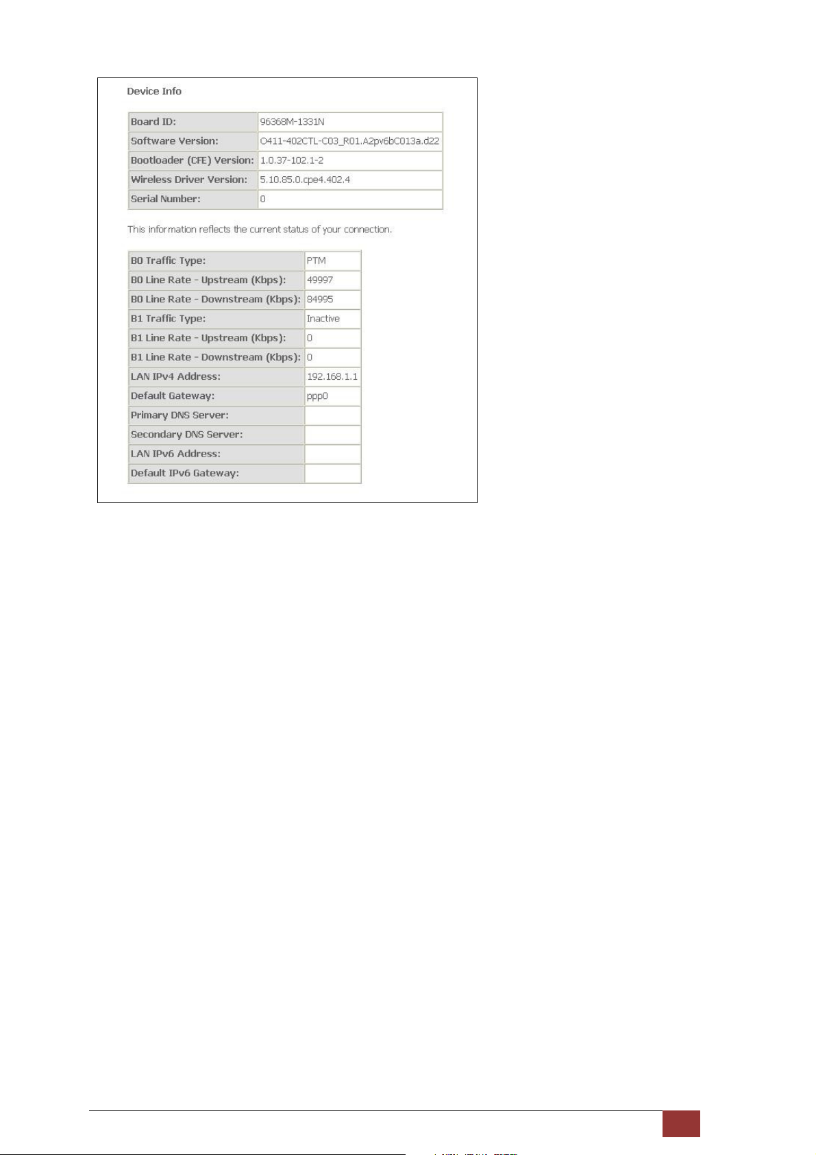
This screen shows hardware, software, IP settings and other related information.
Proscend 130 ADSL2+/VDSL2 WLAN Router User Manual V0.02 17
Page 19
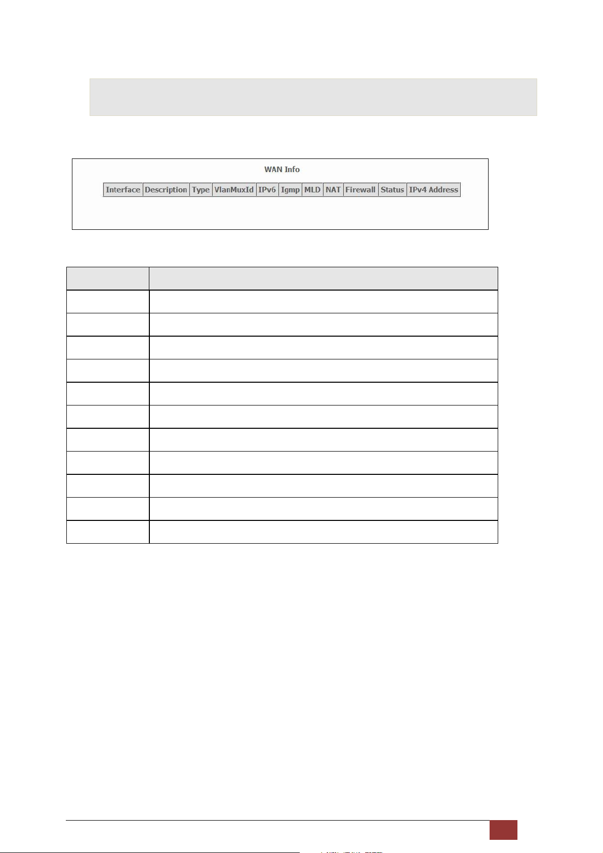
4.1 WAN
Select WAN from the Device Info submenu to display the configured PVC(s).
Heading Description
Interface Name of the interface for WAN
Description Name of the WAN connection
Type Shows the connection type
VlanMuxId Shows 802.1Q VLAN ID
IPv6 Shows WAN IPv6 address
IGMP Shows Internet Group Management Protocol (IGMP) status
MLD Shows Multicast Listener Discovery (MLD) status
NAT Shows Network Address Translation (NAT) status
Firewall Shows the status of Firewall
Status Lists the status of DSL link
IPv4 Address Shows WAN IPv4 address
Proscend 130 ADSL2+/VDSL2 WLAN Router User Manual V0.02 18
Page 20
4.2 Statistics
This selection provides LAN, WAN, ATM/PTM and xDSL statistics.
NOTE: These screens are updated automatically every 15 seconds.
Click Reset Statistics to perform a manual update.
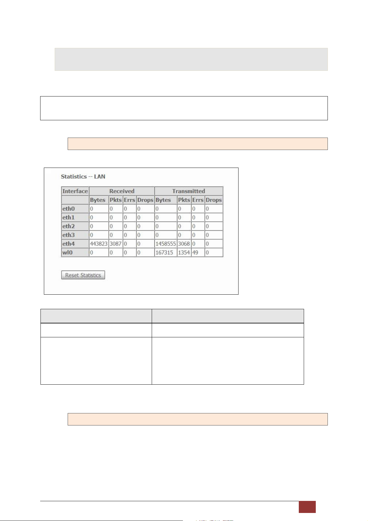
4.2.1 LAN Statistics
This screen shows data traffic statistics for each LAN interface.
Heading Description
Interface LAN interface(s)
Received/Transmitted: - Bytes
- Pkts
- Errs
- Drops
Number of Bytes
Number of Packets
Number of packets with errors
Number of dropped packets
4.2.2 WAN Statistics
This screen shows data traffic statistics for each WAN interface.
Proscend 130 ADSL2+/VDSL2 WLAN Router User Manual V0.02 19
Page 21
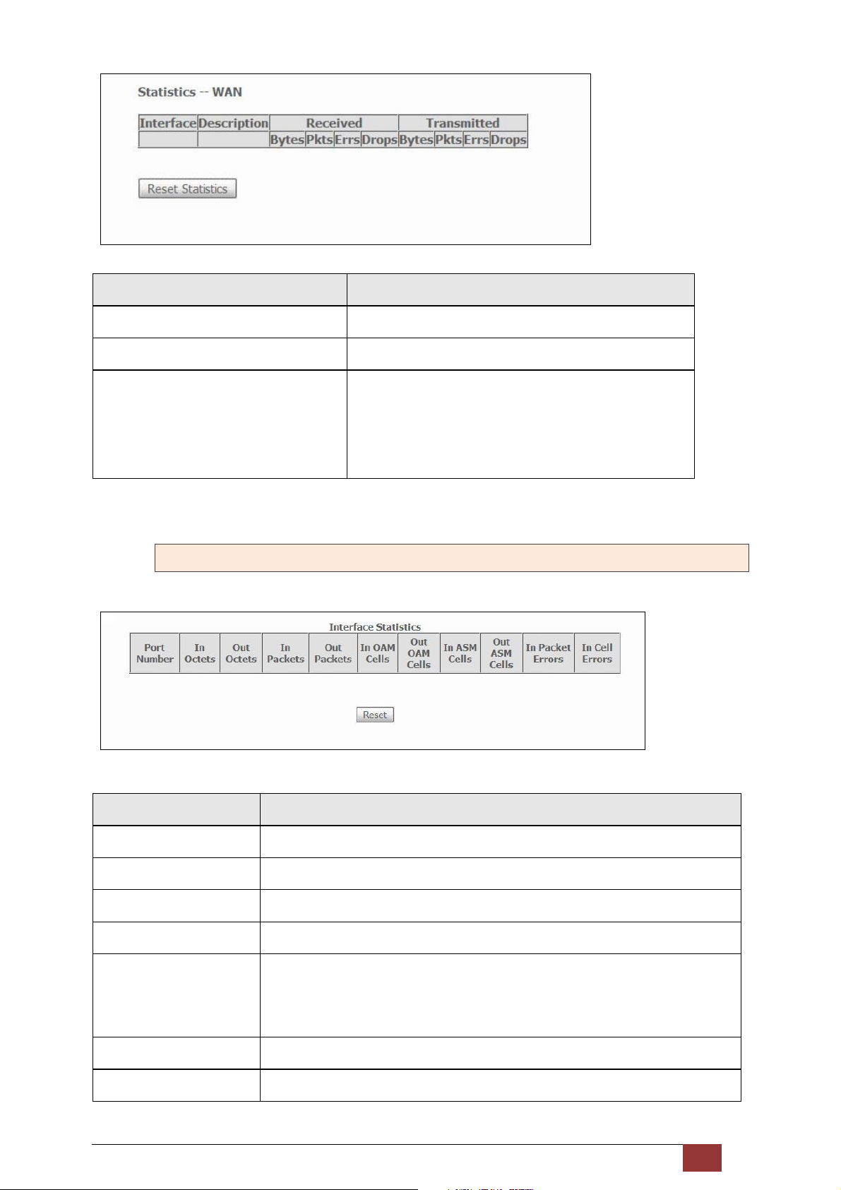
Heading Description
Interface WAN interfaces
Description WAN service label
Received/Transmitted - Bytes
- Pkts
- Errs
- Drops
Number of Bytes
Number of Packets
Number of packets with errors
Number of dropped packets
4.2.3 ATM Statistics
The following figure shows Asynchronous Transfer Mode (ATM) statistics.
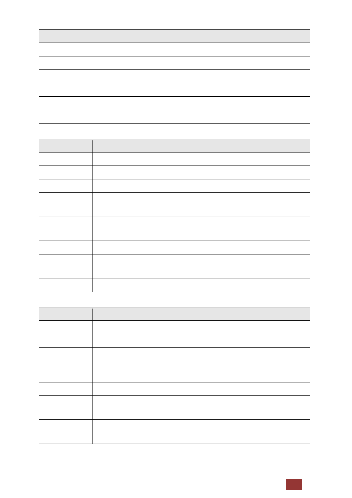
ATM Interface Statistics
Heading Description
Port Number ATM PORT (0-3)
In Octets Number of received octets over the interface
Out Octets Number of transmitted octets over the interface
In Errors Number of cells dropped due to uncorrectable HEC errors
In Unknown Number of received cells discarded during cell header validation, including cells
with unrecognized VPI/VCI values, and cells with invalid cell header patterns. If
cells with undefined PTI values are discarded, they are also counted here.
In Hec Errors Number of cells received with an ATM Cell Header HEC error
In Invalid Vpi Vci Errors Number of cells received with an unregistered VCC address.
Proscend 130 ADSL2+/VDSL2 WLAN Router User Manual V0.02 20
Page 22
Heading Description
In Port Not Enable Errors Number of cells received on a port that has not been enabled.
In PTI Errors Number of cells received with an ATM header Payload Type Indicator (PTI) error
In Idle Cells Number of idle cells received
In Circuit Type Errors Number of cells received with an illegal circuit type
In OAM RM CRC Errors Number of OAM and RM cells received with CRC errors
In GFC Errors Number of cells received with a non-zero GFC.
AAL5 Interface Statistics
Heading Description
In Octets Number of received AAL5/AAL0 CPCS PDU octets
Out Octets Number of received AAL5/AAL0 CPCS PDU octets transmitted
In Ucast Pkts Number of received AAL5/AAL0 CPCS PDUs passed to a higher-layer for transmission
Out Ucast Pkts Number of received AAL5/AAL0 CPCS PDUs received from a higher layer for
transmission
In Errors Number of received AAL5/AAL0 CPCS PDUs received that contain an error. These
errors include CRC-32 errors.
Out Errors Number of received AAL5/AAL0 CPCS PDUs that could not be transmitted due to errors.
In Discards Number of received AAL5/AAL0 CPCS PDUs discarded due to an input buffer overflow
condition.
Out Discards This field is not currently used
AAL5 VCC Statistics
Heading Description
VPI/VCI ATM Virtual Path/Channel Identifiers
CRC Errors Number of PDUs received with CRC-32 errors
SAR Timeouts Number of partially re-assembled PDUs that were discarded because they were not
fully re-assembled within the required period of time. If the re-assembly time is not
supported, then this object contains a zero value.
Oversized SDUs Number of PDUs discarded because the corresponding SDU was too large
Short Packet Errors Number of PDUs discarded because the PDU length was less than the size of the AAL5
trailer
Length Errors Number of PDUs discarded because the PDU length did not match the length in the
AAL5 trailer
Proscend 130 ADSL2+/VDSL2 WLAN Router User Manual V0.02 21
Page 23
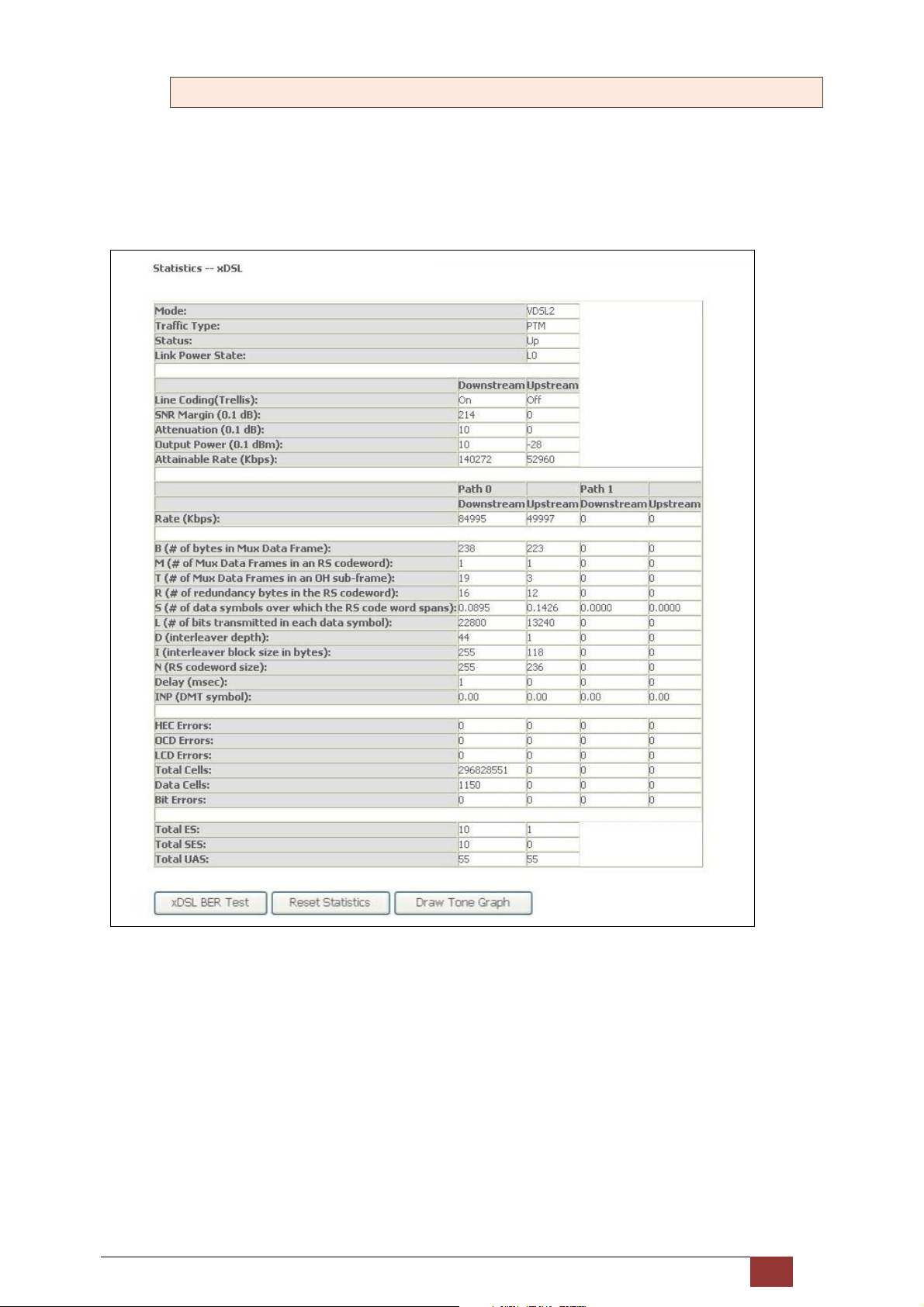
4.2.4 xDSL Statistics
The xDSL Statistics screen displays information corresponding to the xDSL type. The two examples below
(VDSL2 & ADSL2+) show this variation.
VDSL2
Proscend 130 ADSL2+/VDSL2 WLAN Router User Manual V0.02 22
Page 24
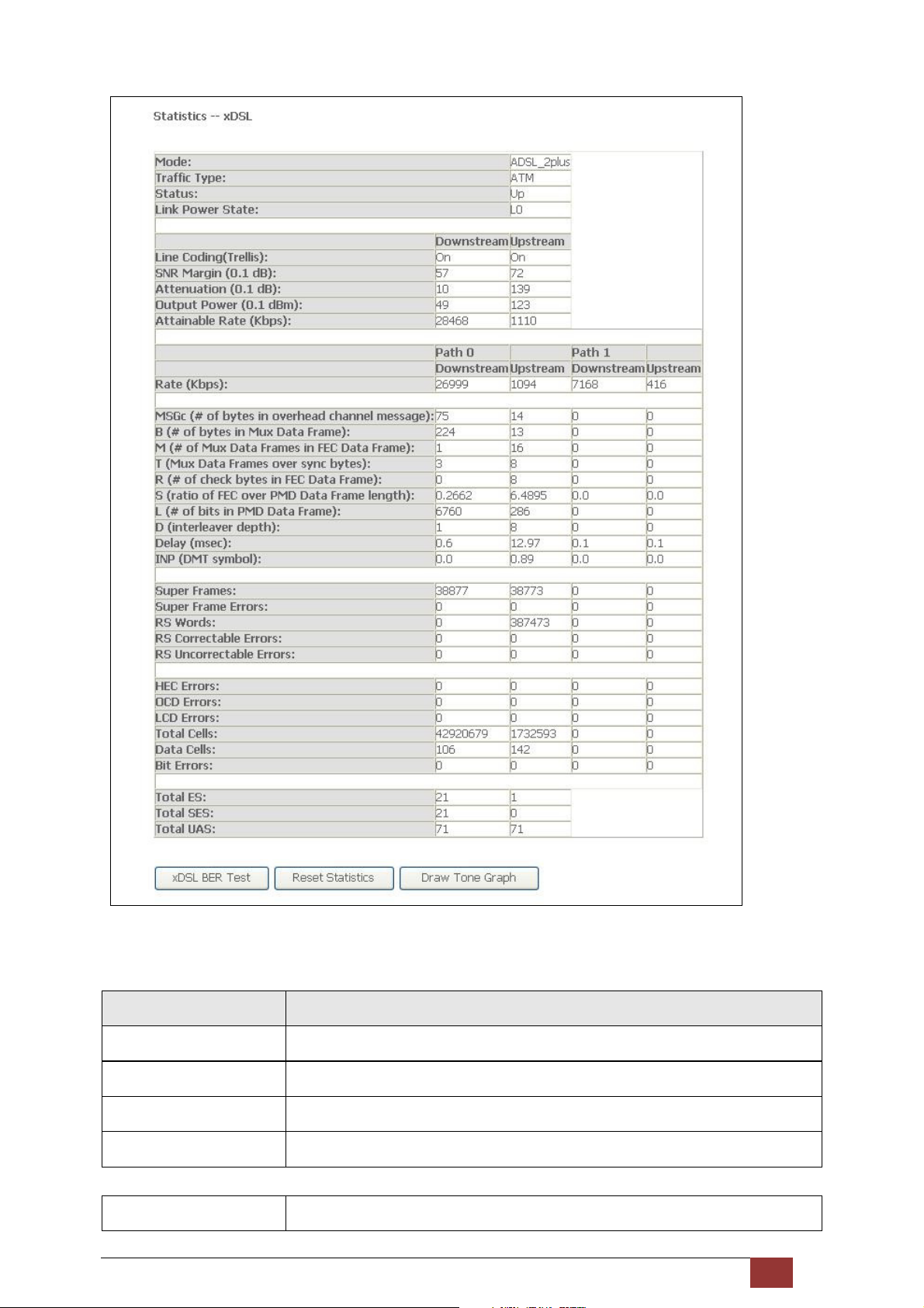
ADSL2+
Click the Reset Statistics button to refresh this screen.
Field Description
Mode G.Dmt, G.lite, T1.413, ADSL2, ADSL2+
Traffic Type Channel type Interleave or Fast
Status Lists the status of the DSL link
Link Power State Link output power state.
Line Coding (Trellis) Trellis On/Off
Proscend 130 ADSL2+/VDSL2 WLAN Router User Manual V0.02 23
Page 25

SNR Margin (0.1 dB) Signal to Noise Ratio (SNR) margin
Attenuation (0.1 dB) Estimate of average loop attenuation in the downstream direction.
Output Power (0.1 dBm) Total upstream output power
Attainable Rate (Kbps) The sync rate you would obtain.
Rate (Kbps) Current sync rates downstream/upstream
In VDSL2 mode, the following section is inserted.
B Number of bytes in Mux Data Frame
M Number of Mux Data Frames in a RS codeword
T Number of Mux Data Frames in an OH sub-frame
R Number of redundancy bytes in the RS codeword
S Number of data symbols the RS codeword spans
L Number of bits transmitted in each data symbol
D The interleaver depth
I The interleaver block size in bytes
N RS codeword size
Delay The delay in milliseconds (msec)
INP DMT symbol
In ADSL2+ mode, the following section is inserted.
MSGc Number of bytes in overhead channel message
B Number of bytes in Mux Data Frame
M Number of Mux Data Frames in FEC Data Frame
T Mux Data Frames over sync bytes
R Number of check bytes in FEC Data Frame
S Ratio of FEC over PMD Data Frame length
L Number of bits in PMD Data Frame
D The interleaver depth
Delay The delay in milliseconds (msec)
INP DMT symbol
In G.DMT mode, the following section is inserted.
Proscend 130 ADSL2+/VDSL2 WLAN Router User Manual V0.02 24
Page 26

K Number of bytes in DMT frame
R Number of check bytes in RS code word
S RS code word size in DMT frame
D The interleaver depth
Delay The delay in milliseconds (msec)
Super Frames Total number of super frames
Super Frame Errors Number of super frames received with errors
RS Words Total number of Reed-Solomon code errors
RS Correctable Errors Total Number of RS with correctable errors
RS Uncorrectable Errors Total Number of RS words with uncorrectable errors
HEC Errors Total Number of Header Error Checksum errors
OCD Errors Total Number of Out-of-Cell Delineation errors
LCD Errors Total number of Loss of Cell Delineation
Total Cells Total number of ATM cells (including idle + data cells)
Data Cells Total number of ATM data cells
Bit Errors Total number of bit errors
Total ES Total Number of Errored Seconds
Total SES Total Number of Severely Errored Seconds
Total UAS Total Number of Unavailable Seconds
Proscend 130 ADSL2+/VDSL2 WLAN Router User Manual V0.02 25
Page 27
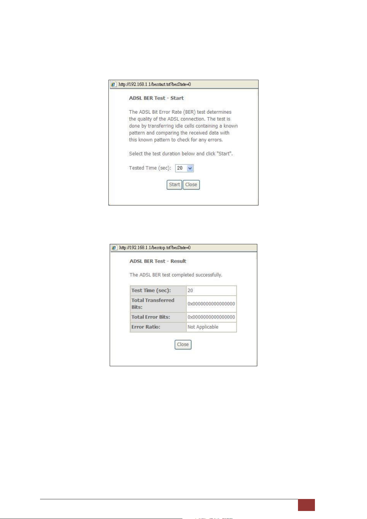
xDSL BER TEST
Click xDSL BER Test on the xDSL Statistics screen to test the Bit Error Rate (BER). A small pop-up window will
open after the button is pressed, as shown below.
Click Start to start the test or click Close to cancel the test. After the BER testing is complete, the pop-up
window will display as follows.
Proscend 130 ADSL2+/VDSL2 WLAN Router User Manual V0.02 26
Page 28
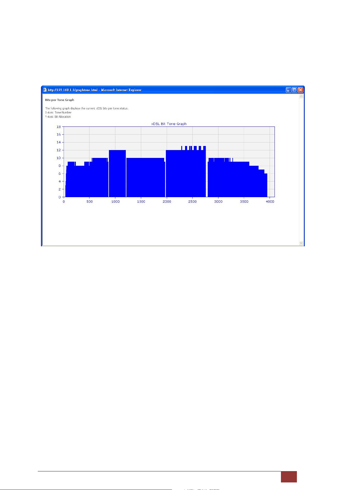
xDSL TONE GRAPH
Click Draw Tone Graph on the xDSL Statistics screen and a pop-up window will display the xDSL bits per tone
status, as shown below.
Proscend 130 ADSL2+/VDSL2 WLAN Router User Manual V0.02 27
Page 29
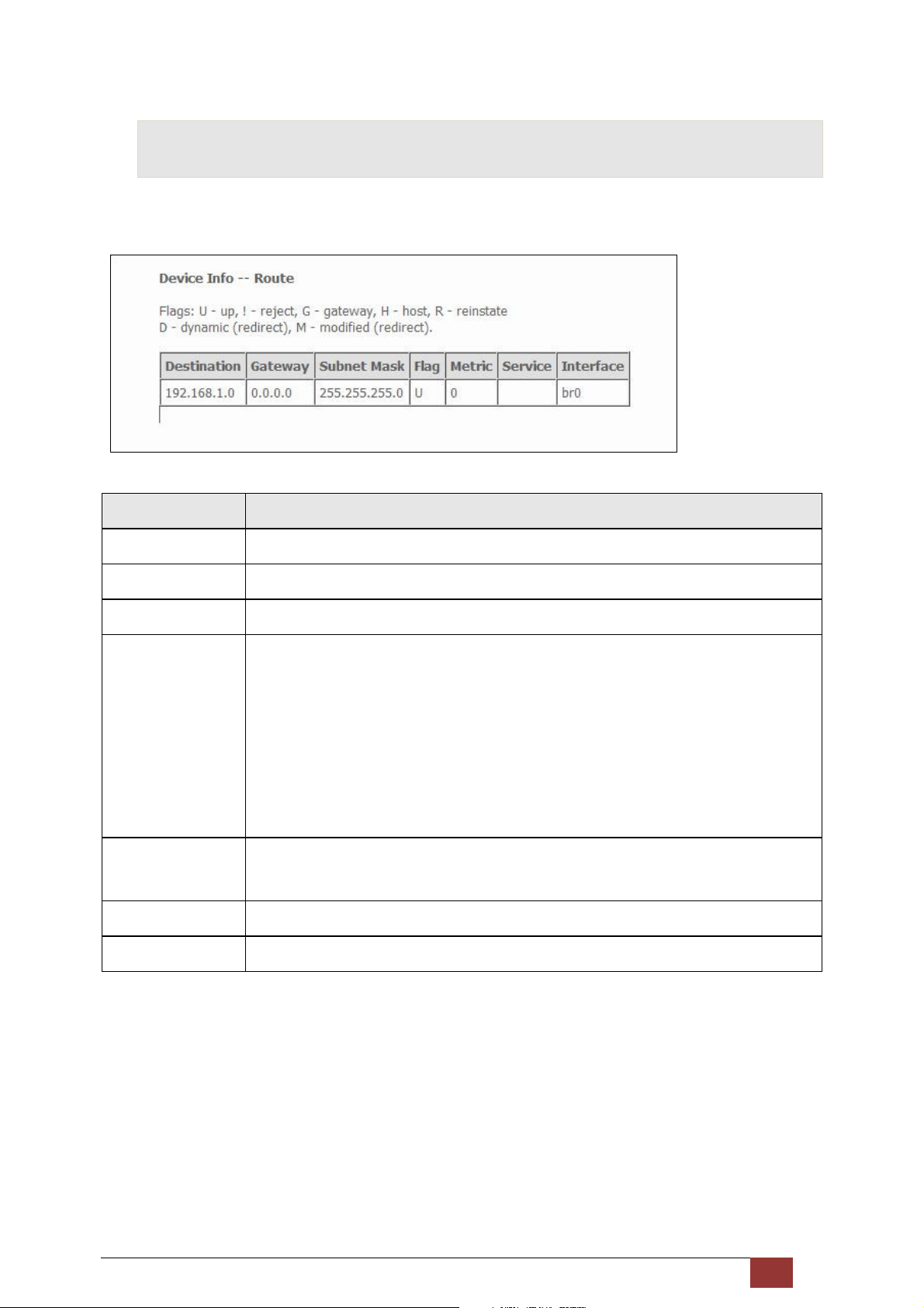
4.3 Route
Choose Route to display the routes that the Proscend 130 has found.
Field Description
Destination Destination network or destination host
Gateway Next hub IP address
Subnet Mask Subnet Mask of Destination
Flag U: route is up
! : reject route
G: use gateway
H: target is a host
R: reinstate route for dynamic routing
D: dynamically installed by daemon or redirect
M: modified from routing daemon or redirect
Metric The 'distance' to the target (usually counted in hops). It is not used by recent kernels,
but may be needed by routing daemons.
Service Shows the WAN connection label
Interface Shows connection interfaces
Proscend 130 ADSL2+/VDSL2 WLAN Router User Manual V0.02 28
Page 30
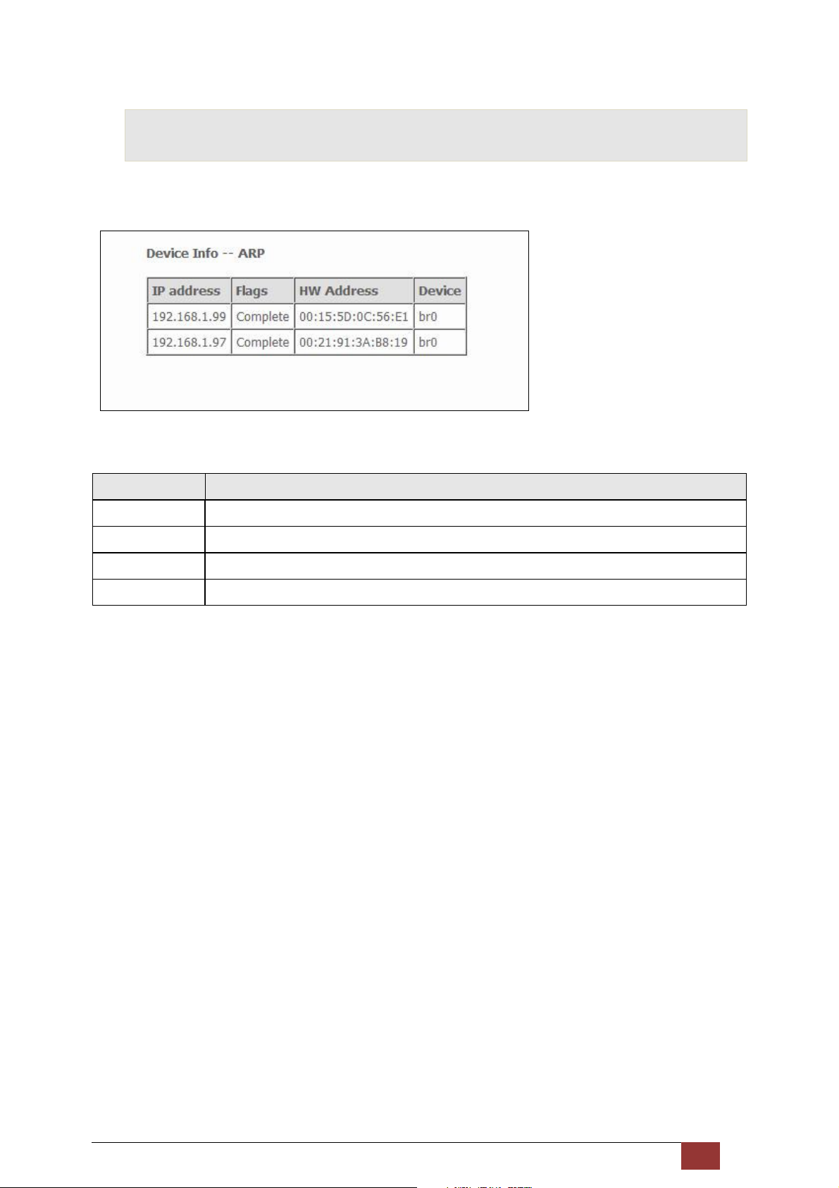
4.4 ARP
Click ARP to display the ARP information.
Field Description
IP address Shows IP address of host pc
Flags Complete, Incomplete, Permanent, or Publish
HW Address Shows the MAC address of host pc
Device Shows the connection interface
Proscend 130 ADSL2+/VDSL2 WLAN Router User Manual V0.02 29
Page 31
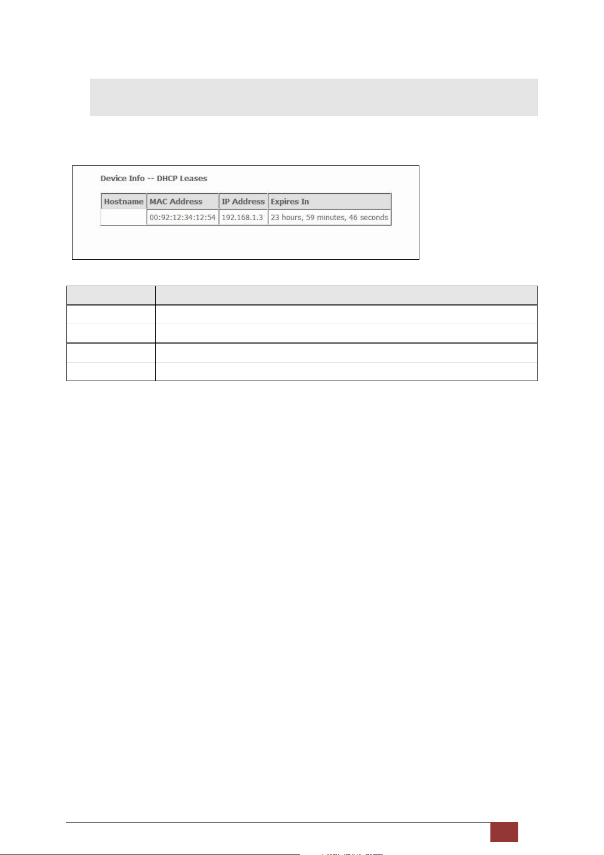
4.5 DHCP
Click DHCP to display all DHCP Leases.
Field Description
Hostname Shows the device/host/PC network name
MAC Address Shows the Ethernet MAC address of the device/host/PC
IP Address Shows IP address of device/host/PC
Expires In Shows how much time is left for each DHCP Lease
Proscend 130 ADSL2+/VDSL2 WLAN Router User Manual V0.02 30
Page 32

5 Advanced Setup
This chapter explains the following items:
5.1 Layer 2 Interface 5.2 WAN
5.3 LAN 5.4 IPv6 LAN Host
5.5 NAT 5.6 Security
5.7 Parental Control 5.8 Quality of Service (QoS)
5.9 Routing 5.10 DNS
5.11 DSL 5.12 UPnP
5.13 DNS Proxy 5.14 Interface Grouping
5.15 Certificate 5.16 Power Management
Proscend 130 ADSL2+/VDSL2 WLAN Router User Manual V0.02 31
Page 33
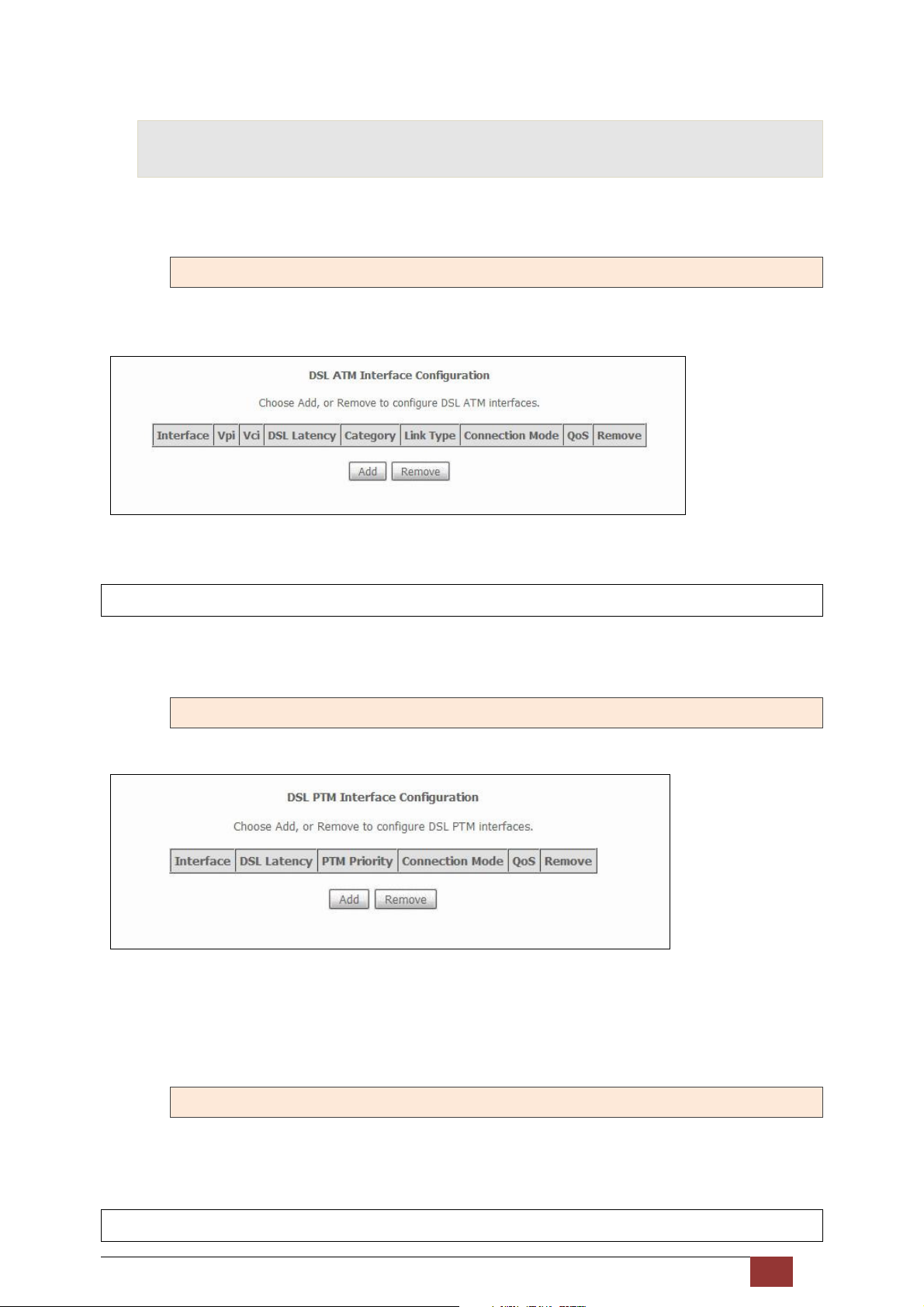
5.1 Layer 2 Interface
The ATM, PTM and ETH WAN interface screens are described here.
5.1.1 ATM Interface
Add or remove ATM interface connections here.
Click Add to create a new ATM interface.
NOTE: Up to 8 ATM interfaces can be created and saved in flash memory.
To remove a connection, select its Remove column radio button and click Remove.
5.1.2 PTM Interface
Add or remove PTM interface connections here.
Click Add to create a new connection . To remove a connection, select its Remove column radio button and
click Remove.
5.1.3 ETH WAN INTERFACE
This screen displays the Ethernet WAN Interface configuration.
NOTE: This option only applies to models with an Ethernet WAN port.
Proscend 130 ADSL2+/VDSL2 WLAN Router User Manual V0.02 32
Page 34
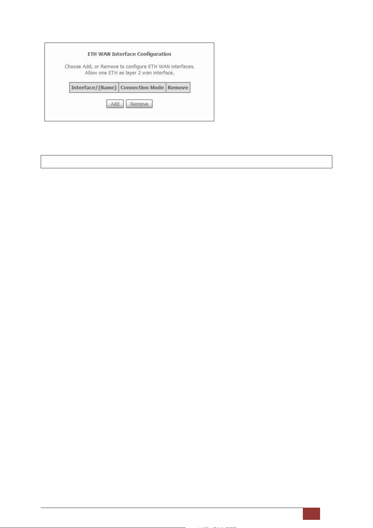
Click Add to create a new connection.
NOTE: One Ethernet WAN interface can be created and saved in flash memory.
To remove a connection, select its Remove column radio button and click remove.
Proscend 130 ADSL2+/VDSL2 WLAN Router User Manual V0.02 33
Page 35
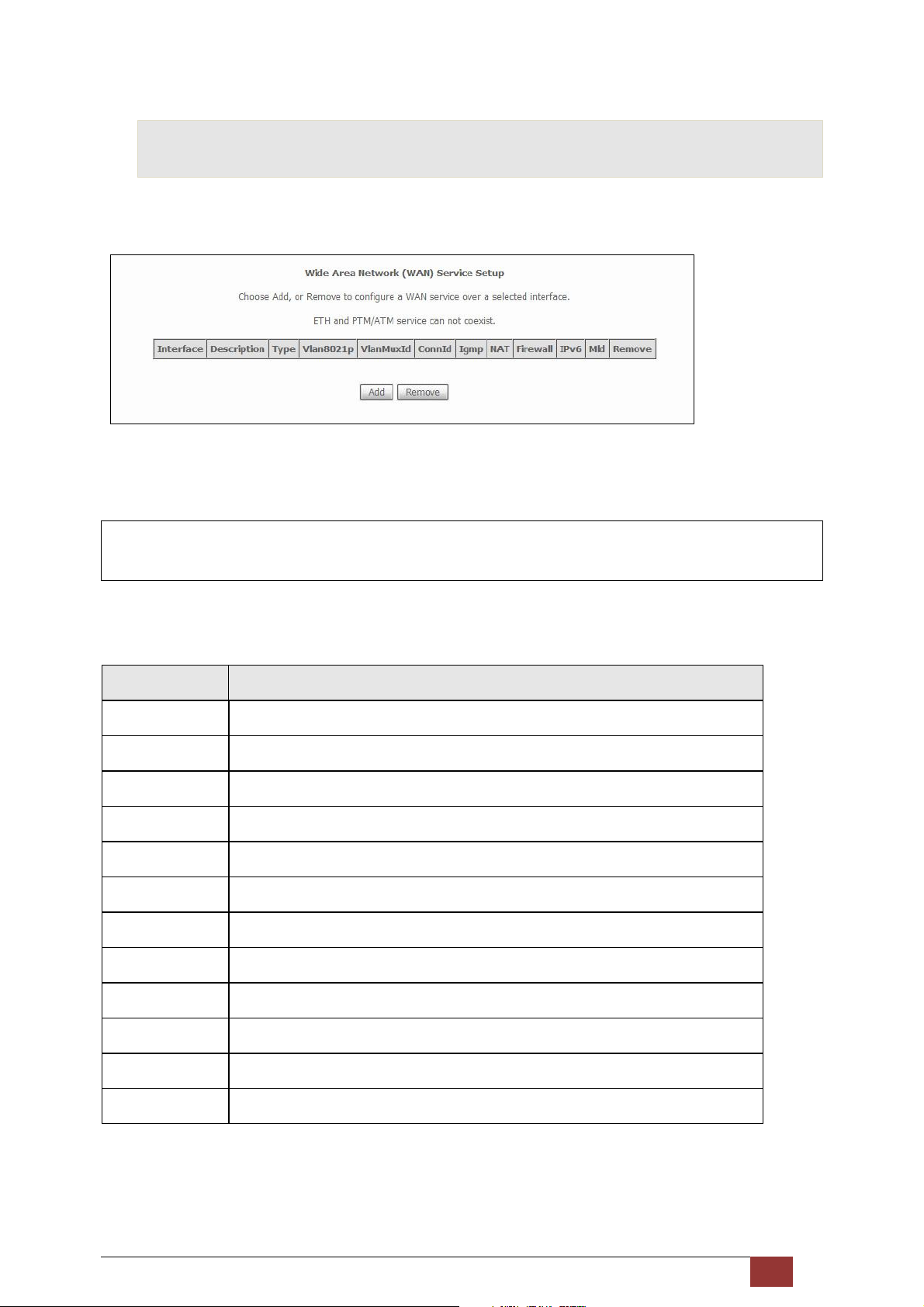
5.2 WAN
This screen allows for the configuration of WAN interfaces.
Click the Add button to create a new connection. For connections on ATM or ETH WAN interfaces see 9.5.
NOTE: ETH and ATM service connections cannot coexist. In Default Mode, up to 8 WAN connections can
be configured; while VLAN Mux and MSC Connection Modes support up to 16 WAN connections.
To remove a connection, select its Remove column radio button and click Remove.
Heading Description
Interface Name of the interface for WAN
Description Name of the WAN connection
Type Shows the connection type
Vlan8021p VLAN ID is used for VLAN Tagging (IEEE 802.1Q)
VlanMuxId Shows 802.1Q VLAN ID
ConnId Connection ID
IGMP Shows Internet Group Management Protocol (IGMP) status
NAT Shows Network Address Translation (NAT) status
Firewall Shows the Security status
IPv6 Shows the WAN IPv6 address
MLD Shows Multicast Listener Discovery (MLD) status
Remove Select interfaces to remove
To
remove a connection, select its Remove column radio button and click Remove.
To Add a new WAN connection, click the Add button and follow the instructions.
Proscend 130 ADSL2+/VDSL2 WLAN Router User Manual V0.02 34
Page 36
NOTE: Up to 16 PVC profiles can be configured and saved in flash memory. Also, ETH and PTM/ATM
service connections cannot coexist.
Proscend 130 ADSL2+/VDSL2 WLAN Router User Manual V0.02 35
Page 37
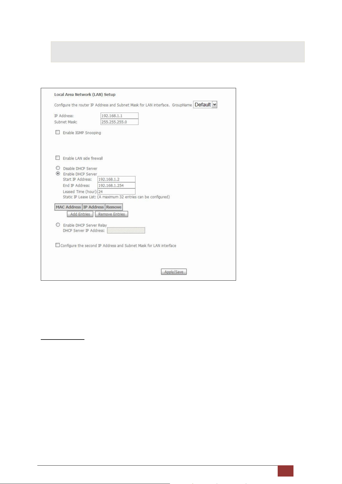
5.3 LAN
Configure the LAN interface settings and then click Apply/Save.
Consult the field descriptions below for more details.
GroupName: Select an Interface Group.
1st LAN INTERFACE
IP Address: Enter the IP address for the LAN port.
Subnet Mask: Enter the subnet mask for the LAN port.
Enable IGMP Snooping: Enable by ticking the checkbox .
Standard Mode: In standard mode, multicast traffic will flood to all bridge ports when no client
subscribes to a multicast group – even if IGMP snooping is enabled.
Blocking Mode: In blocking mode, the multicast data traffic will be blocked and not flood to all
bridge ports when there are no client subscriptions to any multicast group.
Proscend 130 ADSL2+/VDSL2 WLAN Router User Manual V0.02 36
Page 38
Enable LAN side firewall: Enable by ticking the checkbox .
DHCP Server: To enable DHCP, select Enable DHCP server and enter Start and End IP addresses and the
Leased Time. This setting configures the router to automatically assign IP, default gateway
and DNS server addresses to every PC on your LAN.
Static IP Lease List:
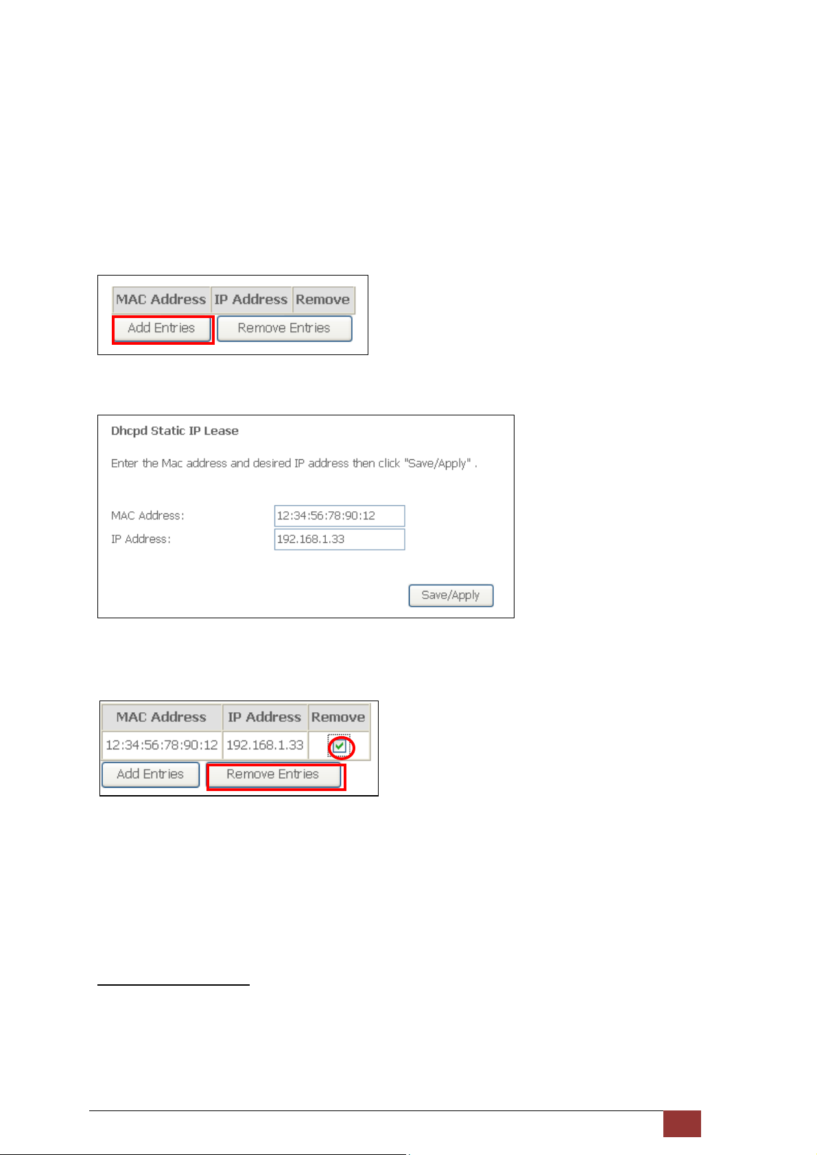
To add an entry, enter MAC address and Static IP and then click Save/Apply.
A maximum of 32 entries can be configured.
To remove an entry, tick the corresponding checkbox in the Remove column and then click the Remove
Entries button, as shown below.
DHCP Server Relay: Enable with checkbox and enter DHCP Server IP address.
This allows the Router to relay the DHCP packets to the remote DHCP server. The
remote DHCP server will provide the IP address. This option is hidden if NAT is
enabled or when the router is configured with only one Bridge PVC.
2ND LAN INTERFACE
To configure a secondary IP address, tick the checkbox outlined below.
Proscend 130 ADSL2+/VDSL2 WLAN Router User Manual V0.02 37
Page 39
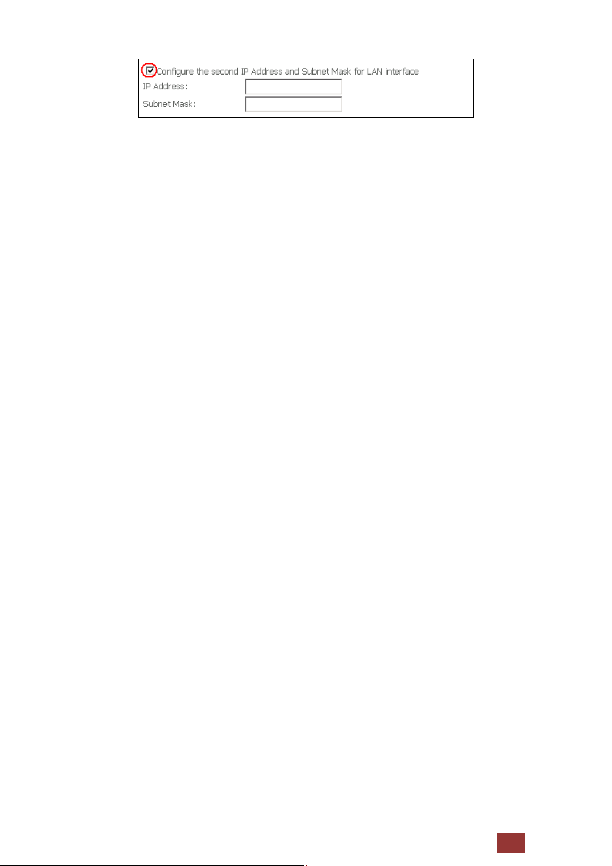
IP Address: Enter the secondary IP address for the LAN port.
Subnet Mask: Enter the secondary subnet mask for the LAN port.
Proscend 130 ADSL2+/VDSL2 WLAN Router User Manual V0.02 38
Page 40
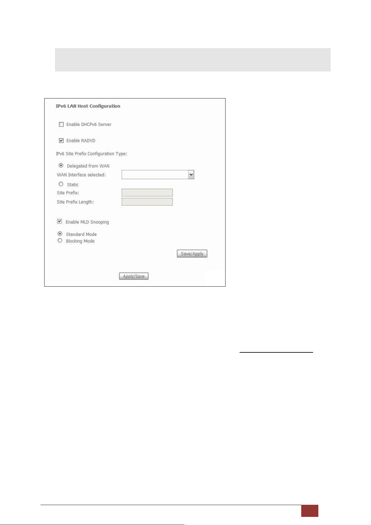
5.4 IPv6 LAN Host
Configure the IPv6 LAN Host options (see below) and then click Save/Apply.
DHCPv6 Server: To enable DHCP for IPv6, select the Enable DHCPv6 server checkbox . This setting
enables the router to assign IP settings to every IPv6-capable LAN device (IPv6 clients).
RADVD: Select the checkbox to enable the Router ADVertisement Daemon. This provides information
that IPv6 clients can use for auto-configuration according to the Neighbour Discovery for IPv6
protocol (RFC2461).
IPv6 Site Prefix: This setting can be delegated from a WAN Interface or assigned statically.
Enable MLD Snooping: Enable by ticking the checkbox .
Standard Mode: In standard mode, multicast traffic will flood to all bridge ports
when no client subscribes to a multicast group – even if snooping is enabled.
Blocking Mode: In blocking mode, the multicast data traffic will be blocked and not
flood to all bridge ports when there are no client subscriptions to any multicast group.
Proscend 130 ADSL2+/VDSL2 WLAN Router User Manual V0.02 39
Page 41
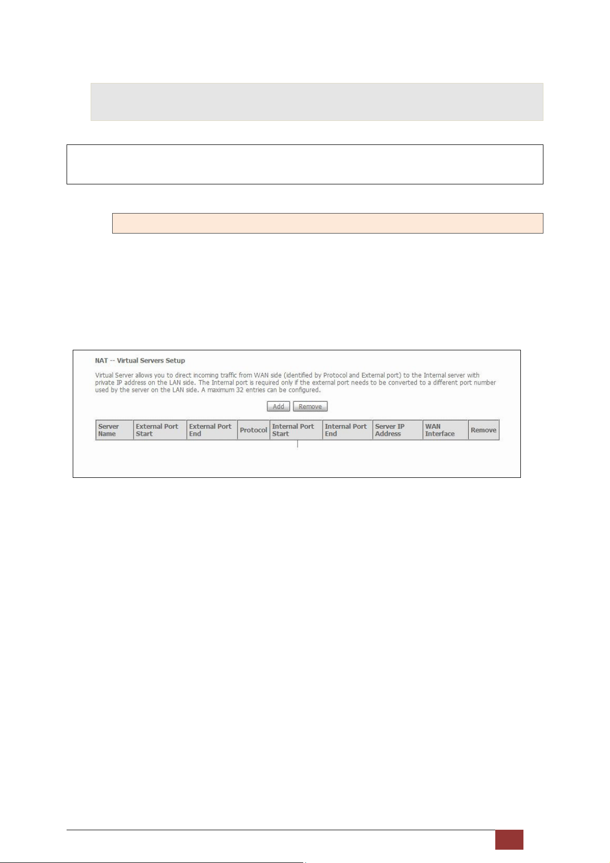
5.5 NAT
To display this option, NAT must be enabled in at least one PVC shown on the Advanced Setup- WAN screen.
NAT is not an available option in Bridge mode.
5.5.1 Virtual Servers
Virtual Servers allow you to direct incoming traffic from the WAN side (identified by Protocol and External port)
to the Internal server with private IP addresses on the LAN side. The Internal port is required only if the
external port needs to be converted to a different port number used by the server on the LAN side.
A maximum of 32 entries can be configured.
To add a Virtual Server, click Add. The following will be displayed.
Proscend 130 ADSL2+/VDSL2 WLAN Router User Manual V0.02 40
Page 42
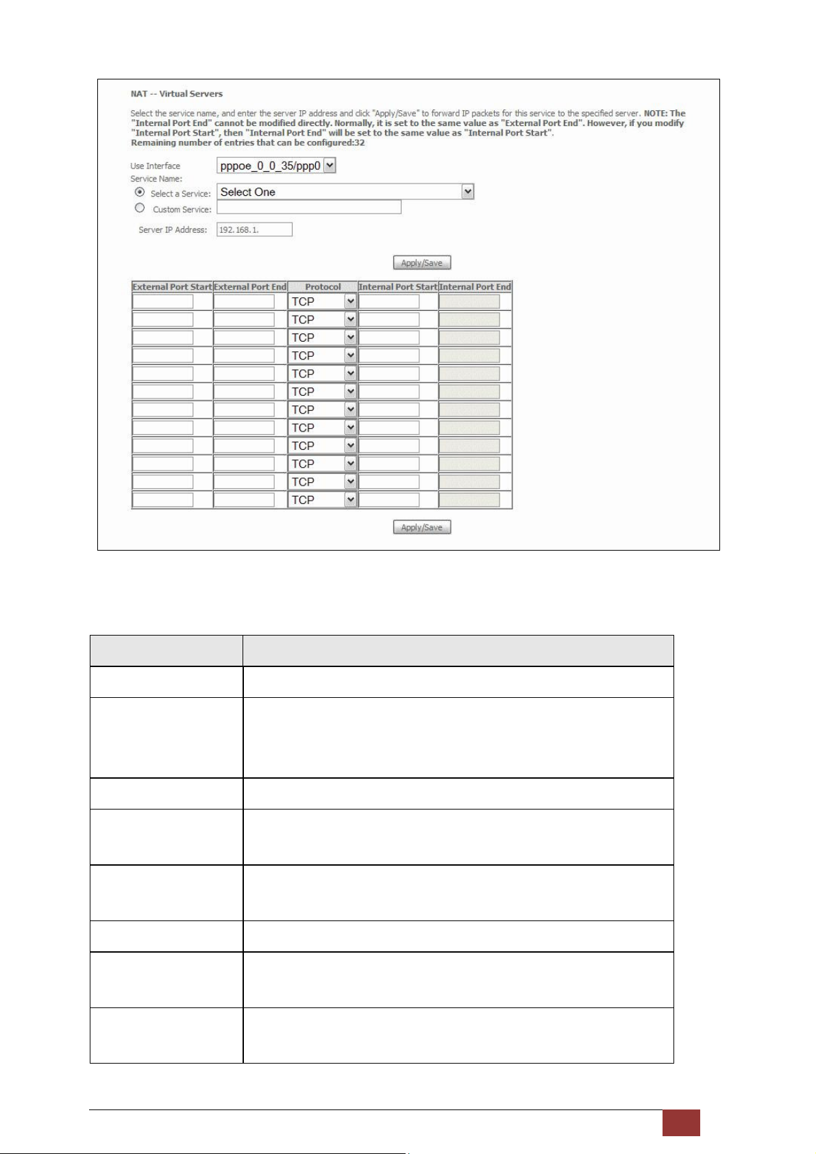
Consult the table below for field and header descriptions.
Field/Header Description
Use Interface Select a WAN interface from the drop-down box.
Select a Service
Or
Custom Service
Server IP Address Enter the IP address for the server.
External Port Start Enter the starting external port number (when you select Custom Server).
External Port End Enter the ending external port number (when you select Custom Server).
Protocol TCP, TCP/UDP, or UDP.
Internal Port Start Enter the internal port starting number (when you select Custom Server).
Internal Port End Enter the internal port ending number (when you select Custom Server).
User should select the service from the list.
Or
User can enter the name of their choice.
When a service is selected, the port ranges are automatically configured.
When a service is selected, the port ranges are automatically configured.
When a service is selected the port ranges are automatically configured
When a service is selected, the port ranges are automatically configured.
Proscend 130 ADSL2+/VDSL2 WLAN Router User Manual V0.02 41
Page 43
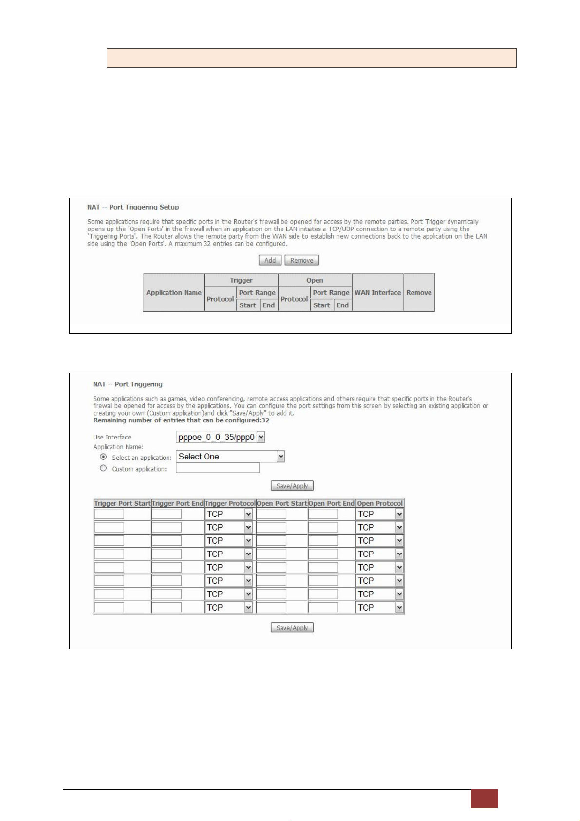
5.5.2 Port Triggering
Some applications require that specific ports in the firewall be opened for access by the remote parties. Port
Triggers dynamically 'Open Ports' in the firewall when an application on the LAN initiates a TCP/UDP
connection to a remote party using the 'Triggering Ports'. The Router allows the remote party from the WAN
side to establish new connections back to the application on the LAN side using the 'Open Ports'. A maximum
32 entries can be configured.
To add a Trigger Port, click Add. The following will be displayed.
Proscend 130 ADSL2+/VDSL2 WLAN Router User Manual V0.02 42
Page 44

Consult the table below for field and header descriptions.
Field/Header Description
Use Interface Select a WAN interface from the drop-down box.
Select an Application
Or
Custom Application
Trigger Port Start Enter the starting trigger port number (when you select custom
Trigger Port End Enter the ending trigger port number (when you select custom
Trigger Protocol TCP, TCP/UDP, or UDP.
Open Port Start Enter the starting open port number (when you select custom
Open Port End Enter the ending open port number (when you select custom
User should select the application from the list.
Or
User can enter the name of their choice.
application). When an application is selected, the port ranges are
automatically configured.
application). When an application is selected, the port ranges are
automatically configured.
application). When an application is selected, the port ranges are
automatically configured.
application). When an application is selected, the port ranges are
automatically configured.
Open Protocol TCP, TCP/UDP, or UDP.
Proscend 130 ADSL2+/VDSL2 WLAN Router User Manual V0.02 43
Page 45
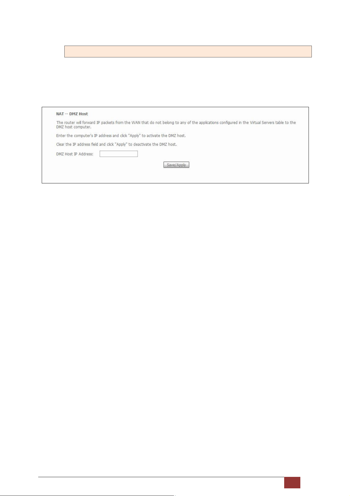
5.5.3 DMZ Host
The DSL router will forward IP packets from the WAN that do not belong to any of the applications configured
in the Virtual Servers table to the DMZ host computer.
To Activate the DMZ host, enter the DMZ host IP address and click Save/Apply.
To Deactivate the DMZ host, clear the IP address field and click Save/Apply.
Proscend 130 ADSL2+/VDSL2 WLAN Router User Manual V0.02 44
Page 46
5.6 Security
To display this function, you must enable the firewall feature in WAN Setup.
For detailed descriptions, with examples, please refer to Appendix chapter.
5.6.1 IP Filtering
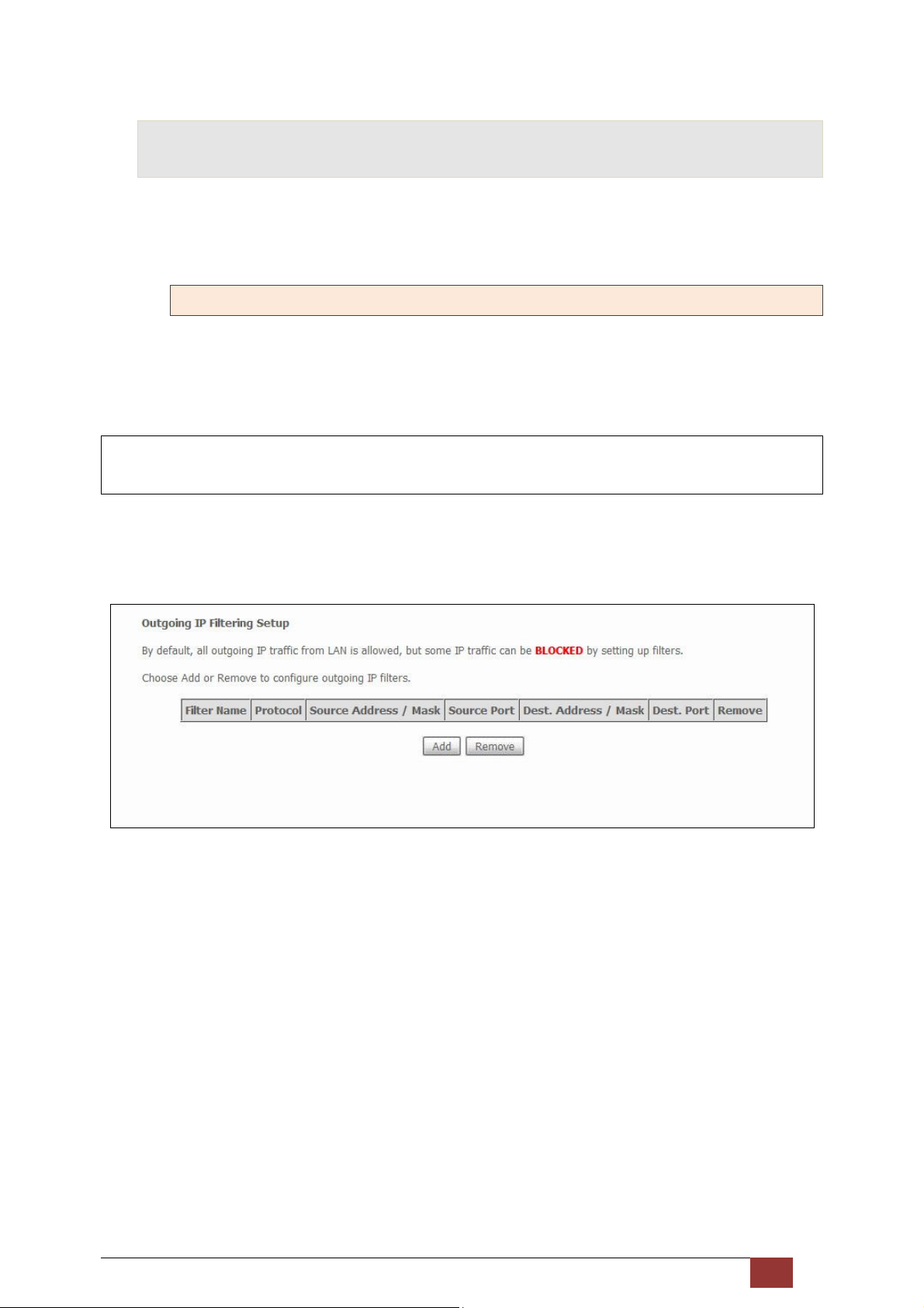
This screen sets filter rules that limit IP traffic (Outgoing/Incoming). Multiple filter rules can be set and each
applies at least one limiting condition. For individual IP packets to pass the filter all conditions must be fulfilled.
NOTE: This function is not available when in bridge mode. Instead, MAC Filtering performs a similar
function.
OUTGOING IP FILTER
By default, all outgoing IP traffic is allowed, but IP traffic can be blocked with filters.
To add a filter (to block some outgoing IP traffic), click the Add button.
On the following screen, enter your filter criteria and then click Apply/Save.
Proscend 130 ADSL2+/VDSL2 WLAN Router User Manual V0.02 45
Page 47
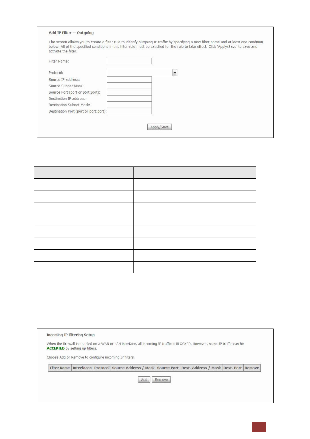
Consult the table below for field descriptions.
Field Description
Filter Name The filter rule label
Protocol TCP, TCP/UDP, UDP, or ICMP.
Source IP address Enter source IP address.
Source Subnet Mask Enter source subnet mask.
Source Port (port or port:port) Enter source port number or range.
Destination IP address Enter destination IP address.
Destination Subnet Mask Enter destination subnet mask.
Destination Port (port or port:port) Enter destination port number or range.
INCOMING IP FILTER
By default, all incoming IP traffic is blocked, but IP traffic can be allowed with filters.
Proscend 130 ADSL2+/VDSL2 WLAN Router User Manual V0.02 46
Page 48
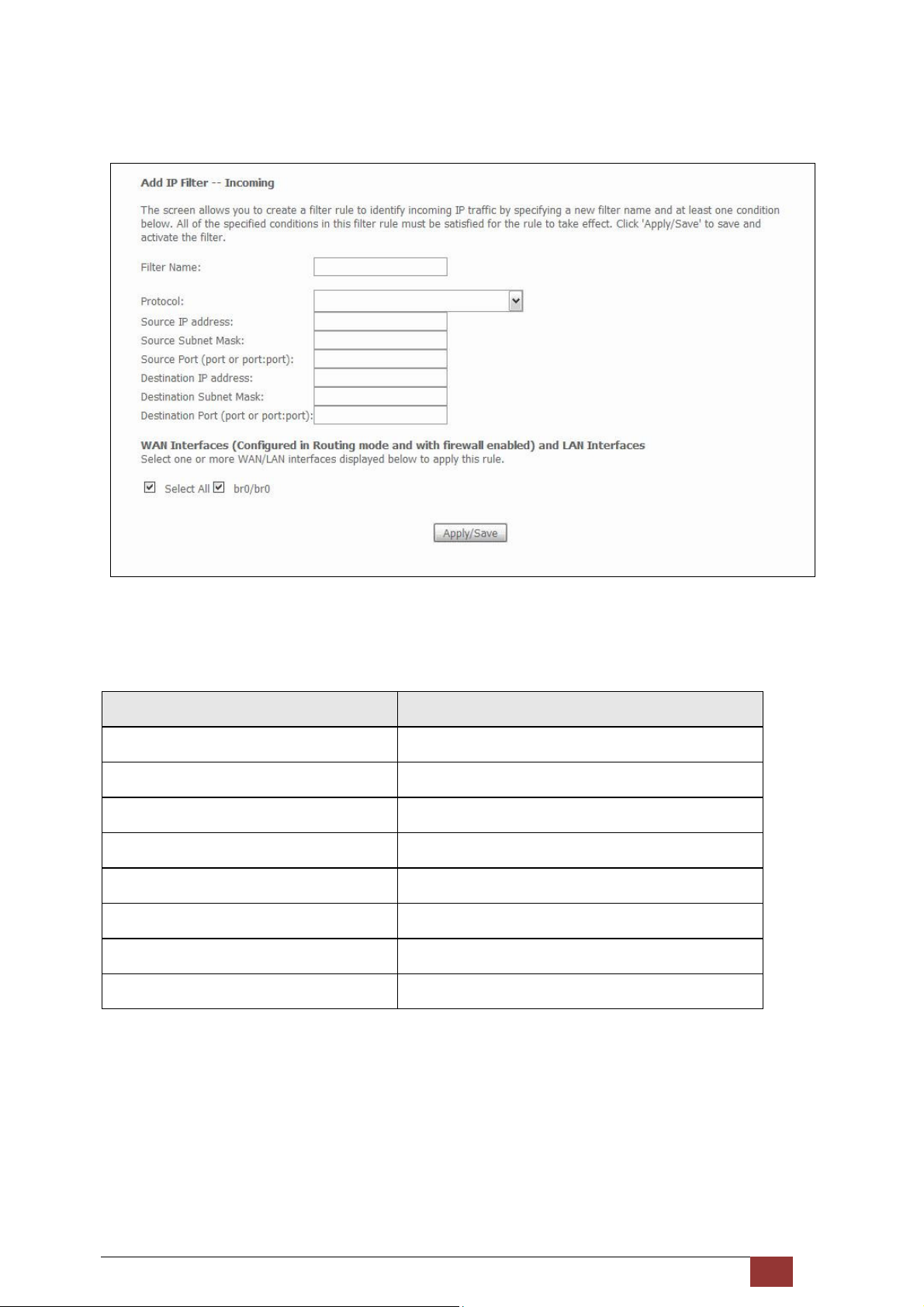
To add a filter (to allow incoming IP traffic), click the Add button.
On the following screen, enter your filter criteria and then click Apply/Save.
Consult the table below for field descriptions.
Field Description
Filter Name The filter rule label
Protocol TCP, TCP/UDP, UDP, or ICMP.
Source IP address Enter source IP address.
Source Subnet Mask Enter source subnet mask.
Source Port (port or port:port) Enter source port number or range.
Destination IP address Enter destination IP address.
Destination Subnet Mask Enter destination subnet mask.
Destination Port (port or port:port) Enter destination port number or range.
At the bottom of this screen, select the WAN and LAN Interfaces to which the filter rule will apply. You may
select all or just a subset. WAN interfaces in bridge mode or without firewall enabled are not available.
Proscend 130 ADSL2+/VDSL2 WLAN Router User Manual V0.02 47
Page 49
5.6.2 MAC Filtering
NOTE: This option is only available in bridge mode. Other modes use IP Filtering to perform a similar
function.
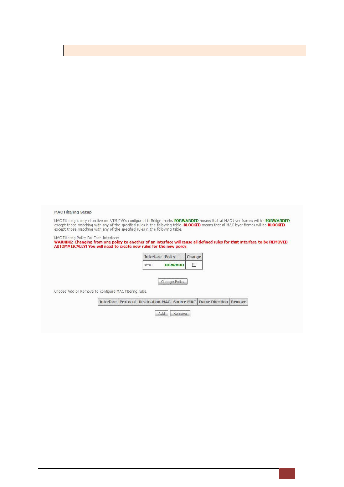
Each network device has a unique 48-bit MAC address. This can be used to filter (block or forward) packets
based on the originating device. MAC filtering policy and rules for the Proscend 130 can be set according to the
following procedure.
The MAC Filtering Global Policy is defined as follows:
FORWARDED: Means that all MAC layer frames will be FORWARDED except those matching the MAC filter
rules.
BLOCKED: Means that all MAC layer frames will be BLOCKED except those matching the MAC filter rules. The
default MAC Filtering Global policy is FORWARDED. It can be changed by clicking the Change Policy button.
Choose Add or Remove to configure MAC filtering rules. The following screen will appear when you click Add.
Create a filter to identify the MAC layer frames by specifying at least one condition below. If multiple
conditions are specified, all of them must be met. Click Save/Apply to save and activate the filter rule.
Proscend 130 ADSL2+/VDSL2 WLAN Router User Manual V0.02 48
Page 50
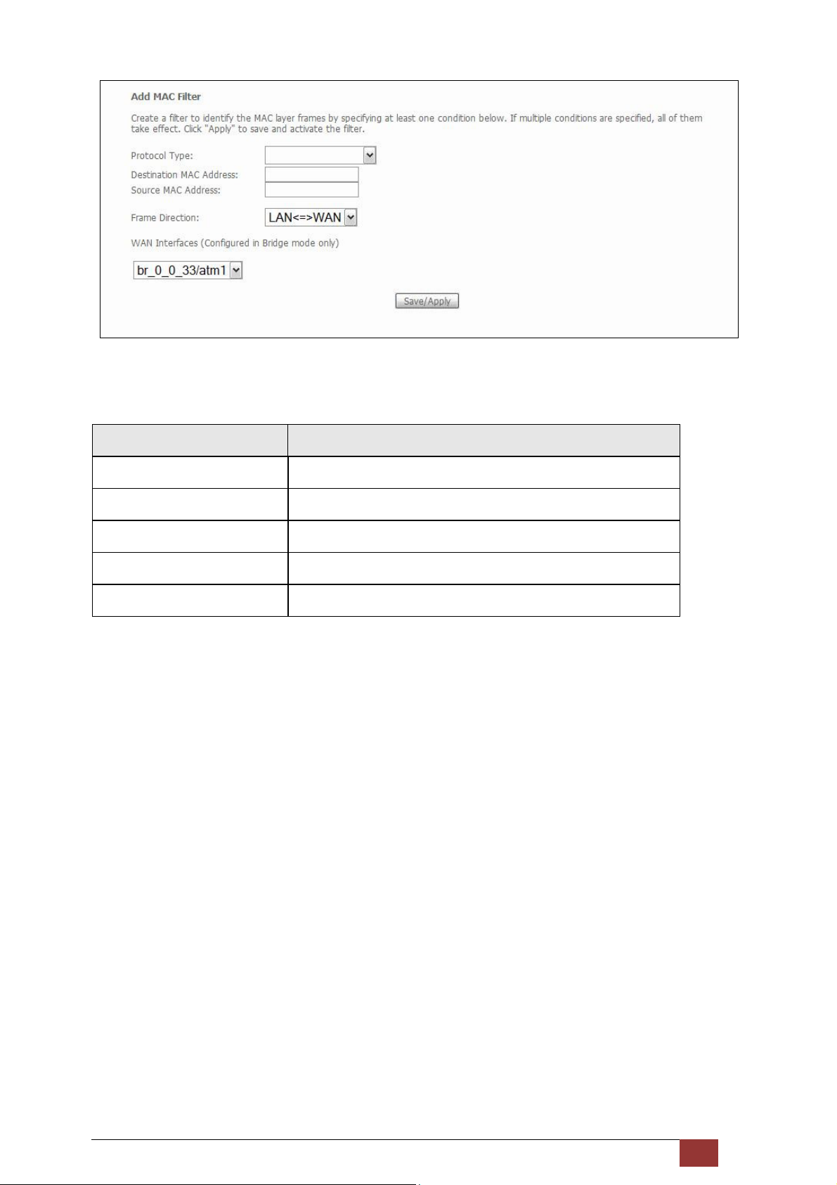
Consult the table below for detailed field descriptions.
Field Description
Protocol Type PPPoE, IPv4, IPv6, AppleTalk, IPX, NetBEUI, IGMP
Destination MAC Address Defines the destination MAC address
Source MAC Address Defines the source MAC address
Frame Direction Select the incoming/outgoing packet interface
WAN Interfaces Applies the filter to the selected bridge interface.
Proscend 130 ADSL2+/VDSL2 WLAN Router User Manual V0.02 49
Page 51
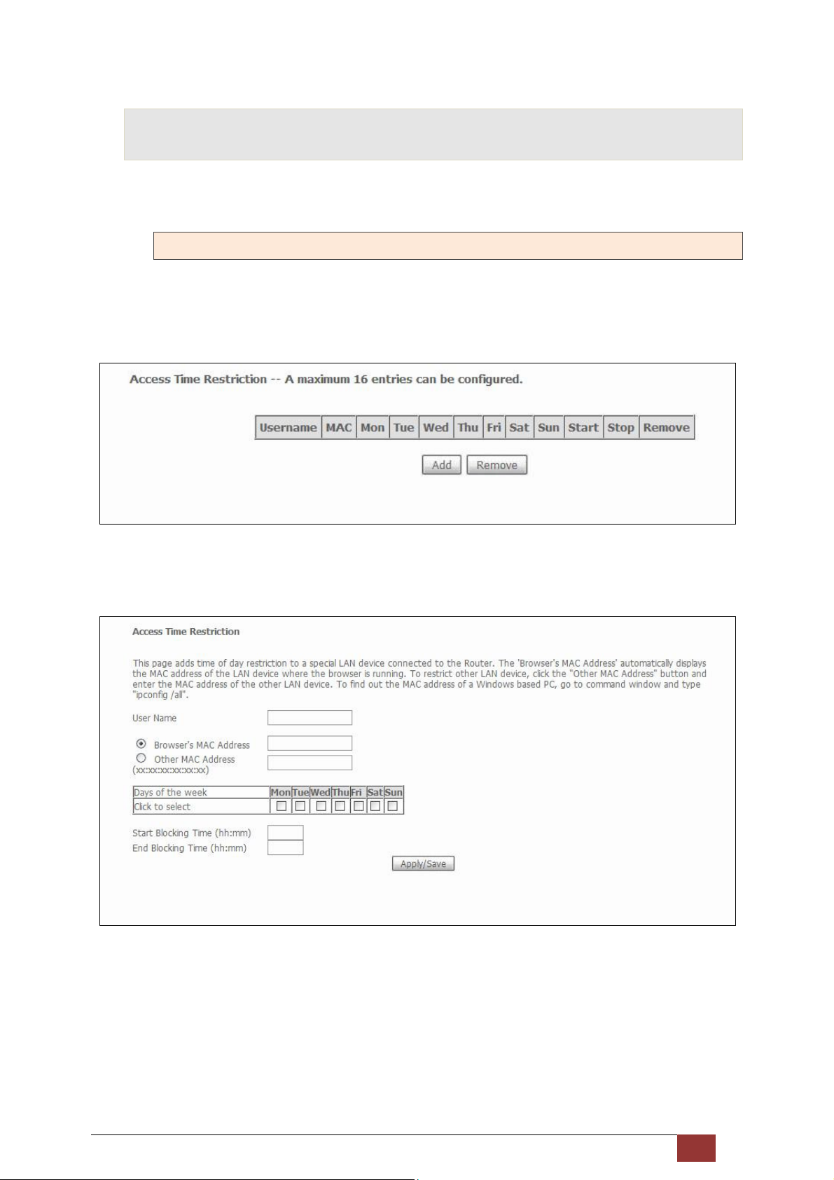
5.7 Parental Control
This selection provides WAN access control functionality.
5.7.1 Time Restriction
This feature restricts access from a LAN device to an outside network through the device on selected days at
certain times. Make sure to activate the Internet Time server synchronization, so that the scheduled times
match your local time.
Click Add to display the following screen.
See below for field descriptions. Click Apply/Save to add a time restriction.
User Name: A user-defined label for this restriction.
Browser's MAC Address: MAC address of the PC running the browser.
Other MAC Address: MAC address of another LAN device.
Days of the Week: The days the restrictions apply.
Proscend 130 ADSL2+/VDSL2 WLAN Router User Manual V0.02 50
Page 52
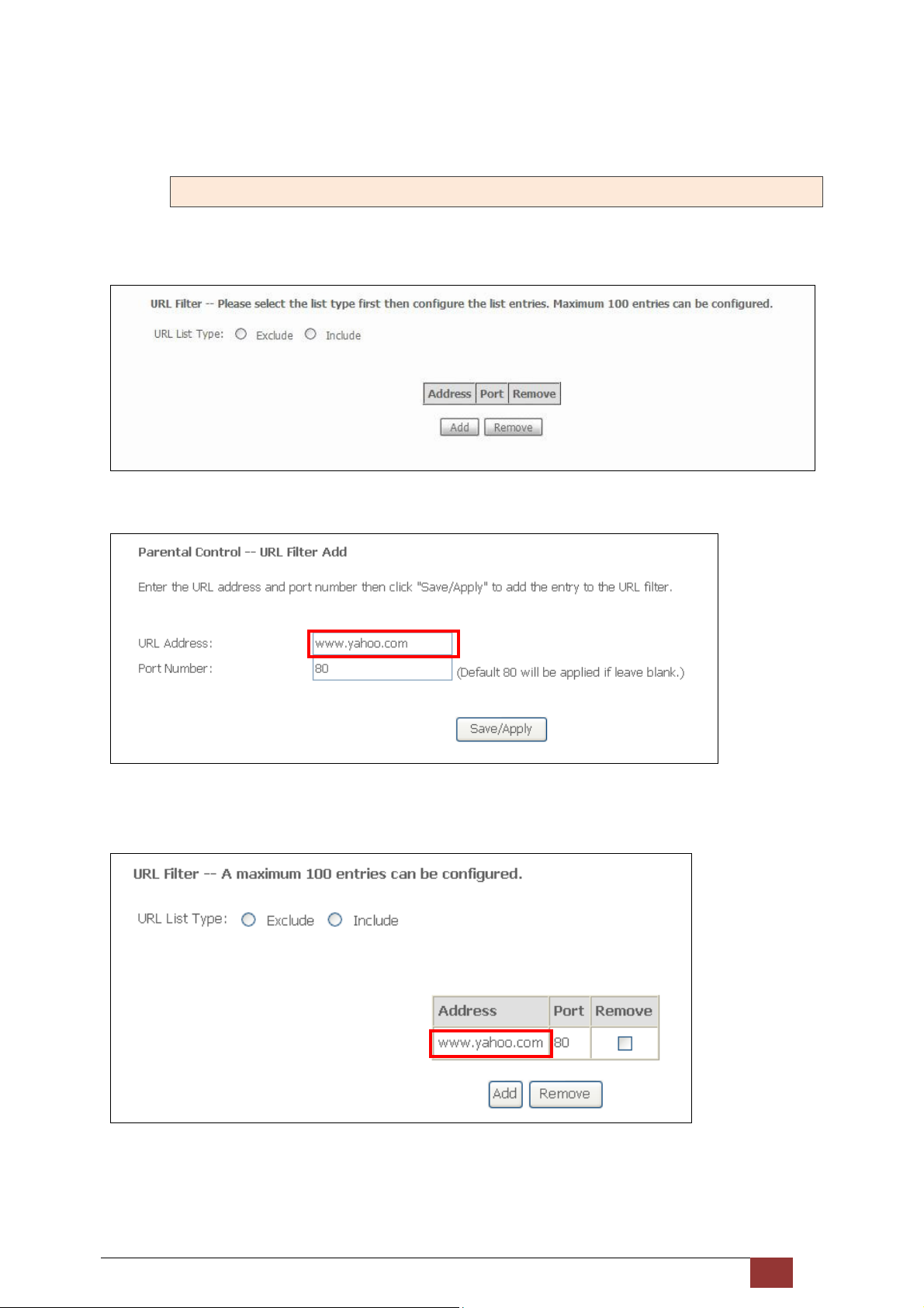
Start Blocking Time: The time the restrictions start.
End Blocking Time: The time the restrictions end.
5.7.2 URL Filter
This screen allows for the creation of a filter rule for access rights to websites based on their URL address and
port number.
Click Add to display the following screen.
Enter the URL address and port number then click Save/Apply to add the entry to the URL filter. URL
Addresses begin with “www”, as shown in this example.
A maximum of 100 entries can be added to the URL Filter list.
Tick the Exclude radio button to deny access to the websites listed.
Tick the Include radio button to restrict access to only those listed websites.
Proscend 130 ADSL2+/VDSL2 WLAN Router User Manual V0.02 51
Page 53

5.8 Quality of Service (QoS)
NOTE: QoS must be enabled in at least one PVC to display this option.
5.8.1 Queue Management Configuration
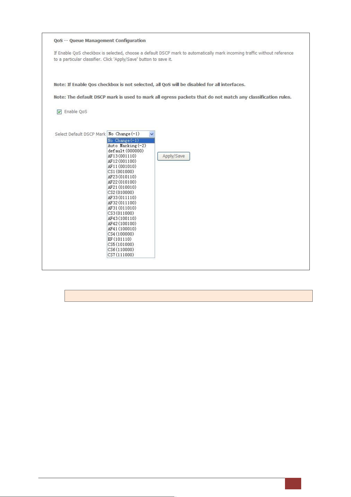
To Enable QoS tick the checkbox and select a Default DSCP Mark.
Click Apply/Save to activate QoS.
QoS and DSCP Mark are defined as follows:
Quality of Service (QoS): This provides different priority to different users or data flows, or guarantees a
certain level of performance to a data flow in accordance with requests from Queue Prioritization.
Default Differentiated Services Code Point (DSCP) Mark: This specifies the per hop behavior for a given flow of
packets in the Internet Protocol (IP) header that do not match any other QoS rule.
Proscend 130 ADSL2+/VDSL2 WLAN Router User Manual V0.02 52
Page 54
5.8.2 Queue Configuration
This function follows the Differentiated Services rule of IP QoS. You can create a new Queue entry by clicking
the Add button. Enable and assign an interface and precedence on the next screen. Click Save/Reboot on this
screen to activate it.
Proscend 130 ADSL2+/VDSL2 WLAN Router User Manual V0.02 53
Page 55
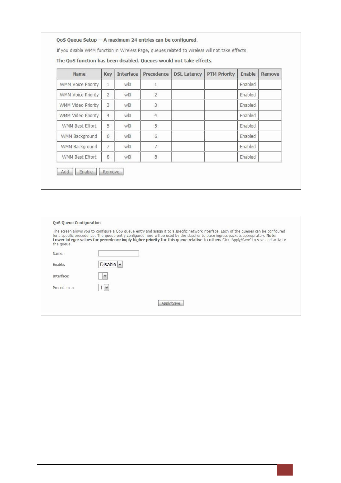
Click Enable to activate the QoS Queue. Click Add to display the following screen.
Name: Identifier for this Queue entry.
Enable: Enable/Disable the Queue entry.
Interface: Assign the entry to a specific network interface (QoS enabled).
Precedence: Configure precedence for the Queue entry. Lower integer values for precedence imply higher
priority for this entry relative to others.
Proscend 130 ADSL2+/VDSL2 WLAN Router User Manual V0.02 54
Page 56
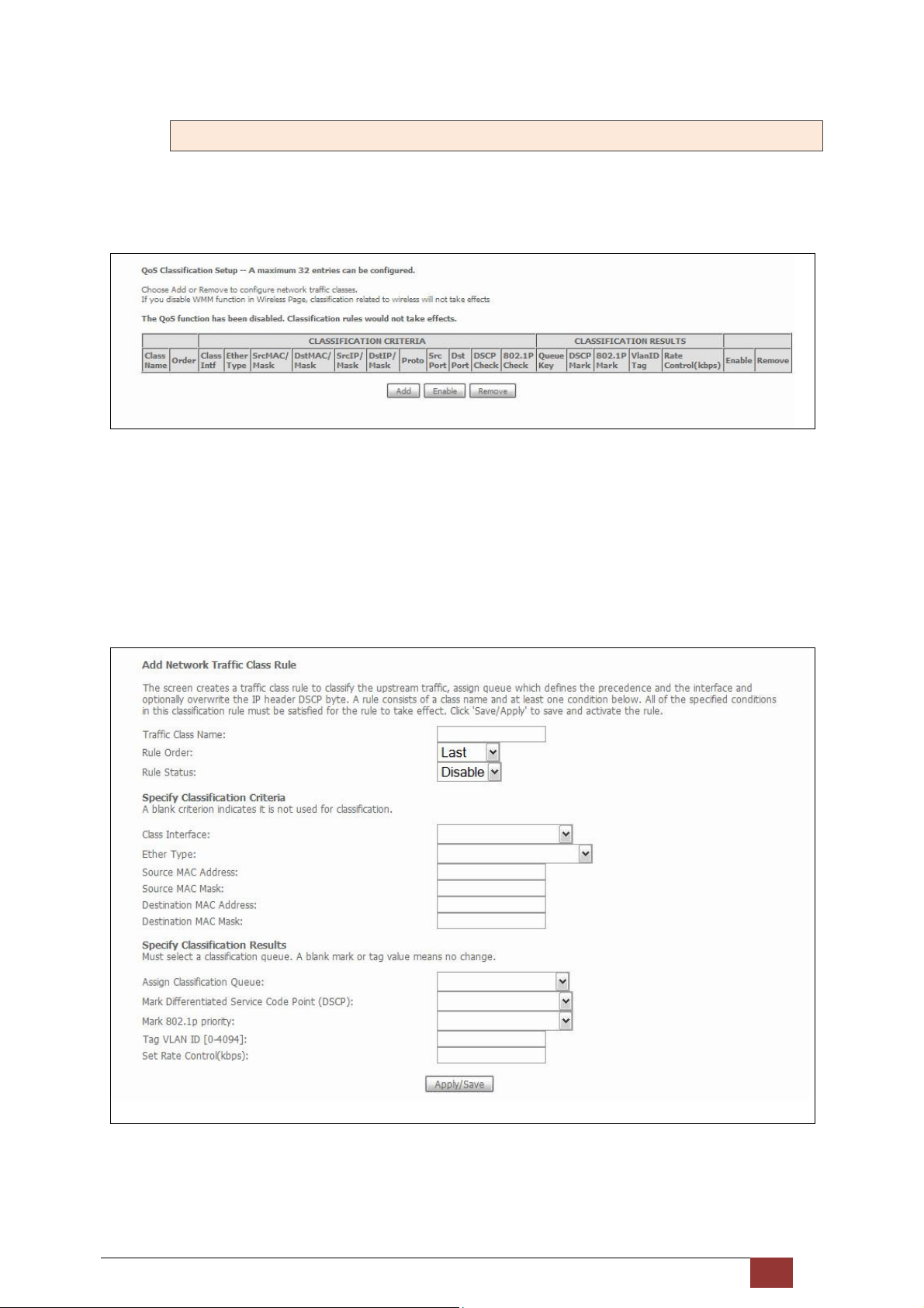
5.8.3 QoS Classification
The network traffic classes are listed in the following table.
Click Add to configure a network traffic class rule and Enable to activate it. To delete an entry from the list,
click Remove.
This screen creates a traffic class rule to classify the upstream traffic, assign queuing priority and optionally
overwrite the IP header DSCP byte. A rule consists of a class name and at least one logical condition. All the
conditions specified in the rule must be satisfied for it to take effect.
Proscend 130 ADSL2+/VDSL2 WLAN Router User Manual V0.02 55
Page 57
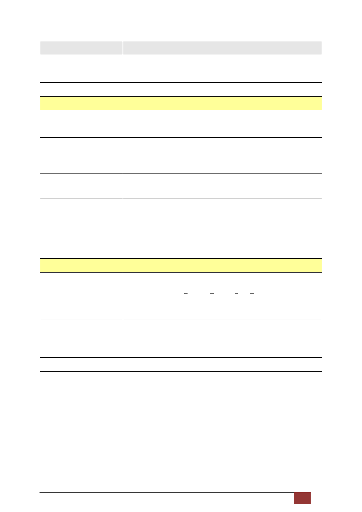
Field Description
Traffic Class Name Enter a name for the traffic class.
Rule Order Last is the only option.
Rule Status Disable or enable the rule.
Classification Criteria
Class Interface Select an interface (i.e. Local, eth1, eth2, eth3, eth4, wl0)
Ether Type Set the Ethernet type (e.g. IP, ARP, IPv6 etc.).
Source MAC Address A packet belongs to SET-1, if a binary-AND of its source MAC address with the
Source MAC Mask is equal to the binary-AND of the Source MAC Mask and
this field.
Source MAC Mask This is the mask used to decide how many bits are checked in Source MAC
Address.
Destination MAC Address A packet belongs to SET-1 then the result that the Destination MAC Address
of its header binary-AND to the Destination MAC Mask must equal to the
result that this field binary-AND to the Destination MAC Mask.
Destination MAC Mask This is the mask used to decide how many bits are checked in Destination
MAC Address.
Classification Results
Assign Classification Queue The queue configurations are presented in this format:
“Interfacename&Prece P&Queue Q” where P and Q are the Precedence and
Queue Key values for the corresponding Interface as listed on the Queue
Config screen.
Mark Differentiated Service
Code Point
Mark 802.1p Priority Select between 0-7. Lower values have higher priority.
Tag VLAN ID Enter a 802.1Q VLAN ID tag [2-4094]
Set Rate Control The data transmission rate limit in kbps.
The selected Code Point gives the corresponding priority to packets that
satisfy the rule.
Proscend 130 ADSL2+/VDSL2 WLAN Router User Manual V0.02 56
Page 58
5.9 Routing
These following routing functions are accessed from this menu:
Default Gateway, Static Route, Policy Routing, RIP and IPv6 Static Route.
NOTE: In bridge mode, the RIP menu option is hidden while the other menu options are shown but
ineffective.
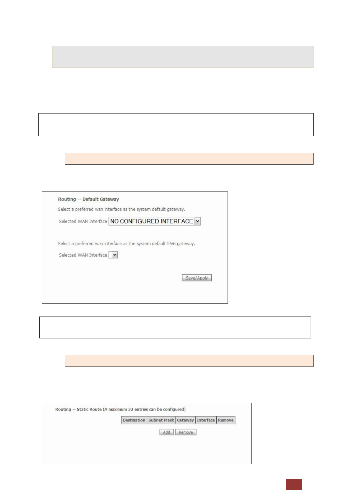
5.9.1 Default Gateway
Select WAN Interfaces as default gateways and then click Save/Apply.
NOTE: After enabling the Automatic Assigned Default Gateway, the device must be rebooted to activate
the assigned default gateway.
5.9.2 Static Route
This option allows for the configuration of static routes by destination IP.
Click Add to create a static route or click Remove to delete a static route.
Proscend 130 ADSL2+/VDSL2 WLAN Router User Manual V0.02 57
Page 59
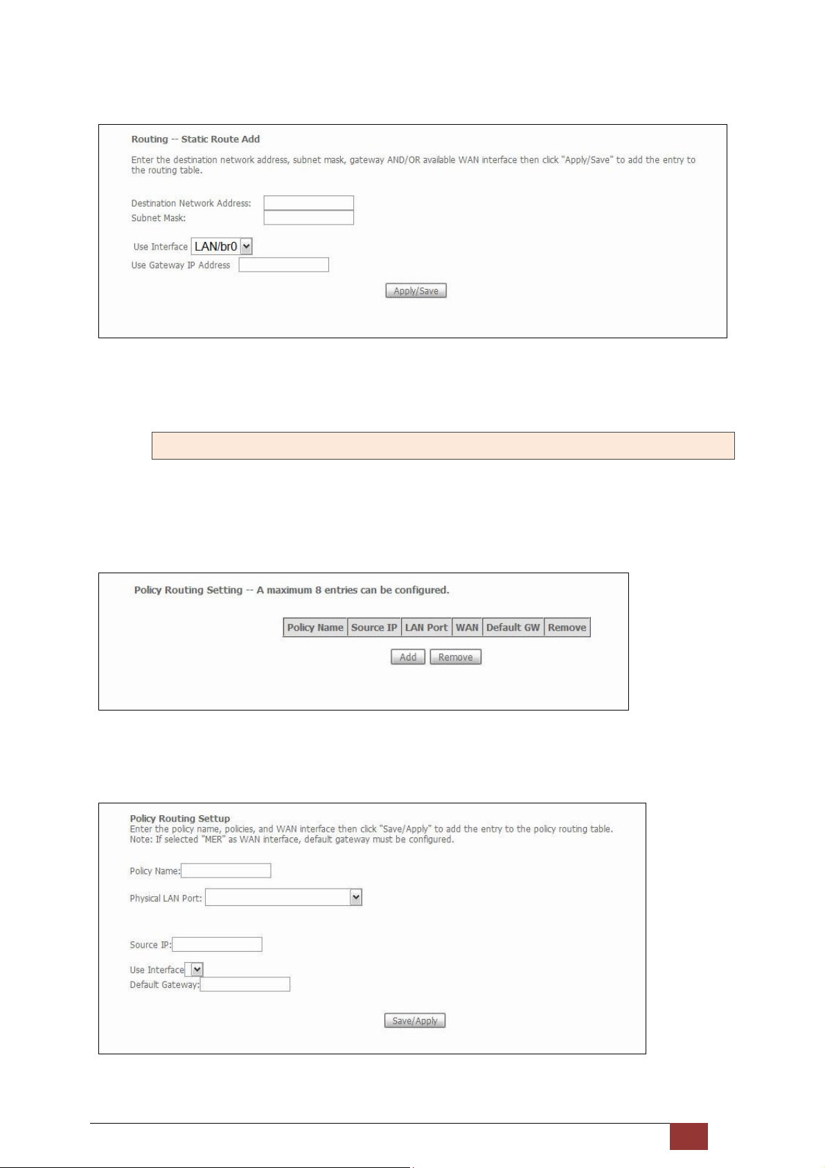
After clicking Add the following screen will display.
Enter Destination Network Address, Subnet Mask, Gateway IP Address, and/or WAN Interface before clicking
Apply/Save to add an entry to the routing table.
5.9.3 Policy Routing
This option allows for the configuration of static routes by policy.
Click Add to create a routing policy or Remove to delete one.
On the following screen, complete the form and click Save/Apply to create a policy.
Proscend 130 ADSL2+/VDSL2 WLAN Router User Manual V0.02 58
Page 60
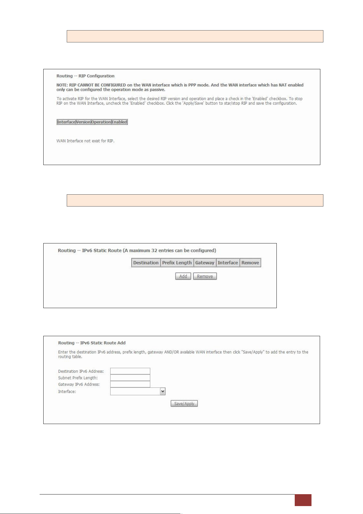
5.9.4 RIP
To activate RIP, configure the RIP version/operation mode and select the Enabled checkbox for at least one
WAN interface before clicking Save/Apply.
5.9.5 IPv6 Static Route
This option allows for the configuration of static routes by destination IP.
Click Add to create a static route or click Remove to delete a static route.
After clicking Add the following screen will display.
Enter Destination IPv6 Address, Subnet Prefix Length, Gateway IPv6 Address, and/or WAN Interface before
clicking Save/Apply to add a routing entry.
Proscend 130 ADSL2+/VDSL2 WLAN Router User Manual V0.02 59
Page 61
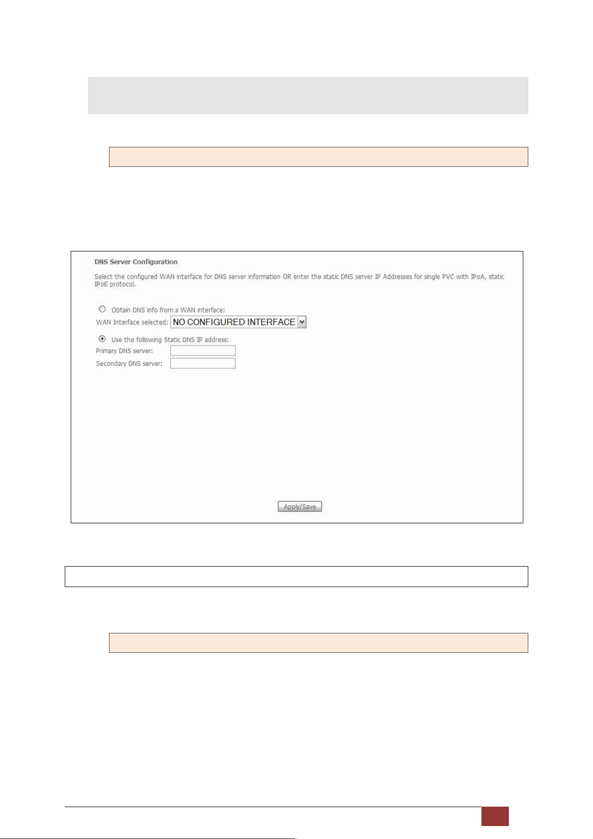
5.10 DNS
5.10.1 DNS Server
To obtain DNS information from a WAN interface, select the first radio button and then choose a WAN
interface from the drop-down box. For Static DNS, select the second radio button and enter the IP Address of
the primary (and secondary) DNS server(s). Click Apply/Save to save the new configuration.
NOTE: You must reboot the router to make the new configuration effective.
5.10.2 Dynamic DNS
The Dynamic DNS service allows you to map a dynamic IP address to a static hostname in any of many domains,
allowing the Proscend 130 to be more easily accessed from various locations on the Internet.
Proscend 130 ADSL2+/VDSL2 WLAN Router User Manual V0.02 60
Page 62
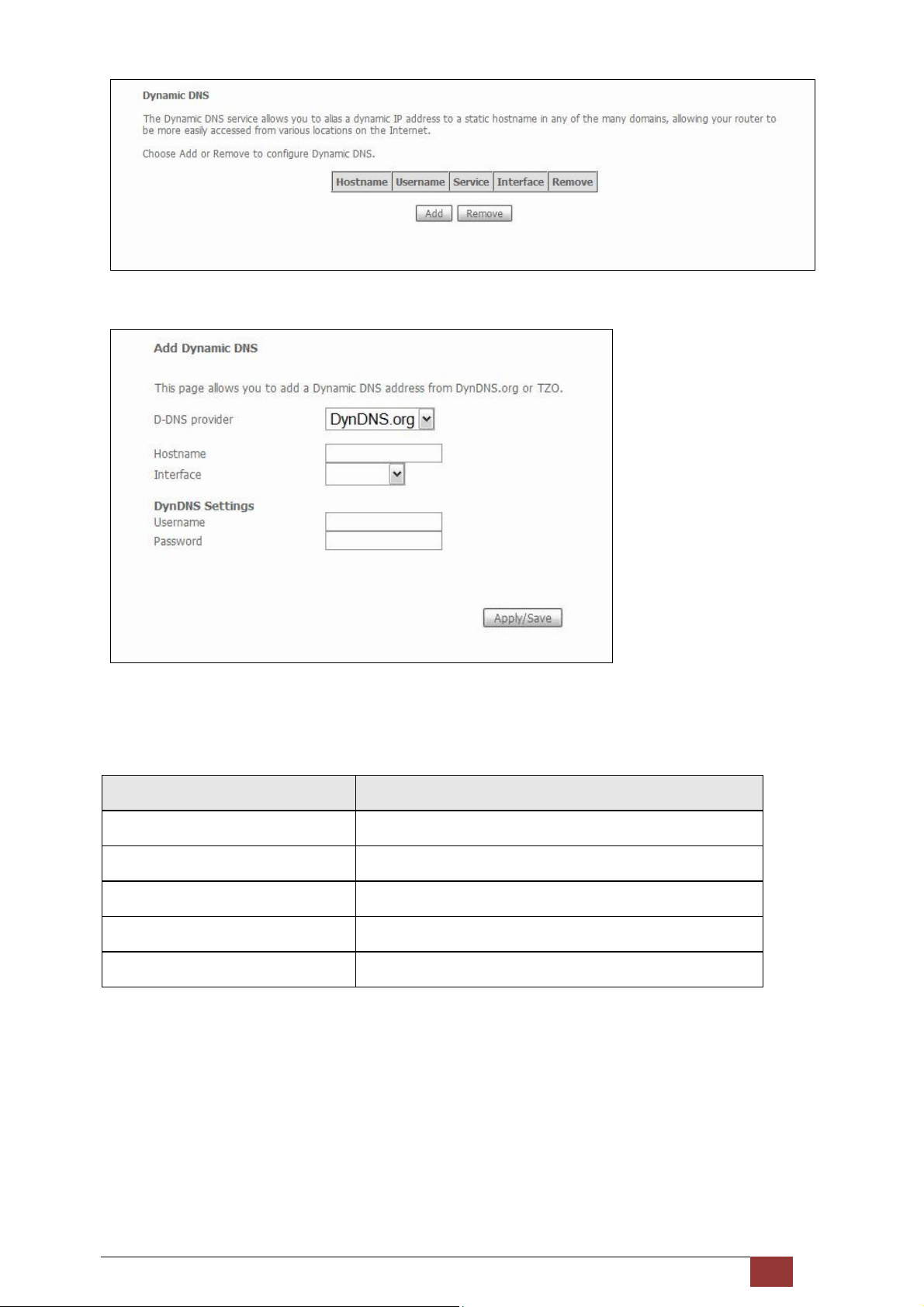
To add a dynamic DNS service, click Add. The following screen will display.
Consult the table below for field descriptions.
Field Description
D-DNS provider Select a dynamic DNS provider from the list
Hostname Enter the name of the dynamic DNS server
Interface Select the interface from the list
Username Enter the username of the dynamic DNS server
Password Enter the password of the dynamic DNS server
Proscend 130 ADSL2+/VDSL2 WLAN Router User Manual V0.02 61
Page 63
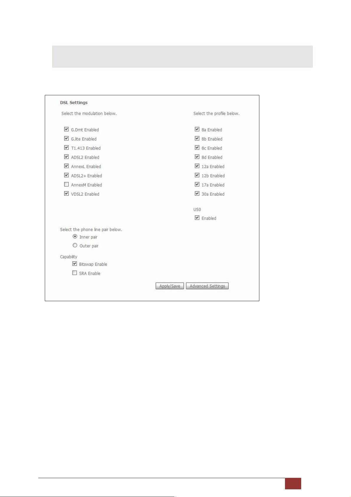
5.11 DSL
The DSL Settings screen allows for the selection of DSL modulation modes.
For optimum performance, the modes selected should match those of your ISP.
Proscend 130 ADSL2+/VDSL2 WLAN Router User Manual V0.02 62
Page 64
DSL Mode Data Transmission Rate - Mbps (Megabits per second)
G.Dmt Downstream: 12 Mbps Upstream: 1.3 Mbps
G.lite Downstream: 4 Mbps Upstream: 0.5 Mbps
T1.413 Downstream: 8 Mbps Upstream: 1.0 Mbps
ADSL2 Downstream: 12 Mbps Upstream: 1.0 Mbps
Annex L Supports longer loops but with reduced transmission rates
ADSL2+ Downstream: 24 Mbps Upstream: 1.0 Mbps
Annex M Downstream: 24 Mbps Upstream: 3.5 Mbps
VDSL2 Downstream: 100 Mbps Upstream: 60 Mbps
Options Description
Inner/Outer Pair Select the inner or outer pins of the twisted pair (RJ11 cable)
Bitswap Enable Enables adaptive handshaking functionality
SRA Enable Enables Seamless Rate Adaptation (SRA)
Profile Selection 8a, 8b, 8c, 8d, 12a, 12b, 17a, 30a, US0
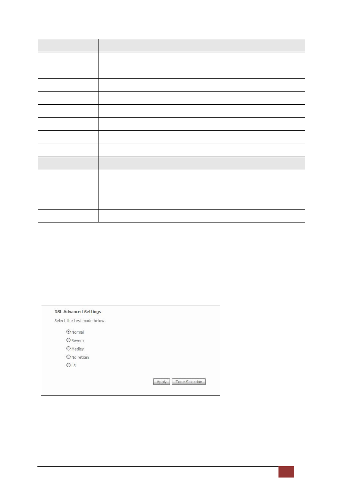
Advanced DSL Settings
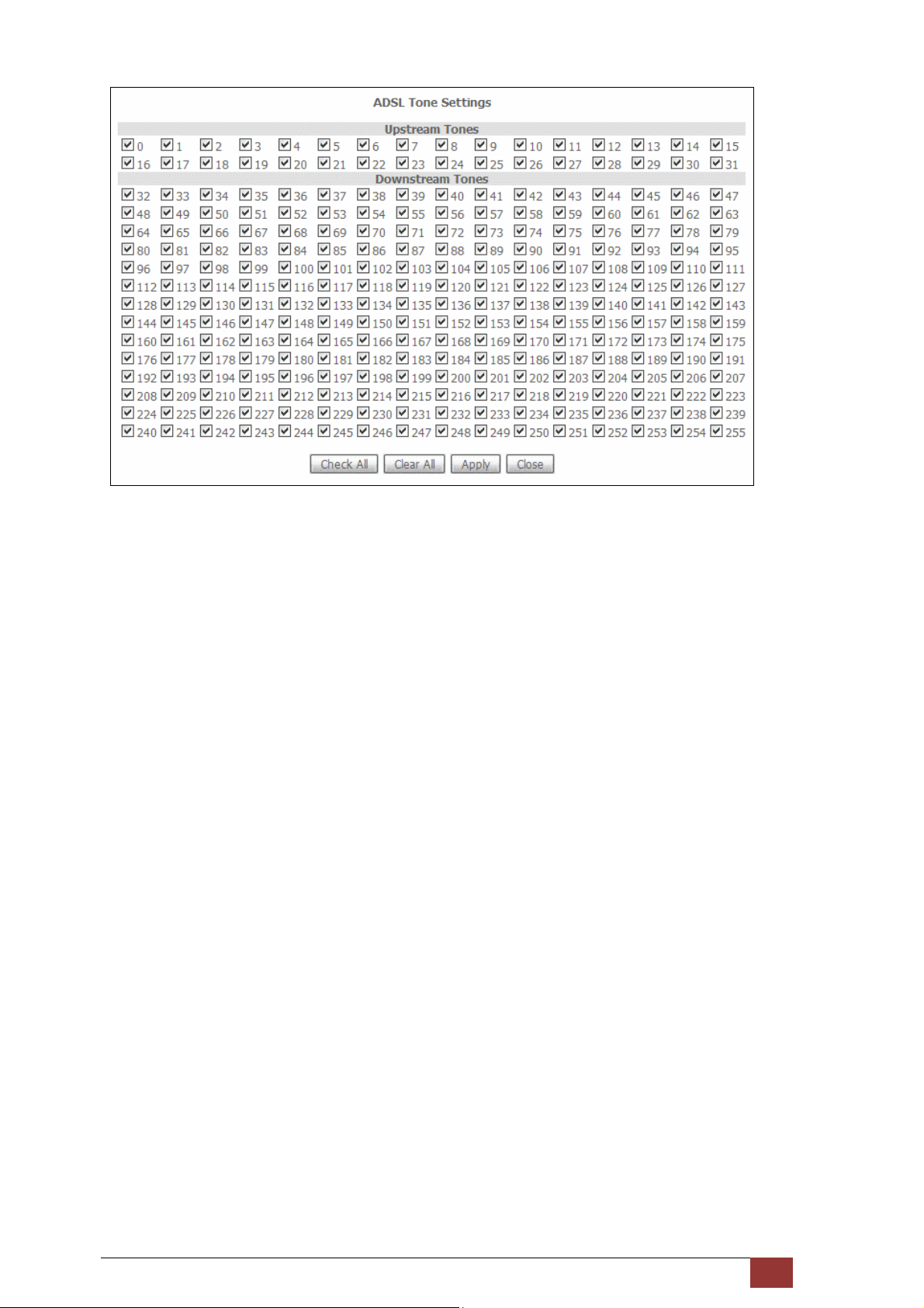
Click Advanced Settings to reveal additional options. On the following screen you can select a test mode or
modify tones by clicking Tone Selection. Click Apply to implement these settings and return to the previous
screen.
On this screen you select the tones you want activated, then click Apply and Close.
Proscend 130 ADSL2+/VDSL2 WLAN Router User Manual V0.02 63
Page 65
Proscend 130 ADSL2+/VDSL2 WLAN Router User Manual V0.02 64
Page 66
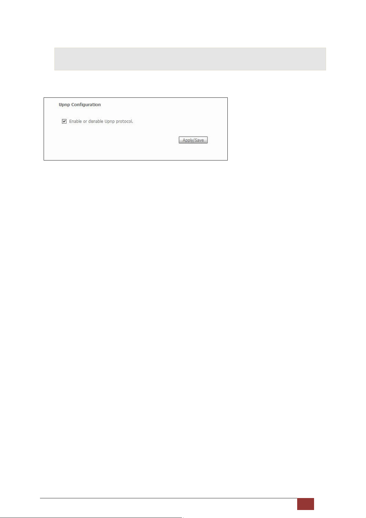
5.12 UPnP
Select the checkbox provided and click Apply/Save to enable UPnP protocol.
Proscend 130 ADSL2+/VDSL2 WLAN Router User Manual V0.02 65
Page 67
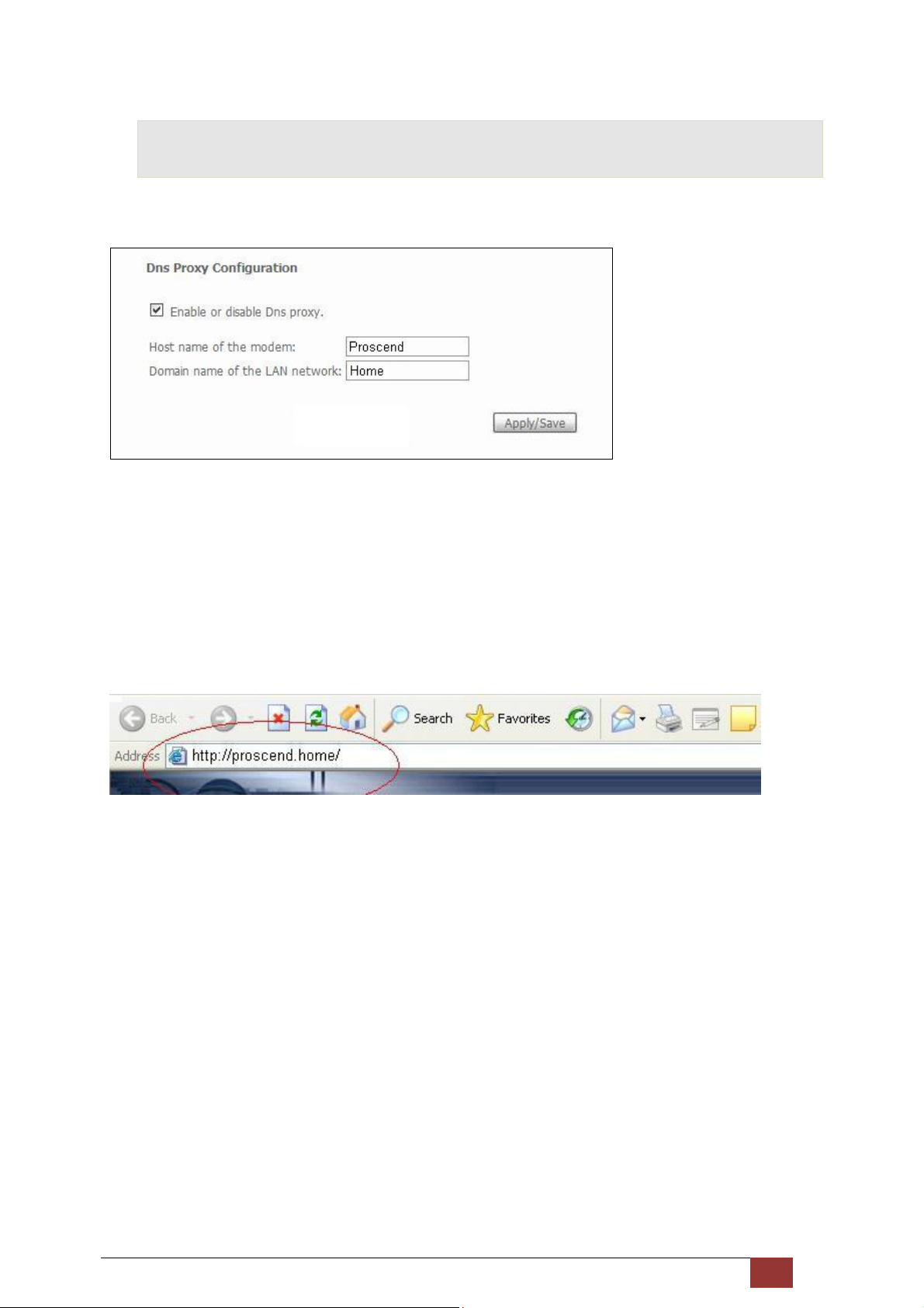
5.13 DNS Proxy
To enable DNS Proxy, select the corresponding checkbox and then enter Host and Domain names, as the
example shown below. Click Apply/Save to continue.
See below for further details.
The Host Name and Domain Name are combined to form a unique label that is mapped to the router IP address.
This can be used to access the WUI with a local name rather than by using the router IP address. The figure
below shows an example of this. In the browser address bar (circled in red) the prefix “http://" is added to the
local name “proscend.Home” [Host.Domain] for WUI access.
Proscend 130 ADSL2+/VDSL2 WLAN Router User Manual V0.02 66
Page 68
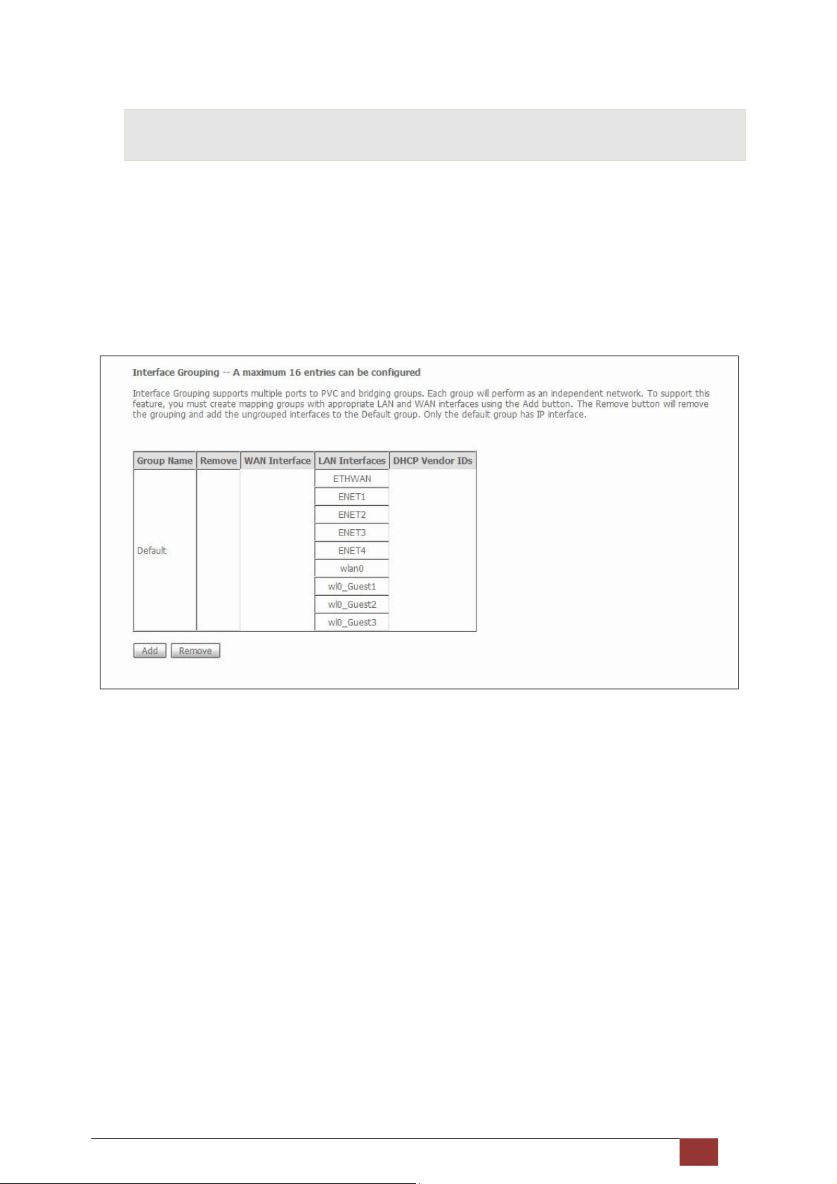
5.14 Interface Grouping
Interface Grouping supports multiple ports to PVC and bridging groups. Each group performs as an
independent network. To use this feature, you must create mapping groups with appropriate LAN and WAN
interfaces using the Add button.
The Remove button removes mapping groups, returning the ungrouped interfaces to the Default group. Only
the default group has an IP interface.
To add an Interface Group, click the Add button. The following screen will appear. It lists the available and
grouped interfaces. Follow the instructions shown here.
Proscend 130 ADSL2+/VDSL2 WLAN Router User Manual V0.02 67
Page 69
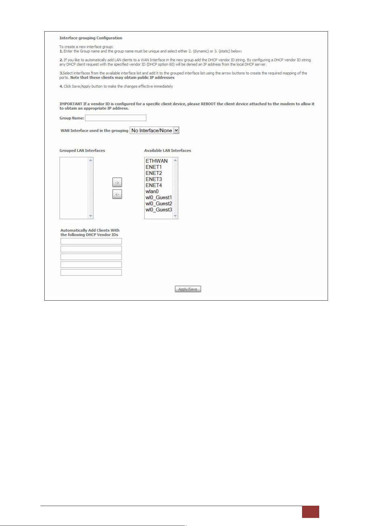
Automatically Add Clients With Following DHCP Vendor IDs:
Add support to automatically map LAN interfaces to PVC's using DHCP vendor ID (option 60). The local DHCP
server will decline and send the requests to a remote DHCP server by mapping the appropriate LAN interface.
This will be turned on when Interface Grouping is enabled.
For example, imagine there are 4 PVCs (0/33, 0/36, 0/37, 0/38). VPI/VCI=0/33 is for PPPoE while the other PVCs
are for IP set-top box (video). The LAN interfaces are ENET1, ENET2, ENET3, and ENET4.
The Interface Grouping configuration will be:
1. Default: ENET1, ENET2, ENET3, and ENET4.
2. Video: nas_0_36, nas_0_37, and nas_0_38. The DHCP vendor ID is "Video".
Proscend 130 ADSL2+/VDSL2 WLAN Router User Manual V0.02 68
Page 70

If the onboard DHCP server is running on "Default" and the remote DHCP server is running on PVC 0/36 (i.e. for
set-top box use only). LAN side clients can get IP addresses from the CPE's DHCP server and access the Internet
via PPPoE (0/33).
If a set-top box is connected to ENET1 and sends a DHCP request with vendor ID "Video", the local DHCP server
will forward this request to the remote DHCP server. The Interface Grouping configuration will automatically
change to the following:
1. Default: ENET2, ENET3, and ENET4.
2. Video: nas_0_36, nas_0_37, nas_0_38, and ENET1.
Proscend 130 ADSL2+/VDSL2 WLAN Router User Manual V0.02 69
Page 71
5.15 Certificate
A certificate is a public key, attached with its owner’s information (company name, server name, personal real
name, contact e-mail, postal address, etc) and digital signatures. There will be one or more digital signatures
attached to the certificate, indicating that these entities have verified that this certificate is valid.
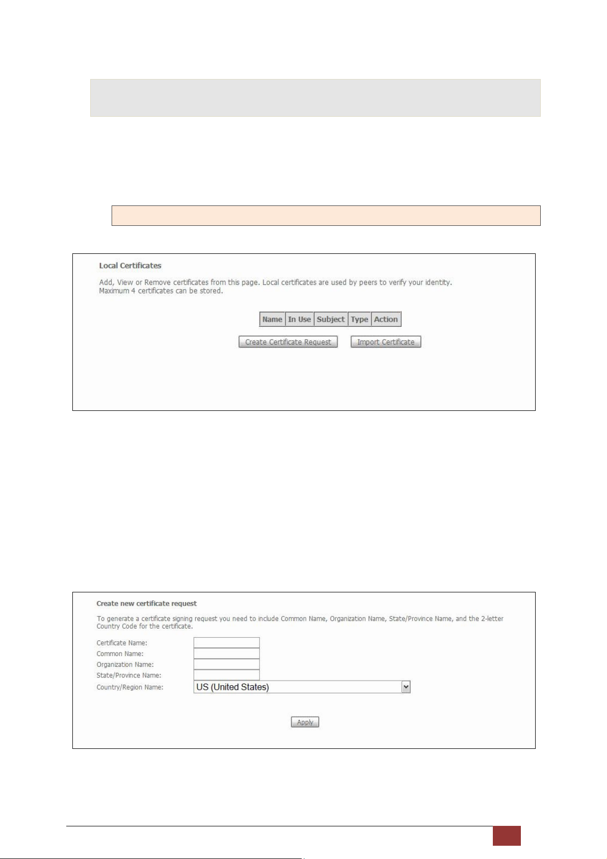
5.15.1 Local
CREATE CERTIFICATE REQUEST
Click Create Certificate Request to generate a certificate-signing request.
The certificate-signing request can be submitted to the vendor/ISP/ITSP to apply for a certificate. Some
information must be included in the certificate-signing request. Your vendor/ISP/ITSP will ask you to provide
the information they require and to provide the information in the format they regulate. Enter the required
information and click Apply to generate a private key and a certificate-signing request.
The following table is provided for your reference.
Proscend 130 ADSL2+/VDSL2 WLAN Router User Manual V0.02 70
Page 72
Field Description
Certificate Name A user-defined name for the certificate.
Common Name Usually, the fully qualified domain name for the machine.
Organization Name The exact legal name of your organization.
Do not abbreviate.
State/Province Name The state or province where your organization is located. It cannot
be abbreviated.
Country/Region Name The two-letter ISO abbreviation for your country.
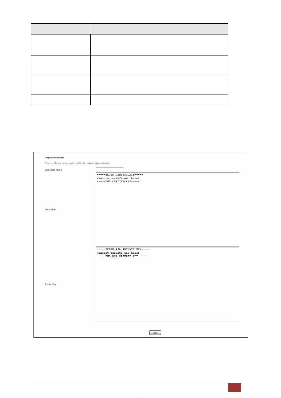
IMPORT CERTIFICATE
Click Import Certificate to paste the certificate content and the private key provided by your vendor/ISP/ITSP
into the corresponding boxes shown below.
Enter a certificate name and click Apply to import the local certificate.
Proscend 130 ADSL2+/VDSL2 WLAN Router User Manual V0.02 71
Page 73
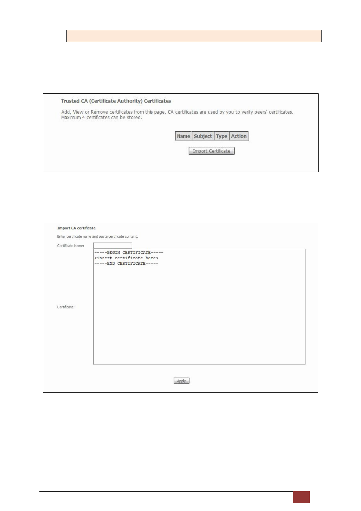
5.15.2 Trusted CA
CA is an abbreviation for Certificate Authority, which is a part of the X.509 system. It is itself a certificate,
attached with the owner information of this certificate authority; but its purpose is not encryption/decryption.
Its purpose is to sign and issue certificates, in order to prove that these certificates are valid.
Click Import Certificate to paste the certificate content of your trusted CA. The CA certificate content will be
provided by your vendor/ISP/ITSP and is used to authenticate the Auto-Configuration Server (ACS) that the CPE
will connect to.
Enter a certificate name and click Apply to import the CA certificate.
Proscend 130 ADSL2+/VDSL2 WLAN Router User Manual V0.02 72
Page 74
5.16 Power Management
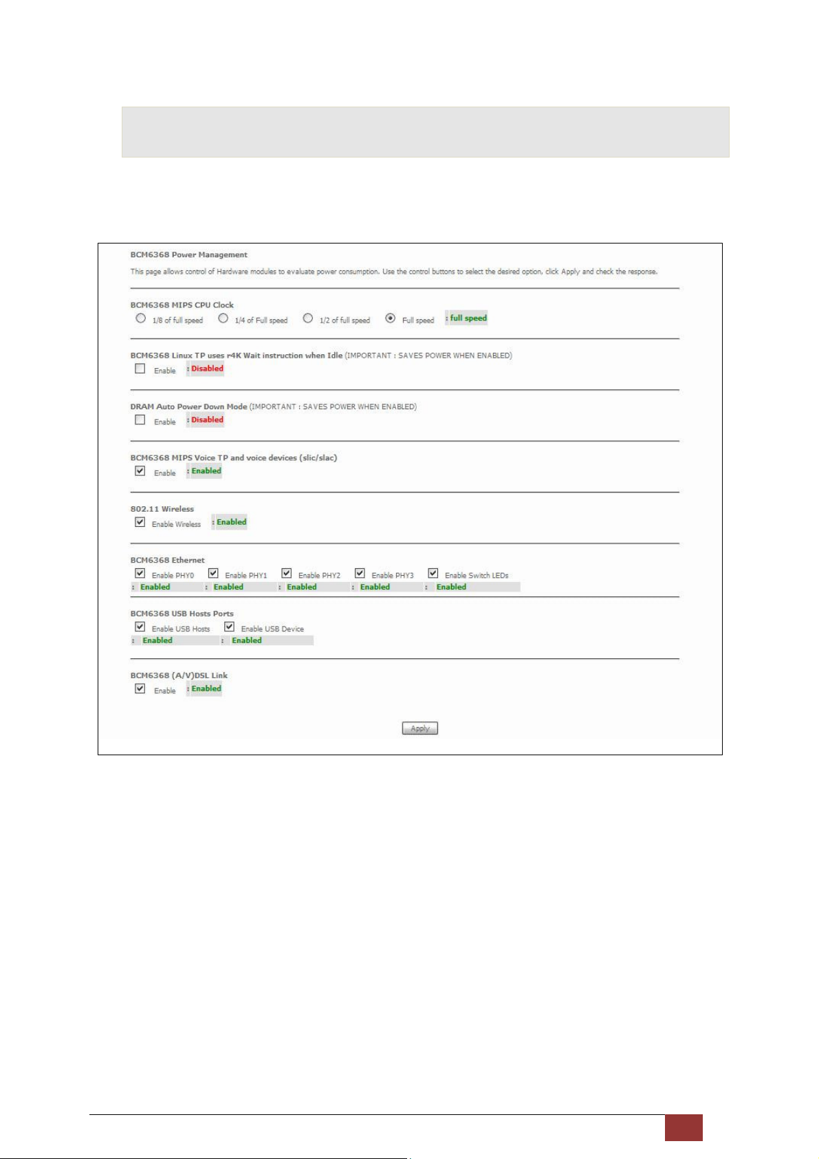
This screen allows for control of hardware modules to evaluate power consumption. Use the buttons to select
the desired option, click Apply and check the response.
Proscend 130 ADSL2+/VDSL2 WLAN Router User Manual V0.02 73
Page 75
6 Wireless
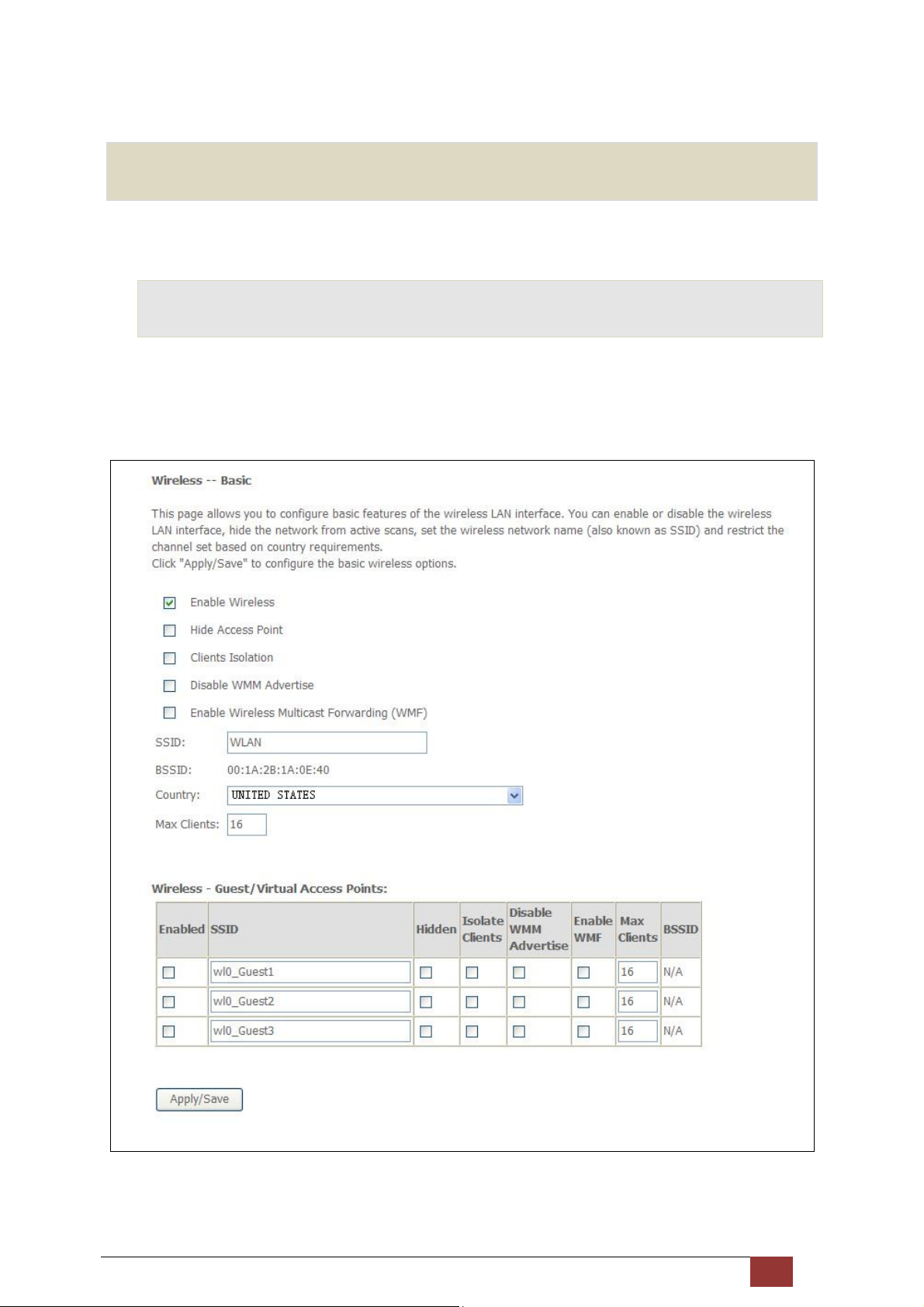
The Wireless menu provides access to the wireless options discussed below.
6.1 Basic
The Basic option allows you to configure basic features of the wireless LAN interface. Among other things, you
can enable or disable the wireless LAN interface, hide the network from active scans, set the wireless network
name (also known as SSID, Service Set Identifier) and restrict the channel set based on country requirements.
Click Save/Apply to apply the selected wireless options.
Consult the table below for descriptions of these options.
Proscend 130 ADSL2+/VDSL2 WLAN Router User Manual V0.02 74
Page 76

Option Description
Enable Wireless A checkbox that enables or disables the wireless LAN interface. When
selected, a set of basic wireless options will appear.
Hide Access Point Select Hide Access Point to protect the access point from detection by wireless
active scans. To check AP status in Windows XP, open Network Connections
from the start Menu and select View Available Network Connections. If the
access point is hidden, it will not be listed there. To connect a client to a hidden
access point, the station must add the access point manually to its wireless
configuration.
Clients Isolation When enabled, it prevents client PCs from seeing one another in My Network
Places or Network Neighborhood. Also, prevents one wireless client
communicating with another wireless client.
Disable WMM Advertise
Stops the router from ‘advertising’ its Wireless Multimedia (WMM)
functionality, which provides basic quality of service for time-sensitive
applications (e.g. VoIP, Video).
Enable Wireless Multicast
Not supported.
Forwarding
SSID
[1-32 characters]
Sets the wireless network name. SSID stands for Service Set Identifier. All
stations must be configured with the correct SSID to access the WLAN. If the
SSID does not match, that user will not be granted access.
BSSID The BSSID is a 48-bit identity used to identify a particular BSS (Basic Service Set)
within an area. In Infrastructure BSS networks, the BSSID is the MAC (Media
Access Control) address of the AP (Access Point); and in Independent BSS or ad
hoc networks, the BSSID is generated randomly.
Country A drop-down menu that permits worldwide and specific national settings.
Local regulations limit channel range:
US= worldwide, Japan=1-14, Jordan= 10-13, Israel= 1-13
Max Clients The maximum number of clients that can access the router.
Wireless - Guest / Virtual
Access Points
This router supports multiple SSIDs called Guest SSIDs or Virtual Access Points.
To enable one or more Guest SSIDs select the checkboxes in the Enabled
column. To hide a Guest SSID select its checkbox in the Hidden column.
Do the same for Isolate Clients and Disable WMM Advertise. For a description
of these two functions, see the previous entries for “Clients Isolation” and
“Disable WMM Advertise”. Similarly, for Enable WMF, Max Clients and BSSID,
consult the matching entries in this table.
NOTE: Remote wireless hosts cannot scan Guest SSIDs.
Proscend 130 ADSL2+/VDSL2 WLAN Router User Manual V0.02 75
Page 77
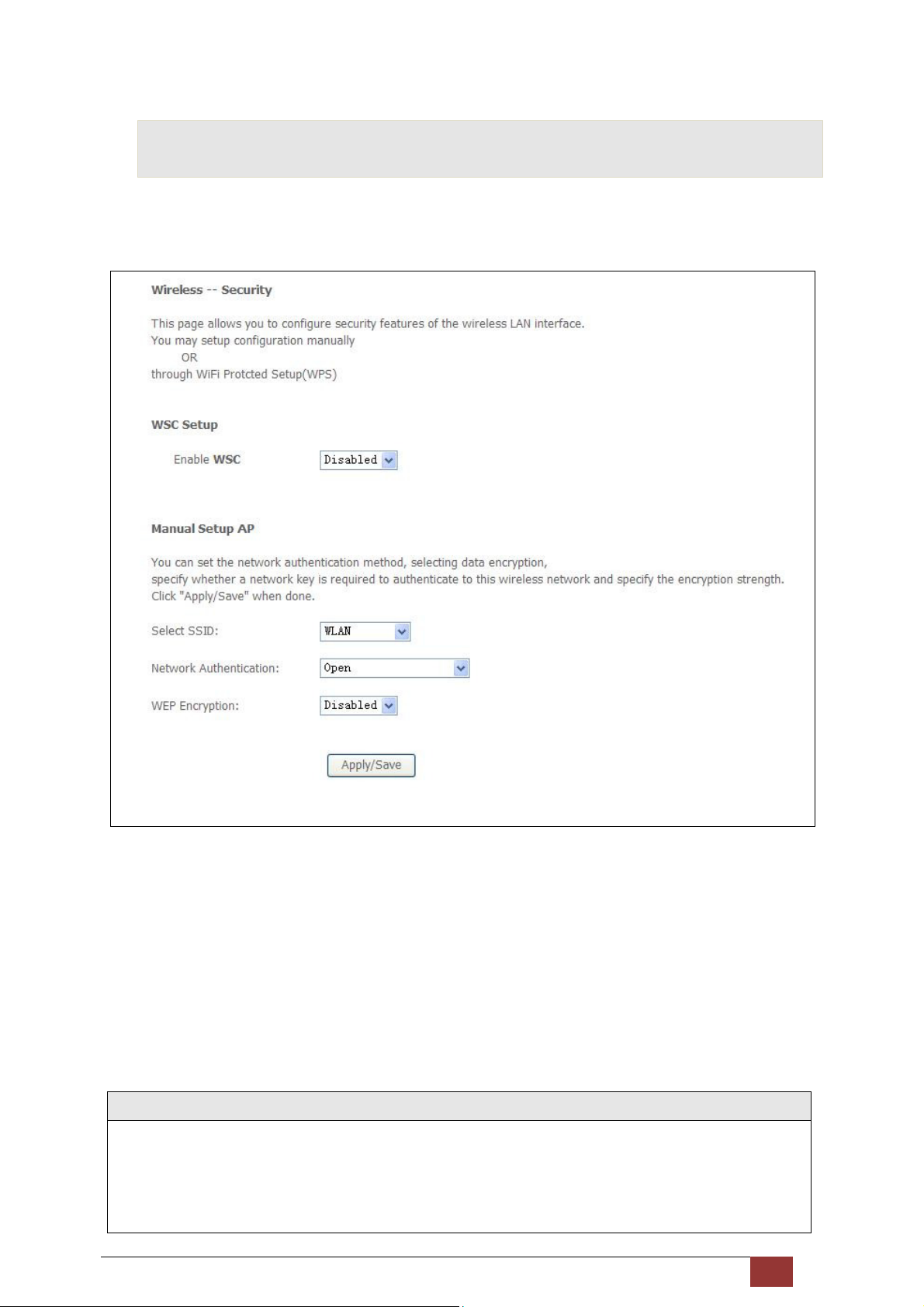
6.2 Security
The following screen appears when Wireless Security is selected. The options shown here allow you to
configure security features of the wireless LAN interface.
Click Save/Apply to implement new configuration settings.
WIRELESS SECURITY
Wireless security settings can be configured according to Wi-Fi Protected Setup (WPS) or Manual Setup. The
WPS method configures security settings automatically while the Manual Setup method requires that the user
configure these settings using the Web User Interface (see the table below).
Select SSID
Select the wireless network name from the drop-down box. SSID stands for Service Set Identifier. All stations
must be configured with the correct SSID to access the WLAN. If the SSID does not match, that client will not
be granted access.
Proscend 130 ADSL2+/VDSL2 WLAN Router User Manual V0.02 76
Page 78
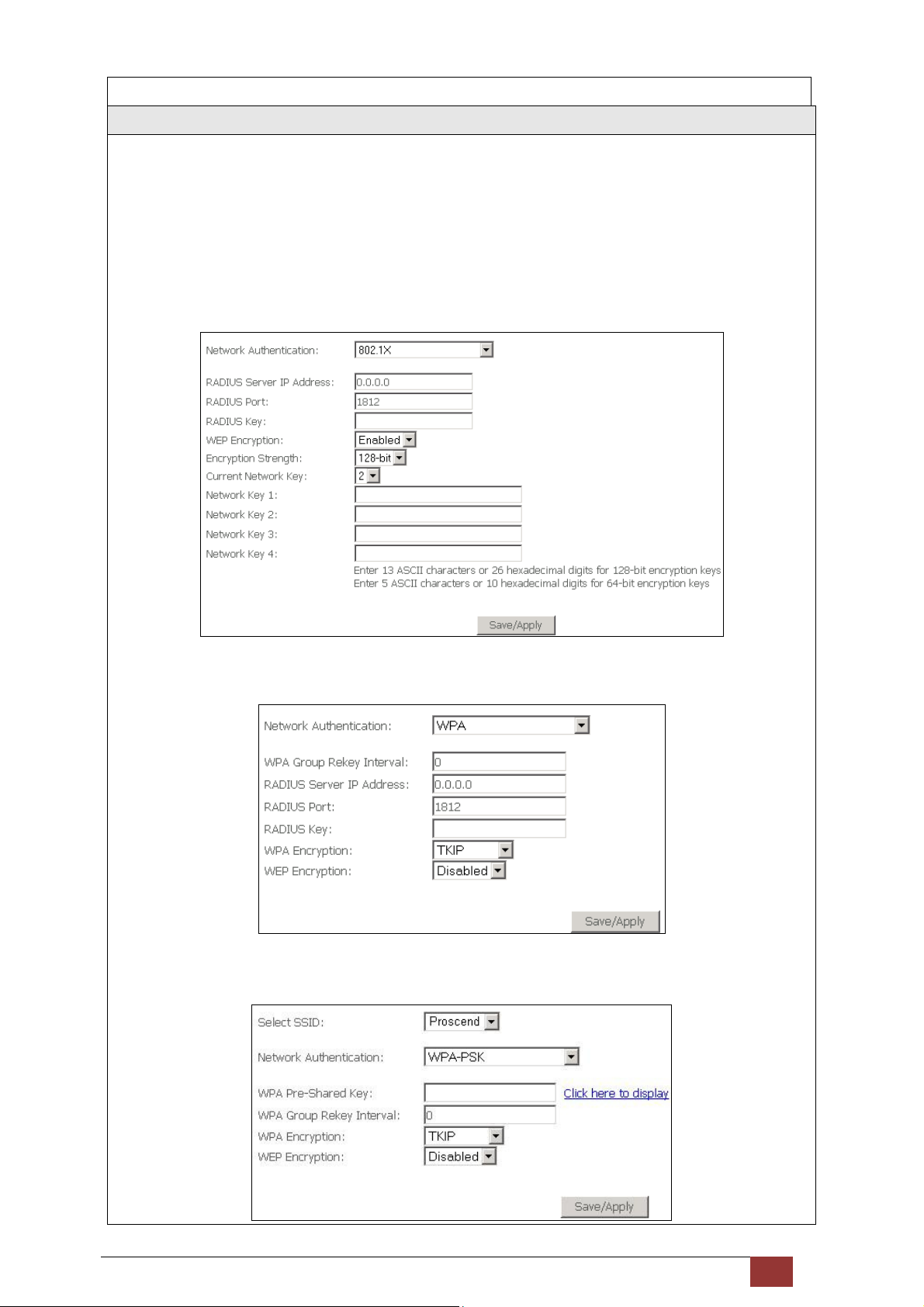
Network Authentication
This option specifies whether a network key is used for authentication to the wireless network. If network
authentication is set to Open, then no authentication is provided. Despite this, the identity of the client is still
verified.
Each authentication type has its own settings. For example, selecting 802.1X authentication will reveal the
RADIUS Server IP address, Port and Key fields. WEP Encryption will also be enabled as shown below.
The settings for WPA authentication are shown below.
The settings for WPA-PSK authentication are shown next.
Proscend 130 ADSL2+/VDSL2 WLAN Router User Manual V0.02 77
Page 79
WEP Encryption
This option specifies whether data sent over the network is encrypted. The same network key is used for data
encryption and network authentication. Four network keys can be defined although only one can be used at
any one time. Use the Current Network Key list box to select the appropriate network key.
Security options include authentication and encryption services based on the wired equivalent privacy (WEP)
algorithm. WEP is a set of security services used to protect 802.11 networks from unauthorized access, such as
eavesdropping; in this case, the capture of wireless network traffic. When data encryption is enabled, secret
shared encryption keys are generated and used by the source station and the destination station to alter frame
bits, thus avoiding disclosure to eavesdroppers.
Under shared key authentication, each wireless station is assumed to have received a secret shared key over a
secure channel that is independent from the 802.11 wireless network communications channel.
Encryption Strength
This drop-down list box will display when WEP Encryption is enabled. The key strength is proportional to the
number of binary bits comprising the key. This means that keys with a greater number of bits have a greater
degree of security and are considerably more difficult to crack. Encryption strength can be set to either 64-bit
or 128-bit. A 64-bit key is equivalent to 5 ASCII characters or 10 hexadecimal numbers. A 128-bit key contains
13 ASCII characters or 26 hexadecimal numbers. Each key contains a 24-bit header (an initiation vector) which
enables parallel decoding of multiple streams of encrypted data.
6.2.1 WPS
Wi-Fi Protected Setup (WPS) is an industry standard that simplifies wireless security setup for certified network
devices. Every WPS certified device has both a PIN number and a push button, located on the device or
accessed through device software. The Proscend 130 has both a WPS button on the device and a virtual button
accessible from the web user interface (WUI).
Devices with the WPS logo (shown here) support WPS. If the
WPS logo is not present on your device it still may support WPS,
in this case, check the device documentation for the phrase
“Wi-Fi Protected Setup”.
NOTE: WPS is only available in Open, WPA-PSK, WPA2-PSK and Mixed WPA2/WPA-PSK network
authentication modes. Other authentication modes do not use WPS so they must be configured
manually.
Proscend 130 ADSL2+/VDSL2 WLAN Router User Manual V0.02 78
Page 80
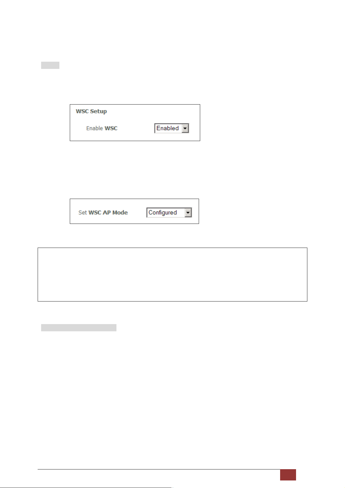
To configure security settings with WPS, follow the procedures below. You must choose either the Push-Button
or PIN configuration method for Steps 6 and 7.
I. Setup
Step 1: Enable WPS by selecting Enabled from the drop down list box shown.
Step 2: Set the WSC AP Mode. Configured is used when the Proscend 130 will assign security settings to
clients. Unconfigured is used when an external client assigns security settings to the Proscend 130.
NOTES: Your client may or may not have the ability to provide security settings to the Proscend 130. If it
does not, then you must set the WSC AP mode to Configured. Consult the device documentation
to check its capabilities.
In addition, using Windows Vista, you can add an external registrar using the StartAddER button
(9.3has detailed instructions).
II. NETWORK AUTHENTICATION
Step 3: Select Open, WPA-PSK, WPA2-PSK, or Mixed WPA2/WPA-PSK network authentication mode from
the Manual Setup AP section of the Wireless Security screen. The example below shows WPA2-PSK
mode.
Proscend 130 ADSL2+/VDSL2 WLAN Router User Manual V0.02 79
Page 81
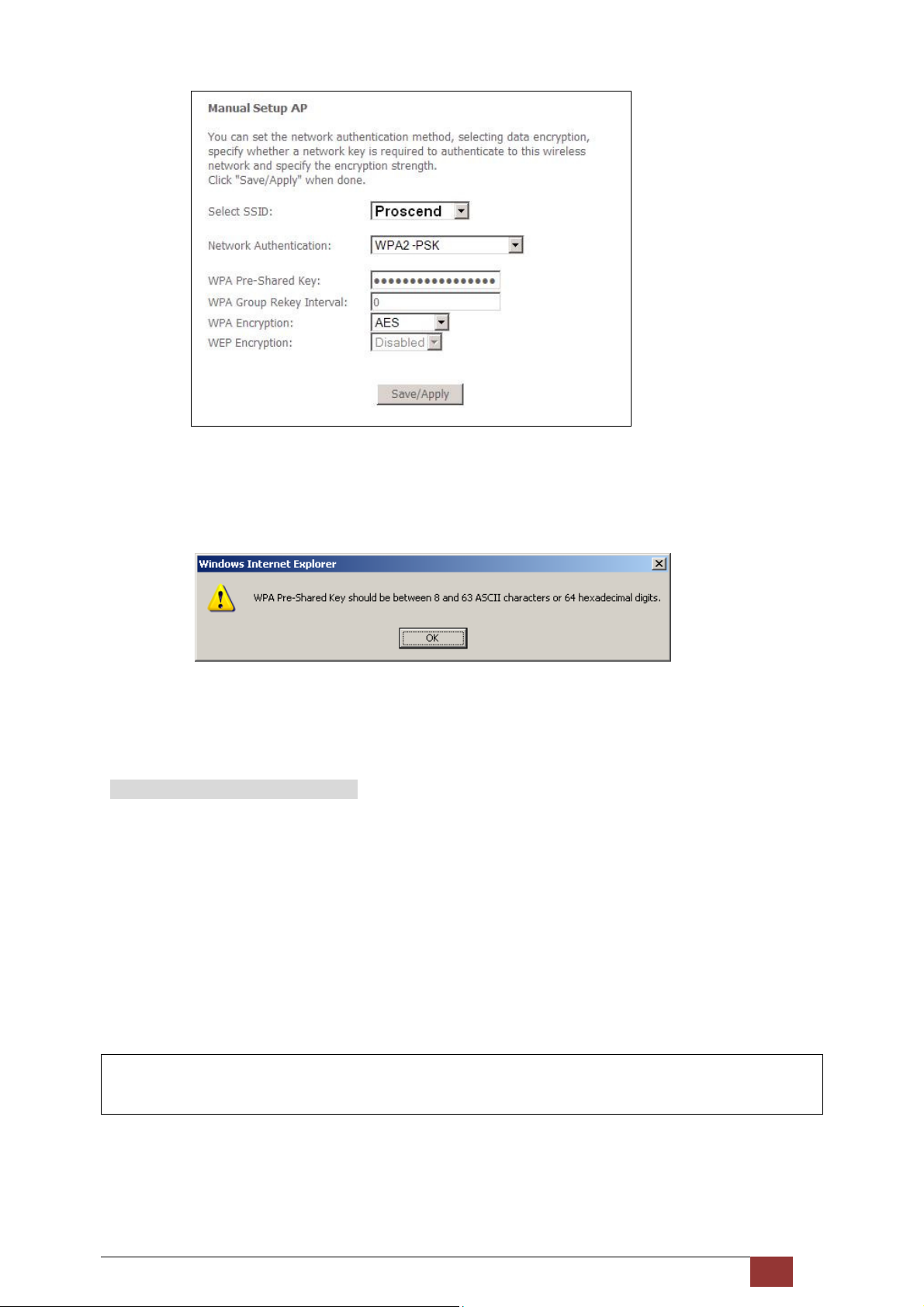
Step 4: For the Pre-Shared Key (PSK) modes, enter a WPA Pre-Shared Key. You will see the following
dialog box if the Key is too short or too long.
Step 5: Click the Save/Apply button at the bottom of the screen.
IIIa. PUSH-BUTTON CONFIGURATION
The WPS push-button configuration provides a semi-automated configuration method. The WPS button on
the rear panel of the router can be used for this purpose or the Web User Interface (WUI) can be used
exclusively.
The WPS push-button configuration is described in the procedure below. It is assumed that the Wireless
function is Enabled and that the router is configured as the Wireless Access Point (AP) of your WLAN. In
addition, the wireless client must also be configured correctly and turned on, with WPS function enabled.
NOTE: The wireless AP on the router searches for 2 minutes. If the router stops searching before you
complete Step 7, return to Step 6.
Step 6: First method: WPS button
Press the WPS button on the rear panel of the router. The WPS LED will blink to show that the
router has begun searching for the client.
Proscend 130 ADSL2+/VDSL2 WLAN Router User Manual V0.02 80
Page 82
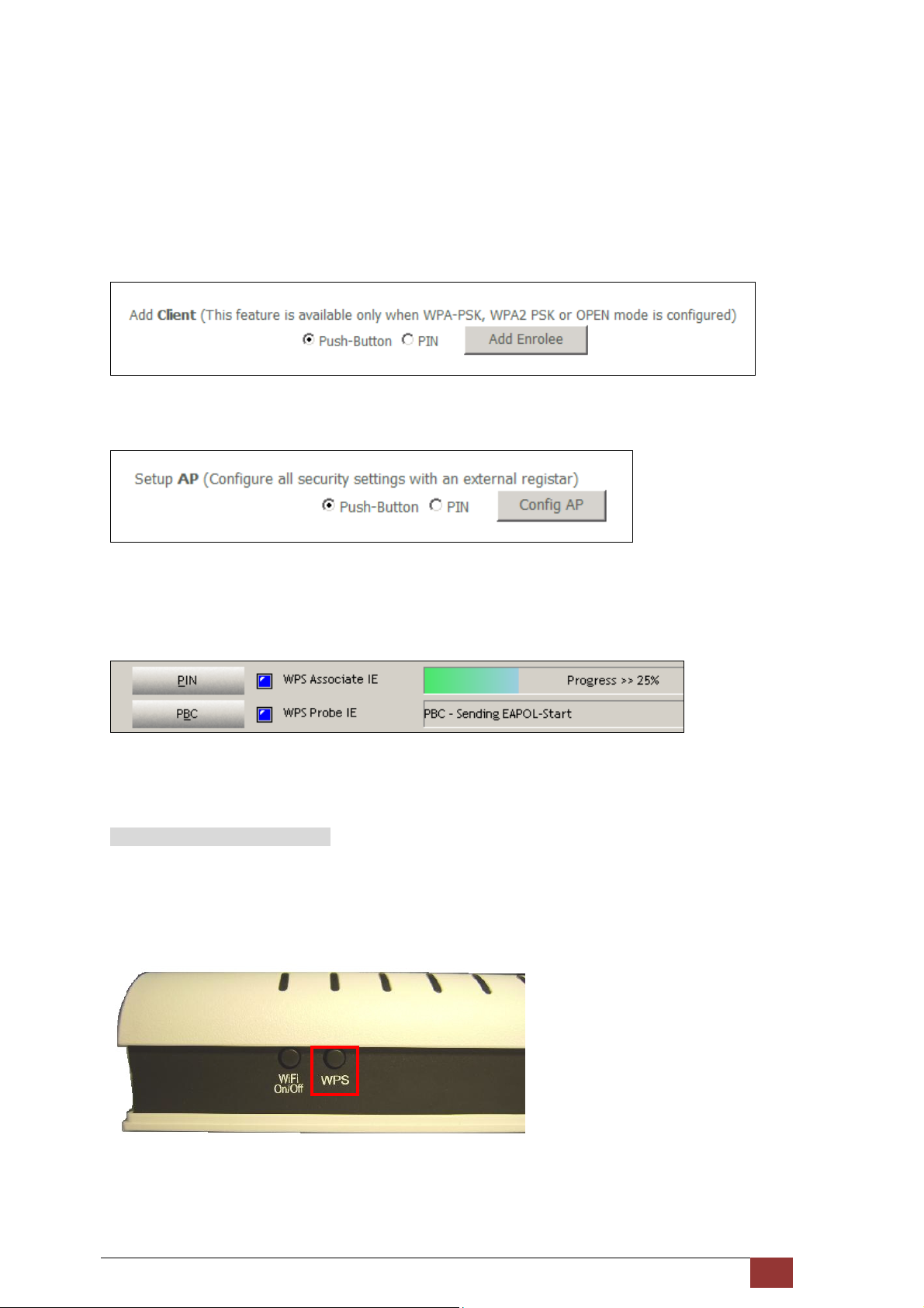
Second method: WUI virtual button
Select the Push-Button radio button in the WSC Setup section of the Wireless Security screen, as
shown in A or B below, and then click the appropriate button based on the WSC AP mode selected
in step 2.
A - For Configured mode, click the Add Enrollee button.
B - For Unconfigured mode, click the Config AP button.
Step 7: Go to your WPS wireless client and activate the push-button function.
A typical WPS client screenshot is shown below as an example.
Now go to Step 8 (part IV. Check Connection) to check the WPS connection.
IIIb. WPS – PIN CONFIGURATION
Proscend 130 ADSL2+/VDSL2 WLAN Router User Manual V0.02 81
Page 83
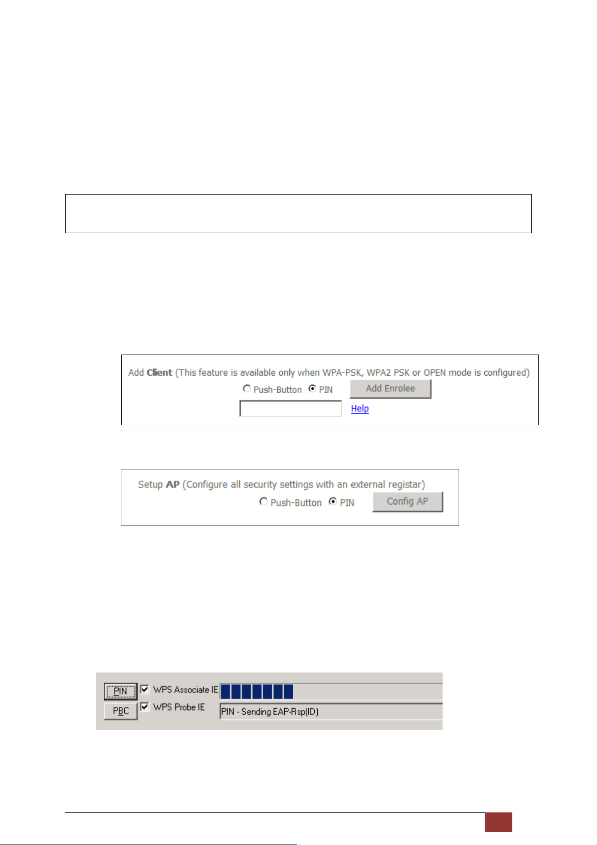
Using this method, security settings are configured with a personal identification number (PIN). The PIN can be
found on the device itself or within the software. The PIN may be generated randomly in the latter case. To
obtain a PIN number for your client, check the device documentation for specific instructions.
The WPS PIN configuration is described in the procedure below. It is assumed that the Wireless function is
Enabled and that the router is configured as the Wireless Access Point (AP) of your wireless LAN. In addition,
the wireless client must also be configured correctly and turned on, with WPS function enabled.
NOTE: Unlike the push-button method, the pin method has no set time limit. This means that the router
will continue searching until it finds a client.
Step 6: Select the PIN radio button in the WSC Setup section of the W ireless Security screen, as shown in
A or B below, and then click the appropriate button based on the WSC AP mode selected in step 2.
A - For Configured mode, enter the client PIN in the box provided and then click the Add Enrollee
button (see below).
B - For Unconfigured mode, click the Config AP button.
Step 7: Activate the PIN function on the wireless client.
For Configured mode, the client must be configured as an Enrollee.
For Unconfigured mode, the client must be configured as the Registrar.
This is different from the External Registrar function provided in Windows Vista.
The figure below provides an example of a WPS client PIN function in-progress.
Now go to Step 8 (Check Connection) to check the WPS connection.
Proscend 130 ADSL2+/VDSL2 WLAN Router User Manual V0.02 82
Page 84
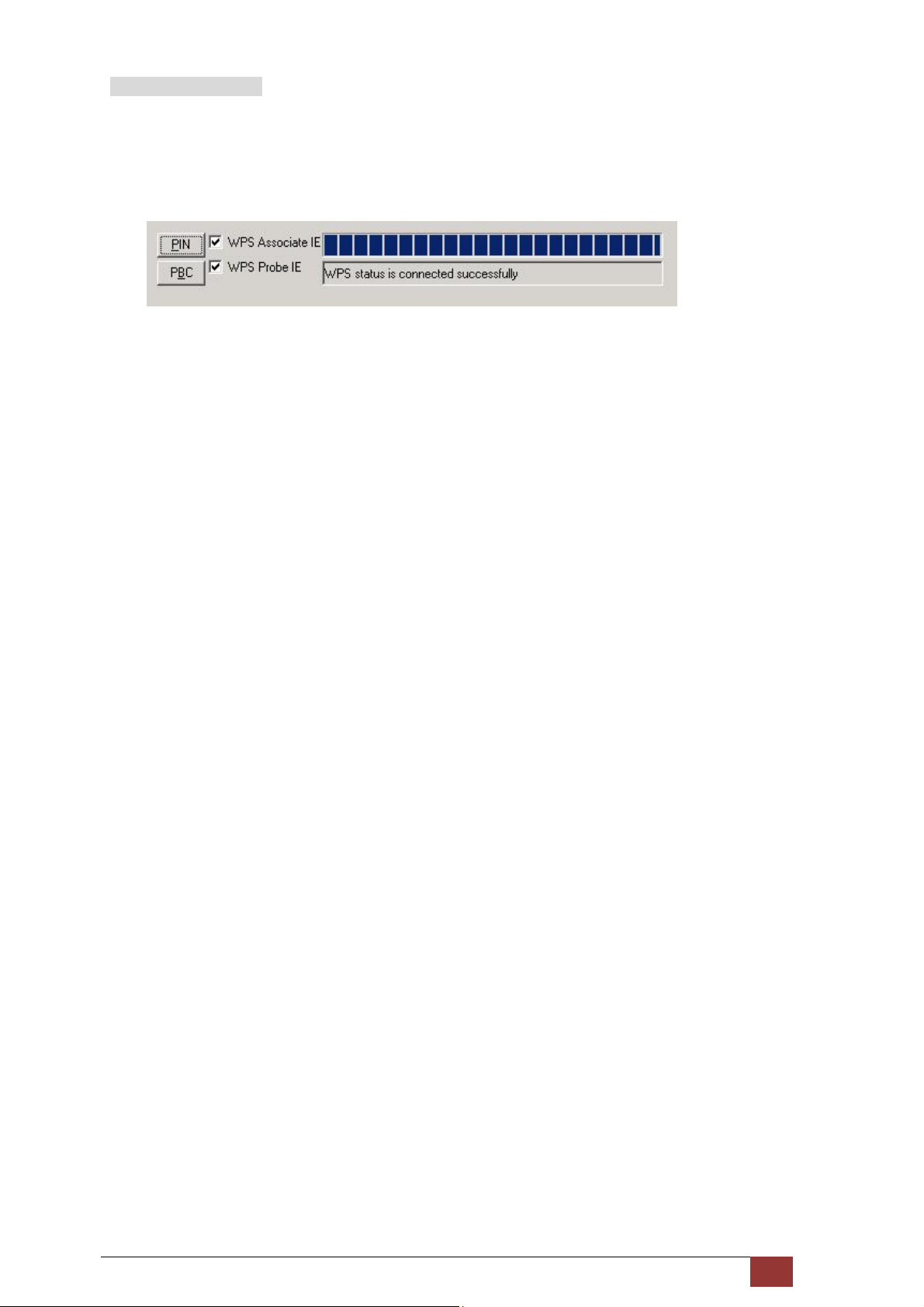
IV. CHECK CONNECTION
Step 8: If the WPS setup method was successful, you will be able access the wireless AP from the client.
The client software should show the status. The example below shows that the connection
established successfully.
You can also double-click the Wireless Network Connection icon from the Network Connections
window (or the system tray) to confirm the status of the new connection.
Proscend 130 ADSL2+/VDSL2 WLAN Router User Manual V0.02 83
Page 85
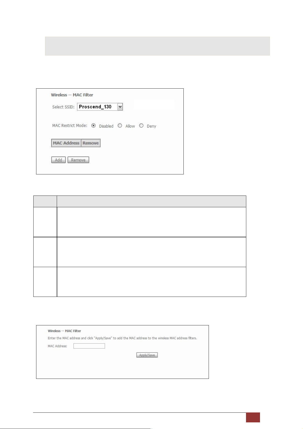
6.3 MAC Filter
This option allows access to the router to be restricted based upon MAC addresses. To add a MAC Address
filter, click the Add button shown below. To delete a filter, select it from the MAC Address table below and click
the Remove button.
Option Description
Select
SSID
MAC
Restrict
Mode
MAC
Address
After clicking the Add button, the following screen appears.
Enter the MAC address in the box provided and click Save/Apply.
Select the wireless network name from the drop-down box. SSID stands for Service Set
Identifier. All stations must be configured with the correct SSID to access the WLAN. If
the SSID does not match, that user will not be granted access.
Disabled: MAC filtering is disabled.
Allow: Permits access for the specified MAC addresses.
Deny: Rejects access for the specified MAC addresses.
Lists the MAC addresses subject to the MAC Restrict Mode. A maximum of 60 MAC
addresses can be added. Every network device has a unique 48-bit MAC address. This is
usually shown as xx.xx.xx.xx.xx.xx, where xx are hexadecimal numbers.
Proscend 130 ADSL2+/VDSL2 WLAN Router User Manual V0.02 84
Page 86
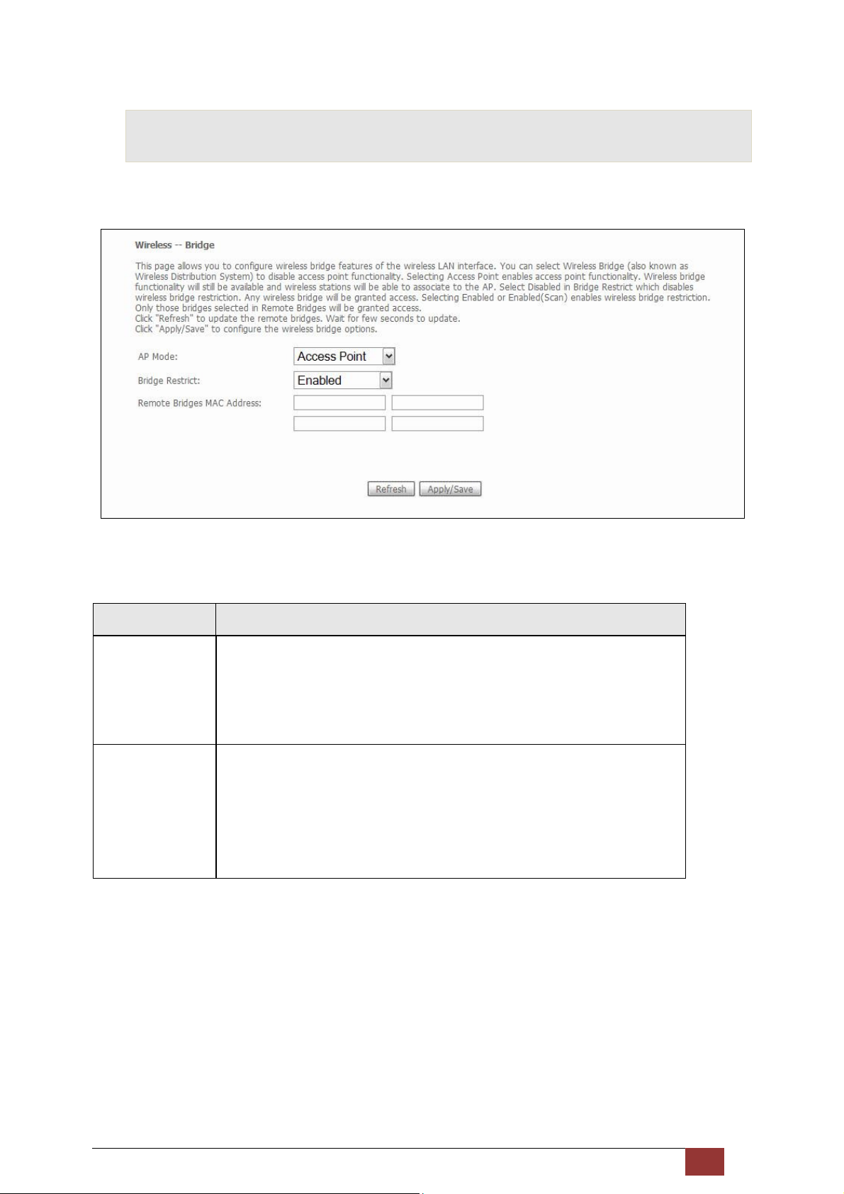
6.4 Wireless Bridge
This screen allows for the configuration of wireless bridge features of the WLAN interface. See the table
beneath for detailed explanations of the various options.
Click Save/Apply to implement new configuration settings.
Feature Description
AP Mode Selecting Wireless Bridge (aka Wireless Distribution System) disables Access
Point (AP) functionality, while selecting Access Point enables AP functionality.
In Access Point mode, wireless bridge functionality will still be available and
wireless stations will be able to associate to the AP.
Bridge Restrict Selecting Disabled disables wireless bridge restriction, which means that any
wireless bridge will be granted access. Selecting Enabled or Enabled (Scan)
enables wireless bridge restriction. Only those bridges selected in the Remote
Bridges list will be granted access. Click Refresh to update the station list when
Bridge Restrict is enabled.
Proscend 130 ADSL2+/VDSL2 WLAN Router User Manual V0.02 85
Page 87
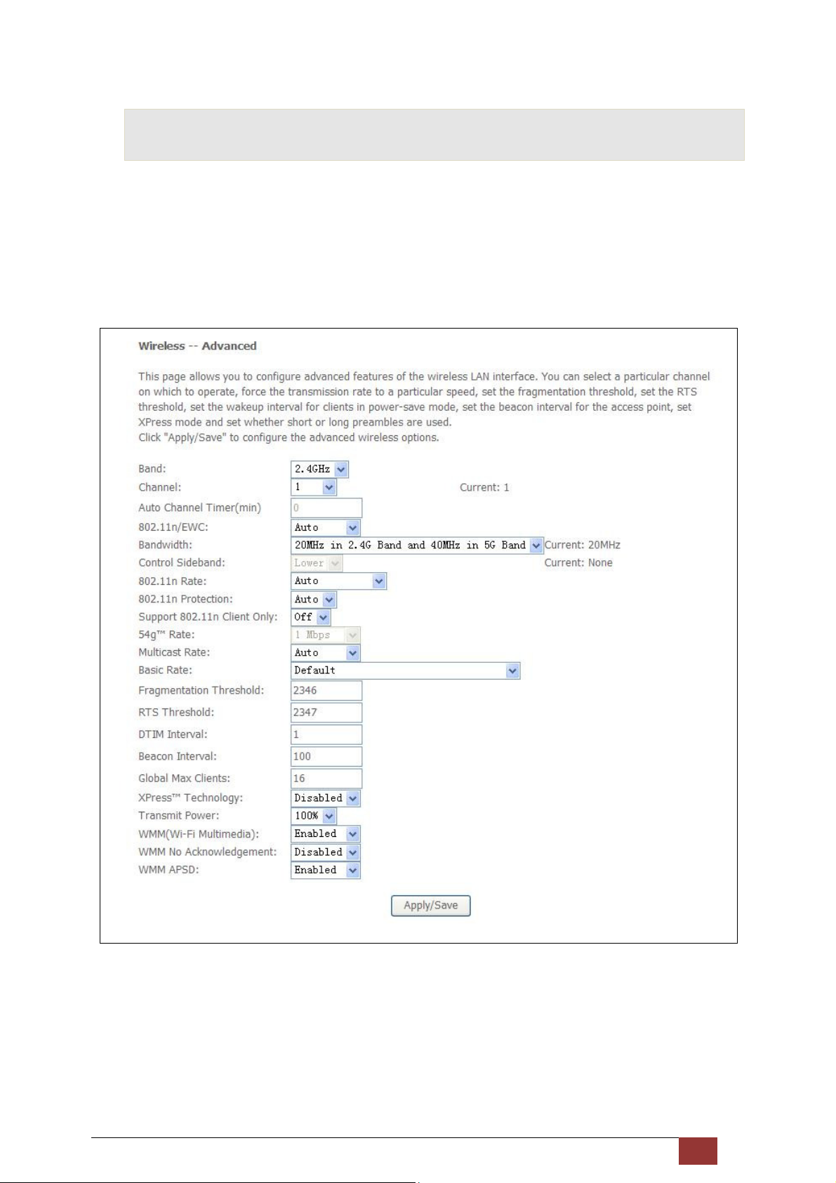
6.5 Advanced
The Advanced screen allows you to configure advanced features of the wireless LAN interface. You can select a
particular channel on which to operate, force the transmission rate to a particular speed, set the fragmentation
threshold, set the RTS threshold, set the wakeup interval for clients in power-save mode, set the beacon
interval for the access point, set XPress mode and set whether short or long preambles are used.
Click Save/Apply to set new advanced wireless options.
Proscend 130 ADSL2+/VDSL2 WLAN Router User Manual V0.02 86
Page 88
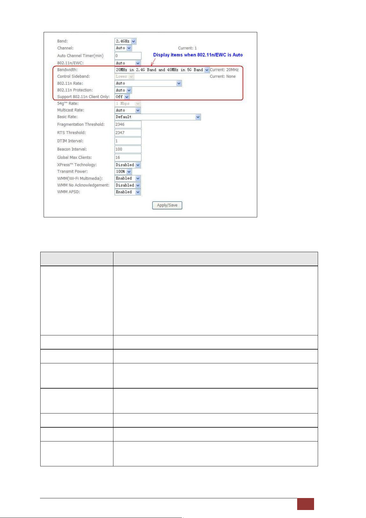
Field Description
Band Set to 2.4 GHz for compatibility with IEEE 802.11x standards. The new
amendment allows IEEE 802.11n units to fall back to slower speeds so that
legacy IEEE 802.11x devices can coexist in the same network. IEEE 802.11g
creates data-rate parity at 2.4 GHz with the IEEE 802.11a standard, which has a
54 Mbps rate at 5 GHz. (IEEE 802.11a has other differences compared to IEEE
802.11b or g, such as offering more channels.)
Channel Drop-down menu that allows selection of a specific channel.
Auto Channel Timer (min) Auto channel scan timer in minutes (0 to disable)
802.11n/EWC An equipment interoperability standard setting based on IEEE 802.11n Draft
2.0 and Enhanced Wireless Consortium (EWC)
Bandwidth Select 20GHz or 40GHz bandwidth. 40GHz bandwidth uses two adjacent 20GHz
bands for increased data throughput.
Control Sideband Select Upper or Lower sideband when in 40GHz mode.
802.11n Rate Set the physical transmission rate (PHY).
802.11n Protection Turn Off for maximized throughput.
Turn On for greater security.
Proscend 130 ADSL2+/VDSL2 WLAN Router User Manual V0.02 87
Page 89

Field Description
Support 802.11n Client
Only
Turn Off to allow 802.11b/g clients access to the router.
Turn On to prohibit 802.11b/g clients access to the router.
54g Rate Drop-down menu that specifies the following fixed rates: Default is AUTO.
Uses the 11 Mbps data rate when possible but drops to lower rates when
necessary.
The appropriate setting is dependent on signal strength.
Multicast Rate Setting for multicast packet transmit rate (1-54 Mbps)
Basic Rate Setting for basic transmission rate.
Fragmentation Threshold A threshold, specified in bytes, that determines whether packets will be
fragmented and at what size. On an 802.11 WLAN, packets that exceed the
fragmentation threshold are fragmented, i.e., split into, smaller units suitable
for the circuit size. Packets smaller than the specified fragmentation
threshold value are not fragmented. Enter a value between 256 and 2346. If
you experience a high packet error rate, try to slightly increase your
Fragmentation Threshold. The value should remain at its default setting of
2346. Setting the Fragmentation Threshold too low may result in poor
performance.
RTS Threshold Request to Send, when set in bytes, specifies the packet size beyond which the
WLAN Card invokes its RTS/CTS mechanism. Packets that exceed the
specified RTS threshold trigger the RTS/CTS mechanism. The NIC transmits
smaller packet without using RTS/CTS. The default setting of 2347 (maximum
length) disables RTS Threshold.
DTIM Interval Delivery Traffic Indication Message (DTIM) is also known as Beacon Rate. The
entry range is a value between 1 and 65535. A DTIM is a countdown variable
that informs clients of the next window for listening to broadcast and multicast
messages. When the AP has buffered broadcast or multicast messages for
associated clients, it sends the next DTIM with a DTIM Interval value. AP
Clients hear the beacons and awaken to receive the broadcast and multicast
messages. The default is 1.
Beacon Interval The amount of time between beacon transmissions in milliseconds. The
default is 100 ms and the acceptable range is 1 – 65535. The beacon
transmissions identify the presence of an access point. By default, network
devices passively scan all RF channels listening for beacons coming from access
points. Before a station enters power save mode, the station needs the
beacon interval to know when to wake up to receive the beacon (and learn
whether there are buffered frames at the access point).
Global Max Clients The maximum number of clients that can connect to the router.
Proscend 130 ADSL2+/VDSL2 WLAN Router User Manual V0.02 88
Page 90
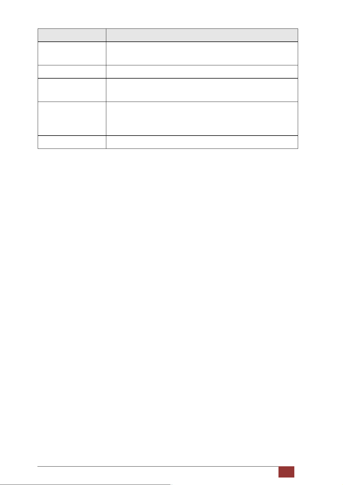
Field Description
TM
Xpress
Technology Xpress Technology is compliant with draft specifications of two planned
wireless industry standards.
Transmit Power Set the power output (by percentage) as desired.
WMM (Wi-Fi Multimedia) The technology maintains the priority of audio, video and voice applications in
a Wi-Fi network. It allows multimedia service get higher priority.
WMM No
Acknowledgement
Refers to the acknowledge policy used at the MAC level. Enabling no
Acknowledgement can result in more efficient throughput but higher error
rates in a noisy Radio Frequency (RF) environment.
WMM APSD This is Automatic Power Save Delivery. It saves power.
Proscend 130 ADSL2+/VDSL2 WLAN Router User Manual V0.02 89
Page 91
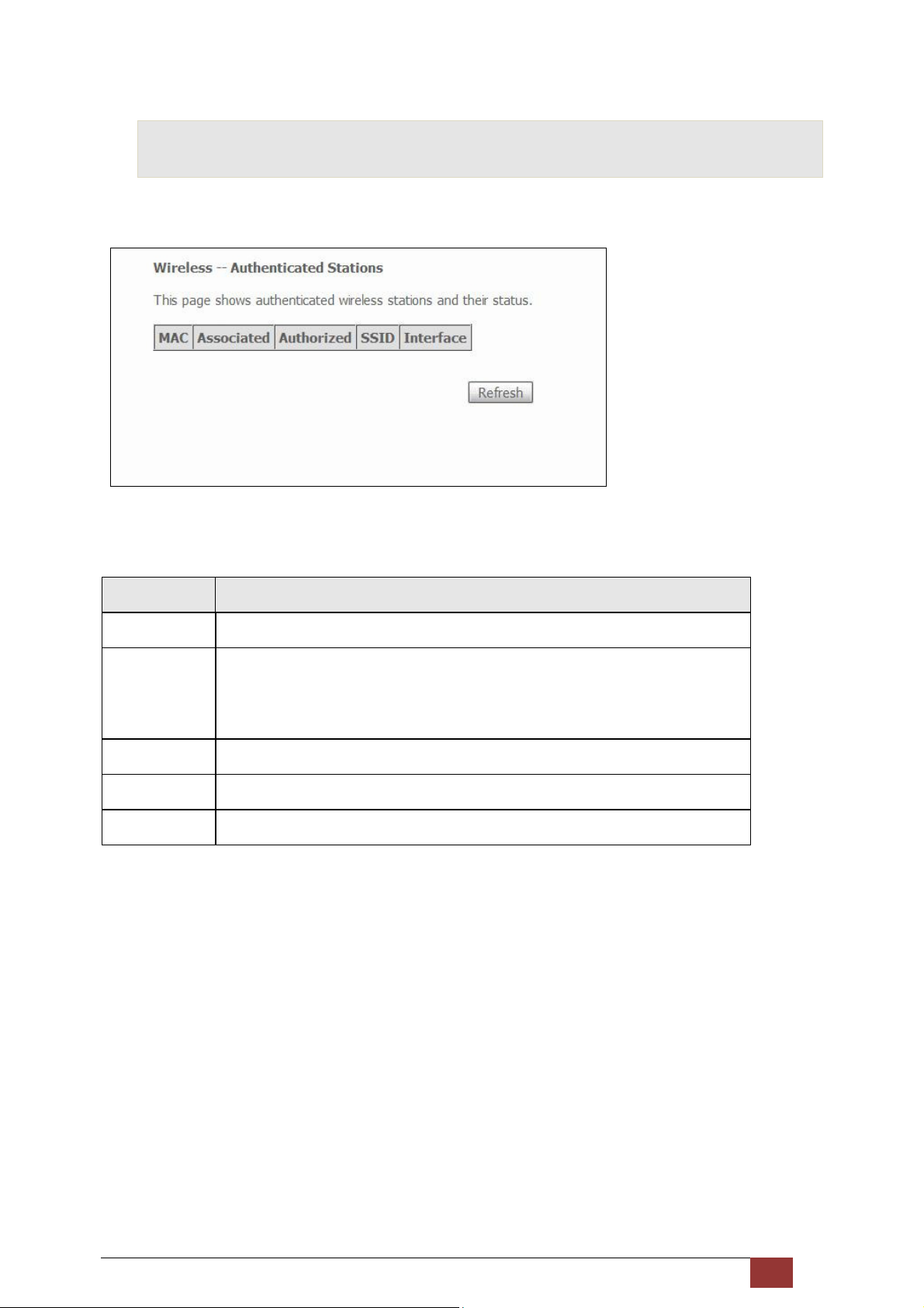
6.6 Station Info
This page shows authenticated wireless stations and their status. Click the Refresh button to update the list of
stations in the WLAN.
Consult the table below for descriptions of each column heading.
Heading Description
MAC Lists the MAC address of all the stations.
Associated Lists all the stations that are associated with the Access
Point, along with the amount of time since packets were transferred to and from
each station. If a station is idle for too long, it is removed from this list.
Authorized Lists those devices with authorized access.
SSID Lists which SSID of the modem that the stations connect to.
Interface Lists which interface of the modem that the stations connect to.
Proscend 130 ADSL2+/VDSL2 WLAN Router User Manual V0.02 90
Page 92
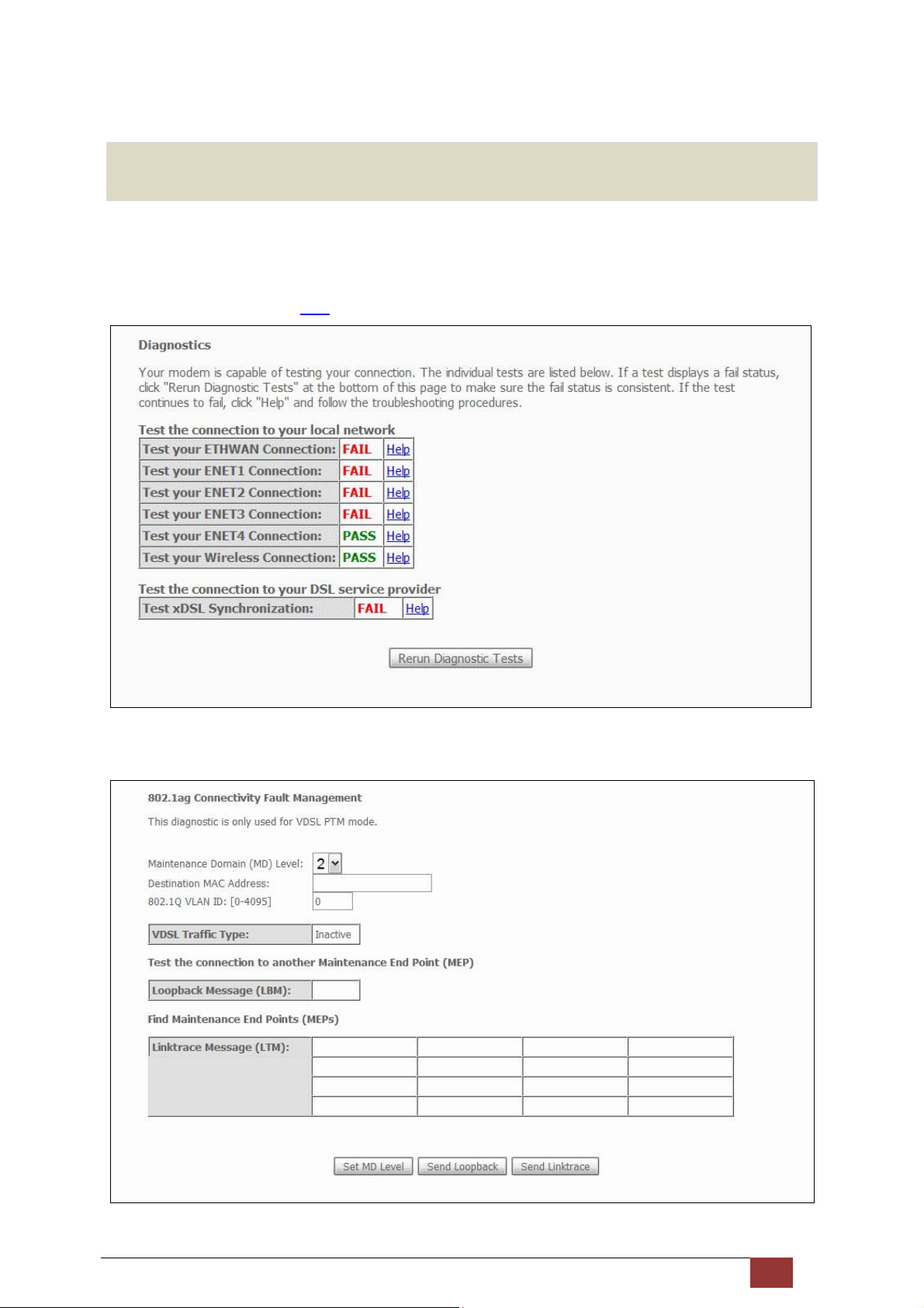
7 Diagnostics
The first Diagnostics screen is a dashboard that shows overall connection status.
If a test displays a fail status, click the button to retest and confirm the error.
If a test continues to fail, click Help and follow the troubleshooting procedures.
The second Diagnostics screen (Fault Management) is used for VDSL diagnostics.
Proscend 130 ADSL2+/VDSL2 WLAN Router User Manual V0.02 91
Page 93
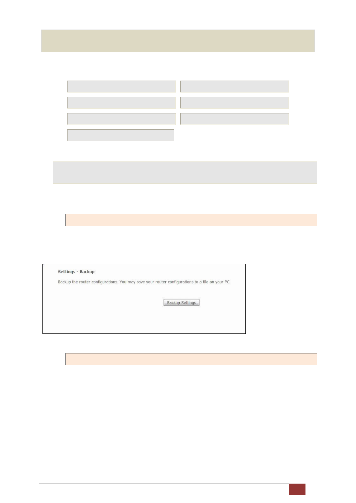
8 Management
The Management menu has the following maintenance functions and processes:
8.1 Settings 8.2 System Log
8.3 TR-069 Client 8.4 Internet Time
8.5 Access Control 8.6 Update Software
8.7 Reboot
8.1 Settings
This includes Backup Settings, Update Settings and Restore Default screens.
8.1.1 Backup Settings
To save the current configuration to a file on your PC, click Backup Settings. You will be prompted for backup
file location. This file can later be used to recover settings on the Update Settings screen, as described below.
8.1.2 Update Settings
This option recovers configuration files previously saved using Backup Settings. Enter the file name (including
folder path) in the Settings File Name box, or press Browse… to search for the file, then click Update Settings
to recover settings.
Proscend 130 ADSL2+/VDSL2 WLAN Router User Manual V0.02 92
Page 94
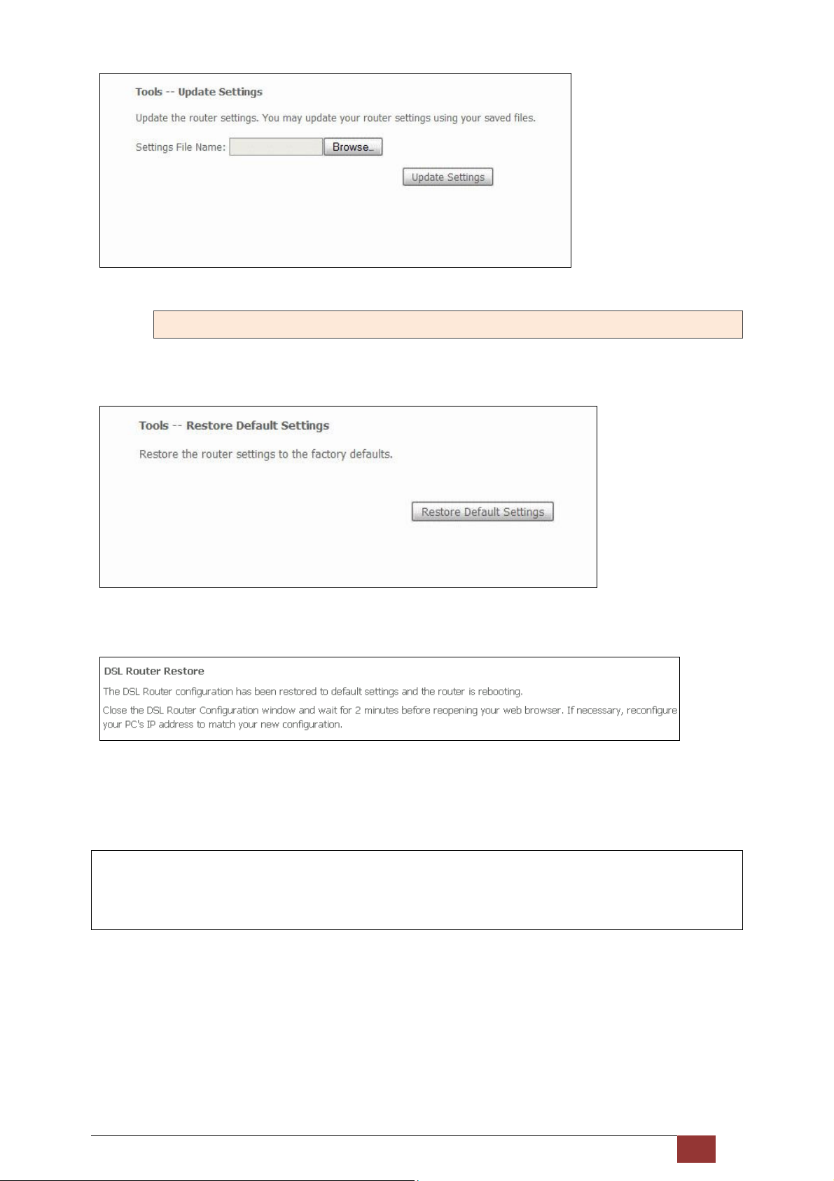
8.1.3 Restore Default
Click Restore Default Settings to restore factory default settings.
After Restore Default Settings is clicked, the following screen appears.
Close the browser and wait for 2 minutes before reopening it. It may also be necessary, to reconfigure your PC
IP configuration to match any new settings.
NOTE: This entry has the same effect as the Reset button. The Proscend 130 board hardware and the
boot loader support the reset to default. If the Reset button is continuously pressed for more than
5 seconds, the boot loader will erase the configuration data saved in flash memory.
Proscend 130 ADSL2+/VDSL2 WLAN Router User Manual V0.02 93
Page 95
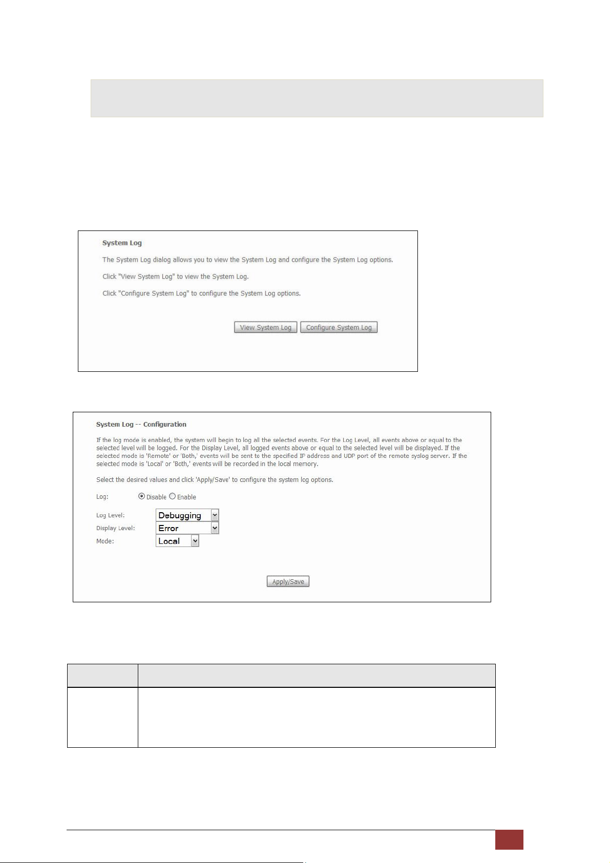
8.2 System Log
This function allows a system log to be kept and viewed upon request.
Follow the steps below to configure, enable, and view the system log.
STEP 1: Click Configure System Log, as shown below.
STEP 2: Select desired options and click Apply/Save.
Consult the table below for detailed descriptions of each system log option.
Option Description
Log Indicates whether the system is currently recording events. The user can enable
or disable event logging. By default, it is disabled. To enable it, select the
Enable radio button and then click Apply/Save.
Proscend 130 ADSL2+/VDSL2 WLAN Router User Manual V0.02 94
Page 96
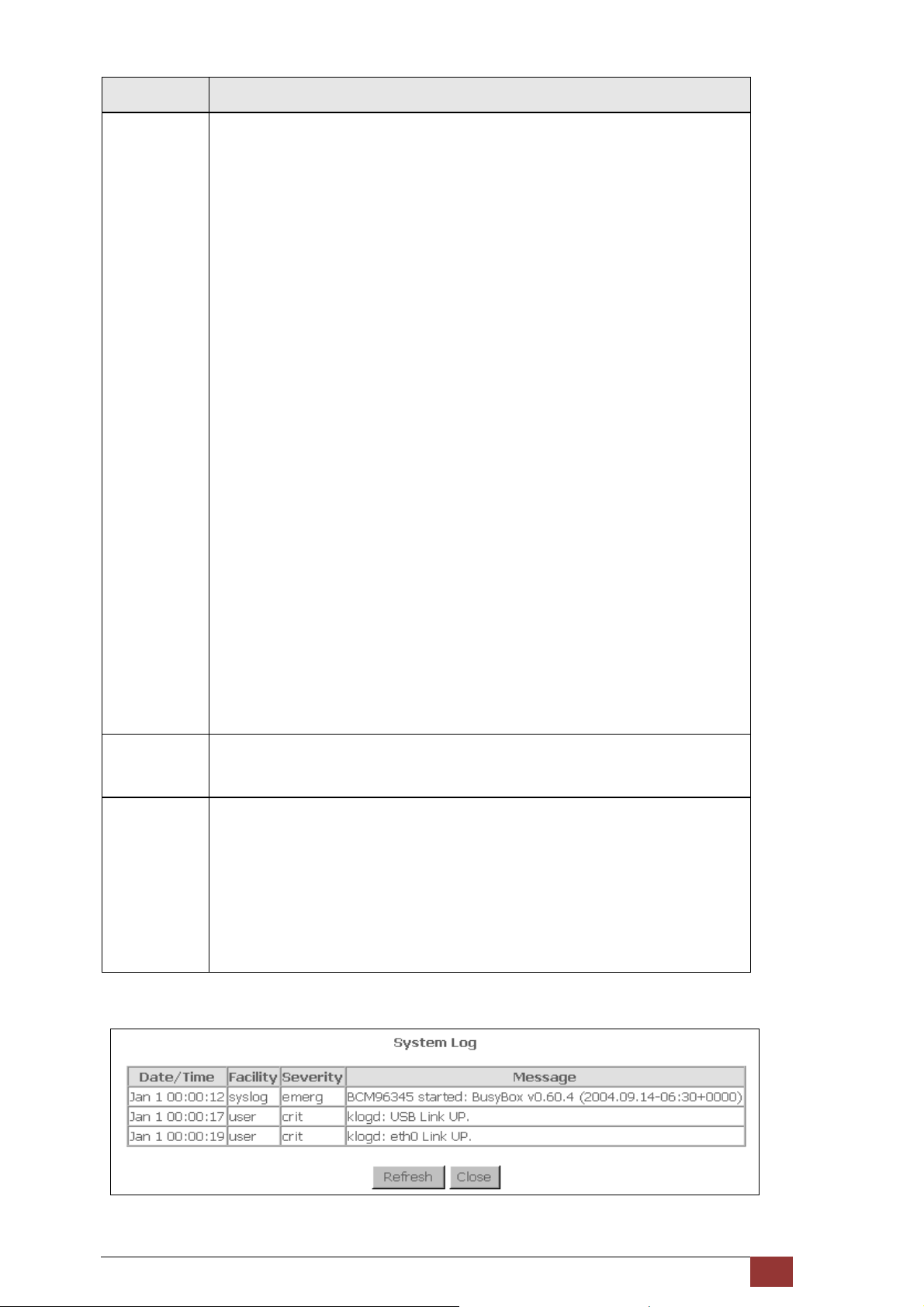
Option Description
Log Level Allows you to configure the event level and filter out unwanted events below this
level. The events ranging from the highest critical level “Emergency” down to this
configured level will be recorded to the log buffer on the router’s SDRAM. When
the log buffer is full, the newer event will wrap up to the top of the log buffer and
overwrite the old event. By default, the log level is “Debugging”, which is the
lowest critical level.
The log levels are defined as follows:
• Emergency = system is unusable
• Alert = action must be taken immediately
• Critical = critical conditions
• Error = Error conditions
• Warning = normal but significant condition
• Notice= normal but insignificant condition
• Informational= provides information for reference
• Debugging = debug-level messages
Emergency is the most serious event level, whereas Debugging is the least
important. For instance, if the log level is set to Debugging, all the events from
the lowest Debugging level to the most critical level Emergency level will be
recorded. If the log level is set to Error, only Error and the level above will be
logged.
Display Level Allows the user to select the logged events and displays on the View System Log
window for events of this level and above to the highest Emergency level.
Mode Allows you to specify whether events should be stored in the local memory, or be
sent to a remote system log server, or both simultaneously. If remote mode is
selected, view system log will not be able to display events saved in the remote
system log server.
When either Remote mode or Both modes is configured, the WEB UI will prompt
the user to enter the Server IP address and Server UDP port.
STEP 3: Click V iew System Log. The results are displayed as follows.
Proscend 130 ADSL2+/VDSL2 WLAN Router User Manual V0.02 95
Page 97
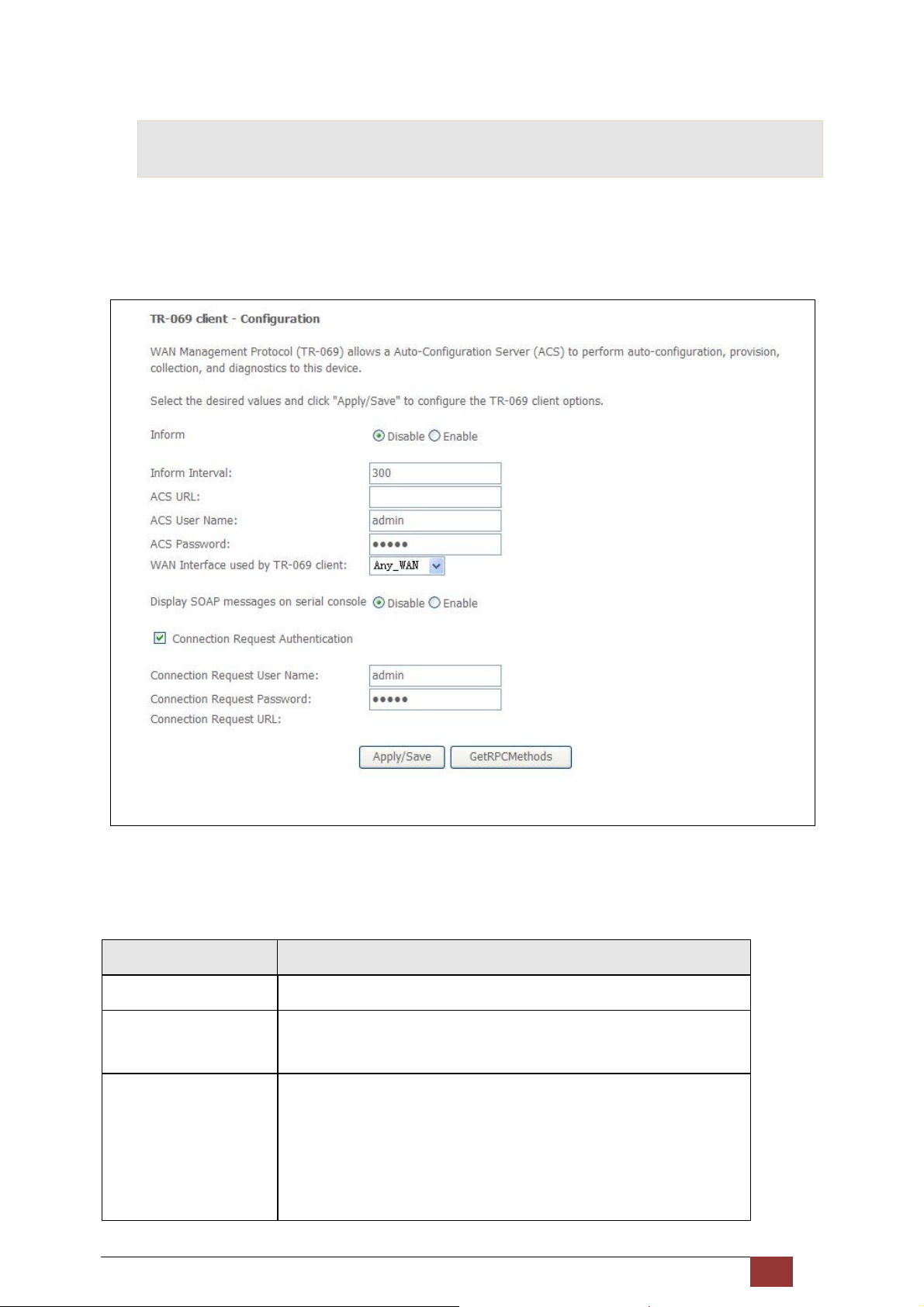
8.3 TR-069 Client
WAN Management Protocol (TR-069) allows an Auto-Configuration Server (ACS) to perform auto-configuration,
provision, collection, and diagnostics to this device. Select desired values and click Apply/Save to configure
TR-069 client options.
The table below is provided for ease of reference.
Option Description
Inform Disable/Enable TR-069 client on the CPE.
Inform Interval The duration in seconds of the interval for which the CPE MUST attempt
to connect with the ACS and call the Inform method.
ACS URL URL for the CPE to connect to the ACS using the CPE WAN Management
Protocol. This parameter MUST be in the form of a valid HTTP or HTTPS
URL. An HTTPS URL indicates that the ACS supports SSL. The “host”
portion of this URL is used by the CPE for validating the certificate from
the ACS when using certificate-based authentication.
Proscend 130 ADSL2+/VDSL2 WLAN Router User Manual V0.02 96
Page 98
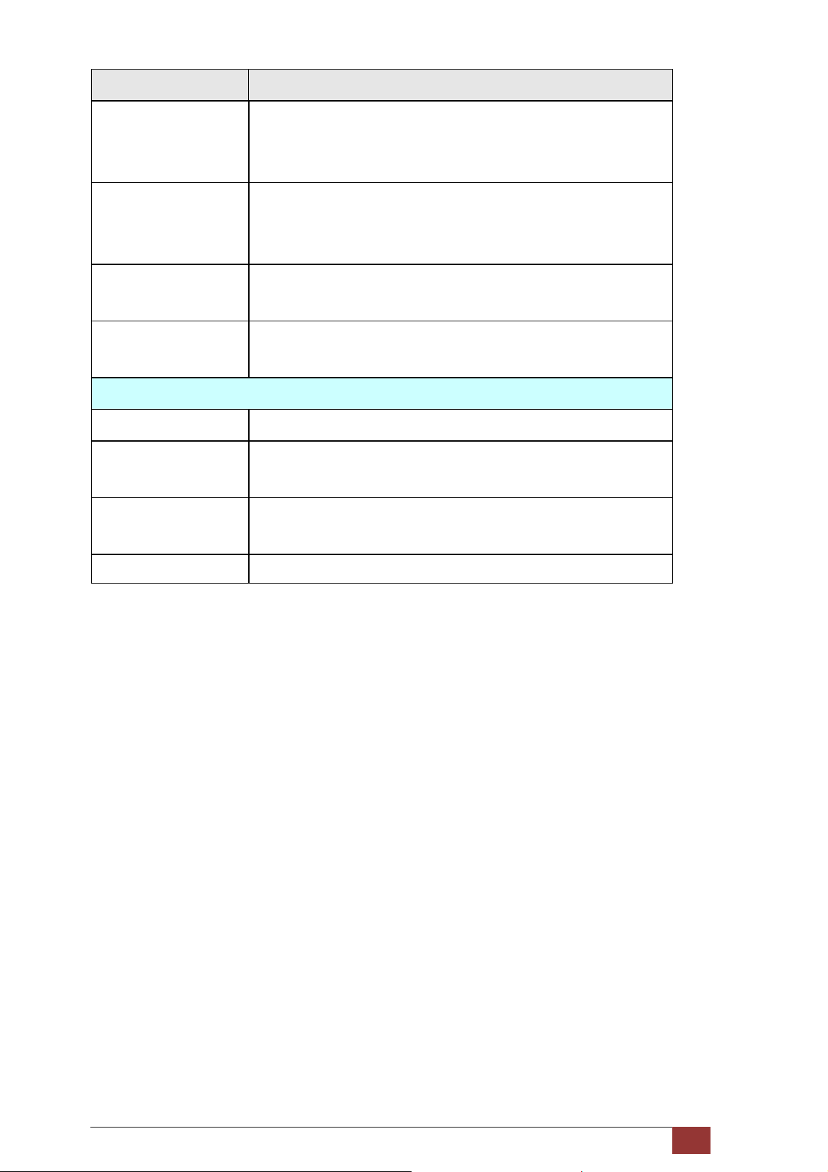
Option Description
ACS User Name Username used to authenticate the CPE when making a connection to
the ACS using the CPE WAN Management Protocol. This username is
used only for HTTP-based authentication of the CPE.
ACS Password Password used to authenticate the CPE when making a connection to
the ACS using the CPE WAN Management Protocol. This password is
used only for HTTP-based authentication of the CPE.
WAN Interface used by
TR-069 client
Display SOAP messages
on serial console
Connection Request
Authorization Tick the checkbox to enable.
User Name Username used to authenticate an ACS making a Connection Request to
Password Password used to authenticate an ACS making a Connection Request to
URL IP address and port the ACS uses to connect to Proscend 130.
The Get RPC Methods button forces the CPE to establish an immediate connection to the ACS. This may be
used to discover the set of methods supported by the ACS or CPE. This list may include both standard TR-069
methods (those defined in this specification or a subsequent version) and vendor-specific methods. The
Choose Any_WAN, LAN, Loopback or a configured connection.
Enable/Disable SOAP messages on serial console. This option is used for
advanced troubleshooting of the device.
the CPE.
the CPE.
receiver of the response MUST ignore any unrecognized methods.
Proscend 130 ADSL2+/VDSL2 WLAN Router User Manual V0.02 97
Page 99
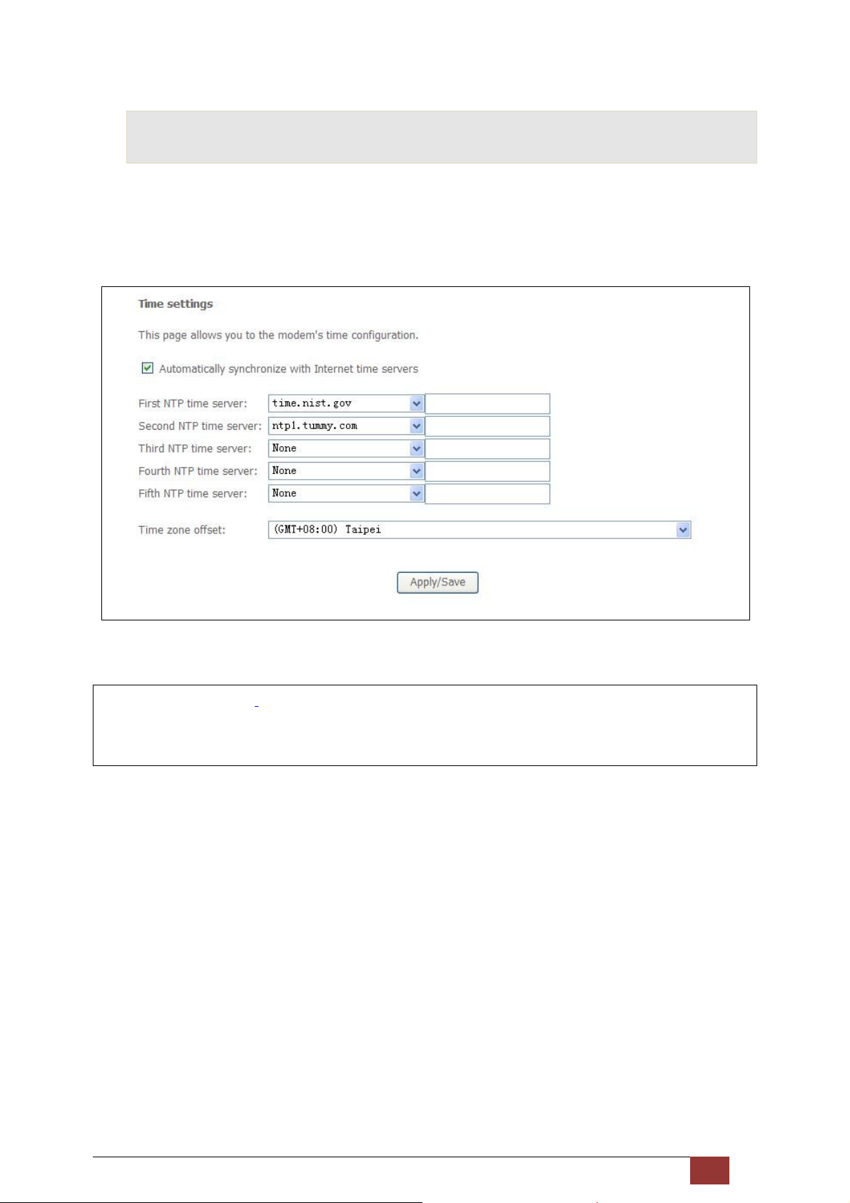
8.4 Internet Time
This option automatically synchronizes the router time with Internet timeservers. To enable time
synchronization, tick the corresponding checkbox , choose your preferred time server(s), select the correct
time zone offset, and click Save/Apply.
NOTE: Internet Time must be activated to use Parental Control.
In addition, this menu item is not displayed when in Bridge mode since the router would not be
able to connect to the NTP timeserver.
Proscend 130 ADSL2+/VDSL2 WLAN Router User Manual V0.02 98
Page 100
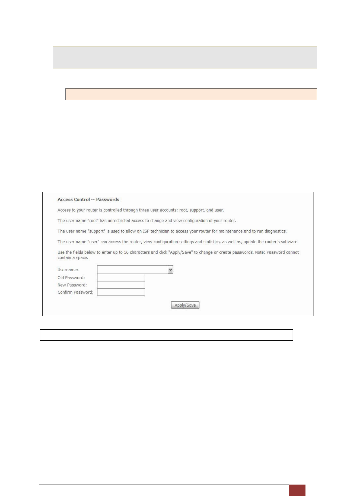
8.5 Access Control
8.5.1 Passwords
This screen is used to configure the user account access passwords for the device. Access to the Proscend 130
is controlled through the following three user accounts:
root - unrestricted access to change and view the configuration.
support - used for remote maintenance and diagnostics of the router
user - can view configuration settings & statistics and update firmware.
Use the fields below to change password settings. Click Save/Apply to continue.
NOTE: Passwords can be up to 16 characters in length.
Proscend 130 ADSL2+/VDSL2 WLAN Router User Manual V0.02 99
 Loading...