


37" Sound Bar Bluetooth with Optical
PLEASE READ BEFORE OPERATING THIS EQUIPMENT
INSTRUCTION MANUAL
MODEL:PSB3751
SAFETY INSTRUCTIONS
WARNING:Changes or modifications to this unit
not expressly approved by the party responsible
for compliance could void the user’s authority to
operate the equipment.
NOTE: This equipment has been tested and
found to comply with the limits for a Class B
digital device, pursuant to Part 15 of the FCC
Rules. These limits are designed to provide
reasonable protection against harmful interference
in a residential installation. This equipment
generates, uses, and can radiate radio frequency
energy and, if not installed and used in
accordance with the instructions, may cause
harmful interference to radio communications.
However, there is no guarantee that interference
will not occur in a particular installation. If this
equipment does cause harmful interference to
radio or television reception, which can be
determined by turning the equipment off and on,
the user is encouraged to try to correct the
interference by one or more of the following
measures:
•
Reorient or relocate the receiving antenna.
Increase the separation between the
equipment and receiver.
Connect the equipment into an outlet on a
circuit different from that to which the receiver
is connected.
Consult the dealer or an experienced radio/TV
technician for help.
•
•
•
FCC Warnings
FCC NOTICE:
To assure continued compliance, follow the attached
installation instructions and use only shielded cables
when connecting to other devices. Modifications not
authorized by the manufacturer may void user’s
authority to operate this device.
1
2
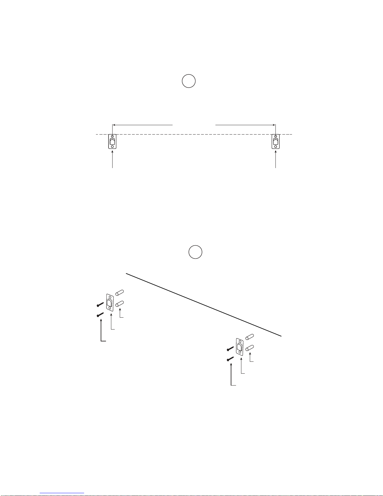
MOUNTING
1. Follow the figure 1 above to determine the positions where the screws should be mounted.
Make sure the two brackets are mounted in the same level.
2. Insert the fixing plugs into the screw holes and insert screws to fix the metal bracket onto the
wall.
3
1
734 mm
+/- 3 mm
Metal Bracket Metal Bracket
2
Metal Bracket
Metal Bracket
Fixing Plug
Screw
Wall
Fixing Plug
Screw

3. Hang the unit on the wall
Note:
The gap between the metal bracket and plastic mounting holder on the rear of the unit is designed
for simple mounting, which will make the unit movable.
4
3
Unit
Wall
Metal Bracket
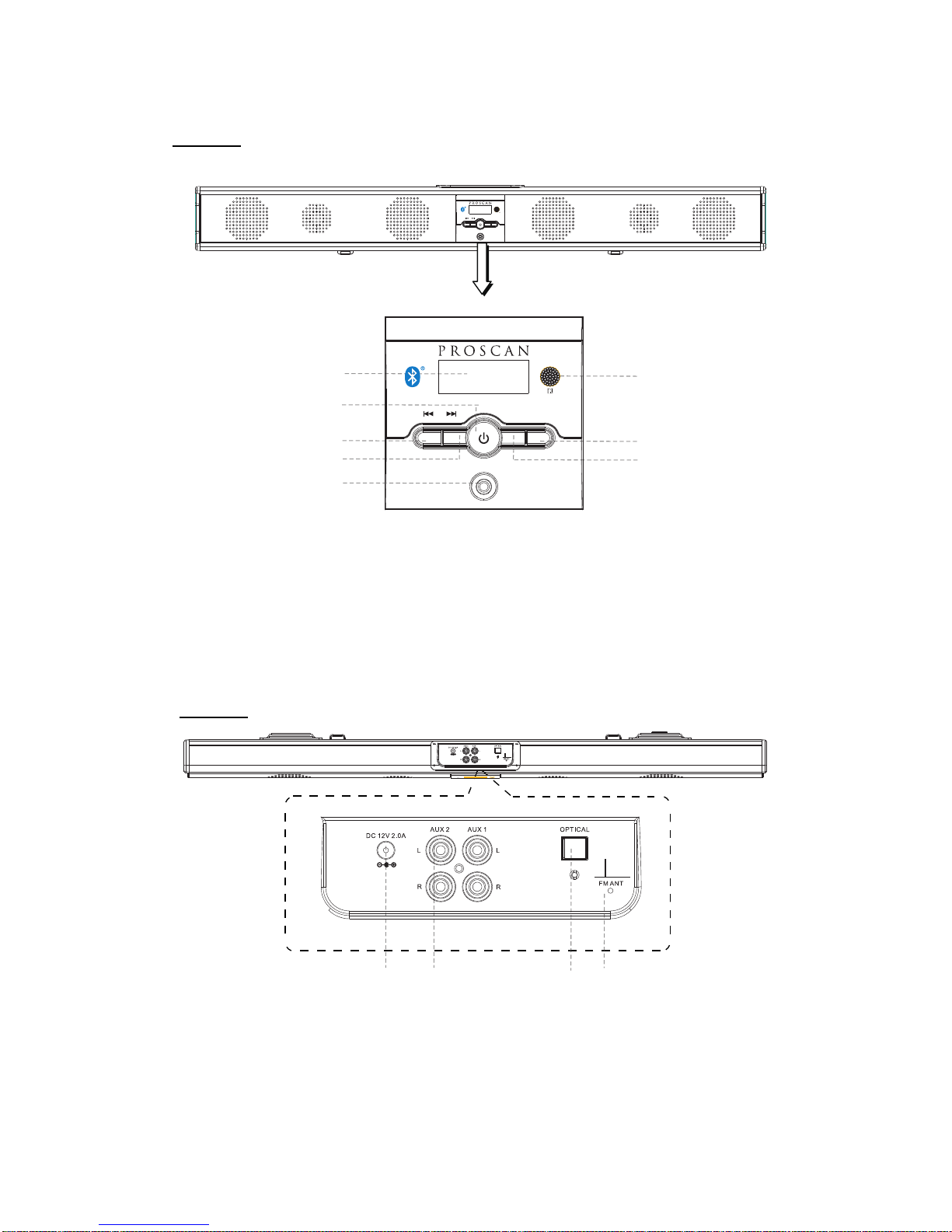
PRODUCT OVERVIEW
5
1
2
3
4
6
7
8
VOL- VOL+
AUX IN 1
MODE
5
2. Standby/MODE Button
JackIN1
10 11 12 13
12.
Audio Input Jacks
10.DC IN Jack
5. AUX
Button7.
3. Button
8. Volume - Button
4. Tune +Button
1. LCD Display
6. Remote Sensor
11.RCA
VOL- VO L+
AUX IN 1
MODE
Front View
13. FM Antenna
Optical Jack
Volume +
Tune -
TUN- T UN+
TUN- TUN+
Top View
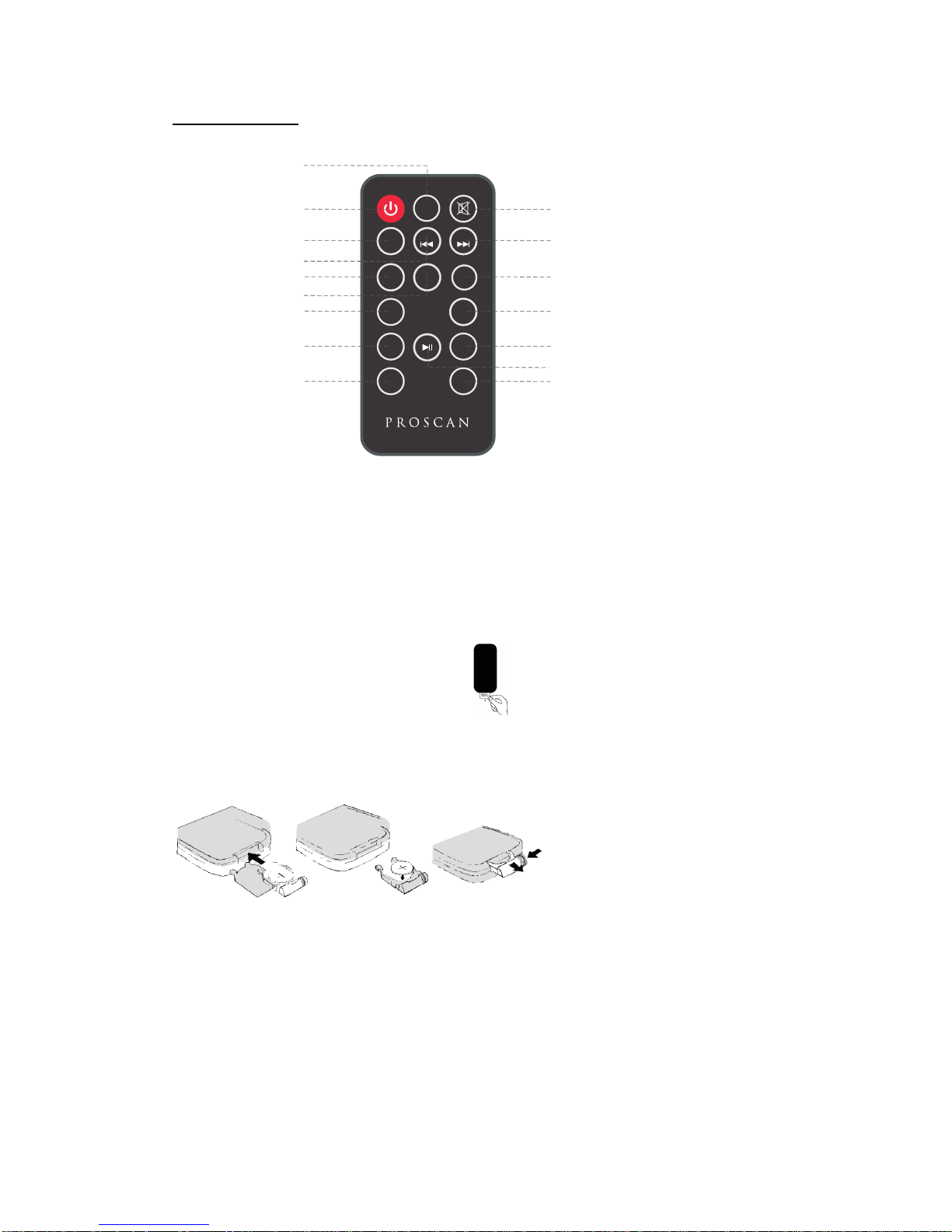
Remote Control
BATTERY INSTALLATION
- Before installation
Remove and discard the insulation tab.
-Replace battery for the remote control
1. Push and slide out the battery holder as Figure 1 below.
2. Replace the battery with a new CR2025 button cell with the polarity (+) side upward.
3. Slide into the battery holder.
Battery precautions
• Never recharge the batteries, apply heat to them or take them apart.
• Attention should be drawn to the environmental aspects of battery disposal.
• If the remote control is not going to be used for a long time, remove the battery
to avoid damage caused by battery leakage corrosion.
6
2
3
5
7
VOL+
FM SCAN
TUN-
M+
EQ
VOL-
BASS- BASS+
TREBLE-
TREBLE+
TUN+
8
9
4
6
1
10
11
12
13
14
16
15
CLOC K
MODE
Button
on
Button
6. EQ Butt
1.MODE
2. Standby Button
7. VOL- (Volume-) Button
13. VOL+ (Volume+) Button
5. M+ Button
10. Mute Button
16. TREBLE+ Button
11. TUN+ Button
12.
3. FM SCAN Button
8. BASS- Button
14. BASS+ Button
4. TUN - Button
9. TREBLE- Button
15. Play/Pause Button
shall not be exposed to excessive heat such as sunshine, fire or the like.
• Do not throw the batteries in fire!
•Battery
CLOCK
( Preset recall )

POWER CONTROL
- To turn the unit on
·
·
- To turn the unit off
·
NOTE:
If the unit is not used for a long period of time, disconnect the power adapter.
TIME SETTING
1. Place the unit to standby mode.
digit will flash.
FM RADIO
display.
- Search and store the stations
forward or backward. The unit will stop if a
select the place you want the station stored to. Press FM SCAN button to confirm. Or
2. Hold FM SCAN button then release the unit will search and store the stations automatically.
- Listen to the preset stations
PressM+buttonrepeatedlytoselectthedesiredpresetstationstolistento.
7
MODE
Power on the unit and press
button repeatedly until the FM frequency appears on the
Connect the supplied power adapter.
7. Press CLOCK button on the remote control to confirm the minute setting.
5. Press CLOCK button on the remote control to confirm the hour setting and the minute
3. CLOCK button on the remote control and the hour digit flashes.
Press STANDBY button to turn on the unit.
Press STANDBY button on the remote control or hold STANDBY button front of
the unit.
in the
2. Hold CLOCK button on the remote control to switch 12 or 24 hour system.
Press
4.Then press TUN+ or TUN- button on the unit or remote control to adjust the hour.
if in 12 hour system, when the time arrives 12:00, the "PM" will appear on display.
6. Then press TUN TUN - button on the unit or remote control to adjust the minute.+ or
1. Hold TUN + or TUN-button to search stations
station is found. Then press FM SCAN button, “CHXX” will flash and then use
button to
TUN + or TUN
-

AUX IN
- AUX IN source may include:
·
- AUX IN connection:
1. Connect a stereo 3.5mm jack cable (supplied) between the headphone or LINE/Audio output of
Set your personal audio player/computer to play.
NOTE: If there is no sound or if the volume is not loud enough, you may increase the setting on
the source.
- During playback
·Press MUTE button to turn off the sound. Press again to resume the sound.
·Press VOLUME+/- buttons to adjust the volume level.
·Press BASS+/- buttons to adjust bass level.
·Press TREBLE+/-buttons to adjust treble level.
·Press EQ button to switch between POP/JAZZ/CLASSIC/ROCK/NORMAL.
8
MODE2. Power on the unit and press button repeatedly until "AUX1" appears on the display.
the personal audio player and the jack on the front of the unit.AUX IN1
POWER
RESET
Computer
MP3
Supplied audio
connection cable
To AUX IN 1 Jack
Connect to the output
socket of external
audio devices (MP3,
Computer,ext.)
on the unit
TUN- TUN+
VOL- VOL+
AUX IN 1
MODE
Personal audio players,
computers or laptops
 Loading...