

Page 1
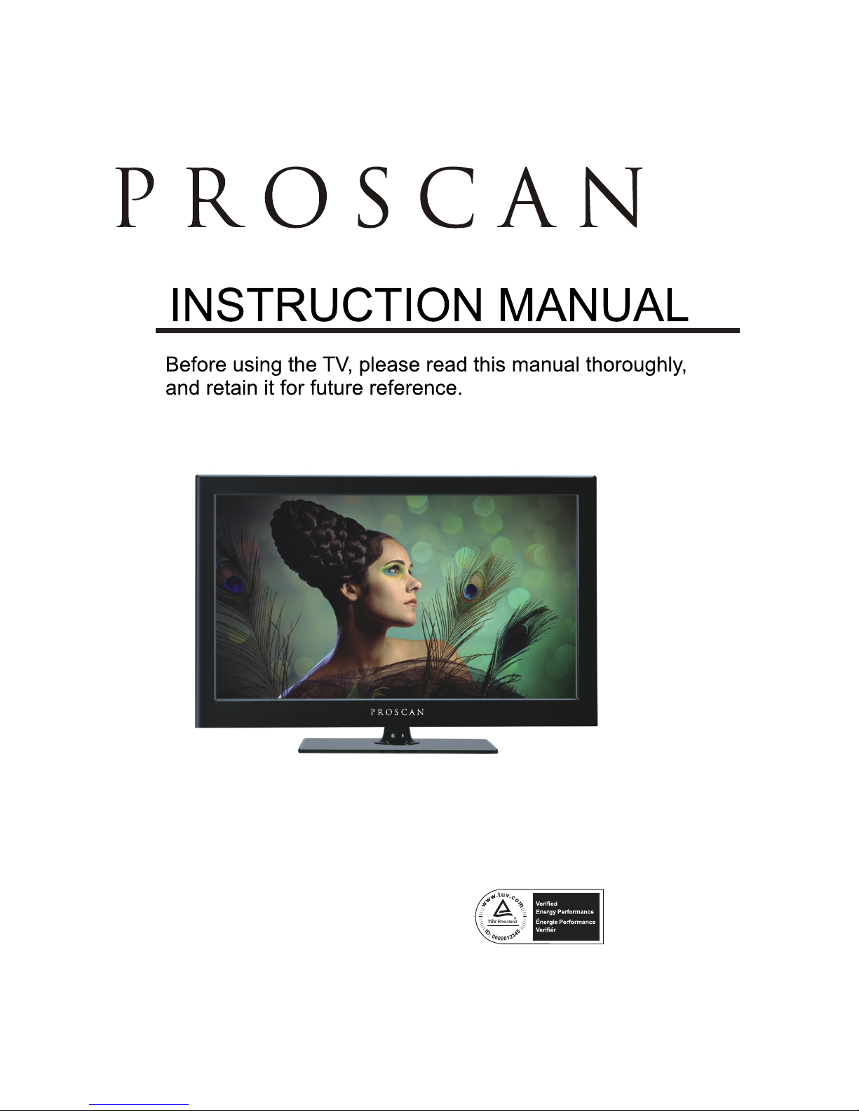
Model: PLED4274A
Page 2
CONTENTS
13
13
15
19
21
24
1
2
2
3
3
6
7
3
4
8
9
7
8
8
9
9
4
5
5
6
11
12
12
SAFETY
PRECAUTION
IMPORTANT
SAFETY
INSTRUCTION
ACCESSORIES
GETTING
STARTED
5
CONTROL
REFERENCE
GUIDE
WALL MOUNT
INSTALLATION
INITIAL SETUP
TV SETUP
CONNECTIONS
Remote Control
Front View
Back View
Side View
Antenna Connection
AV Connection
Y Pb Pr Connection
HDMI Connection
VGA Connection
Headphone Connection
Power Cord Connection
Coax(SPDIF) Connection
Putting The Unit On A Proper Place
Turning The Unit On For The First Time
Source selection
Main menu
Picture Menu
Sound Menu
Channel Menu
Parental Control
Setup Menu
Other Menu
1
English
10
7
9
28
30
Page 3

CONTENTS
31
10
33
11
12
34
DISPLAY
MODE
SPECIFICATION
TROUBLESHOOTING
GUIDE
PC Formats
Video Formats
TV Symptom
SAFETY CLASS :This is an IEC safety class I product
and it must be grounded for safety.
32
Page 4
*
SAFETY PRECAUTION
CAUTION
•
•
•
WAR NING:
PLACEMENT INFORM ATION
SAFETY INFORMATION
RATING PLATE LOCATION
FCC STATEMENTS
WARNING:
1
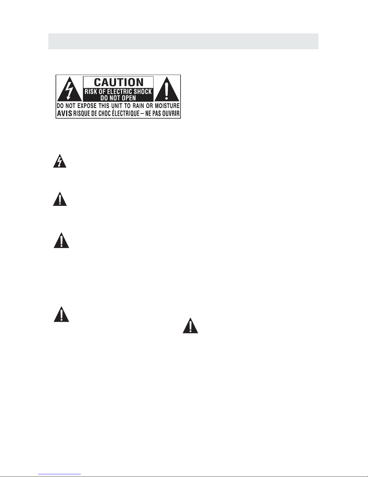
CAUTION MA RKI NG WA S LOC ATED AT THE REAR
OF THE APPAR ATU S.
WARNING: TO REDUCE THE RISK OF ELECTRIC
SHOCK,DO NOT REMOVE COVER(OR BACK)
NO USER SERVICEABLE PARTS INSIDE.
REFER SERVICING TO QUALIFIED SERVICE
PERSONNEL.
The lightning flash with arrowhead symbol,
within an equilateral triangle,is intended to
alert the user to the presence of uninsulated
“dangerous voltage”within the product's enclosure
that may beof sufficient magnitude to constitute a
risk of electric shock to persons.
The exclamation point within an equilateral
Triangle is intended to alert the user to
The presence of important operating and
maintenance (servicing) instructions in the literature
accompanying the appliance.
DANGER OF EX PLO SIO N IF BA TTE RY IS
INCORREC TLY R EPL ACE D. RE PLACE ONLY
WITH THE SAME OR EQ UIV ALE NT TY PE.
USE OF CONTR OLS O R ADJ UST MEN TS OR
PERFORMA NCE O F PRO CED URE S OTHER
THAN THOSE S PEC IFI ED MA Y RES ULT IN
HAZARDOU S RAD IAT ION E XPO SURE.
•
•
TO REDUCE TH E RIS K OF FI RE OR E LEC TRI C
SHOCK, DO NO T EXP OSE T HIS A PPL IAN CE TO
RAIN OR MOIS TUR E.
TO REVENT FI RE OR S HOC K HAZ ARD , DO NO T
EXPOSE THI S UNI T TO RA IN OR M OIS TUR E. DO
NOT PLACE OB JEC TS FI LLE D WIT H LIQ UIDS ON
OR NEAR THIS U NIT .
SHOULD ANY T ROU BLE O CCU R, DI SCONNECT
THE AC POWER C ORD A ND RE FER S ERV ICING
TO A QUALIFIED TE CHN ICI AN.
Do not use thi s uni t in pl ace s tha t are extremely
hot, cold, d ust y or hu mid .
Do not restr ict t he ai rfl ow of t his unit by placing it
somewher e wit h poo r air flow, by covering it with
a cloth, by pl aci ng it o n bed din g or carpeting.
When conne cti ng or d isc onnecting the AC power
cord, grip t he pl ug an d not t he co rd itself. Pulling
the cord may d ama ge it a nd cr eate a hazard.
When youar e not g oin g to us e the u nit for a long
period of ti me, d isc onn ect the AC power cord.
The rating p lat e is lo cat ed on t he rear of the unit.
NOTE: This u nit h as be en te ste d and found to comply
with the lim its f or a Cl ass B d igi tal device, pursuant
to Part 15 of th e FCC R ule s. Th ese l imits are designed
to provide r eas ona ble p rotection against harmful
interfer enc e in a re sid ential installation.
This unit ge ner ate s, us es an d can radiate radio
frequenc y ene rgy a nd, i f not i nstalled and used in
accordan ce wi th th e ins tru ctions, may cause harmful
interfer enc e to ra dio c omm unication. However, there
is no guaran tee t hat i nte rfe rence will not occur in a
particul ar in sta lla tio n. If this unit does cause harmful
interfer enc e to ra dio o r tel evision reception, which
can be deter min ed by t urn ing the unit off and on, the
user is enco ura ged t o try t o cor rect the interference
by one or more o f the f oll owi ng me asures:
- Reorient o r rel oca te th e rec eiving antenna.
- Increase t he se par ati on be tween the unit and
receiver .
-Connect t he un it in to an o utl et on a circuit different
from that to w hic h the r ece ive r is connected.
- Consult th e dea ler o r an ex perienced radio/TV
technici an fo r hel p.
Chang es or modificat ion s to this
unit no t expressly app rov ed by the party res ponsible
for com pliance could v oid t he user authori ty
to oper ate the unit.
•
•
•
•
Page 5

IMPORTANT SAFETY INSTRUCTIONS
2
1)Read thes e ins tru cti ons.
2)Keep thes e ins tru cti ons.
3)Heed a ll wa rni ngs .
4)Follow al l ins tru cti ons.
5)Do not use th is ap par atu s near water.
6)Clea n onl y wit h a dry c lot h.
7)Do not bloc k any v ent ila tion openings.
Install in a cco rda nce w ith the
manufact ure r's i nst ructions.
8)Do not inst all n ear a ny he at sources such
as radiato rs, h eat r egi ste rs, stoves, or
other appa rat us (I ncl uding amplifiers) that
produ ce he at.
9)Do not defe ct th e saf ety p urp ose of the
polar ize d or gr oun din g-type plug.
A polarize d plu g has t wo bl ades with one
wider than t he ot her .
A groundin gty pe pl ug ha s two blades
and a third gr oun din g pro ng.
The wide bla de or t he th ird p rong is
provided f or yo ur sa fet y.
If the provi ded p lug d oes n ot fit into your
wall outle t, co nsu lt an e lec trician for
replacem ent o f the o bso lete outlet.
10)Pro tec t the p owe r cor d from being walked on
or pinched p art icu lar ly at plugs, convenience
receptac les , and t he po int where they exit
from the app ara tus .
11)Only use a tta chm ent s / acc essories specified
by the manuf act ure r.
12)Use only w ith t he ca rt, s tan d,
tripod, br ack et, o r tab le
specifie d by th e man ufa ctu rer,
or sold with t he ap par atu s.
When a cart is u sed , use c aut ion w hen
moving the c art / a ppa rat us co mbination to
avoid inju ry fr om ti p-o ver.
13)Unplug t his a ppa rat us during lightning
Storms or wh en un use d for l ong periods of
time.
14)Refer al l ser vic ing t o qualified service
personne l. Se rvi cin g is required when the
apparatu sha s bee n dam aged in any way,
such as the po wer c ord o r plu g is damaged,
liquid has b een s pil led o r objects have fallen
into the app ara tus , the a ppa ratus has been
exposed to r ain o r moi stu re, does not operate
normally , or ha s bee n dro pped.
15)To preve nt el ect ric s hock, ensure the grounding
pin on the AC co rd po wer p lug i s securely
connecte d.
Page 6
ACCESSORIES
Please check and identif y the supplied accessories.
.. ... ........ ... ........ ... ........ ... ........ ... ........ ... ........ ... ........ ... ........ ... ........ ... .... . ........
.. ... ........ ... ........ ... ........ ... ........ ... ........ ... ........ ... ........ ... ........ ... ........ ... ........
.. ... ........ ... ........ ... ........ ... ........ ... ........ ... ........ ... ........ ... ........ ... ........ ... ...
GETTING STARTED
USING THE REMOTE CONTROL
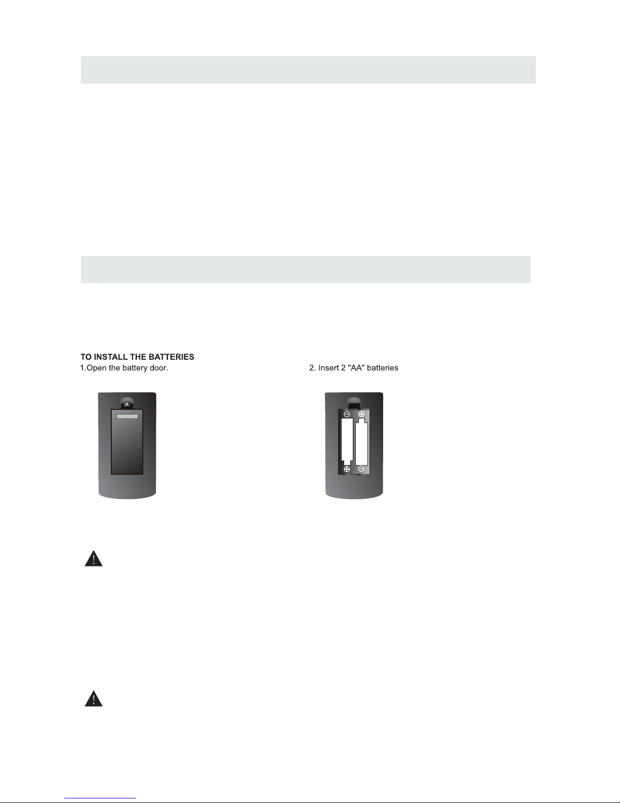
BATTERY REPLACEMENT
CAUTION
: Da nge r of ex plosion if battery is in cor rec tly replaced.
NOT ES
WARNING :
3
x 2
x 1
x 1
x 1
Remote contro l ... ... ... ... ... ... ...................................... ... ... ... ... ... ... ... .....................................
Remote con tro l
Battery( AA)
Warranty C ard
Instruct ion M anu al
·Point the re mot e con tro l at the remote sensor located o n the u nit .
·When there i s a str ong a mbi ent light source, the perfor man ce of t he in frared remote sensor
·may be de gra ded , cau sing unreliable operatio n.
·The recomm end ed ef fec tive distance for remote ope rat ion i s abo ut 16 feet (5 meters).
When the bat ter ies b eco me weak, the operating dista nce o f the r emo te control is greatly
reduc ed an d you w ill n eed to replace the batteries .
·If the remot e con tro l is no t going to be used for a long time, re mov e the b att eries to avoid
damag e cau sed b y bat tery leakage corrosion.
·Do not mix old a nd ne w bat teries. Do not mix ALKALINE, stan dar d (CA RBO N-ZINC) or
recha rge abl e (NI CKEL-CADMIUM) batterie s.
·Alway s rem ove b att eries as soon as they become wea k.
·Weak batte rie s can l eak a nd severely damage the re mot e con tro l.
Do not dispo se ba tte rie s in a fire. Batteries may explo de or l eak .
Batterie s sha ll no t be ex posed to excessive heat such a s sun shi ne, f ire or the like.
Base stand and 6 screws
.. ... ........ ... ........ ... ........ ... ........ ... ........ ... ........ ... ........ ... ........ .
x 1
Screw driver
.. ... ........ ... ........ ... ........ ... ........ ... ........ ... ........ ... ........ ... ........ ... ........ ... ........
x 1
Page 7
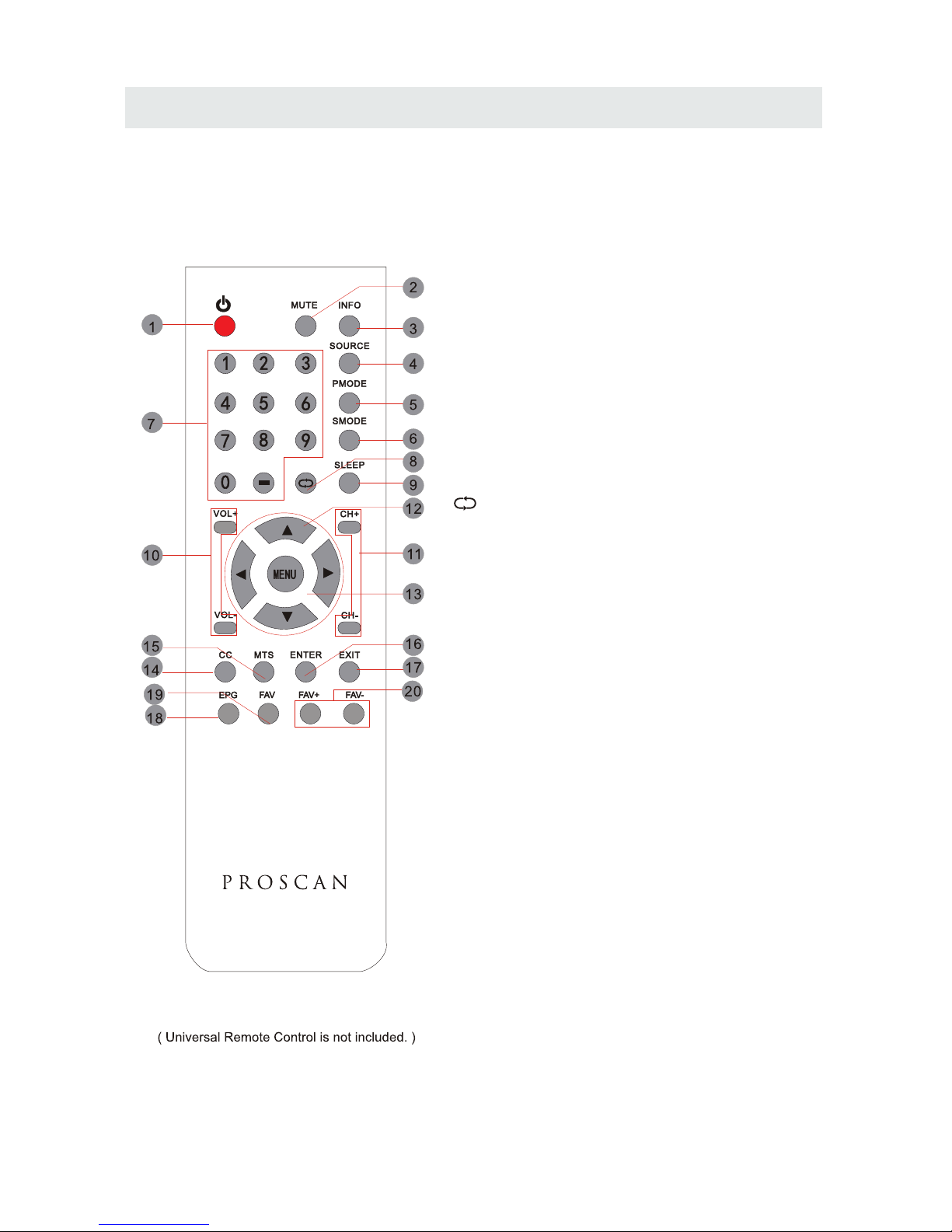
CONTROL REFERENCE GUIDE
4
REMOTE CONTROL
Universal Remote Code: 1218
1.STANDBY
To switch on the TV or make the TV into
standby mode.
2.MUTE
Press this button to mute or restore sound.
3.INFO
Show the information of the program you are watching.
4.SOURCE
Press this button to select an input source.
5.PMODE
Press this button to select a picture mode for different
picture qualities.
6.SMODE
Press this button to select sound setting for different
sound effects.
7.0-9
Allows you to change the channel of the TV.
8.
Switches back and forth between the current and
previous channels.
9.SLEEP
To select the amount of time before your TV turns
Off automatically.
10.VOL+/VOLIncreases/Decreases the Volume control.
11.CH+/CHSkips to the next/previous channel on TV mode.
12.UP/DOWN/LEFT/RIGHT
Moves the cursor upward/downward/to the left/to the right
when making a selection.
13.MENU
Displays the OSD Menu of the TV.
14.CC
Press the button to enter into the CC mode.
15.MTS
To change among STEREO, MONO and SAP. If there is no
second language available for the signal received, LCD
Display audio will output to mono.
16.ENTER
Press to confirm selections on a menu screen.
17.Exit
Press this button to exit the on screen display.
18.EPG
Press this button to select the electronic programme
guide in DTV mode.
19. FAV
Press this button to show the favourite list.
20. FAV+/FAVPress this button to go through the FAV channel list.
Page 8
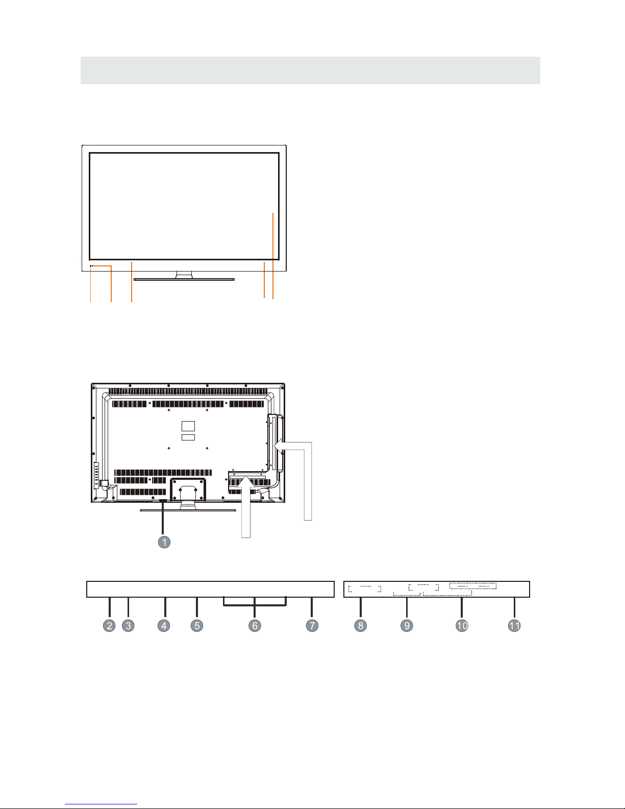
CONTROL REFERENCE GUIDE
BACK VIEW
FRONT VIEW
1.Color Screen
2.Standby Indicator
Indicates whether the unit is ON
or in STANDBY (OFF) mode.
Light in red: The unit is in STANDBY.
Light in blue:The unit is turned ON.
3.Remote Sensor
Do not block this sensor or the
remote control will not work.
4. Speakers
5
1.Power cord
2.Coax OUT Jack
3.TV ANTENNA Terminal
4.VGA IN Jack
5.PC AUDIO IN Jack
6.HDMI IN Jack
7.Service Port
8.AUDIO OUT Jack
(Audio out- This connection is for sending out
analog audio signal to the 2nd equipment.Red
is for Right Channel, white is for Left Channel.)
9.AV (VIDEO/ AUDIO R/L) IN
10.COMPONENT IN Jack
11.Headphone Jack
3
2
44
1
COAX RF VGA
PC
AUDIO
HDMI1 HDMI2 HDMI3 Service Port
Headphone
R
AUDIO OUT
L
AUDIO IN
COMPONENT
VIDEO
R L
AV
Y Pb Pr
Page 9
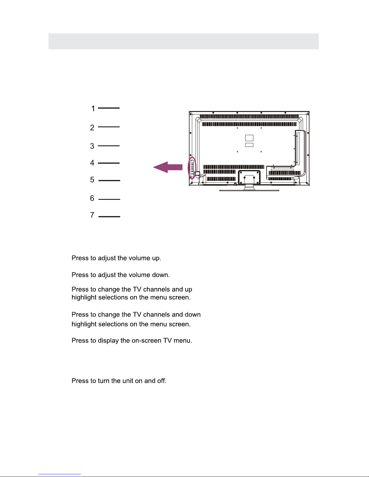
CONTROL REFERENCE GUIDE
6
BACK VIEW
Press to select the input source of the TV,
and then, press to confirm.
VOL-
VOL+
CH-
CH+
MENU
SOURCE
STANDBY
1. VOL+ Button
2. VOL- Button
3. CH+ Button
4. CH- Button
5. MENU Button
6. SOURCE Button
7. STANDBY Button
Page 10
CONNECTIONS
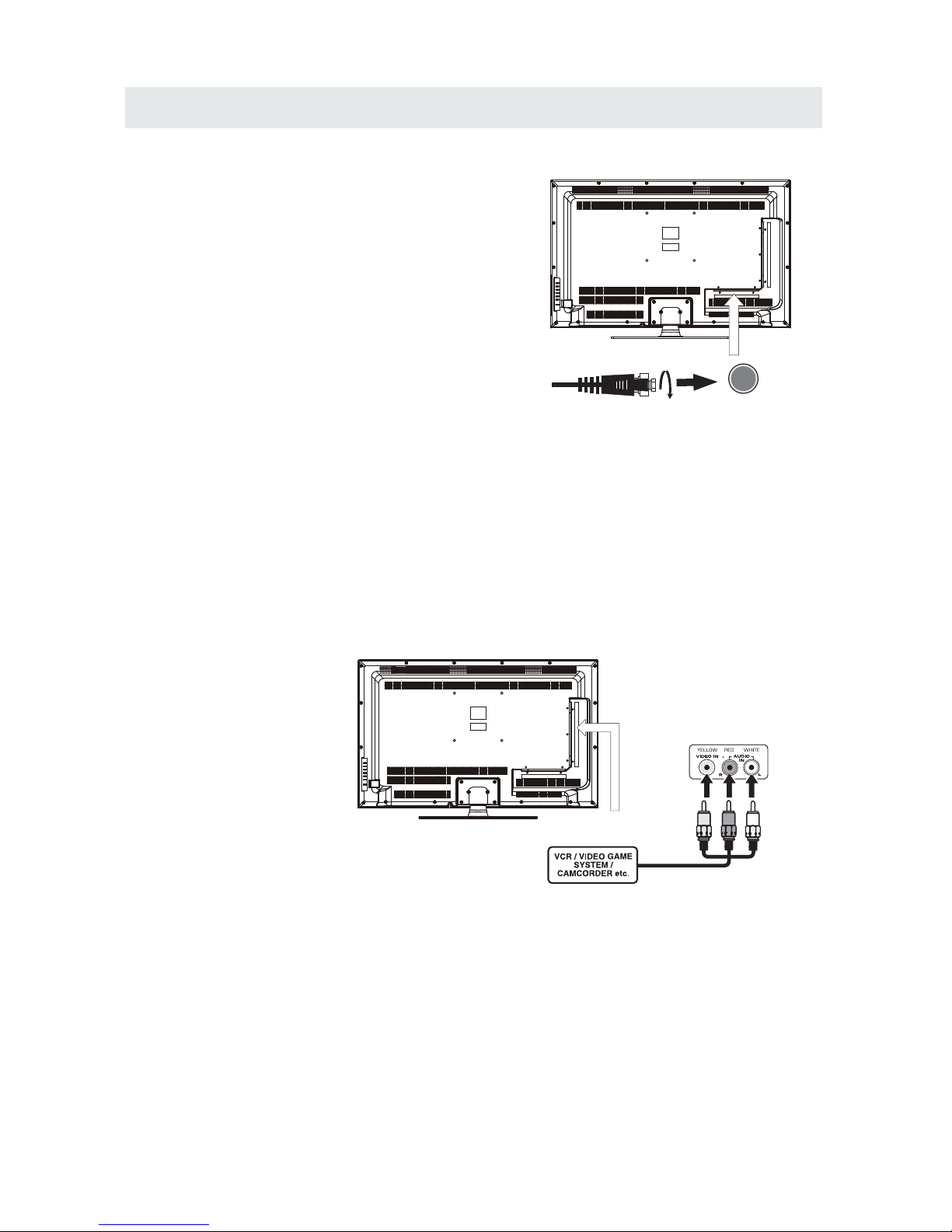
CONNECTING A TV ANTENNA / CABLE / S A TELLITE
To vi ew television channels correct ly, a signal must
be received from one of the following sources:
- An indoor or outdo or aeria l antenna
- A ca ble system
- A satel lite sys tem
Fo r re ceivi ng over-the-air TV broadcasts, we
recom mend that you use an exte rnal fi xed antenna.
Sh ould you req uire the use of a tempo rary ante nna,
pl ease ens ure that you pu rchase an anten na with
su ffici ent ability to recei ve in weak signal areas .
On ly when you are in close proximity to a tran smitt er
wi ll a te mpora ry an tenna reproduce a signal as
st rongly as a fixed antenna .
To co nnect to other equipment such as a VCR, cam corder, satel lite system or cable, etc.
CONNECTING AN A/V DEVICE
NOTE
CONNECTING DEVICES WITH A COMPOSITE (YELLOW RCA-TYPE)
VIDEO OUTPUT
Connecting to a VCR / Video Game System / Camcorder
AUDIO VIDEO OUT
NOTE
To con nect A/ V devic es such a s a VCR , video game system or ca mcord er.
Co nnect th e AU DIO / VID EO cable (n ot inclu ded) as sho wn.
Ma ke su re you connect the cable fro m the oth er equi pment ( and ) to this u nit
Pl ease refer to the use r manua l
fo r the other equi pment f or
mo re information.
Sa tel lit e, cab le or TV an ten na
ca ble t o TV ANTENNA
termi nal (c able not included )
To AU DIO / VID EO
IN j acks
To AU DIO / VID EO
OU T ja cks
7
(AV in)
Page 11
CONNECTIONS
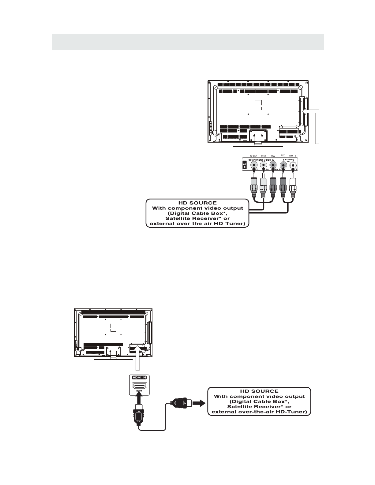
CONNECTING A HIGH-DEFINITION (HD) SOURCE USING CONNECTION
NOT E
COMPONENT
High- Def ini tion (HD) Devic es wit h component video out put mu st be con nec ted to th e Y input.
Conne ct the co mpo nent video cable and audio cable (n ot inc lud ed) as sh own.
Ma ke sure you con nec t the compon ent v ideo cable a nd au dio cable from the oth er equipment
When connecti ng a DVD player to the telev ision,
the picture resol ution is solely depend ent upon
the re solution suppo rted by the DVD pl ayer attached.
DVD player resolutions vary from 480 i to 1080p .
and this television can su pport DVD players up to
a maximum resolution of 1080p.
PbPr
* May require a subscription
fo r receiving HD ch annel s,
ch eck with you r cable/satellite
se rv ice pr ovide r for details.
To CO MPO NENT
VI DEO O UT jacks
CONNECTING A HIG H-DEFINITION (HD) SOURCE USING HDMI CONNECTION
HDMI (Hi gh Def inition Multim edi a Interface) suppo rts bo th vid eo and audio on a sin gle di gital connection
fo r use w ith DVD players , DTV, se t-to p boxes and ot her d igital AV dev ice s. HD MI was devel ope d to provide
the te chn ologies of High Ba ndw idt h Digital Co nte nt Pro tec tio n (HDCP) as wel l as Digit al Visual In ter face
(D VI) i n one specif ica tion. HDCP i s use d to pr ote ct di gital content t ransmitted and receiv ed by
DVI-c omp liant or HDMIcomp lia nt displays.
HDMI has th e capability to support standard, en han ced or high-def ini tion video plus st andard to
multi -ch annel surround -so und audio. HD MI features include unc omp res sed di gital video , a ban dwi dth of
up to 2.2 gi gab ytes per second (w ith HDTV signal s), one connector (instead of several cab les an d
conne cto rs), and communic ati on between the AV source and AV device s such as DTVs.
To HDMI
IN jack
To HDMI
ja ckOUT
To COMPONENT
VIDEO IN jacks
AU DIO I N jacks
To COMPONENT AUDIO
OU T jac ks
Co nne ct the HDMI ca ble ( not includ ed) a s
sh own :
Ma ke sure you con nec t the cable from th e
so urc e equipment ( ) to this un it
( ).
HD MI OUT
HD MI IN
HDMI CABLE
(NOT INCLUDED)
(COMPONENT OUT and AUDIO OUT)to the unit COMPONENT IN.
COMPONENT IN
8
To COMPONENT
Page 12
CONNECTIONS
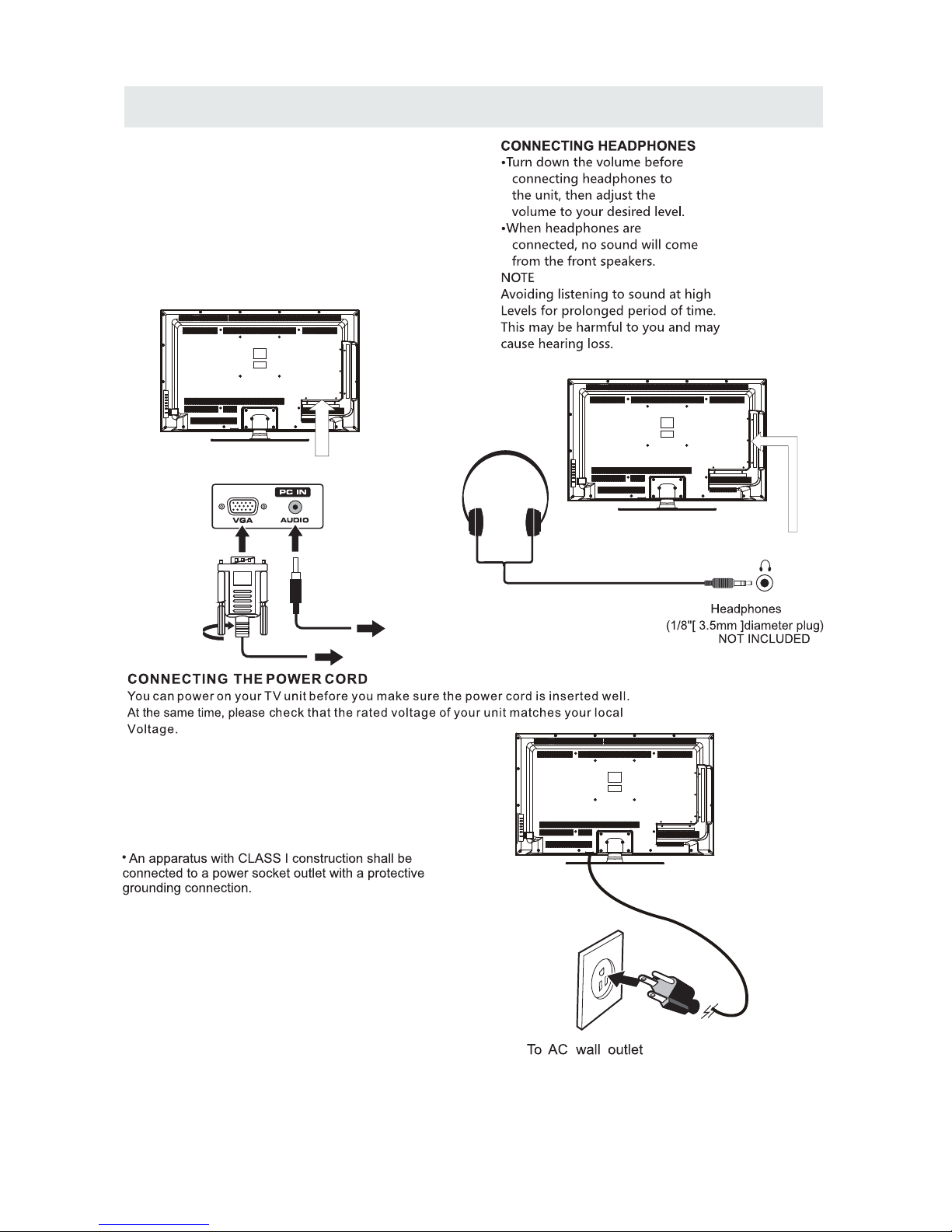
CONNECTI NG A
AUDIO - PC OUT
VGA AUDIO - PC IN
PC
VGA
Co nne ct the 15-pi n D- SUB PC/VGA co nnector
from you r co mputer to the 15 -pin D-SUB PC/ VGA
in put on th is unit using a mo nit or cable and an
au dio ca ble (not inc lud ed) as shown .
Ma ke sure you con nec t the cable from the com put er
( an d ) to this un it
( And ).
TO PC Connector
TO AUDIO OUT ja cks
NOT E
• Inser t the power plug fully into the socket outlet
If the power plug is loo se it could generate heat and
cause fire
Do not touch t he po wer plug with a wet hand
This may cause elect rical shock
Do not use any power cord other than that provided
with this TV This may cause fi re or ele ctrical shock
Do not damage the power cord
A damaged co rd may cause fire or electrical sho ck
• Do not move the TV with the cord plugged in the
socket outlet.
• Do not place a heavy object on th e cord or place
the cord near a high-temperature object.
• Do not twist the cord, b end it excessiv ely, or stretch it.
• Do not pull on the cord. Hold onto the power plug body when disconnecting cord.
• Do not use a damaged power plug or socket outlet.
.
( ,
.)
.
( .)
. ( .)
.
( ).
•
•
•
connected to prevent electrical shock.
Ensure that the power plug is easil y accessible.
Ensure the earth pin on the power plug is securely
•
•
9
Page 13
CONNECTIONS
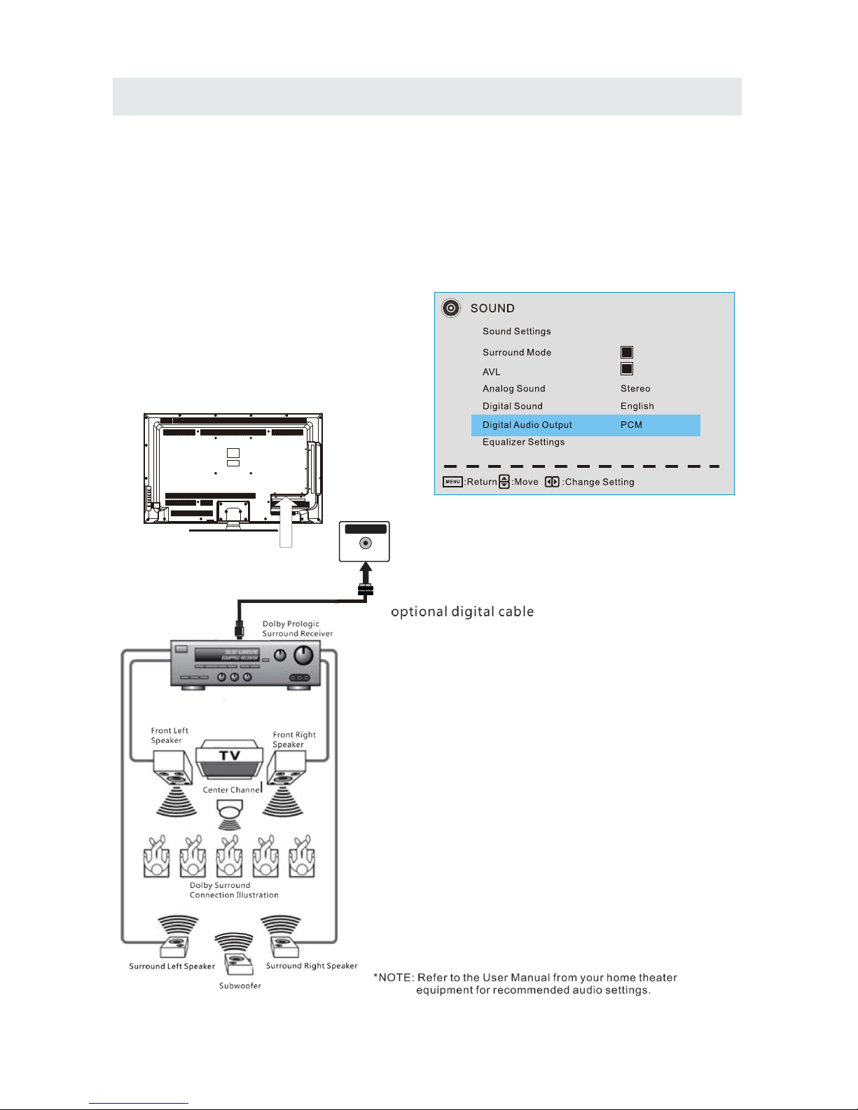
Connection to a Home Theater Audio System
For BEST audio performance
Connecting to a Home Theater System
Dolby Digital can deliver optimal 2 channel
stereo or surround sound with five discrete
full range channels plus a sixth channel for
a subwoofer.
Enjoy optimal sound reproduction from your
system with a Dolby Digital amplifier that
incorporates a digital coaxial input. Connect
an optional digital cable directly to the
television’s Coax audio output to listen
through all inputs except VGA.
(The VGA does not support digital audio)
How To Setup Digital Output
Press the MENU button on the remote control
Press the right ► arrow button to select SOUND
and Press ENTER to enter the submenu.
Press the down ▼ arrow button to highlight
Digital Audio Output and press ◄► to
change setting from PCM, Raw or Off.
10
Coax
SPD IF OUT
Page 14
Page 15
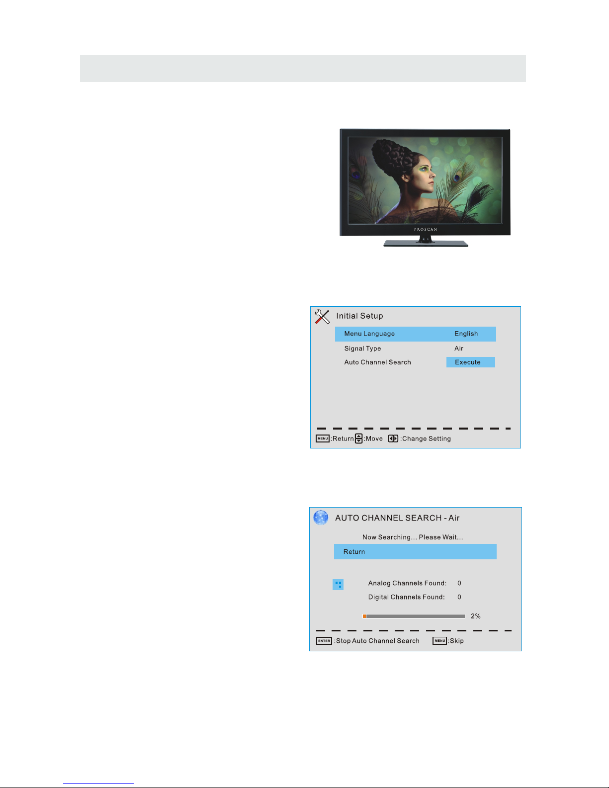
INITIAL SETUP
Wh en you tu rn on you r television set for
th e first time, be sure to place it on a solid
st able sur fa ce.
To avo id dang er, do not expose t he T V
to water, or a heat s ource
(e .g. la mp, ca ndle, ra diato r).
Do not obst ruct the ve ntilation grid
at t he rear and be sure to leave suffi cient
ga ps around the unit.
PUTTING THE UNIT ON A PROPER PLACE
TURNING THE UNIT ON FOR THE FIRST TIME
Af ter yo u have initially co nnected your TV
antenna or ca ble,
tu rn the television ON.
12
A screen will display asking you to run a
Initial Setup menu to search and receive
available local digital channels.
It is where you will select Menu Language
and choose your Signal Type between
Air and Cable.
After that , you can choose Auto Channel Search
and then it will search analog channels first,
then digital channels.
Before execute auto channel search, please
confirm your antenna type is Air or Cable.
Wrong setting of Signal Type maybe cause
finding no channel.
Page 16
13
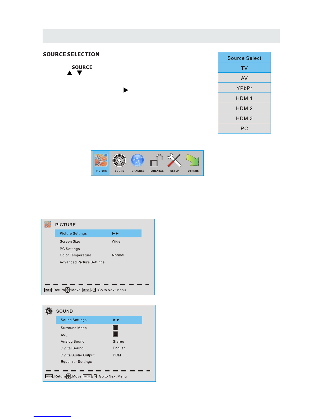
1. Press the butto n on the remote control.
2.
and select an y of them usi ng the butt on or
the button.
ource
Note:
Before watching please make sure all necessary
cables and devices are co nnect ed.
ENT ER
Us e or button to selec t the opt ionsthe
(T he screen will c hange to your de sired s ).
(TV,AV,YPbPr, HDMI1,HDMI2,HDMI3,PC)
Main MENU
Press MENU to display the main menu or return to the previous menu or close the main menu.
Press ◄/► to high light the desired menu icon, and press ENTER to select.
If no buttons are pressed, the menu will close automatically after about 10 seconds.
Main Menu Description
Picture Menu
Adjust your picture settings.
The operations are slightly different among
different source.
Sound Menu
Adjust the sound settings.
TV SETUP
Page 17
TV SETUP
14
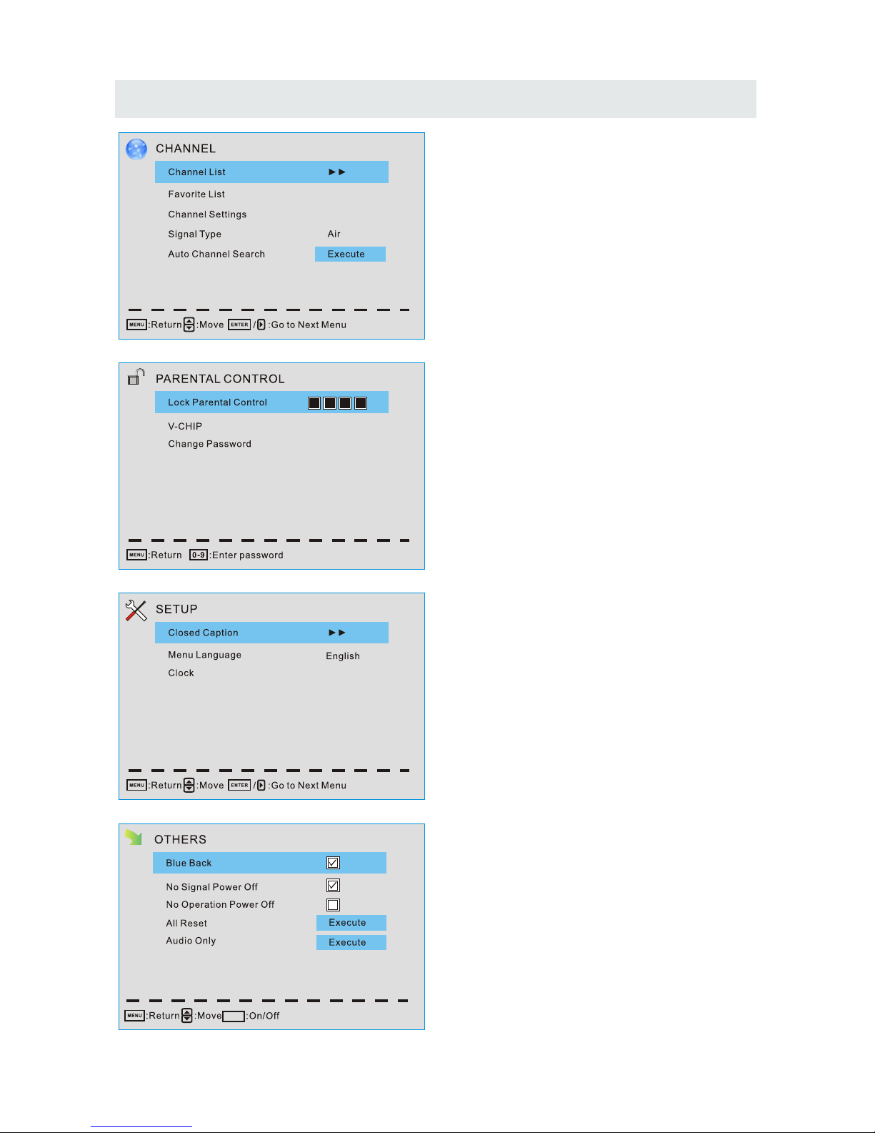
Channel Menu
Customize your channel settings.
Parental Control Menu
Set program rating control.
Setup Menu
Select closed caption options, language
and time.
Other Menu
Set the OSD blue background, whether auto
power off if no signal or no operation, clear
all user settings, etc.
ENTER
Page 18
TV SETUP
15
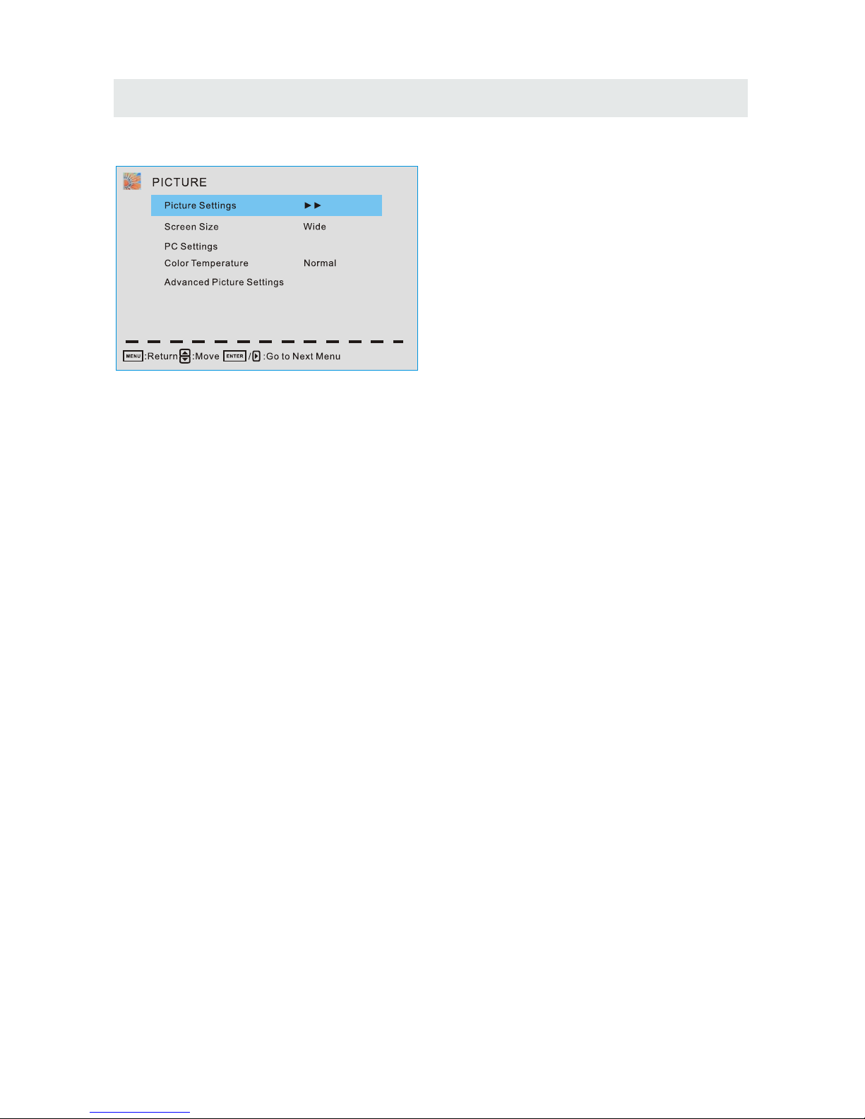
Picture Menu
Press ▲/▼ to highlight one of the following options, then press ENTER or ► to enter next
submenu to adjust it. Press EXIT to clear on-screen menu or MENU back to the previous
menu.
Picture Settings
Adjust the picture quality including brightness, contrast, color, tint, sharpness.
Screen Size
Press ◄/► to select the display aspect ratio till the picture is fit onto the screen.
The operations are different according to different input source.
PC Settings
The item is available only for PC DB15 input mode.
Color Temperature
Press ◄/► to select the color temperature that you feel comfortable.
Cool Gives white colors a blue tint.
Normal
Gives white colors a neutral tint.
Warm
Gives white colors a red tint.
Advanced Picture Settings
The Item is some special picture feature.
Page 19
TV SETUP
16
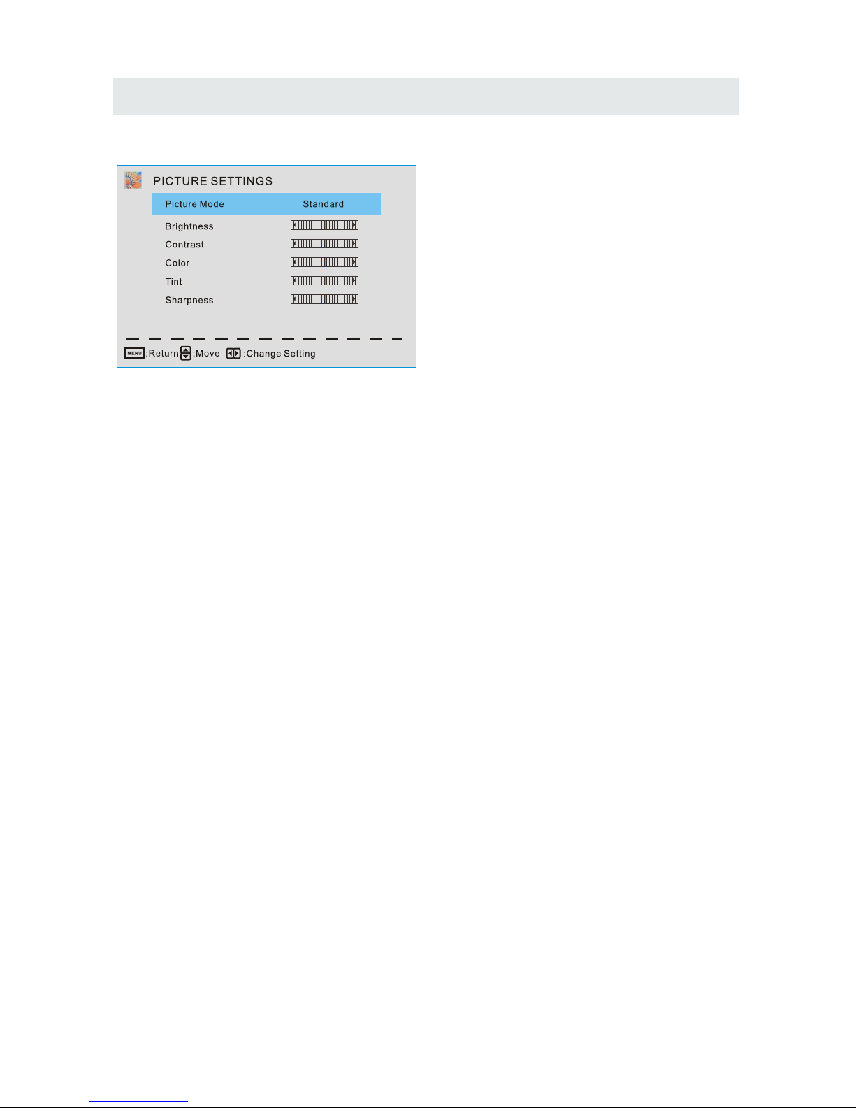
Picture Settings
When Picture Mode is set to User, the following setting can be manually adjusted.
Press PMODE shortcut button on the remote control to select picture mode directly.
Picture Mode
Highlight the item and Press ◄/► to select Standard/ Movie/ User/ Dynamic.
Standard Produces a highly defined image in a normally lit room.
Movie Produces a highly defined image in gentle lit room.
User Select to customize picture setting.
Dynamic Produces a highly defined image in a bright lit room.
Highlight the item and press ►, and a process bar appears, then press ◄/► to adjust the value.
Tint is available when analog TV or NTSC-system AV.
Press MENU to back the Picture Settings menu.
Brightness
Adjust darkness of black sections in the picture.
Contrast
Adjust the white level of the picture.
Color
Adjust the color intensity of the picture.
Tint
Adjust the hue( Red, Green, Blue) of the picture.
Sharpness
Object edges are enhanced for picture detail.
Page 20
TV SETUP
17
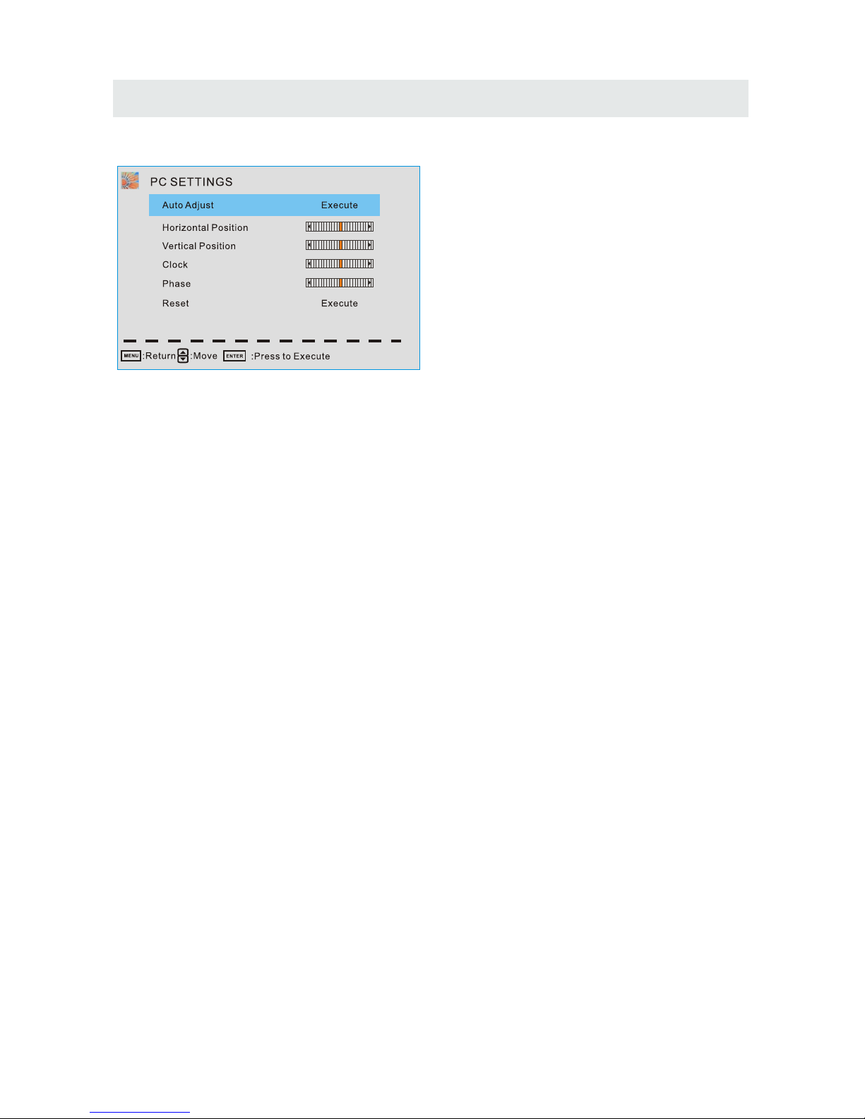
PC Settings
PC Settings Menu is aviliable only in PC DB15 mode.
Press ▲/▼ to highlight one of the following options, then press ENTER to select it.
Auto Adjust
Automatically adjust Clock, Phase, H-Position and V-position settings.
Horizontal Position
Shift the screen slightly to left or right.
Vertical Position
Shift the screen slightly up or down.
Clock
Adjust the DB 15 Picture signal sampling clock rate.
Phase
Adjust the DB 15 Picture signal sampling phase. It maybe affect the definition. Wrong value
maybe result the interference.
Reset
Reset the parameters of current menu to default value.
Page 21
TV SETUP
18
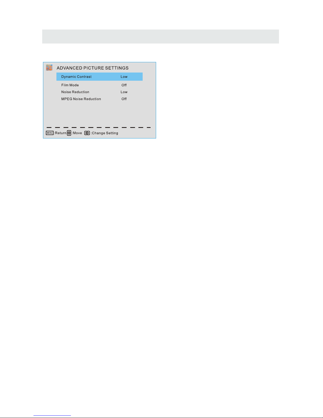
Advanced Picture Settings
Press ▲/▼ to highlight the item and press ENTER or ► to display the submenu as following.
Dynamic Contrast Off/ Low/ Medium/ High
The system will adjust the luminance curve by analyzing the picture content dynamically.
Film Mode Off/ On
For the 2:2 or :2 format signal of cinema, enable special pixel process to reduce the flick of
moving area.
Noise Reduction Off/ Low/ Medium/ High
You can clear up analog TV signal by reducing the dot noise. This feature is not available at
PC source.
MPEG Noise Reduction Off/ Low/ Medium/ High
Similar with the Noise Reduction, you can set to reduce the block noise.
Page 22
TV SETUP
19
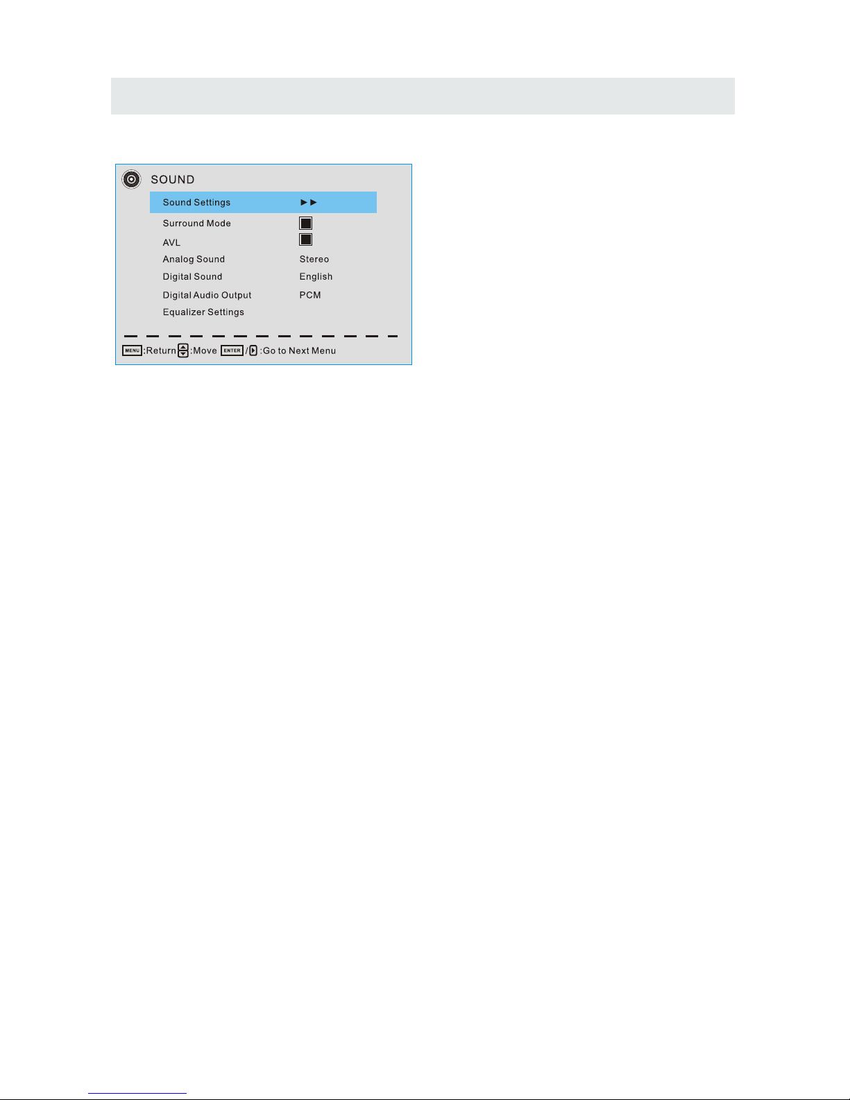
Sound Menu
Sound Settings
Set the sound mode, and Bass/ Treble/ Balance.
Surround Mode
Set to enjoy the virtual surround sound. Press ENTER to set or cancel.
AVL
Auto Volume Level. Press ENTER to set or cancel. When AVL is set on, it will limit the sound
being heard when sudden changes in volume occur during commercial breaks or channel
changes.
Usually be enabled at night.
Analog Sound
Available at analog TV channels, SAP/ Stereo/ Mono
Set the preferred sound track of analog channels. Stereo and SAP ecist on some channels.
Generally SAP is a second language sound or help the people with hearing impair.
Digital Sound
Available at digital TV channels, English/ French/ Spanish
Set the preferred sound track of digital channels, French and Spanish exist on some channels.
Digital Audio Output PCM/ Raw/ Off
Set the audio output type of coax or optical terminal. Raw means output the original format of
audio stream. PCM can be matched with most AV amplifiers.
Equalizer Settings
Adjust the curve of 7 bands equalizer.
Page 23
TV SETUP
20
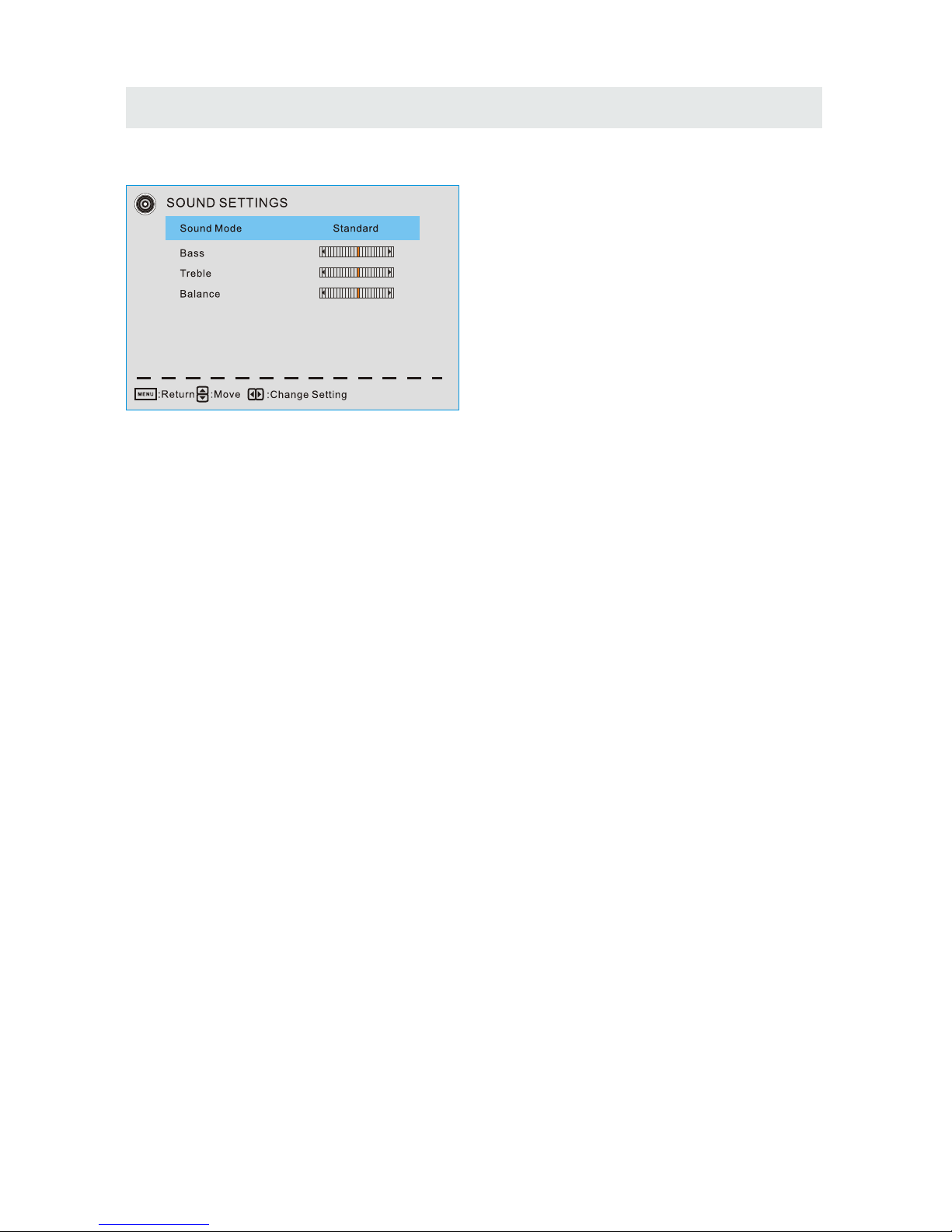
Sound Settings
Sound Mode Standard/ Soft/ User/ Dynamic
Only in User mode, the following items can be adjusted.
Bass
Adjust the low frequency band response.
Treble
Adjust the high frequency band response.
Balance
Adjust the level of sound coming from the left or right speaker.
Adjust the Bass/ Treble/ Balance
1.Set sound mode to User.
2.Highlight the item and press ► to display the submenu, the press ◄/► to adjust the value.
Page 24
TV SETUP
21
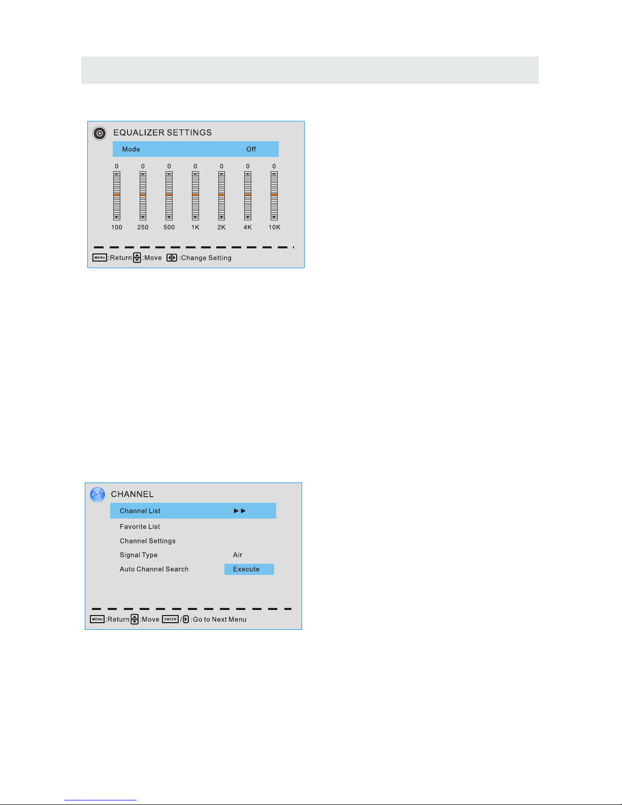
Equalizer Settings
Mode Off/ Rock/ Pop/ Jazz/ User( only in User mode, the following can be manually adjusted.)
Adjust Equalizer Settings
Based on your favorites about which frequency band need to be adjusted, make small
adjustment with certain frequency band at a time. Suggest NOT making too large changes.
1.Set mode to User.
2.Press ▼ to select the first( 100Hz) item, then press ◄/► to select the band to be turned.
3.Press ▲/▼ to adjust the value.
Channel Menu
Note: The menu is available only at TV source.
Page 25
TV SETUP
22
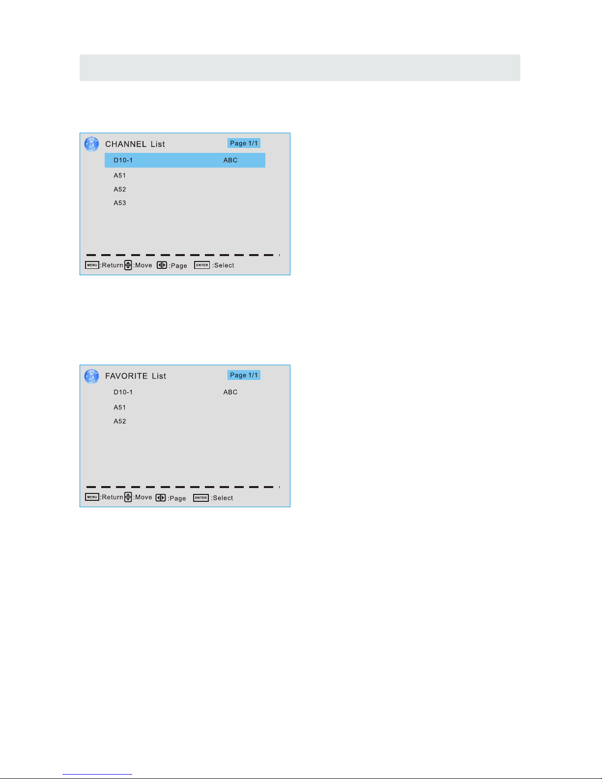
Channel List
You can view all the channels and choose one quickly.
“ABC”: Label of the Channel.
Press ▲/▼ to highlight a channel and press ENTER to view it.
Favorite List
All of you favorite channels are listed in this menu, and you can choose them quickly.
Channel Setting
Set the favorite channels, skipped channels, label of channels.
Signal Type
Set to Air or Cable according to your antenna source.
Page 26
TV SETUP
23
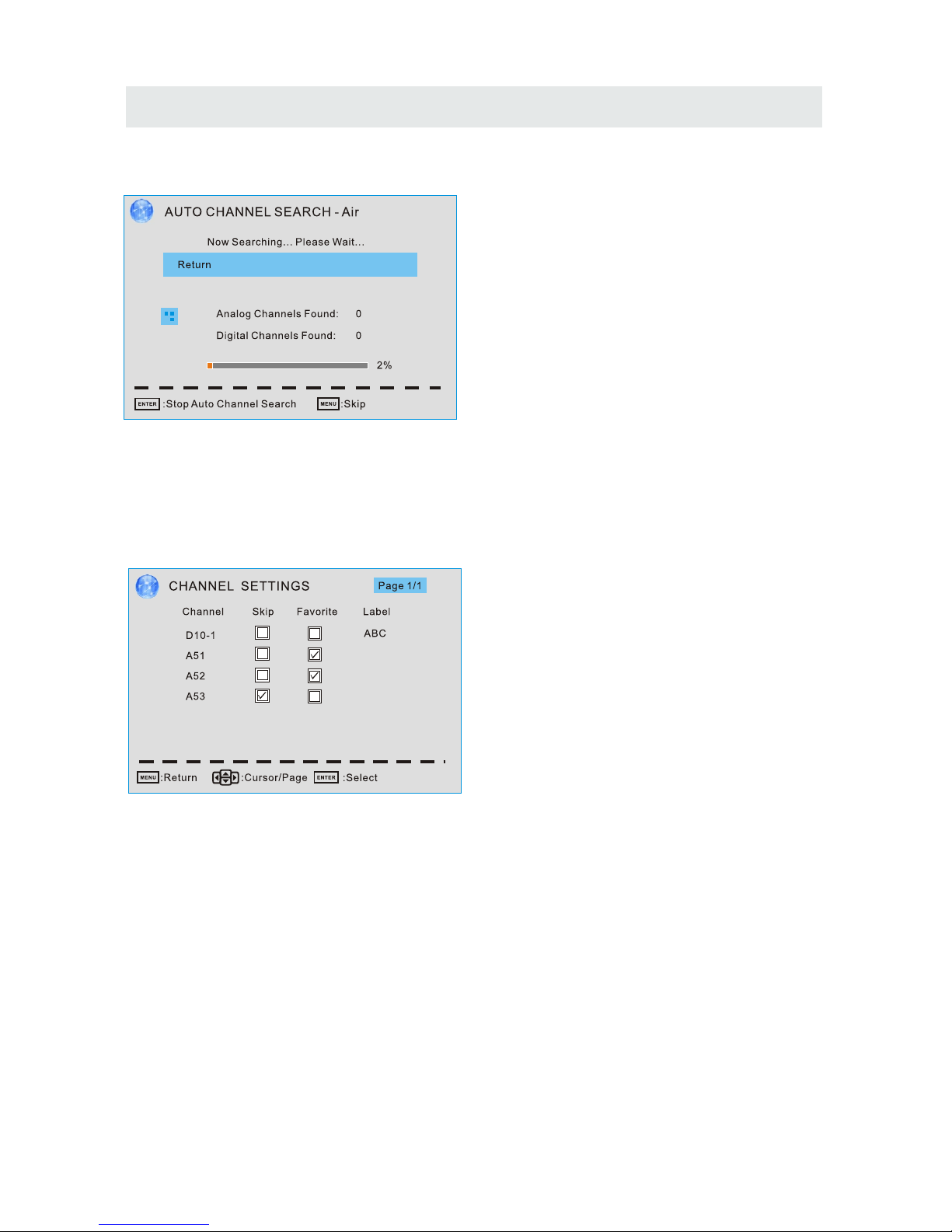
Auto Channel Search
Highlight and press ENTER to start the auto searching.
It will search analog channels first, then digital channels.
Before execute auto channel search, please confirm your antenna type is Air or Cable.
Wrong setting of Signal Type maybe cause finding no channel.
Channel Settings
Change the settings
Skip & Favorite
1.Press ▲/▼ to select the channel you want to set.
2.Press ◄/► to highlight corresponding item, and press ENTER to set or cancel.
Label
1. Press ▲/▼ to select the channel and ENTER to enter the edit state.
2. Press ▲/▼ to select the character, press ◄/►to move the cursor. Total seven letters.
Skip
Set the channel to be skipped when using
CH+/CH- to view channels.
Favorite
Set the channel to your favorite list.
Label
Rename label of the channel.
Page 27
TV SETUP
24
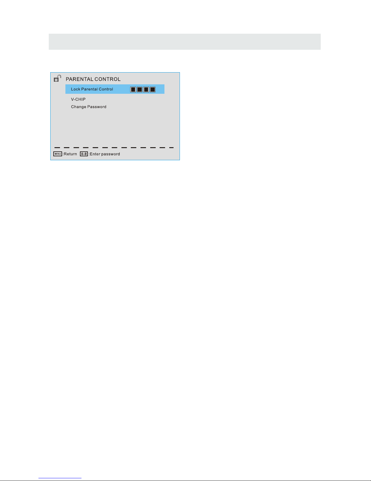
Parental Control
Note: The default user password is "0000", and if forget what you set, try"1470".
Lock Parental Control
The following items are only available if the password input is correct.
V-CHIP Include below settings:
US V-Chip
Rating system used at USA.
Canada V-Chip
Rating system used at Canada.
Block UnRated Show
Control whether lock the program that have not any valid rating flag.
Downloadable Rating
Control the RRT5 setting which are valid only at some digital cable channels.
Clear Downloadable Data
Select to clear the previous downloadable rating data.
Change Password
Enter a 4-digital number you want to set.
Page 28
TV SETUP
25
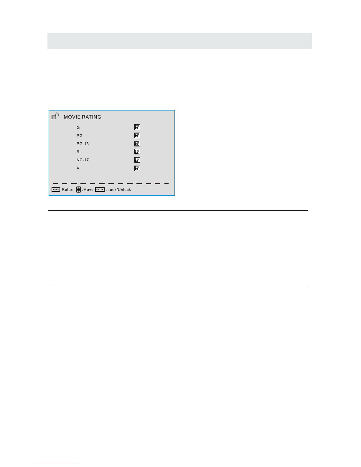
US V-CHIP
For the United States, the rating setting basically include the following options:
Movie Rating, TV Rating.
Moive Rating
This system defines the rating control which come from MPAA rules
Rating Define
G General audience. All ages admitted.
PG Parental guidance suggested . Some material may not be suitable for child ren.
PG-13 Parents strongly cautioned. Some material may be inappropriate for children
under 13.
R Restricted. Children under 17 require accompanying parent or adult guardian.
NC-17 No one 17 and under admitted
X Adult audience only.
Page 29
TV SETUP
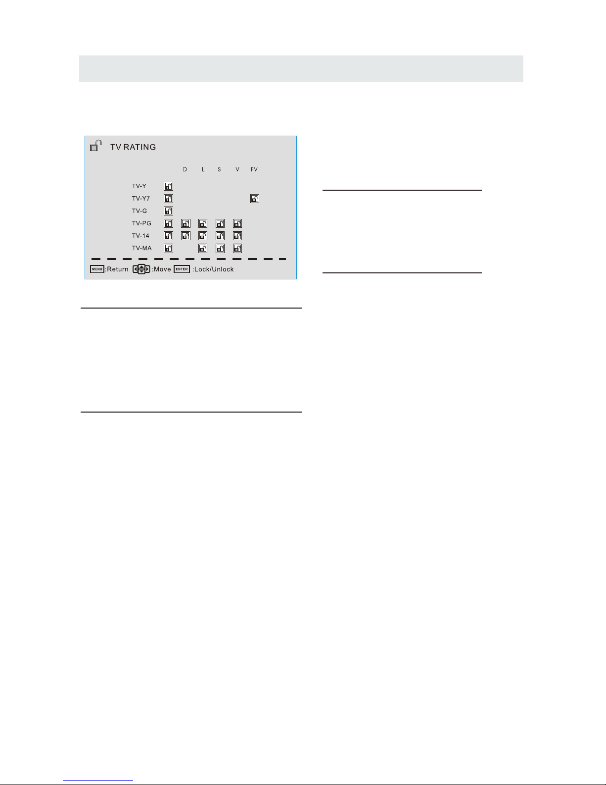
TV Rating
The TV rating compose of two aspects: age-based and content-based.
Age Define
TV-Y General audience
TV-Y7 Parental guidance suggested
TV-G Parents strongly cautioned
TV-PG Retricted
TV-14 No one 17 and under admitted
TV-MA Adult audience only
Content Define
FV Fantasy violence
D Suggestive dialogue
Strong language
L
S Sexual situations
V Violence
Note: The content ratings will increase depending on the level of the age-based rating. For
example, a program with a TV-PG V(violence) rating may contain moderate violence, while a
TV-14 V(violence)rating may contain intense violence. So locking a higher level option will
automatically cause locking the option that has more sensitive level.
26
Page 30
Canada V-CHIP
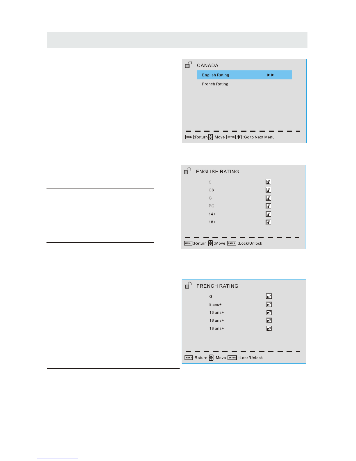
For Canada, the rating setting include the
following options: English rating, French Rating.
English Rating
These ratings are for programs which are using
English rating system.
Rating Defined as
C Children
C8+ Children 8 years and older
G General programming
PG Parental guidance
14+ Viewers 14 and older
18+ Adult programming
French Rating
These ratings are for programs which are using
French rating system.
Rating Defined as
G General
8 ans+ Not recommended for younger children
13 ans+ Not recommended for children under
age 13
16 ans+ Not recommended for ages under 16
18 ans+ This program is restricted to adults
27
TV SETUP
Page 31
TV SETUP
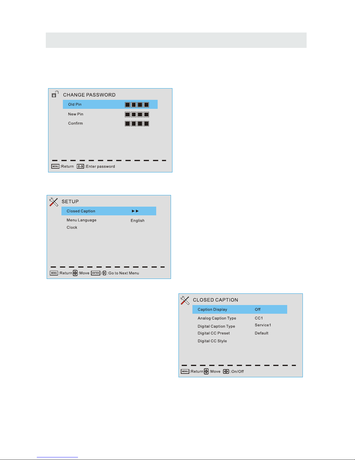
Change Password
At first you should enter the correct old password then enter new password twice.
If you lost your password, try to enter "1470".
Setup Menu
Closed Caption(CC)
Menu Language
Set the menu language. English/French/Spanish.
Clock
Set the Time Zone/ Auto Clock/ Setup Time/
Day of week/ Daylight Saving Time.
Caption Display
Display or hide the CC .
Analog Caption Type
Select from closed-caption modes for analog
programs.
Digital Caption Type
Applies only to digital channels with closed
caption.
Digital CC Preset Default/Custom
If set to Custom, Digital CC Style is available.
28
Page 32
TV SETUP
MENU
:Return :Move
:Change Setting
DIGITAL CC STYLE
CC Size
CC Font
CC Opacity
Text Color
CC Background Opacity
CC Background Color
Default
Default
Default
Default
Default
Default
CLOSED CAPTI ON
CC Size Small/Standard/Large/Default
CC Font Style0~7,Default
CC Opacity Default/Solid/Flashing/Translucent/Transparent/Default.
Text Color Black/White/Red/Green/Blue/Yellow/Magenta/Cyan/Default.
CC Background Opacity Solid/Flashing/Translucent/Transparent/Default.
CC Background Color Black/White/Red/Green/Blue/Yellow/Magenta/Cyan/Default.
Digital CC Style
This menu is valid only for digital closed caption of digital channels.
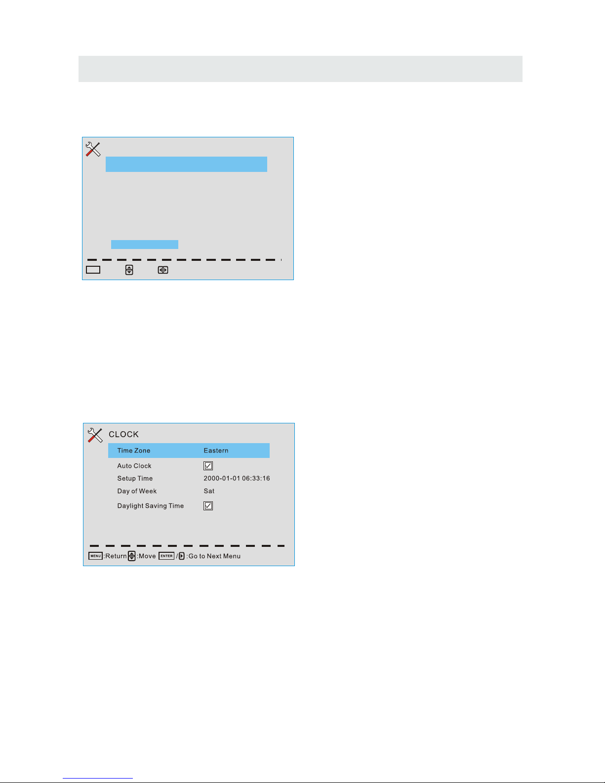
Clock
Time Zone Hawaii/Alaska/Pacific/Centra/
Mountain/Eastern/Samoa/Newfounland/Altantic
Set the time zone.
Auto Clock
If set it to ON , the TV will sync the local clock
according to the DTV broadcasting time
automatically. Otherwise you can set the time
manually.
Setup Time
Set Auto Clock to Off, then you can set the time manually .
Note: In the case of loss of power, the clock setting will be lost
Day of Week
The TV will calculate current day of week according to the time.
Daylight Saving Time
When Auto Clock set to ON, this item is available to enable daylight saving option or not.
29
Page 33
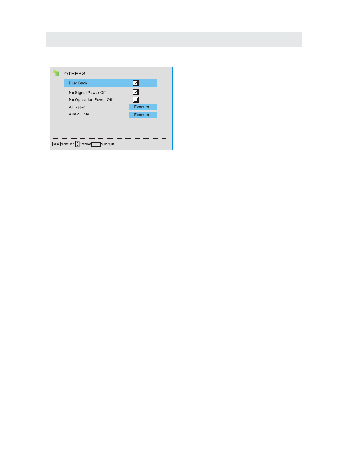
Others Menu
Blue Back
Set the screen background color blue or not when no valid signal input. When analog TV
input and has no signal, snow noise will display if this option is cleared.
No Signal Power Off
If it is set,TV will automatically enter standby after 10 minutes without signal input.
No Operation Power Off
If it is set, TV will automatically enter standby after 3 hours without any operation.
All Reset
When you highlight the item, the system will note you that"Attention! If [AlI Reset] was
executed,TV system is reset" , and if you are sure to reset, press ENTER to reset .
Audio Only
When you highlight the item, the system will note you that "Attention! Hold on power key 3
second to restore video", and if you are sure not need to view (backlight is turned off),
press ENTER to confirm. As the attention, if you want to wake up the video, please hold on
the power button for 3 seconds.
30
ENTER
TV SETUP
Page 34
DISPLAY MODE
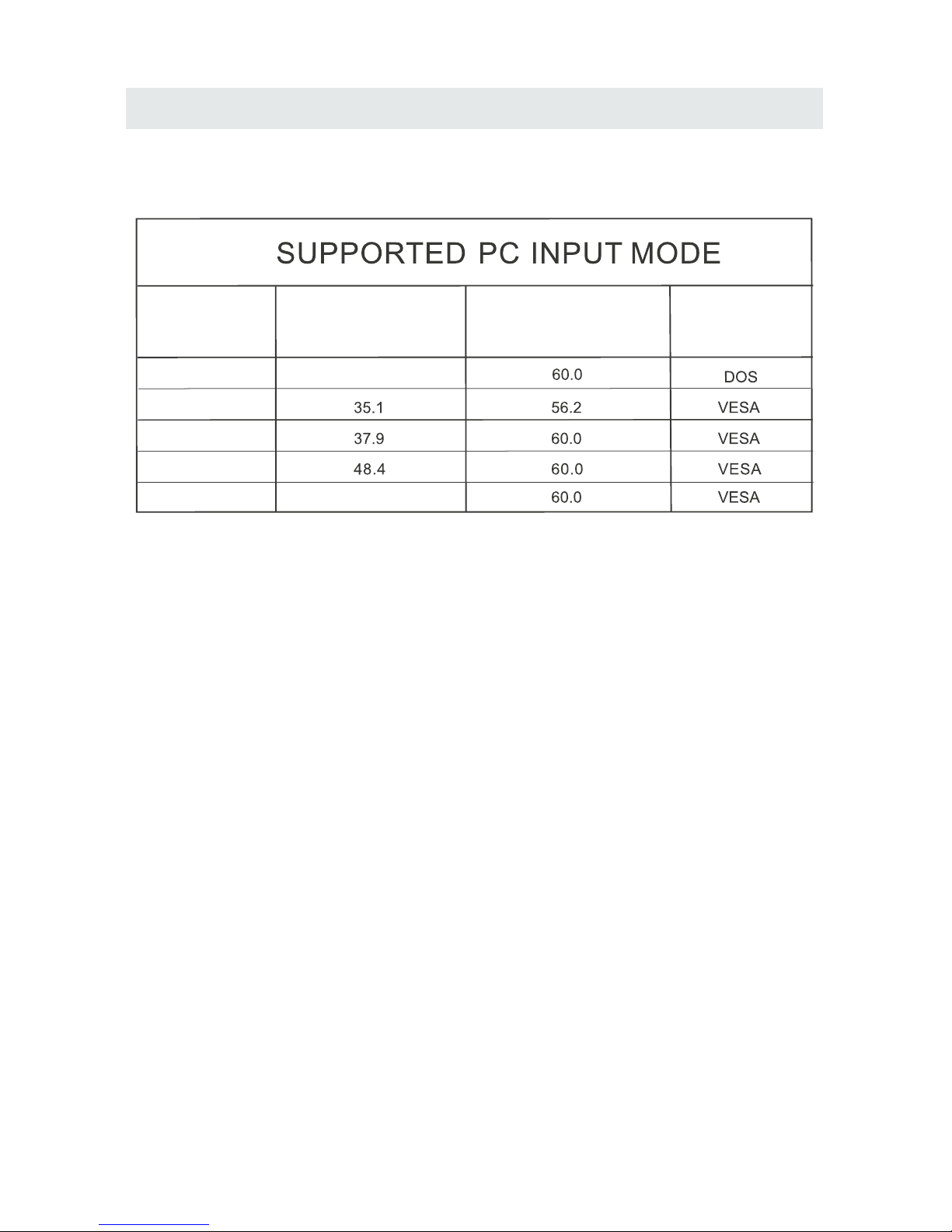
PC FORMATS
H i o aor z nt l
Sc ning F eq enan r u cy
Res l io
o ut n
(KHz)
Vert c l
i a
Sc n n e e
an i g Fr qu ncy
(Hz)
Format
640 480
00 6
008
00 6 0
8 0
024 681 7
31.5
X
X
X
X
NOTE:
This product does not support the display mode not listed above.
In order to achieve the best display effect, please select the above-listed
5 display modes input signal.
Because of the difference of display drivers output signal
(especially non-standard signal output), the display image may appear little
disturbance which can be adjusted on the PC menu.
To prolong this unit's service life, please set your computer to power management mode.
31
6.6 6
1920 x 1080
Page 35
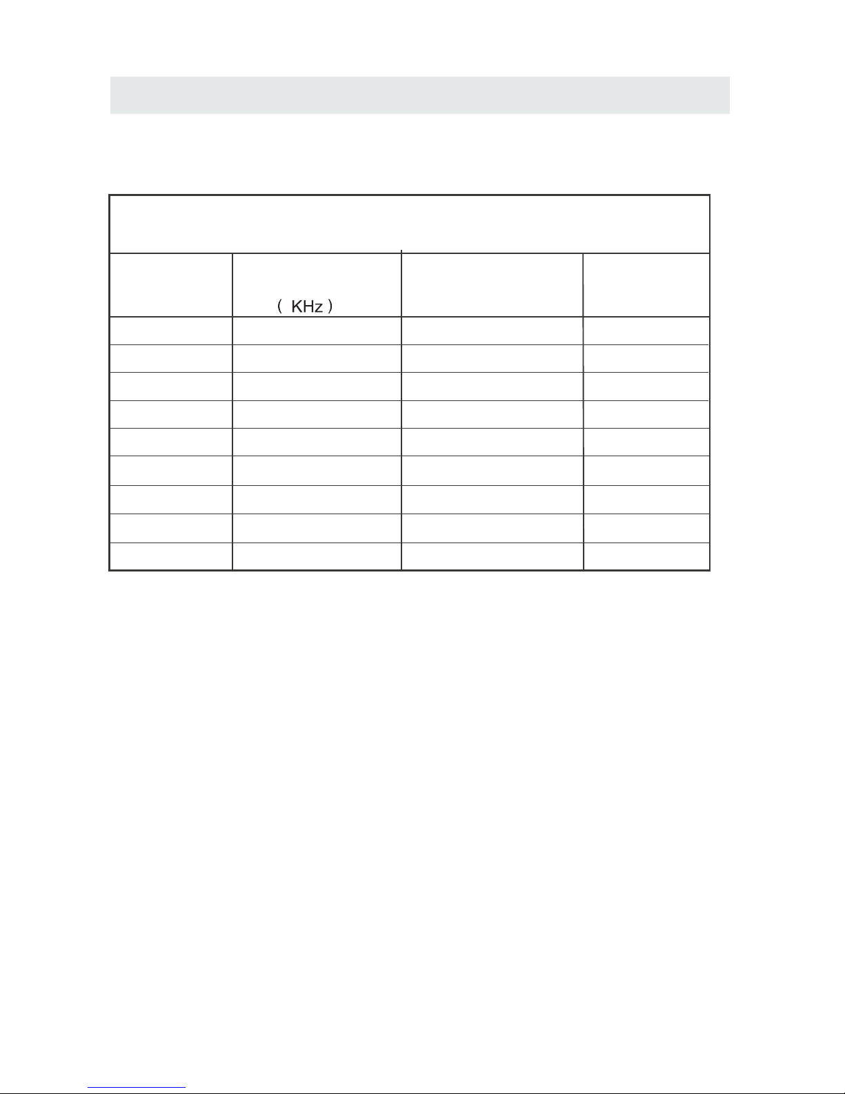
DISPLAY MODE
VIDEO FORMATS
SUPPORTED COMPONENT / HDMI INPUT MODE
Horizontal
Scanning Frequency
Vertical
Scanning Frequency
Format
(Hz)
720 480
720 480
1280 720
1280 720
1920 1080
31.47
15.734
37.5
45
31.25
33.75
59.94
59.94
50
60
50
60
480 p
480 i
1080 i
720 p
720 p
1080 i
e iR so
lut
on
X
X
X
X
The above listed formats are also related to the AV devices you are about to connect.
Before you connect this unit with others please read all instructions carefully and
make sure all necessary cables are connected.
.
This unit may be incompatible with some other formats which are not meet the
above conditions.
NOTE:
1920 1080
X
X
1920 1080
X
1920 1080
X
1080 p
1080 p
1920 1080
X
1080 p
50
60
24
27
56.25
67.50
32
Page 36
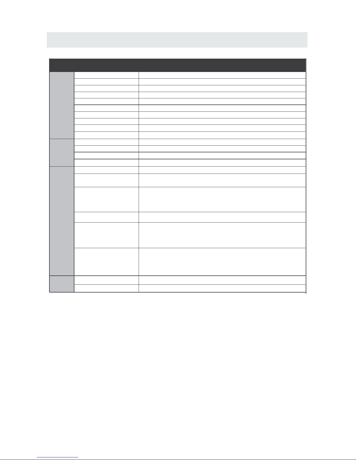
SPECIFICATION
42”LED TV
Panel Type LED Panel
42 inches
Diagonal Size
Screen Format 16 9:
Color System
ATSC/QAM/NTSC
Model Description
Panel
Resolution 1920 x1080
View Angle
Response Time
Contrast
Brightness
Maximum Color
360 nit
16.7M colors
Sound Output
RF Input 75 ohm external terminal
HDMI Input
Video 480i 480p 720p 1080i, 1080p.: , , ,
Audio Two channel linear PCM 32 44 1 and 48kHz 16 20 and 24 bits: , . , ,
PC RGB Input-
D sub 15pinG 0 7Vp p 75ohms: . - ,
B 0 7Vp p 75ohms: . - ,
R 0 7Vp p 75ohms: . - ,
Power Requirement
Input /
Output
Jacks
Systems
Power
Sound System
M
Audio System
MTS
L/R Speaker:10 W+ 10W
Composite Video Input
Component Y Pb Pr Input/
Sound Input
PC AUDIO: For PC RGB Audio input
500mV rms, Impedance: 20k ohms
RCA
Y:1.0 Vp-p, 75ohms, 0.3V negative sync
Pb:0.7Vp-p, 75ohms
Pr : 0.7Vp-p, 75ohms
100-240V~ 50/60Hz
178(H)/178(V)
68W
This manual is only for your reference.
Specifications are subject to update without prior notice.
1.0 Vp-p, 75ohms RCA
AV AUDIO: For CVBS Audio input
Component AUDIO: For Component Audio input
33
8 ms
Refresh Rate
60Hz
Rated power consumption
1400:1
Page 37

SYMPTOM CAUSE AND REMEDY( )
TV
Bad
Picture
(snow,
multiple
images
distortion,blurry)
No sound.
Black
and
White
picture.
No picture or sound.
Coloredp atches of
picture.
Panel function key does
not respond correctly.
• Check the location of the antenna and adjust it if necessary.
• Make sure the antenna cable is firmly connected.
• Make sure all input cables are firmly connected.
• Increase the volume.
• Check the PICTURE setting within the PICTURE menu.
• Make sure the unit is plugged in and turned on.
• Make sure that the ATV mode is selected.
• Try a new channel to check for possible station trouble.
• Make sure the antenna is connected properly.
• Increase the volume.
•
• Make sure all cables are firmly connected.
• Check for local interference.
• Make sure there are no unshielded electrical devices nearby
that are causing interference.
• Turn the TV off for 30 minutes, then try it again.
• Under the influence of electrostatic phenomenon, the product
may malfunction and require usertopowerreset.
• Unplug and re-plug the AC power cord.
TROUBLESHOOTING GUIDE
• Check to make sure the program you are watching is broadcast
in Color and not Black & White.
• Check
whether the mute function has been activated on the
Remote Control.
The display monitor's
panel goes hot.
• LED TV takes inside lighten phosphor. It may increase the
temperature of the screen in some occasions. It's not a defect.
Unusual dots
• Black dots and Bright points may appear on the LED screen.
This is a structural property of the LED panel and is not a defect.
Stripes on screen
• Adjust the impulse phase may decrease stripes. RGB in( )
The top of the monitor
• It may occur during long-time working. It's not a defect.
gets hot.
Make sure the antenna or audio/vid eo source device is
working properly.
Unable to select a
certain channel.
The channel may be skipped. Choose this channel by
directly selecting the buttons from the remote control.
•
Disorder display
at power on.
••This may be caused because of a very short int erval
between POWER OFF and ON.
Unplug the power and restart.
34
 Loading...