

Page 1

PLD3283C
32
Page 2

TV Base Stand assemble
4.3.Customizing theTIME Settings
4.4.Customizing the SETUP Settings
4.5.Customizing the Patental Settings
4.6.Customizing the TV Settings
20
21
24
27
Initial Setup
3.1. Initial Installation
3.2. Audio/Video Source Selection
3.3. DTV Mode Operations
17
17
17
PC Mode
30
31
33
SETTINGS
4.1.Customizing the PICTUERE Settings
4.2.Customizing the Audio Settings
18
18
19
Page 3

Page 4

Page 5

TV Base Stand assemble
3.Mounting on the wall
This unit is VESA-complian,and is designed to be wall-mounted
with a VESA-compliant 4"x10"(101.6mmx254mm)mounting kit
designde for flat-panel TVs(not supplied).Mount this unit according
to the instructions included in the monting kit. Length of screw should
not exceed 8 mm
NOTE
Remove the base stand before mounting the unit on the wall.
4"
10"
Four mounting holes
(size M4 screw)
Page 6

USB
(For Service)
R
Audioin
L
VIDEO
Pr
Pb
Y
RF
HDMI1 HDMI2 VGA PC AUDIOCOAXIAL
1. Headphones
2. Coaxial: Digtial audio output
3. HDMI
4. VGA: PC video input
5. PC AUDIO: Connect it to the
audio output terminal of PC
6. RF: Antenna connection
7. YPbPr: Connect to the YPbPr
video output terminal of DVD
8. Video: Video input
9. AUDIO IN R/L: Stereo audio input
10. USB Host port (For Service)
Page 7

sound from speakers
ASPECTSelectsthescreensize
UniversalRemote Code:08F7
(Universal Rmote Control is not included)
Page 8

adaptor
USB
(For Service)
USB
(For Service)
Audioin
VIDEO
Pr
Pb
RF
R
L
Y
Audioin
VIDEO
USB
R
L
Pr
Pb
Y
RF
(For Service)
Audioin
VIDEO
Pr
Pb
RF
R
L
Y
Page 9

HDMI1 HDMI2 VGA PC AUDIOCOAXIAL
HDMI1 HDMI2 VGA PC AUDIOCOAXIAL
Note:Coaxial output
HDMI1 HDMI2 VGA PC AUDIOCOAXIAL
HDMI1 HDMI2 VGA PC AUDIOCOAXIAL
Page 10

3. Initial Setup
3.1. Initial Installation
The first time the unit is turned on or anytime the system is restored to
the defaulted settings, the Initial Installation wizard will be displayed on the
screen.
Conect the antenna cable to the RF connector at the connections panel
and follow the steps displayed on the screen to set up the system basic
settings (Language, Cable, etc.) and start an auto search of TV channels.
3.2. Audio/Video Source Selection
Turn on the TV by pressing the POWER button on TV
or on the remote control, press SOURCE and use the
direction buttons
depending on the equipment you have connected (AV,
HDMI, VGA) or choose TV to enter these mode.
/ to select the desired source
Customizing the PICTURE
4.1.
Select TV source for example. (Press SOURCE bu on to select TV mode)
1. Press the POWER bu
2. Press the MENU bu
to select the PICTURE.
3. Use the Ÿ/ź bu
change the se
The PICTURE menu includes the following
on to turn the LED TV on.
on on the remote control to display the Main menu, and use the Ż/Ź
ons to highlight an individual PICTURE ,use theŻ/Ź to
and press the MENU to exit the menu.
:
3.3. DTT Mode Operations
Use CH+ or CH- buttons to tune the desired channel, or enter the channel
number directly using the numeric keypad. Press OK to display on screen the
list of TV and radio channels (press the
/ buttons to sort by group and
show only the DTV, the analog TV channels, Radio channels, etc.).
Use MTS button to select the audio language broadcasting, CC button to
show or hide subtitles on screen and FAV button to see a list of your favorite
channels.
4. SETTINGS
17
Picture Mode
Contrast
Brightness Control the overall brightness of the picture.
Color Control the color.
Tint Controls the nt.
Sharpness
Color Temp. Cycles among color modes: Normal, Cool.Warm,
Cycle among picture display modes: Standard, Dynamic, Mild, user.
Control the diīerence between the brightness and darkest regions of the
picture.
Increase this se ng to see crisp edges in the picture; decrease it for so
edges.
18
Page 11
Customizing the Audio
4.2.
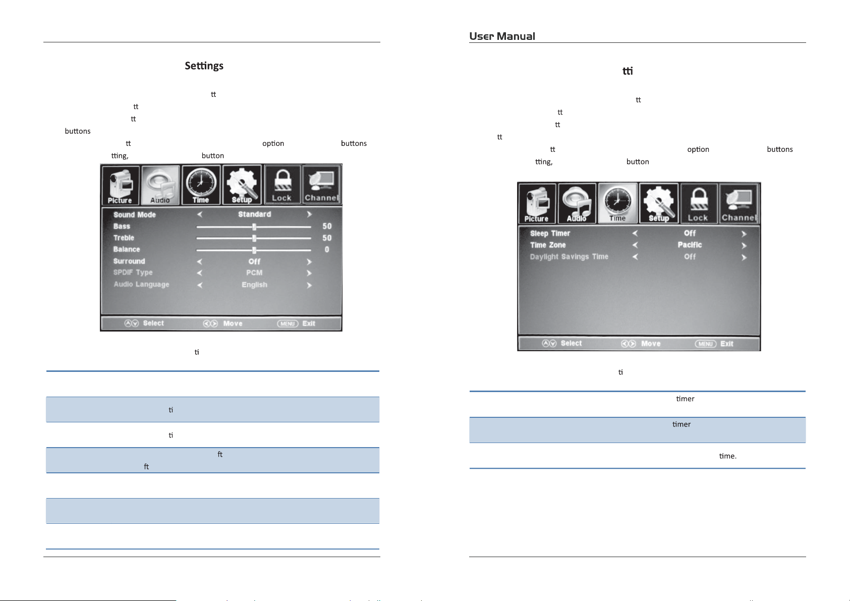
Customizing the TIMER Se ngs
4.3.
Select TV source for example. (Press SOURCE bu on to select TV mode)
1. Press the POWER bu
2. Press the MENU bu
to select the AUDIO.
3. Use the Ÿ/ź bu
change the se
The AUDIO menu includes the following op
Sound Mode Allow you to select among: Standard, Music, Movie and User.
Bass Control the rela ve intensity of lower pitched sounds.
Treble Control the rela ve intensity of higher pitched sounds.
on to turn the LED TV on.
on on the remote control to display the Main menu, and use the Ż/Ź
ons to highlight an individual AUDIO ,usetheŻ/Ź to
and press the MENU to exit the menu.
ons:
Select TV source for example. (Press SOURCE bu on to select TV mode)
1. Press the POWER bu
2. Press the MENU bu
bu
ons to select the TIMER.
3. Use the Ÿ/ź bu
change the se
The TIMER menu includes the following op ons:
Sleep Timer
Time Zone
on to turn the LED TV on.
on on the remote control to display the Main menu, and use the Ż/Ź
ons to highlight an individual TIMER ,usetheŻ/Ź to
and press the MENU to exit.
Allow you to set up the sleep
30min,45min, 60min, 90min, 120min, 180min, 240min and oī.
Allow you to set up the sleep among: PaciĮc, Alaska, Hawaii,
Eastern, Central and Mountain.
among: 5min, 10min, 15min,
Balance
Surround Allow you to select between Oī and On.
SPDIF Type Allow you to select between PCM and RAW.
Audio Language Allow you to select audio language among: English, French and Spanish.
To adjust the balance of the le and right sound track, or turn oī the volume
of the le and right sound track.
19
Daylight Saving Time Allow you to turn on or oī the daylight saving
20
Page 12

Customizing the SETUP Se ngs
4.4.
Select TV source for example. (Press SOUCE bu on to select TV mode)
1. Press the POWER bu
2. Press the MENU bu
bu
ons to select the SETUP.
3. Use the Ÿ/ź bu
change the se
The TIMER menu includes the following op
Menu Language Allow you to select menu language among: English, Français and Español.
Transparency Allow you to turn on or oī the transparency
Zoom Mode
Noise Re on
Advance
on to turn the LED TV on.
on on the remote control to display the Main menu, and use the Ż/Ź
ons to highlight an individual SETUP ,use theŻ/Ź to
and press the MENU to exit.
ons:
Allow you to select the zoom mode among:
Normal.
Allow you to select the noise re on mode among: Middle, Strong,
KītĞĂŬ
Input PC signal Įrst, then press SOURCE bu on to select VGA mode, press Ź
bu on to conĮrm.
CinemaWide, andZoom,
Close Cap on
H-Posi on Allow you to use the Ż/Ź bu ons to adjust the H Posi on.
V-Posi on Allow you to use the Ż/Ź bu ons to adjust the V Posi on.
Clock Allow you to prolong the image.
Phase Allow you to adjust the de
Auto Select “Auto” and press the Ź bu on, the unit will
automa adjust all items to achieve a best eīect.
Use the ź bu on to highlight the Close n item, then press the Ź
bu on to enter into the following menu.
21
CC Mode Allow you to select the CC Mode among: OnOī, and CC
on Mute.
Basic Allow you to select the basic sel on among: CC1, CC2,
CC3, CC4, Text1, Text2, Text3 and Text4.
Advanced Allow you to select the advanced sel on among:
Service1, Service2, Service3, Service4, Service 5 and
Service6.
Op Use the ź bu on to highlight the “Op on” item, then
press the Ź bu on to enter into the following menu.
22
Page 13

Customizing the LOCK Se ngs
4.5.
Select TV source for example. (Press SOURCE bu on to select TV mode)
1. Press the POWER bu
2. Press the MENU bu
bu
ons to select the LOCK.
3. Use the ź bu
password. A
to exit.
NOTE: The factory password is 0000. The supervision password is 8899.
on to turn the LED TV on.
on on the remote control to display the Main menu, and use the Ż/Ź
on to highlight “Enter Password” item, use the numeric keys to input 4-digital
er you that, the screen will display the junior menu. A er ngs, press menu
Use the Ÿ/ź bu ons to highlight the desired item, and
use the Ż/Ź bu
XVS To turn on or oī the XVS fun
ons to select.
on.
Restore Default Restore all se ngs in SETUP menu to factory se ngs.
4-digitalpassword
The LOCK menu includes the following op ons:
Change Password
Use the ź bu
Ź bu
Input the new 4-digital password and input it again to conĮrm.
on to select the “Change Password” item, then press the
on to enter into the following menu.
Input
23
System Lock
Allow you to turn on or oī the system lock.
If you turn oī the system lock, then the following items (US, Canada, RRT
Se ng and Reset RRT) will unable to use.
24
Page 14

US
Use the ź bu on to highlight the “US” item, then press the Ź bu nto
enter into the following menu.
TV Use the ź bu on to highlight the “ TV” item, then press
Ź bu on to enter into the following menu.
Use the Ÿ/ź bu ons to select the desired ra ng and
press the Ź bu on to block or unblock ra ng.
MPAA The Movie ra ng (MPAA) is used for original movies rated
by the Mo Picture Associa on (MPAA) as broadcasted
on cable TV and not edited for television.
Use the Ÿ/ź bu ons to select N/A, G, PG, PG-13, R,
NC-17 or X.
RATING DESCRIPTION
General Audiences. Movie is appropriate for
G
all ages.
Parental Guidance Suggested. May contain
PG
material not suited for younger viewers
Contains content that may not be
PG-13
appropriate for viewers under the age of 13.
Restricted. Contains adult content, no one
R
under 17 admi d without parent.
NC-17 No one 17 and under admi
X Adults only.
Canada
Use theź bu on to highlight the “Canada” item, then press Ź bu on to
enter into the following menu.
Canada Eng Use the Ż/Ź bu ons to select among: E, C, C8+, G,
PG, 14+ and 18+.
Canada Fre Use the Ż/Ź bu ons to select among: E, G, 8ans+,
13ans+, 16ans+ and 18ans+.
RRT Se ng
Reset RRT Allow you to reset the RRT se ng.
2
22526
Page 15

Customizing the CHANNEL Se ngs
4.6.
Select TV source for example. (Press SOUCE bu on to select TV mode)
1. Press the POWER bu
2. Press the MENU bu
bu
ons to select the CHANNEL.
3. Use the Ÿ/ź bu
change the se
The CHANNEL menu includes the following
Air/Cable
Auto Scan
on to turn the LED TV on.
on on the remote control to display the Main menu, and use the Ż/Ź
ons to highlight an individual CHANNEL , use the Ż/Ź to
and press the MENU to exit.
:
Allows you to select antenna between Air and Cable.
If you select “Cable”, the following items (Favorite, Show/Hide, Channel
., Channel Label and DTV Signal) are unable to use.
NO
Use the ź bu on to highlight the “Auto Scan” item, then press Ź bu on
to enter into the following menu.
Favorite
The receivable channels will be stored automa cally.
When searching channels, press MENU to stop.
If you select “Cable” as input signal in Antenna item, allows you to select
Cable System among: Auto, STD, IRC and HRC.
Use the ź bu on to highlight the “Start to Scan”, then press the Ź
bu on to search the channels automa cally.
The receivable channels will be stored automa cally.
When searching channels, press MENU to stop.
Allow you t add these channels which you desired as the favorite
channels. Use the Ÿ/ź bu ons to highlight the “Favorite” item, then
press the Ź bu on to enter into the following menu.
If you select “Air” as input signal in Antenna item, you can press the Ź
bu on to search the channels automa cally.
27
Show/Hide
Use the Ÿ/ź bu ons to highlight the desired item, then press OK
bu on to add or remove the highlighted channel as favorite.
Allow you to show or hide the channels.
Use the Ÿ/ź bu ons to highlight the “Show/Hide” item, then press the
Ź bu on to enter into the following menu.
28
Page 16

Use the Ÿ/ź bu ons to highlight the desired item, then press OK
bu on to show or hide the highlighted channel.
Channel No. Display the number of current channel.
Channel Label Display the lable of current channel.
5. PC Mode
Se ng up your PC so ware (based on Windows XP)
The W indows display-se ngs for a typical computer are shown below. But the actual screen on
your PC will probably be diīerent, depending upon your par
cular video card. But even if your actual screen looks diīerent, the same, basic set-up
par
informa
on will apply in almost all cases.
cular version of W indows and your
DTV Signal Display the quality of current DTV signal.
922
1. First, click on “Control Panel” on the W indows start menu.
2. When the control panel window appears, click on “Appearance and Themes” and a display
dialog-box will appear.
3. When the control panel window appears, click on “Display” and a display dialog-box will
appear.
4. Navigate to the “Se
Op 1360×768.
cal-frequency on exists on your display se ngs dialog box, the correct value is “60Hz”.
If a ver
Otherwise, just click “Enter” and exit the dialog bo
Res n
720x400 31.47 70 DOS
640x480 37.9 60 VGA
800x600 37.9 60 SVGA
1024x768 48.4 60 XVGA
1366x768 64 60 SXVGA
ng” tab on the display dialog-box. The correct size se ng (res
x.
Horizontal
Frequency (KHz)
Frequency (Hz)
Standard Mode
Page 17

6
TV
TV
TV
Page 18

7
PLD3283C
1366 x 768
70W
AC 100-230V~, 50/60Hz
x 2
USB(For service)
and
 Loading...