


Model:PLCDV3213A

CONTENTS
15
17
19
20
23
26
27
1
2
2
3
3
6
7
3
4
8
9
8
8
9
9
10
10
4
6
6
7
12
13
13
13
SAFETY
PRECAUTION
IMPORTANT
SAFETY
INSTRUCTION
ACCESSORIES
GETTING
STARTED
5
CONTROL
REFERENCE
GUIDE
WALL MOUNT
INSTALLATION
INITIAL SETUP
TV SETUP
CONNECTIONS
Remote Control
Front View
Back View
Side View
Antenna Connection
AV Connection
Y Pb Pr Connection
HDMI Connection
VGA Connection
Headphone Connection
Power Cord Connection
Coax(SPDIF) Connection
Putting The Unit On A Proper Place
Turning The Unit On For The First Time
Source Selection
Picture Menu
Audio Menu
Time Menu
Setup Menu
LOCK(Parental) Menu
TV(CHANNEL) Menu
Zoom Function (For DVD)
1
English
10
11

CONTENTS
28
11
10
12
14
40
15
16
29
32
34
35
38
38
41
42
DISC
FORMA TS
CD / DVD
OPERA TION
CUSTO MIZING
THE DVD
FUNCT ION
SETTI NGS
DISPL AY
MODE
SPECI FICATION
TROUB LESHOOT ING
GUIDE
Basic Operations
Special Functions
Mp3 / JPEG Playback
PC Formats
Video Formats
DVD Symptom
TV Symptom
SAFETY CLASS :This is an IEC safety class I product
and it must be grounded for safety.
DVD Menu
13
MAINTENANCE
37
*
SAFETY PRECAUTION
CAUTION
•
•
•
WAR NING:
PLACEMENT INFORMATION
SAFE TY INFORMATION
CONDENSATION INFORM ATION
RATING PL ATE LOCATION
FCC STATEMEN TS
CLASS 1 LASER
PRODUCT
WARNING:
CAUT IO N MARKING W AS LOCATE D AT T HE REAR
OF THE A PP ARATUS.
WARNING:TO REDUCE THE RISK OF ELECTRIC
SHOCK,DO NOT REMOVE COVER(OR BACK)
NO USER SERVICEABLE PARTS INSIDE.
REFER SERVICING TO QUALIFIED SERVICE
PERSONNEL.
The lightning flash with arrowhead symbol,
within an equilateral triangle,is intended to
alert the user to the presence of uninsulated
“dangerous voltage”within the product's enclosure
that may beof sufficient magnitude to constitute a
risk of electric shock to persons.
The exclamation point within an equilateral
Triangle is intended to alert the user to
The presence of important operating and
maintenance (servicing) instructions in the literature
accompanying the appliance.
CAUTION
INVISIBLE LASER RADIATION WHEN
OPEN AND INTERLOCKS DEFEATED
AVOID EXPOSURE TO BEAM
This product
Contains a low
power laser device.
DANG ER O F EXPLOSI ON I F BATTERY I S
INCO RR ECTLY REP LA CED. REPL ACE ONLY
WITH T HE S AME OR EQUI VA LENT TYPE .
USE OF C ON TROLS OR AD JU STMENTS O R
PERF OR MANCE OF PR OC EDURES OT HE R
THAN T HO SE SPECIF IE D MAY RESUL T IN
HAZA RD OUS RADIA TI ON EXPOSU RE .
•
•
TO RED UC E THE RISK OF F IR E OR ELECTR IC
SHOC K, D O NOT EXPOS E TH IS APPLIA NC E TO
RAIN O R MO ISTURE.
TO REV EN T FIRE OR SHO CK H AZARD, DO N OT
EXPO SE T HIS UNIT TO R AI N OR MOISTU RE . DO
NOT PL AC E OBJECTS F IL LED WITH LI QU IDS ON
OR NEA R TH IS UNIT.
SHOU LD A NY TROUBL E OC CUR, DISC ON NECT
THE AC P OW ER CORD AND R EF ER SERVIC IN G
TO A QUA LI FIED TECH NI CIAN.
Do not u se t his unit in p la ces that ar e ex treme ly
hot, c ol d, dusty or h um id.
Do not r es trict the a ir flow of thi s un it by pla ci ng it
some wh ere with po or a irflo w, b y coverin g it w ith
a clot h, b y placing i t on b edding or c arpetin g.
When c on necting o r di sconn ec ting the AC p ow er
cord , gr ip the plug a nd n ot the cord i tself. Pu ll ing
the co rd m ay damage i t an d create a ha zard.
When y ou a re not goin g to u se the unit f or a l ong
peri od o f time, dis co nnect the A C power cor d.
When l ef t in a heated r oo m where it is w ar m and
damp , wa ter dropl et s or conden sation ma y fo rm
insi de t he equipm en t. When the re is conde ns ation
insi de t he unit, th e un it may not fu nc tion no rm ally.
Let th e un it stand fo r 1- 2 hours bef or e turni ng t he
powe r on o r gradual ly heat the r oo m and let the
unit d ry b efore use .
The ra ti ng plate is l oc ated on the r ea r of the un it .
NOTE : Th is unit has b ee n tested an d fo und to comp ly
with t he l imits for a C la ss B digita l de vice, pur suant
to Par t 15 o f the FCC Rul es . These lim it s are des ig ned
to pro vi de reason ab le prot ec tion agai ns t harmful
inte rf erence in a r es identia l install at ion.
This u ni t generat es , uses and ca n radiate r ad io
freq ue ncy energ y an d, if not ins ta lled an d us ed in
acco rd ance with t he i nstruct ions, may c au se harmfu l
inte rf erence to r ad io commun ication . Ho wever, th er e
is no gu ar antee tha t in terfere nc e will no t oc cur in a
part ic ular inst al lation. I f th is unit d oe s cause har mf ul
inte rf erence to r ad io or telev ision rec ep tion, whi ch
can be d et ermined b y tu rning the u nit off and o n, t he
user i s en courage d to t ry to corre ct the inte rf erence
by one o r mo re of the fol lo wing meas ures:
- Reor ie nt or reloc at e the recei ving ante nn a.
- Incr ea se the sepa ra tion betw een the uni t an d
rece iv er.
-Con ne ct the unit i nt o an outlet o n a ci rcuit d if ferent
from t ha t to which th e re ceiver is c on necte d.
- Cons ul t the deale r or a n exper ie nced radi o/ TV
tech ni cian for he lp .
Chan ges or mo dific at ions to t his
unit n ot expr essly a pp roved b y the par ty respon sible
for co mplia nce cou ld v oid the u ser aut hority
to ope rate th e unit.
•
•
•
•
•
1

IMPORTANT SAFETY INSTRUCTIONS
1)Rea d th ese instr uctions .
2)Kee p th ese instr uctions .
3)Hee d al l warning s.
4)Fol lo w all instr uctions .
5)Do no t us e this appa ratus nea r wa ter.
6)Cle an o nly with a dr y cloth.
7)Do no t bl ock any ven ti latio n op enings.
Inst al l in accord ance with t he
manu fa cturer' s instruc ti ons.
8)Do no t in stall nea r any heat so ur ces such
as rad ia tors, hea t re gisters , stoves, o r
othe r ap paratus ( In cludi ng a mplifie rs ) that
prod uc e heat.
9)Do no t de fect the sa fe ty purpos e of the
pola ri zed or grou nding-t yp e plug.
A pola ri zed plug ha s two blade s wi th one
wide r th an the othe r.
A grou nd ingtype p lug has two b la des
and a th ir d groundi ng prong.
The wi de b lade or the t hi rd pron g is
prov id ed for your s af ety.
If the p ro vided plu g does not fi t in to your
wall o ut let, cons ul t an electr ician for
repl ac ement of th e ob solet e ou tlet.
10)Pr ot ect the pow er cord fro m be ing walke d on
or pin ch ed partic ularly at p lu gs, conve ni ence
rece pt acles, an d th e point whe re they exi t
from t he a pparatu s.
11)On ly u se attach me nts / acces sories sp ec ified
by the m an ufactur er .
12)Us e on ly with the c ar t, stand,
trip od , bracket , or t able
spec if ied by the ma nu facture r,
or sol d wi th the appa ra tus.
When a c ar t is used, us e ca ution whe n
movi ng t he cart / app ar atus comb ination t o
avoi d in jury from t ip -over .
13)Un pl ug this app aratus du ri ng lightn in g
Stor ms o r when unus ed f or long p er iods of
time .
14)Re fe r all servi cing to qua li fied serv ic e
pers on nel. Serv icing is re qu ired when t he
appa ra tushas be en damage d in a ny way,
such a s th e power cor d or p lug is da ma ged,
liqu id h as been spi lled or obj ec ts have fal le n
into t he a pparatu s, t he appara tus has bee n
expo se d to rain or mo is ture, doe s not opera te
norm al ly, or has be en droppe d.
15)To p re vent elec tr ic shoc k, e nsure the g ro unding
pin on t he A C cord powe r plug is sec ur ely
conn ec ted.
2
ACCESSORIES
Please check and identify the supplied accessories.
.. .. ..... ..... ..... ..... ..... .. ..... ..... ..... ..... ..... .. ... .. ..... ..... ..... ..... ..... .. ..... ..... ..... ... ....... ..
.. .. ..... ..... ..... ..... ..... .. ..... ..... ..... ..... ..... .. ... .. ..... ..... ..... ..... ..... .. ..... ..... ..... ..... ..
.. .. ..... ..... ..... ..... ..... .. ..... ..... ..... ..... ..... .. ... .. ..... ..... ..... ..... ..... .. ..... ..... ..... ..... ...
GETTING STARTED
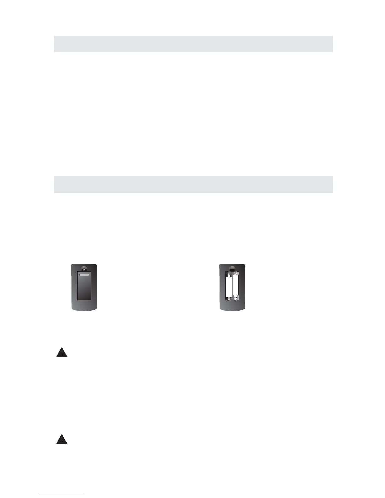
USIN G THE REM OTE CONTROL
TO INSTALL THE BATTERIES
BATTERY REPL ACEMENT
CAUTION
1. Open the batter y door. 2. Inser t 2 "AA" batteries
: Da ng er of explo sion if bat ter y is in correct ly r eplac ed .
NOT ES
WARNING :
x 2
x 1
x 1
x 1
Remo te c ontrol .. .. ......... .. ....... .. ....... .. ....... .. ....... .. ......... .. ....... .. ....... .. ....... .. ......... ......... .. .....
Remo te c ontro l
Batt er y(AA)
Warr an ty Card
Inst ru ction Man ual
·Poin t th e remote co ntrol at th e re mote sens or locate d on t he unit.
·When t he re is a stron g ambient l ig ht source , th e perfo rm ance of the i nf rared r em ote senso r
·may be d eg raded , ca using unr el iable o pe ration.
·The re co mmend ed e ffectiv e di stance fo r re mote op er ation is ab ou t 16 feet (5 me ters).
When t he b atterie s become we ak , the opera ting dist an ce of the rem ote contr ol i s greatly
redu ce d and you w il l need to rep la ce the ba tt eries.
·If the r em ote contr ol is not goi ng t o be used for a l ong time, r em ove the bat te ries to avo id
dama ge c aused b y ba ttery lea ka ge corr os ion.
·Do not m ix o ld and ne w ba tteries . Do n ot mix ALKA LINE, sta nd ard (CARB ON-ZINC ) or
rech ar geabl e (N ICKEL-C AD MIUM) b at teries.
·Alwa ys r emove b at teries as s oo n as they bec ome weak.
·Weak b at teries ca n leak and se ve rely da ma ge the remo te c ontrol.
Do not d is pose batt eries in a fi re . Batteri es m ay expl od e or leak.
Batt er ies shall n ot be expos ed t o excessi ve heat suc h as s unshine , fire or the l ik e.
3
.. .. ..... ..... ..... ..... ..... .. ..... ..... ..... ..... ..... .. ... .. ..... ..... ..... ..... ..... .. ..... ..
x 1
.. .. ..... ..... ..... ..... ..... .. ..... ..... ..... ..... ..... .. ... .. ..... ..... ..... ..... ..... .. ..... ..... ..... ..... .....
x 1
Base s ta nd and 6 sc re ws
Scre w dr iver
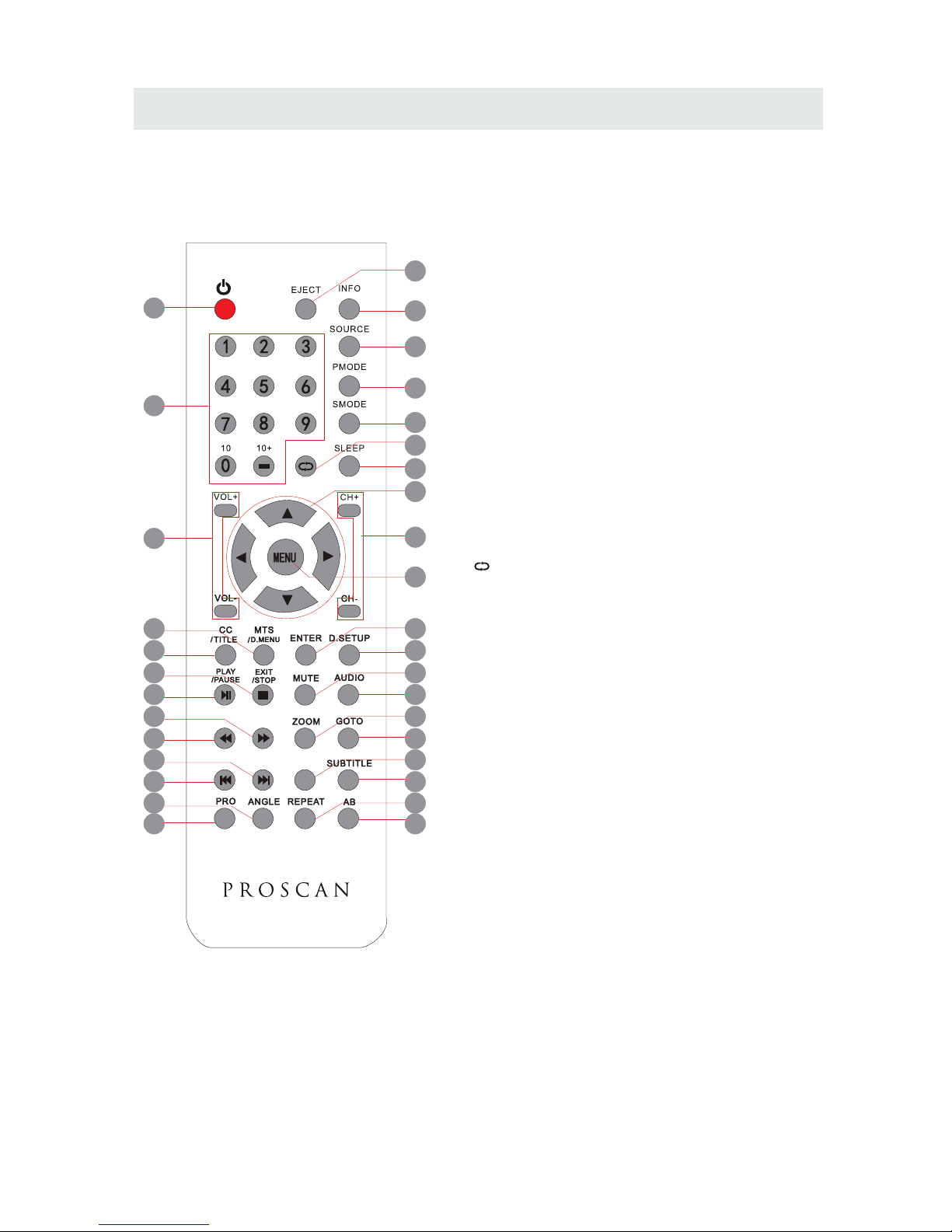
CONTROL REFERENCE GUIDE
REMOTE CONTROL
1.STANDBY
To switch on the TV or make the TV into
standby mode.
2.EJECT
To eject a disc.
3.INFO
Show the information of the program you are watching.
4.SOURCE
Press this button to select an input source.
5.PMODE
Press this button to select a picture mode for different
picture qualities.
6.SMODE
Press this button to select sound setting for different
sound effects.
7.0-9
Allows you to change the channel of the TV.
8.
Switches back and forth between the current and
previous channels.
9.SLEEP
To select the amount of time before your TV turns
Off automatically.
10.VOL+/VOLIncreases/Decreases the Volume control.
11.CH+/CHSkips to the next/previous channel on TV mode.
12.UP/DOWN/LEFT/RIGHT
Moves the cursor upward/downward/to the left/to the right
when making a selection.
13.MENU
Displays the OSD Menu of the TV.
14.CC
Press the button to enter into the CC mode.
TITLE
To goto the title menu if the DVD disc has a title page.
15.MTS
To change among STEREO, MONO and SAP. If there is no
second language available for the signal received, LCD
Display audio will output to mono.
D.MENU
To show the menu of the DVD disc.
4
5
1
2
3
6
8
9
12
7
11
13
10
15
14
19
18
23
22
27
26
31
30
16
17
20
21
24
25
28
29
32
33
FAVFAV
EPGEPG
4
Universal Remote Code: 1218
(Universal Remote Control is not included)
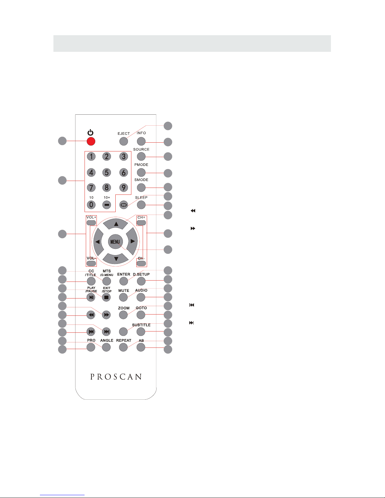
CONTROL REFERENCE GUIDE
REMOTE CONTROL
16.ENTER
Press to confirm selections on a menu screen.
17.D.SETUP
Press this button to show the DVD SETUP menu.
18.Play/Pause
Press this button to play or pause the DVD you’re watching.
19.Exit
Press this button to exit the on screen display.
Stop
Press this button to stop playing the DVD you’re watching.
20.MUTE
Press this button to mute or restore sound.
21.AUDIO
Press this button to change the audio language of the DVD.
22.
Fast reverse in DVD mode.
23.
Fast forward in DVD mode.
FAV
Press this button enter the favourite list.
24.ZOOM
To select a screen display size on your TV in DVD mode.
25.GOTO
Press this button to start playing the disc program from
the time you want.
26.
Previous chapter in DVD mode.
27.
Next chapter in DVD mode.
28.EPG
Press this button to select the electronic programme guide.
29.SUBTITLE
To show the subtitle for the program you're watching.
30.PRO
To edit the program list of your DVD disc in DVD mode.
31.ANGLE
To select different angles to which the picture suits your
preference.
32.REPEAT
Press this button for repeat the program.
33.AB
Press this button for repeat play point A and B.
4
5
1
2
3
6
8
9
12
7
11
13
10
15
14
19
18
23
22
27
26
31
30
16
17
20
21
24
25
28
29
32
33
FAVFAV
EPGEPG
Universal Remote Code: 1218
(Universal Remote Control is not included)
5
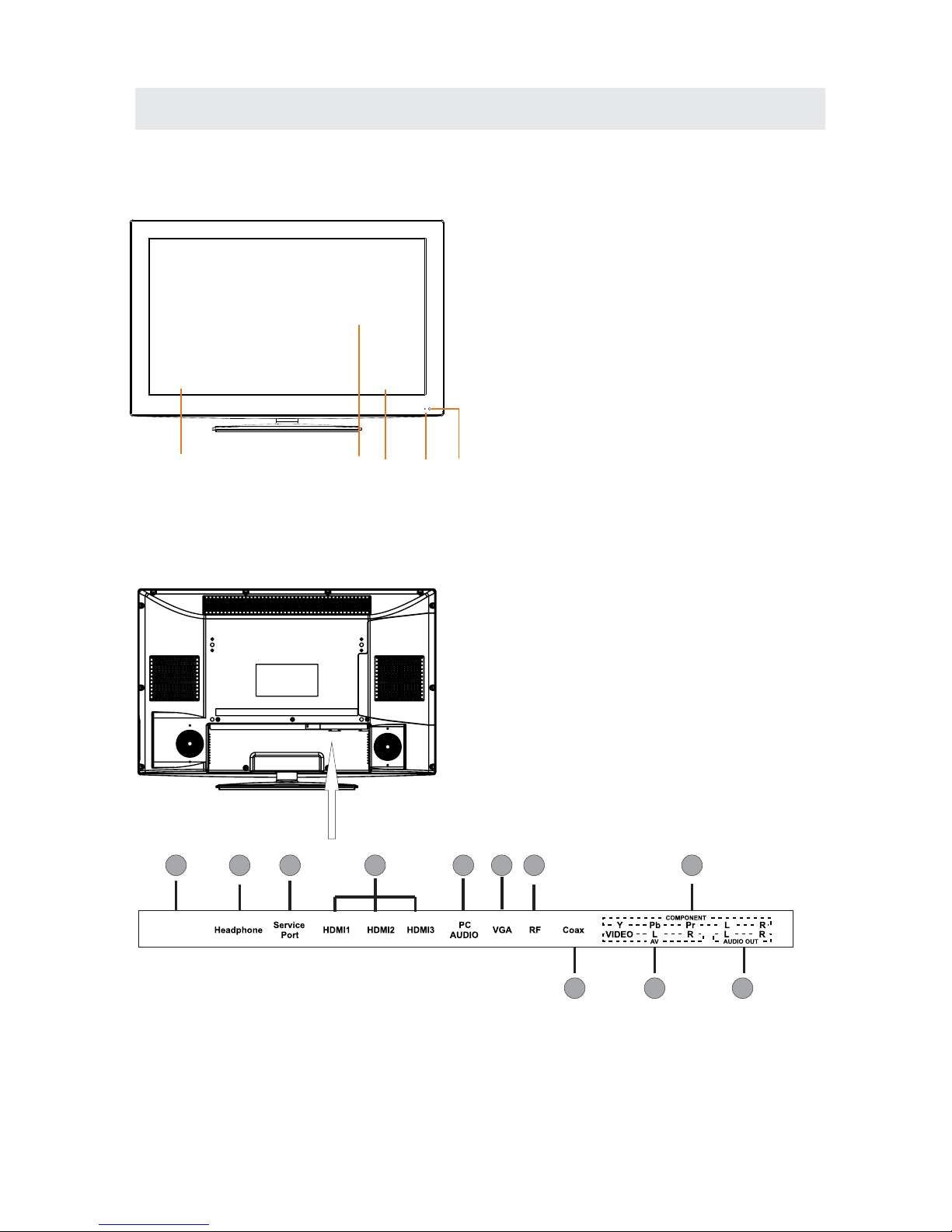
CONTROL REFERENCE GUIDE
FRONT VIEW
1.Color Screen
2.Remote Sensor
Do not block this sensor or the
remote control will not work.
3.Standby Indicator
Indicates whether the unit is ON
or in STANDBY (OFF) mode.
Light in red: The unit is in STANDBY.
Light in blue:The unit is turned ON.
4. Speakers
BACK VIEW
6
3
2
4
4
1
118
7
10
2 3
4
6
5
9
1.AC100-240V~ 50/60Hz
2.Headphone Jack
3.Service Port
4.HDMI IN Jacks
5.PC ADUIO IN Jack
6.VGA IN Jack
7.TV ANTENNA Terminal
8.Coax OUT Jack
9.AV IN Jack
10.COMPONENT IN Jack
11.AUDIO OUT Jack
(Audio out-This connection is for sending
out analog audio signal to the 2nd equipment.
Red is for Right Channel,white is for left channel.)
1
AC100- 240V~
1. VOL+
2. VOL-
. CH+
4. CH-
5. MENU
. SOURCE
7.
Bu tt o n
Bu tt o n
Bu tt o n
Bu tt o n
Button
6 Button
STANDBY Button
Press to adjust the volume up.
Press to adjust the volume down.
3
Press to change the TV channels and u p
highlight selectio ns on the men u screen.
Press to change the TV channels and d own
highlight selectio ns on the men u screen.
Press to display the on- screen TV m enu.
Press to select the input source of the TV.
Press to turn the unit on and off.
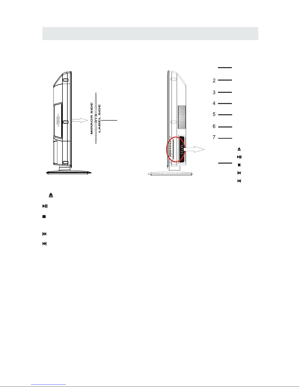
8.
To open or chose the DVD palyer loader.
Press this button to paly the DVD.
Press this button to stop playing the DVD
you’re watching.
Previous chapter in DVD mode.
Next chapter in DVD mode.
CONTROL REFERENCE GUIDE
9.Disc Slot
Insert discs to disc slot.
SIDE VIEW
(Right direction:put the label side of
the disc facing yourself)
7
9
Note:When inserting a disc,pleasetake
note of the indication of direction around
the disc slot for operation.
1
VOL+
VOL-
CH+
CH-
MENU
SOURCE
STANDBY
8
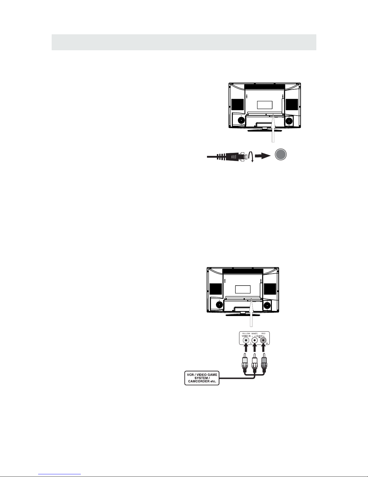
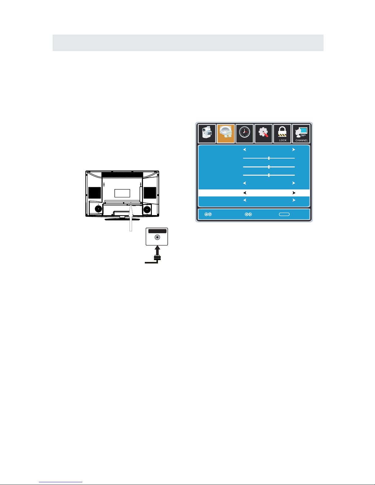
CONNECTIONS
CONNECTING A T V ANTENNA / CABLE / S A TELLITE
To vi ew television channels cor rec tly, a sig nal mu st
be receive d from one of the following source s:
- An indoor or outd oor ae ria l antenna
- A ca ble system
- A sa tellite sys tem
Fo r receiv ing ov er-the -ai r TV broa dca sts , we
reco mme nd th at yo u use an exter nal f ixe d anten na.
Sh oul d you req uire th e use of a te mpo rar y antenna,
pl ease ensure th at you purc has e an antenna with
su fficient ability to receive in wea k sign al areas.
On ly wh en you are in cl ose p ro ximity to a tr ans mit ter
wi ll a tempora r y an tenna reprodu ce a si gna l as
st rongl y as a fix ed antenna.
To co nne ct to other equipmen t such as a VCR, camcord er, sat ellite syst em or cab le, etc.
CONNECTING AN A/V DEVICE
NOTE
CONNECTING DEVICES WITH A COMPOSITE (YELLOW RCA-TYPE)
VIDEO OUTPUT
Connecting to a VCR / Video Game System / Camcorder
AUDIO VIDEO OUT
NOTE
To con nec t A/V d evi ces such as a VCR, video game sys tem o r cam corde r.
Co nnect the AUDI O / VID EO cab le (no t included) as shown.
Ma ke s ure you c onn ect t he ca ble f ro m the o the r equ ipm ent ( and ) to thi s uni t
Pl eas e re fer t o the user manual
fo r the other equipmen t for
mo re infor mat ion .
Sa te llite, cab le or TV ant en na
ca bl e to TV A NTENN A
term inal (ca bl e not inclu ded)
To AUDI O / VIDE O
IN j ac ks
To AU DI O / VIDEO
OU T jac ks
(AV in)
8
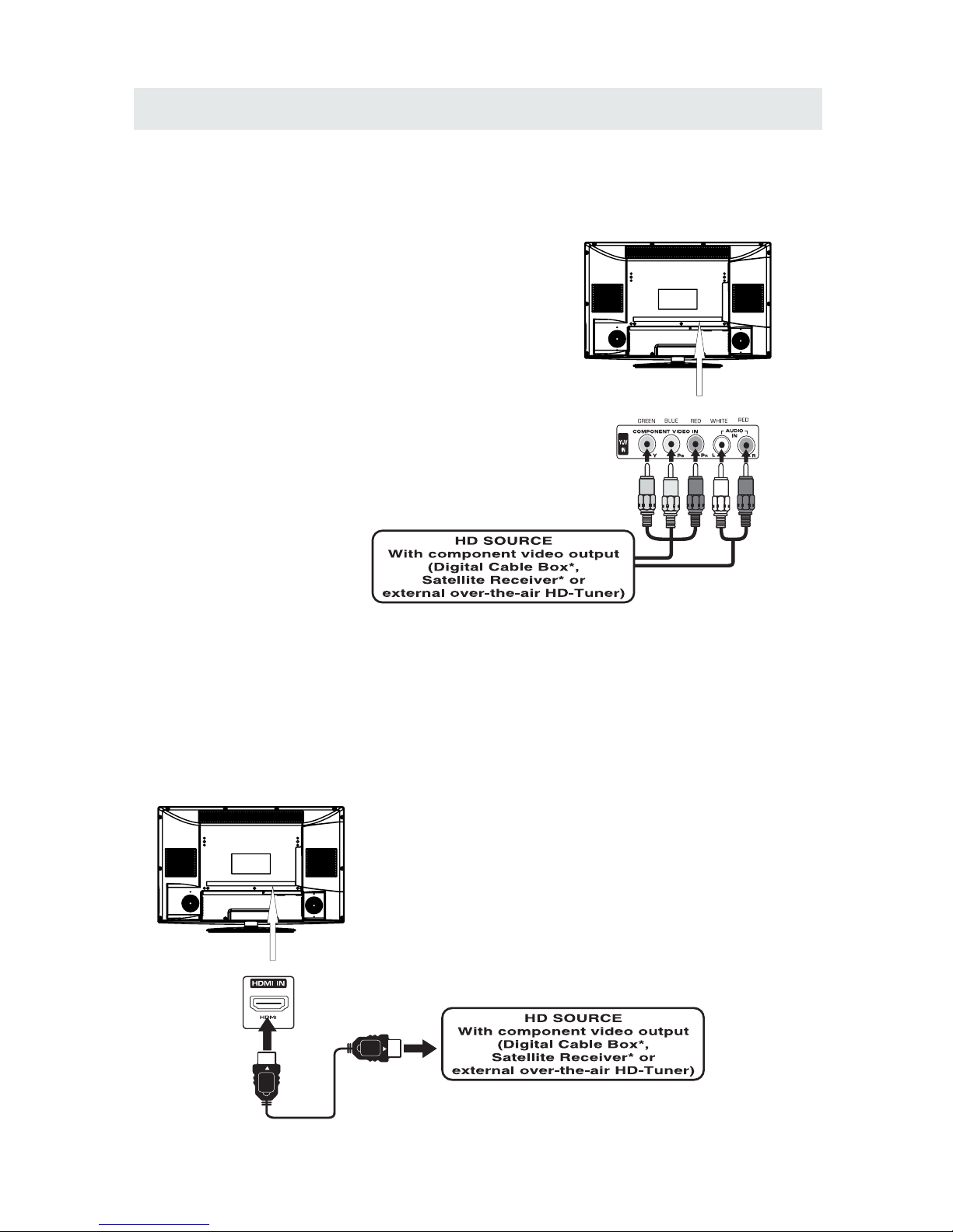
CONNECTIONS
CONNECTING A HIGH- DEFINITION (HD) SOURCE USING CONNECTION
NOT E
COMPONENT
High -Defini tion (HD) Dev ic es with compo nent video ou tput mus t be con ne cted to the Y input.
Conn ect the compo ne nt video cabl e and audio cabl e (not includ ed ) as shown.
Ma ke sur e yo u conne ct the co mp one nt v ideo ca ble and a udio ca ble from th e other e quipmen t
When conne cti ng a DVD player to the tel evision,
the picture res olution is sol ely de pendent upo n
the res olution sup por ted by th e DVD player atta che d.
DVD player resolut ion s var y from 480i to 1080p.
and this televisio n can sup por t DVD pla yer s up to
a maximum resoluti on of 108 0p.
PbPr
* May require a subscription
fo r receiving HD channels,
ch eck with your cab le/ sat ell ite
se r vic e prov ide r for det ail s.
To CO MPONE NT
VI DE O OUT jac ks
CONNECTING A HIG H-DEFINITION (HD) SOURCE USING HDMI CONNECTION
HDMI (H igh Defi ni tion Mul ti media In ter face) su pp orts both vide o and audio on a sin gl e digita l con necti on
fo r us e with DV D playe rs, DT V, set-t op boxes an d other d ig ita l AV de vic es . HDMI wa s devel op ed to provi de
the tec hn ologi es of Hig h Ban dwidt h Digita l Con tent Protect ion (HDC P) as we ll as Digi tal Visu al Inter face
(D VI ) in one sp ecifi catio n. HDCP i s us ed to protect d igita l content t ransm itted and rec eived b y
DVI- compl ia nt or HDMIc ompli an t displa ys .
HDMI ha s the capabil it y to suppor t stan dard, enha nc ed or high- de finit ion vide o plu s standa rd to
mult i-cha nn el surro un d-sou nd audio . HDM I features in clude un co mpresse d digital video, a bandwid th of
up to 2.2 gigab ytes per se co nd (with HDT V sign als), on e connecto r (instead of severa l cables an d
conn ector s), and commu nicat io n betwee n the AV sou rc e and AV de vi ces such as DTVs.
To HDMI
IN jack
To HDMI
ja ckOUT
To COMPONENT
VIDEO IN jacks
AU DI O IN jacks
To COMPONENT AUDIO
OU T ja cks
Co nn ect the H DMI cab le ( not i nc lud ed ) as
sh ow n:
Ma ke sur e yo u conne ct the ca bl e from th e
so ur ce equip me nt ( ) to this uni t
( ).
HD MI OU T
HD MI IN
HDMI CAB LE
(NOT INCLUDED)
(COMPONENT OUT and AUDIO OUT)to the unit COMPONENT IN.
COMPONENT IN
To COMPONENT
9
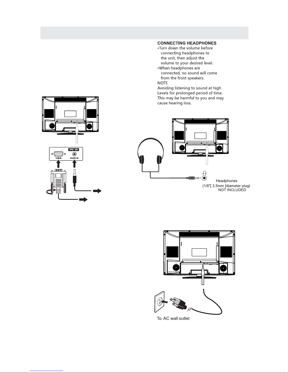
CONNECTIONS
CONNECTING A
AUDI O - PC O UT
VGA AUDI O - PC I N
PC
VGA
Co nn ect the 15- pin D-SU B PC/ VG A connec to r
from yo ur compu te r to the 15 -pin D-S UB PC/VGA
in pu t on this unit us ing a monit or ca ble and an
au di o cable (no t includ ed) as show n.
Ma ke sur e yo u conne ct the ca bl e from th e co mpute r
( an d ) to this uni t
( and ).
TO PC Connector
TO AUDIO OUT jacks
NOT E
• Insert the powe r plug fully into the socket outlet
If the power plug is loose it could generate heat and
cause fire
Do not tou ch the powe r plug wi th a wet hand
This may cau se electrical shock
Do not use any power cord ot her than that prov ided
with this TV This may cau se fire or elect rical shoc k
Do not d amage the power cord
A dama ged cord may ca use fire or ele ctric al shock
• Do not move the TV with the cord plugged in the
socket outlet.
• Do not place a heavy objec t on the cord or pl ace
the cord near a high-te mperature object.
• Do not twist the co rd, bend it excessively, or stretch it.
• Do not pull on the cord . Hold onto the power plug body when disco nnectin g cord.
• Do not use a damaged power plug or socket o utlet.
.
( ,
.)
.
( .)
. ( .)
.
( ).
•
•
•
connected to prevent electrical shock.
Ensure that the power plug is easily accessible.
Ensure the earth pin on the power plug is securely
•
•
10
CONNECTINGTHE POWER CORD
You can power on you r TV unit be fore yo u make su re t he powe r cord is i nsert ed well .
At the same time, please chec k that th e ra ted vol ta ge of your un it matche s yo ur lo ca l
Volt age.
CONNECTIONS
Set up
12
6
Tim
e
Soun d M od e
Ba ss
Treble
Ba la nce
Surround
St andard
Mo ve Se lect Return
MEN U
50
50
50
Of f
Pict ure Audio
Au dio Lan gu ag e
En glish
SP DI F Ty pe
PC M
Connection to a Home Theater Audio System
For BEST audio performance
Connecting to a Home Theater System
Dolby Digital can deliver optimal 2 channel
stereo or surround sound with five discrete
full range channels plus a sixth channel for
a subwoofer.
Enjoy optimal sound reproduction from your
system with a Dolby Digital amplifier that
incorporates a digital coaxial input. Connect
an optional digital cable directly to the
television’s Coax audio output to listen
through all inputs except VGA.
(The VGA does not support digital audio)
How To Setup Digital Output
Press the MENU button on the remote control
Press the right ► arrow button to select AUDIO
Press the down ▼ arrow button to highlight
SPDIF type right ► Raw or PCM
Coax
SPD IF OUT
11
 Loading...