

ProScan PLCD5092A-D User Manual

Model: PLCD5092A-D
50 ” TVLC D
USER’S MANUAL
USER’S MANUAL
Warning
To prev ent fir e and/or ele ctri c shock , do not us e this plug wi th an ex tensi on
cor d, rece ptacl e or other out let un less th e blades can b e full y inser ted to
pre vent bl ade exposu re. Do n ot expo se this appl ianc e to rain or moi stur e.
Important Safety Instructions
Rea d these i nstru ctions.
Kee p these i nstru ctions.
Hee d all war nings.
Fol low all i nstru ctions.
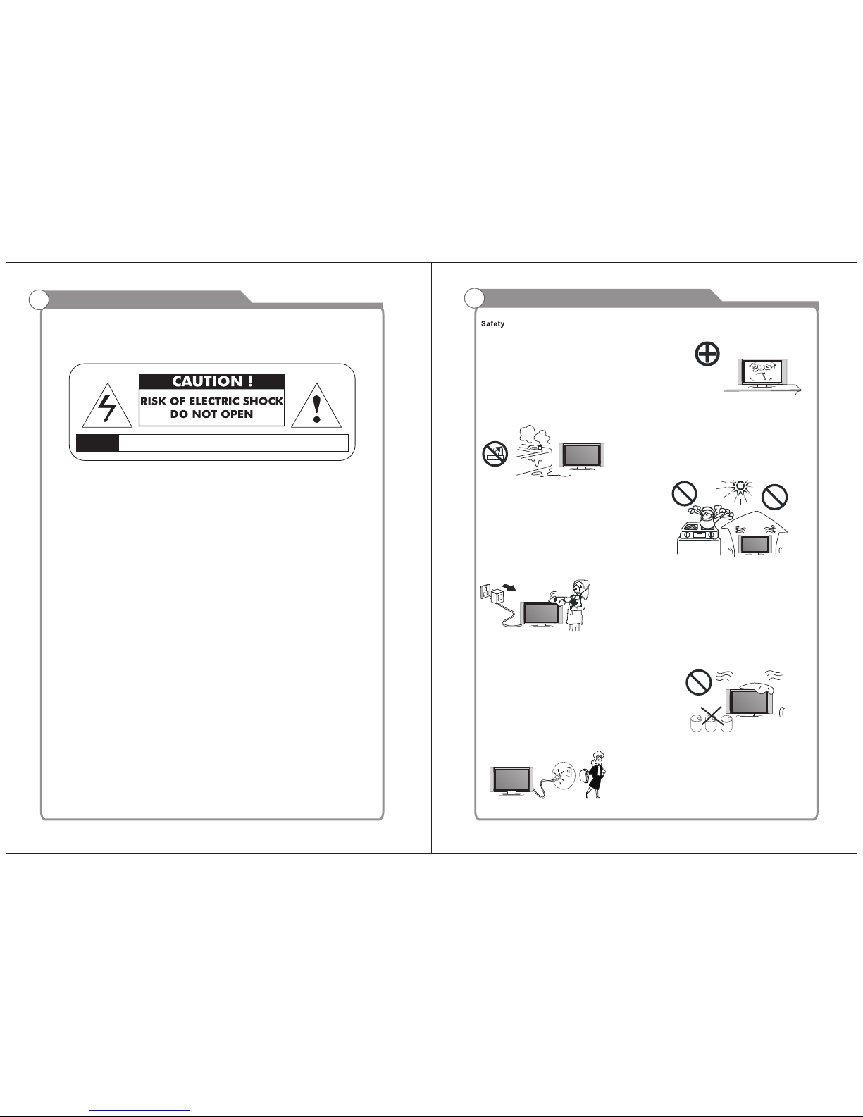
Ple ase, un plug th e TV po wer cor d when th e follo wing condi tion s occur:
-Wh en ther e is a thun derstorm ( Plea se, pul l out the p ower cord an d ante nna).
-Wh en clea ning th e TV se t.
-Wh en the TV s et is not use d for a long ti me.
Do no t use cor rosive dep urat ive when cle anin g the TV se t.
Do no t put the T V set under d irect sun light or ne ar hea t.
Do no t put a hea t sourc e, such a s a candle or he ater, o n top of or n ear the T V set.
Lea ve plen ty of spa ce (at least 1 0cm) a round the TV set for v entilat ion.
Pla ce the TV s et away fro m where it ca n be ruined b y rain o r water ( such as near a
win dow).
Don 't put a co ntain er with l iquid (suc h as a vas e) on top of the TV set.
Do no t move th e TV se t when th e power i s on.
Do no t touch , push or s cratc h the surfac e of the T V set with ha rd materi als or i tems.
Whe n TV su rfaces ar e dirty, ple ase us e a wet cot ton clo th or sof t cloth w ith non cor rosiv e cleaners t o clea n it careful ly. Don ´t use acet one, tolu ene or alco hol to
cle an the TV s et.
Be awa re and car eful of moistur e, which can damage inner electr onic compone nts.
When conden sed mo isture is p resent, t he TV sc reen may ap pear blur ry or spott y.
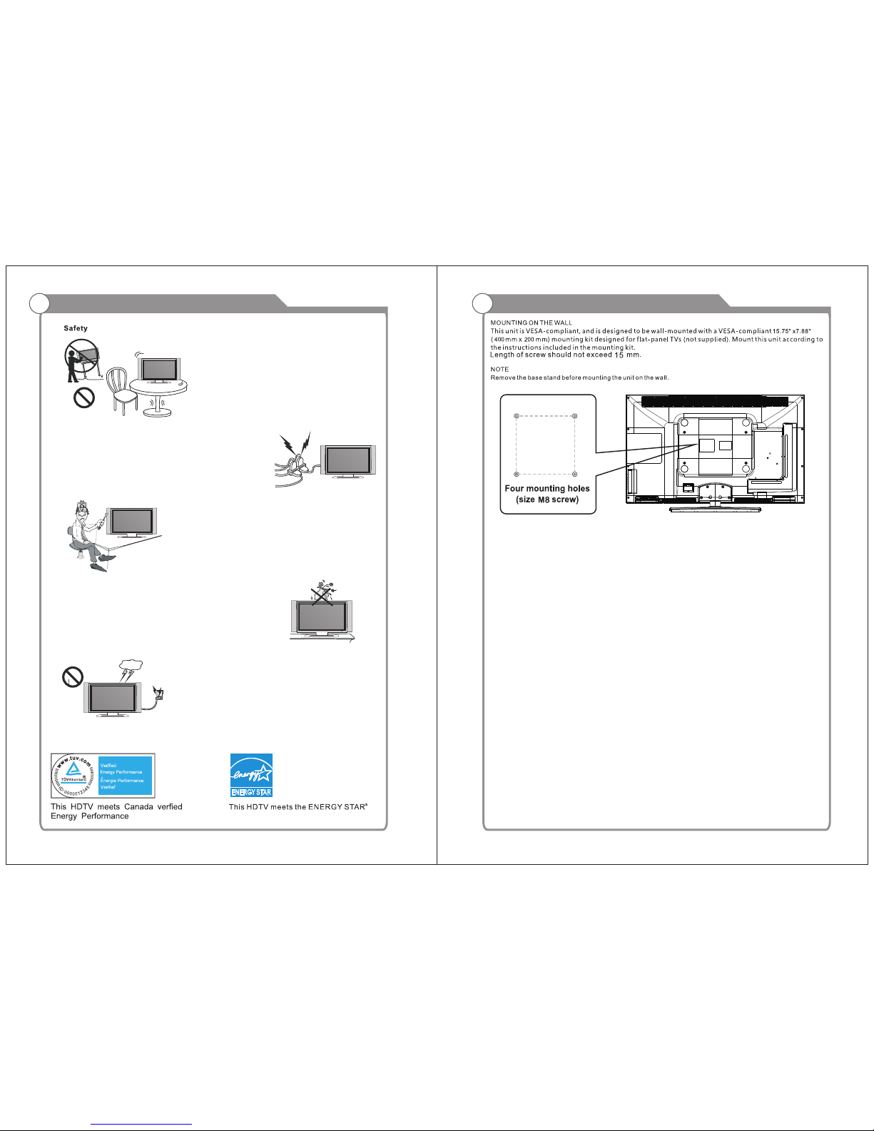
It is r ecomm ended t hat a tec hnician in stal l the TV se t on a wall, if s uch place ment is
des ired.
An in corre ct wall inst alla tion wi ll be unsafe a nd haz ardous.
Do not le t child ren climb on or play ar ound the TV set to avoi d falls, collis sions,
damages and injuri es.
Do no t hit the T V panel wit h hard obje cts to prev ent da mages.
Do no t cover t he TV set w ith blank ets or othe r objects w hen it i s conne cted to a
pow er sour ce to pre vent overh eati ng and fi re.
Batte ries shall not be exposed to excessive heat such as sunshine, fire or the like.
Mai ns plug i s used as disc onnect de vice f rom the m ains, t he discon nect
dev ice sha ll remain re adily ope rate .
App aratu s with cl ass I constr ucti on shall be co nnec ted to a ma ins socket
out let wit h a prote ctive e arthing co nnec tion.
Safety Information
AVIS RISQUE DE CHOC ELEC TRIOUE/NE PAS OUVRIR
Important Safety Precautions
Ple ase, im mediatel y pull o ut the AC power
plu g from ad apter i f there is an ab norm al
sou nd or sme ll or the L CD TV has s ound
but n o pictu re, and c ontac t after s ales
sup port.
The L CD TV sho uld be kept f ree from ra in,
moi sture a nd dust to pre vent e lectr ical
sho ck and sh ort circui ts. Do n ot cove r the
ven tilat ion ope nings with t able c lothe s,
cur tains , newsp apers, etc .
The L CD TV sh ould be kep t from h igh
tem perat ure he ating sou rces o r direct
sun light . Go od venti lation i s r equired .
All ow 10 cm. betwee n the LCD TV and
oth er appl iances or bu ilt- in cabinet w alls .
Whe n you wi pe the f ront ca binet, p lease
mak e su re the powe r p lug is pulled out and
use a soft , dry, lint-fr ee clot h and handle it
wit h care. Do not repeat edly wip e the panel,
nor s crape , tap or st rike th e panel with a h ard
obj ect.
Do not wipe the LCD TV w ith a ny petrol ,
che mical o r alcohol ba sed solve nts as i t
wil l lead to prod uct d amag e of the panel
and c abine t.
Whe n the tel evisi on receive r is not u sed for a n
ext ended p eriod o f time, it is ad visa ble to di sconnect
the AC p ower co rd from t he AC outlet.
The M AINS pl ug or an ap pliance co uple r is used as the
dis conne ct device, The dis connect d evice sha ll remain
rea dily op erable.
Do not pl ace the powe r c ord or other cables
acr oss a walk way in cas e it is t ramp led on. Do
not overloa d the power cord or po wer sock et.
Whe n the pow er plug i s used to disc onne ct and
con nect th e device, i t shou ld easily i nto th e
pow er sour ce.
Do no t place t he LCD TV o n an unstab le
sur face.
Do no t disa ssemble the back cover, as it
con tains h igh voltag es ins ide and will c ause
ele ctric shock. On ly qualif ied prof essio nals
sh ould co nduc t i nt er nal ad just me nt s,
mai ntena nce, an d checks.
The T V se t sh ould not be subje cted to
wat er dropl ets, vapor, or s plash . This
equ ipmen t should not b e plac ed on object s
fil led wit h l iquid s. D o n ot place flame
sou rces, such a s lit c andl es, on or near t he
LCD TV. Ple ase, pull out the po wer plug
and contact afte r sal es su pport if t here are
abn ormal o bjects or wa ter in t he TV.
Pul l ou t th e powe r cord and ant enna cab le
dur ing ele ctrical st orms s o the LCD T V is not
dam aged by e lectr ical surge s. Ke ep all
peo ple a way from the anten na ca ble during
ele ctric al stor ms.
Important Safety Precautions
WALL MOUNT INSTALLTION
15.75"
7.88"
SERVICE PORT
2
Introduction
W arnings
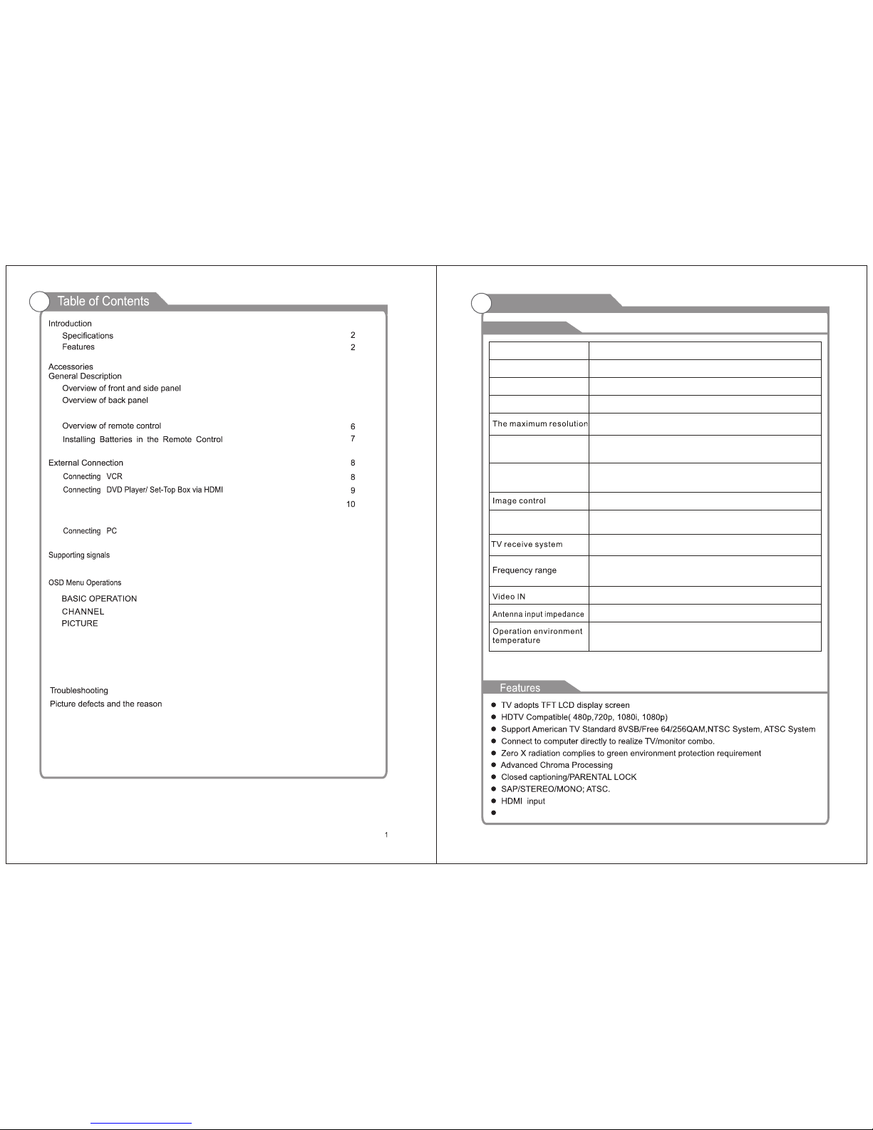
Specifications
Fine digital control
NTSC3.58
75W (Unbalance)
Model
Power adaptor
LCD
PLCD5092A-D
Display screen type Color active matrix LCD display
Sound output(Max)
2 x 10W
0 C-40 C
o o
Display Size
50”
Power Consumption(Max)
250W
1920X1080
Display Screen Type
100-240V 50/60Hz
Rem arks:
The a bove li sted sp ecificat ions a nd data a re subject t o chan ge without p rior n otice .
Antenna: 2~69; Cable: 1~135 (Analog: 1-125,
Digital: 1-135)
Connecting Digital Audio System
Connecting DVD Player/Set-Top Box via HDMI
11
12
12
13-16
13
AUDIO
TIME
LOCK
13
14
14
15
16-17
18
19
SETUP
15
1
NTSC System, ATSC System
3
3-7
3
4
5
Install LCD SET

3
Accessories
Please make sure the following items are included with your LCD TV. If any items are
missing, contact your dealer.
Remote Control &
Batteries (AAAx 2)
Owner’s
Instructions
SPEAKER
REMOTE CONTROL SENSOR
Aim the remote control towards this
spot on the TV.
POWER INDICATOR
Green: In power on mode.
Red: In standby mode.
Toggles between all the available input
CH+/ Press to change channels. In the on-screen menu, use the CH +/-
buttons as up/down arrow buttons.
VOL+/ Press to increase or decrease the volume.
In the on-screen menu, use the VOL +/ buttons as left/right arrow buttons.
POWER
Press POWER button to toggle between normal and standby mode.
MENU
Press to see an on-screen menu of your
TV's features.
SOU RCE
4
5
6
8
sources ( TV, AV, PC) Componente, HDMI 1, HDMI 2, HDMI 3,
General Description
Overview of front and side panel
Warranty Card
Assembllng
Stand Process
7
4
General Description
Overview of back panel
COAXIA L
OUT
RF
IN
VGA
IN
PC AUDIO
IN
HDMI 1 HDMI 2 HDMI 3
1 2 3 4 5 6 7 8
Pr
VIDEO R
L
VIDEO R
9
10
Pb
Y
L
11
OUT
1.
2.
COAXIA L: ou tput
RF: inpu t
3. VGA(P C): i nput
4. PC AUDIO: inpu t
5. HDMI 1: i npu t
6. HDMI 2: i npu t
7. HDMI 3: i npu t
8. SERVICE POR T
9. VIDEO : out put
10. VIDE O: in put
11. YP bPr: input
SERVIC E
PORT
6
Overview of remote control
General Description
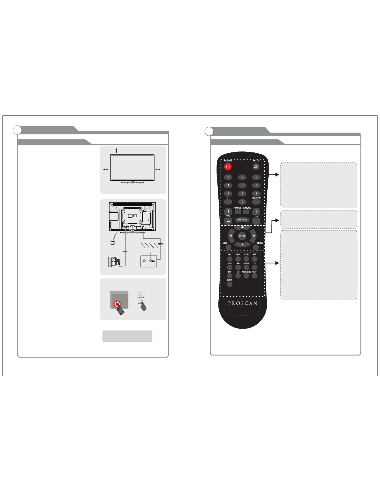
POWE R: Turn t he TV on or o ff.
MUT E: Pres s to mute t he soun d, Pres s again t o regai n
the so und.
0-9 : Press 0 -9 to sel et a TV chan nel dir ectly T he chan nel
wil l chang e after 2 s econd s.
-/- -: Pres s this bu tton fi rstly w hen the c hanne l to be
sel ected i s two or th ree fig ures (o nly DVD m ode).
RET URN: Re turn to t he prev iousl y viewe d progr am.
P.MODE : Selec t the pic ture mo de.
S.M ODE: Se lect th e sound m ode.
SOU RCE: Pr ess to se lect si gnal so urce fo r TV.
VOL+ /-: Pr ess the se two bu ttons to i ncre ase/d ecrea se the
sou nd volu me.
CH+ /-: Pre ss thes e two but tons to c hange c hanne ls
seq uentl y.
▲▼ ◀▶/ent er: Allo ws you to n aviga te the on -scre en
menu s and ad just th e syste m settin gs to yo ur
pref erenc e.
EXI T: Exit fro m the men u or sub me nu.
MEN U: Allo w you to na vigat e the on- scree n menus .
EPG : Press t o displ ay EPG (E lectr onic Pr ogram G uide) i n
for matio n.
INFO : Disp lays th e chann el in for matio n.
ZOOM : Pres s to chan ge the sc reen sc ale.
MTS : Press t o selec t the aud io chan nels.
LOCK : Pres s to disp lay the p arent al menu .
TIME : Pres s to disp lay Time m enu.
FRE EZE: Pr ess to fr eeze th e scree n.
CC: P ress to d ispla y the clo sed cap tion.
LIST: P ress to d ispla y the TV pro gram li st.
FAV: Pres s to disp lay the f avori te prog rams.
ADD : Add thi s progr am to the f avori te lang uage.
ERA SE: Del ete thi s progr am from t he favo rite ch annel s
lis t.
FAV+/- : Press t his but ton +/- t he favo rite pr ogram l ist.
SLE EP: Set u p the tim e how lon g the TV wil l turn of f.
Accessories
1.Se t your LC D TV set
Put y our LCD T V set in a firm p lace
tha t can bea r its wei ght.
To avoi d danger, ple ase do n ot expose
the L CD TV set t o water or he at (such
as a li ght, ca ndle, o r heati ng machine ).
Do no t block t he vent ilati on on the
bac k of the LC D TV se t.
2.Co nnect a ntenn a and pow er
a.Co nnect t he ante nna cable to t he
ant enna so cket on t he back of the
LCD T V set and to yo ur antenn a sock et.
b.Pl ug in the p ower co rd of the L CD
TV se t (AC 100 -240V ~50/6 0Hz).
c.Th e TV is t urned off w hen th e switc h
(AC 1 00-24 0V 50/60Hz ) is at“ 0”,
and p ower on t he TV whe n the switc h
(AC 1 00-24 0V 50/60Hz ) is at “I ”.
3.Tur n on the set
If th e LCD TV se t is in stand by mode
(th e light i s red), p ress th e POWER
but ton on th e remot e contr ol to tur n
on th e set.
NOT E
Pic ture on ly for re feren ce
10 cm
10cm10cm
POWER
Install LCD SET
5
POWER SWIT CH
AC 10 0-240 V
50/ 60Hz
ANT 75 Ω
TV si gnal

COAXIA L
OUT
RF
IN
VGA
IN
PC AUDIO
IN
HDMI 1 HDMI 2 HDMI 3
Pr
VIDEO R
L
VIDEO R
Pb
Y
L
OUT
7
8
Installing Batteries in the Remote Control
Installing BatteriesInstalling Batteries
1
Open the battery compartment
cover on the back side.
2
Insert two 1.5V AAA size batteries in
correct polarity. Don´t mix old or used
batteries with new ones.
3
Closed the cover.
Point the remote towards the remote
control sensor of the wireless TV and
use it within 7 meters.
Put the used batteries into the recycling bin since it can negatively affect
the environment.
General Description
Battery
Cover
2xsize AAA 1.5V
Battery
Cover
Antenna connection
Antenna input impedance of this unit is 75ohm. VHF/UHF 75ohm coaxial cable can be
connected to the antenna jack directly, if the antenna cable is 300ohm parallel flat feeder
cable, you need to use the 300ohm/75ohm converter to connect the antenna cable to the
antenna jack. For details Please refer to the following drawing.
Use a 75ohm - 300ohm converter
300ohm coaxial cable
Antenna feeder
ANT IN
75ohm coaxial cable
Antenna cable
Antennas with 300 flat twins Leadsohm
Antennas with 75 Round Leadsohm
External Connection
The batteries shall not be eposed to ecessive heat such as sunshine
fire of the like.
External Connection
Connecting VCR
These instructions assume that you have already connected your TV to an antenna or a
cable TV system. Skip step 1 if you have not yet connected to an antenna or a cable
system.
Follow the instructions in Viewing a VCR or Camcorder Tape to view your VCR tape.
Each VCR has a different back panel configuration.
When connecting a VCR, match the color of the connection terminal to the cable.
We recommend the use of cables with a Ferrite Core.
1. Unplug the cable or antenna from the back of the TV.
2. Connect the cable or antenna to the ANT IN terminal on the back of the VCR.
3. Connect an RF Cable between the ANT OUT terminal on the VCR and the ANT IN
terminal on the TV.
4. Connect a Video Cable between the VIDEO OUT jack on the VCR and the VIDEO IN
jack on the TV.
5. Connect Audio Cables between the AUDIO OUT jacks on the VCR and the AUDIO L and
AUDIO R jacks on the TV.
If you have a mono (non-stereo) VCR, use a Y-connector (not supplied) to hook up to
the right and left audio input jacks of the TV. If your VCR is stereo, you must connect
two cables.
VCR Rear Panel
RF Cable
(Not supplied)
Video Cable
(Not supplied)
Audio Cable
(Not supplied)
Not e: The AV ou tput can b e used on ly when t he inpu t signa l is AV or TV.
TV
TV AV INPUT
SERVIC E
PORT
COAXIA L
OUT
RF
IN
VGA
IN
PC AUDIO
IN
HDMI 1 HDMI 2 HDMI 3
Pr
VIDEO R
L
VIDEO R
Pb
Y
L
OUT
9
10
External Connection
and the AUDIO OUT jacks on the DVD player.
the TV and the COMPONENT [Y, PB, PR] jacks on the DVD player.
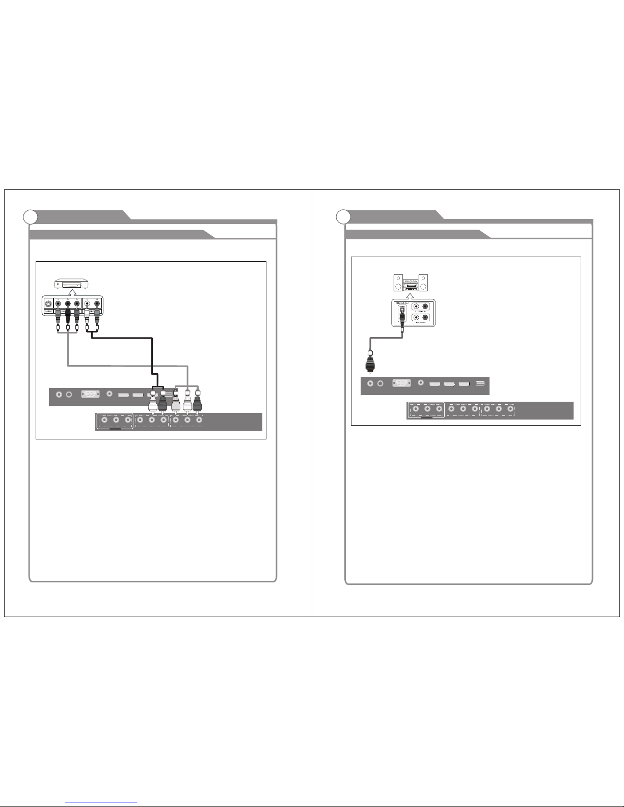
Connecting DVD Player/Set-Top Box
The rear panel jacks on your TV make it easy to connect a DVD to your TV.
Component video separates the video into Y (Luminance (brightness)), Pb (Blue) and Pr
(Red) for enhanced video quality.
Be sure to match the component video and audio connections.
For example, if connecting the video cable to COMPONENT IN, connect the audio
cable to COMPONENT IN also.
Each DVD player/STB has a different back panel configuration.
When connecting a DVD player/STB, match the color of the connection terminal to the
cable.
We recommend the use of cables with a Ferrite Core.
1. Connect a Component Cable between the COMPONENT IN [Y, PB, PR] jacks on
2. Connect Audio Cables between the COMPONENT IN [R-AUDIO-L] jacks on the TV
Audio Cable (Not supplied)
Component Cable (Not supplied)
DVD Player/Set-Top Box
External Connection
Connecting Digital Audio System
The rear panel jacks on your TV make it easy to connect a Digital Audio System to your TV.
5.1 CH audio is possible when the TV is connected to an external device supporting 5.1
CH.
We recommend the use of cables with a Ferrite Core.
1. Connect an COAXIAL Cable between the SPDIF jacks on the TV and the Digital Audio
jacks on the Digital Audio System. When a Digital Audio System is connected to the Input
SPDIF terminal: Decrease the gain (volume) of the TV, and adjust the volume level with
the system's volume control.
Digital Audio System
COAXIAL Cable
(Not supplied)
COAXIA L
OUT
RF
IN
VGA
IN
PC AUDIO
IN
HDMI 1 HDMI 2 HDMI 3
Pr
VIDEO R
L
VIDEO R
Pb
Y
L
OUT
SERVIC E
PORT
SERVIC E
PORT
 Loading...