

Pro Products ProFeeder Installation & User Manual
PRODUCT
WARRANTY INFORMATION
WARRANTY & DISCLAIMER
Pro Products warrants to the initial purchaser of this product that it will be free from defect in material or workmanship under normal
intended use for a period of one year from the date of purchase. This limited warranty is not transferable. This limited warranty does not
include those parts which fall under standard regular maintenance of an irrigation system including as set forth in the Pro Products product
instructions. The remedy under this limited warranty is limited to repair or replacement, at Pro Products, LLC option, of the defective parts
of the warranted product. Repair or replacement of a part does not extend the warranty beyond the initial warranty period. This is the only
warranty applicable to the product. To the fullest extent allowable by law, the duration of any implied warranty applicable to the product is
limited to the one year duration of this express warranty.
*Profeeder is designed to be used with chemicals produced by Pro Products, LLC. Any other chemicals used in the Profeeder will void the warranty.
LIMITATION OF LIABILITY
TO THE FULLEST EXTENT ALLOWED BY LAW, THE FOREGOING WARRANTY AND REMEDIES ARE EXCLUSIVE AND ARE IN LIEU OF ALL OTHER
WARRANTIES, TERMS OR CONDITIONS, EXPRESS OR IMPLIED. THIS LIMITED WARRANTY DOES NOT APPLY TO CONDITIONS RESULTING FROM
IMPROPER INSTALLATION, MISUSE, ABUSE, AND FAILURE TO FOLLOW DIRECTIONS FOR USE, UNAUTHORIZED MODIFICATIONS, NEGLECT,
ACCIDENT, HAZARD, ACTS OF GOD, OR THE LIKE. TO THE FULLEST EXTENT ALLOWED BY LAW, PRO PRODUCTS, LLC ALSO EXCLUDES FOR ITSELF
AND ITS SUPPLIERS ANY LIABILITY, WHETHER BASED IN CONTRACT OR TORT (INCLUDING NEGLIGENCE), FOR DAMAGE TO TURF, PLANTS
OR LANDSCAPE, FOR INCIDENTAL, CONSEQUENTIAL, INDIRECT, SPECIAL OR PUNITIVE DAMAGES OF ANY KIND, FOR LOSS OF REVENUE OR
PROFITS, BUSINESS INTERRUPTION AND LIMITS ITS LIABILITY TO REPLACEMENT, REPAIR OR REFUND OF THE PURCHASE PRICE PAID, AT PRO
PRODUCTS, LLC OPTION.
Some countries, states or provinces do not allow the exclusion or limitation of implied warranties or the limitation of incidental of
consequential damages for certain consumer products, so the above limitations or exclusions may not apply to you. This warranty gives you
specific legal rights that may vary depending on local law.
CONTACT INFORMATION
Pro Products, LLC
7201 Engle Rd
Fort Wayne, IN 46804
TOLL FREE 800.285.9176
FAX 260.490.9431
EMAIL info@proproducts.com
WEB www.americanhydro.com
4
INSTALLATION / USER’S GUIDE
AUTOMATIC FERTILIZING
& PEST CONTROL SYSTEM
Preparing for Installation
Before installing the ProFeeder, read all of the instructions carefully. It’s a
good idea to do a “dry run” installation (without cutting, applying glue, or
assembling the tank), to be sure you understand the instructions before
permanently attaching components. Each 1 gallon refill feeds up to 5 ,000 sq.
ft. of turf per month. The device installs into a 1” line or adapts to a 3/4” line
with the appropriate adapters (not included).
Where to Install Your ProFeeder
The ProFeeder can be installed on either a pressurized or non pressurized line.
To feed your entire landscape, install the device on the pressurized side of
the line (mainline) after your backflow prevention device and before all valve
boxes (or “T’s” in the line). All areas of the landscape down-stream from the Pro
Feeder will be fertilized and/or free from pests. To feed a specific area in your
landscape, install the device on a non pressurized section after the valve. A
code-compliant back flow prevention device is required on all installations.
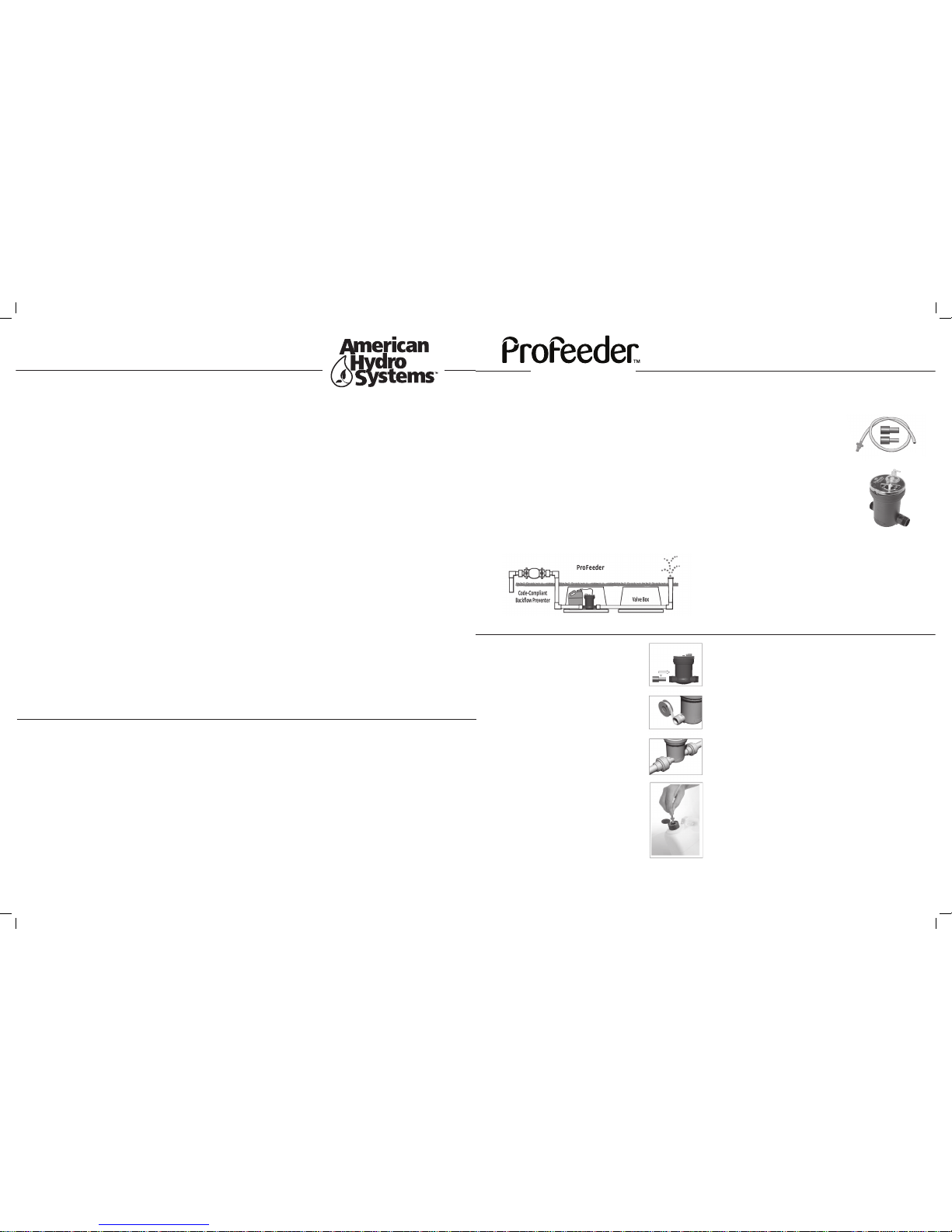
In the Box:
The following items are included in your box
A. Injector & Body (black section)
B. Flow Directors (1 Blue, 1 Red)
C. Fertilizer retrieval hose with blue quick
connect Siphon
D. Installation manual
Additional Items Needed:
The following items are not included but may be required.
☑ A Shovel
☑ Phillips Screwdriver
☑ PVC Cutter or Hack Saw
☑ PVC Primer and Glue
☑ Adaptors. For 1” PVC, we recommend that you purchase
1 THREADED PVC UNION (1” NPT) and 1 SLIP PVC UNION adapter (1” NPT)
from the same manufacturer so that you can interchange the parts to
create 2 complete union assemblies with one threaded side, and one slip
side on each.
☑ Teflon® Pipe Tape
☑ Standard Valve Box (required to protect the device)
Installing the Injector
Install the ProFeeder in a 12” standard or jumbo valve box to
protect the device from the elements. Install in an area that
is not likely to be flooded with water. Make sure to install
the device so that there is enough room for the injector and
1 gallon bottle of fertilizer.
1. Shut off the water supply
Tip: You may also want to manually open one valve to
allow water to drain out of the line.
2. Dig the hole
Dig your hole between your back flow device and the
first valve box in your system. Make sure the hole is big
enough to accommodate a standard valve box.
3. Cut out a Section of Pipe
Cut out the minimum amount of pipe required to
accommodate the adapters you have chosen to install
into sprinkler system.
4. Insert the Flow Director
The Flow Director (Part B) nozzle controls the
fertilizer injection rate. Install nozzle into the side of
the injector base labeled “From Main” (Figure 1) see
included nozzle chart 4 the appropriate nozzle for
your application.
5. Apply Teflon Tape to Threads
Apply Teflon Tape to the threads on the injector base
to minimize the potential of leaking. Apply no pipe
dope. See (Figure 2)
6. Install the ProFeeder Injector (A)
Using the adapters you purchased separately for your sprinkling system,
install the Pro Feeder with the arrow pointing in the direction of
the water flow. Allow any glued connections to dry before pressurizing.
Make sure that a Flow Director (step 4) is present before proceeding or
your device may not function properly. To facilitate future access to the
Injector and fittings, LEAVE THE BASE OF THE INJECTOR EXPOSED.
7. Install Valve Box
Install valve box so that underside of lid clears the top of the ProFeeder
by at least 1” to prevent interference with operation of ProFeeder.
Attaching Fertilizer or NatureShield® Bottle
8. Attach the Siphon Hose (C) to the Siphon Cap (A)
FIRST TIME INSTALLATION ONLY: Press the gray swivel elbow (opposite
the blue quick connect) over the nipple on the Siphon Cap so that it is
snug and air-tight.
9. Attach the BLUE Quick Connect on the other end of the Retrieval
Hose to the Bottle.
Lift the tab on the fertilizer bottle cap and press the blue adapter into
the hole.
10. Self Priming
Ensure the unit is in the “ON” position. When water begins flowing
through the unit, product will begin drawing through the tube. Allow
2-10 min for this to take place depending on flow rate.
Note: Profeeder can be installed vertically or hoizontally.
*Profeeder is designed to be used with chemicals produced by Pro Products,
LLC. Any other chemicals used in the Profeeder will void the warranty.
Figure 1: Insert a flow director
Figure 2: Apply Teflon Tape
Figure 3: Typical Installation
Figure 4: Open the bottle cap and
press the Blue quick connect into
the opening on the bottle.
A
B
C

Turn OFF Water Main
Turn OFF the water main, bleed
off pressure from mainline.
Remove Siphon Cap
Remove the screw in the
center of the siphon cap.
Lift off so the injector is
exposed as shown. (Fig 1)
Remove Snap Ring
Press firmly on the top of the
INJECTOR with your thumbs to
relieve pressure on the SNAP RING.
Insert a screw driver into the LIFT
TAB and gently pull in and then up
to remove the SNAP RING.
Remove Old Injector
Grab the INJECTOR PORT and
gently pull up. The INJECTOR
should slide out easily.
Clean & Reinsert O-Ring
Clean the O-RING. Apply a small amount
of plumbers grease before reinserting to
ensure a good seal. Set the O-RING on the
SHOULDER inside the INJECTOR BODY
Insert the New Injector
Push the INJECTOR down until it stops.
Turn the INJECTOR clockwise until the
ALIGNMENT GROOVE & TAB meet allowing it to nest inside the INJECTOR BODY.
Firmly press down to ensure a snug fit.
Replace the Snap Ring
Make sure the LIFT TAB on the SNAP RING
is facing up and that it “snaps” into position before restoring water pressure.
Turn ON Water Main
STAND AWAY FROM THE INJECTOR WHILE IT
IS PRESSURIZING
. Check for leaks around
the SNAP RING and the INJECTOR PORT.
Reattach the siphon cap and continue
normal use.
1
2
3
4
SNAP RING
LIFT TAB
INJECTOR INJECTOR
PORT
ALIGNMENT
GROOVE
INJECTOR BODY
SHOULDER (Inside Body)
ALIGNMENT
TAB (Inside)
O RING
5
6
7
8
REPLACING THE
INJECTOR UNIT
AUTOMATIC FERTILIZING
& PEST CONTROL SYSTEM
WINTERIZATION &
SERVICE OF PROFEEDER
SNAP RING
LIFT TAB
INJECTOR BODY
SHOULDER (Inside Body)
ALIGNMENT
TAB (Inside)
O RING
SERVICE PLUG
WINTERIZATION OF THE PROFEEDER
Do not inject air into a sprinkling system
that has a ProFeeder installed without first
installing a service plug or temporary bypass.
Injecting air into the sprinkling system will
spin the internal impeller and gear system of the
ProFeeder too fast which will cause damage
to the injector. The ProFeeder Service Plug is
designed to facilitate air injection for winterization or
temporary replacement of the
injector element for service.
Remove Siphon Cap
Remove Snap Ring
Gently pull out injector
Insert Service Plug
Replace snap ring
Perform winterization services
Remove Snap Ring & Plug
Clean, Grease & Replace O-Ring
Clean build-up on Injector
Insert Injector
Replace Snap Ring
Replace Siphon Cap
1
2
3
4
5
6
7
8
9
10
11
12
INSTALLING THE SERVICE PLUG
Turn off water main and bleed mainline
pressure before proceeding.
2
Fig 1
INJECTOR NOZZLE GUIDE
AUTOMATIC FERTILIZING
& PEST CONTROL SYSTEM
High flow range for spray and roter
zones. Dilution ratio of 10,000 15,000 : 1*
Moderate to High flow range. For
spray and rotor zones. Dilution
ratio of 4,000 - 5,000 : 1*
Low to Moderate flow range. For
spray zones and large drip zones.
Dilution ratio of 2,400 - 3,600 : 1*
*Gallons of water : 1 gallon fertilizer
RECOMMENDED USE OPERATING RANGE
up to 40 GPM
10 – 25 GPM
3 – 12 GPM
NO NOZZLEBLUE
RED
3
Part # Description
A1X-GTS Internal Pump Mech
P1X-SVC Plug Service Plug
R-O Ring Internal O Ring (Black)
R-Snap Ring Internal Snap Ring (Yellow)
A1X-TK-1 P1X Tubing Kit for 1 gallon bottle
A1X-UP2 Second generation siphon cap
1
2
3
4
5
6
PROFEEDER REPLACEMENT
PARTS LIST
 Loading...