

PA470-D
5/3/05 NK/AH
PA470-D TEST BOX INSTALLATION & USE GUIDE
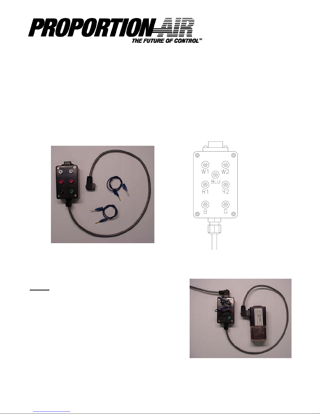
Product Description
The PA470-D is a troubleshooting tool that allows you to check the command signal input, the analog
monitor output, and power supply of your standard¹ QB3 (and other units with differential input using
the same connector) using an electrical multimeter without having to gain access to electrical connections in a cabinet which may be remotely mounted. The PA470-D consists of the test box and 2 pin tip
patch cords (PN H4444). See Figures 1 and 2.
¹ If the QB control valve has any special modifications, consult factory before wiring the box.
Figure 1
Product Operation
Set up
1. Remove the cord from the unit to be tested and plug it
into the PA470-D.
2. Plug the cord from the PA470-D into the unit to be
tested.
3. Plug one of the H4444 patch cord into the white jacks
(W1 and W2).
4. Plug the other H4444 patch cord into the red jacks (R1
and R2). See figure 3
1/4
Figure 2
Figure 3
PA470-D INSTALLATION

Product Operation
Review Figure 1 for socket identification before proceeding.
Power Input Test
This test will ensure that the Proportion-Air unit is receiving the correct voltage from your power supply.
1. Set your meter to D.C. voltage.
2. Plug the negative probe from the meter into the
green socket (G).
3. Plug the positive probe from the meter into the
black socket (B).
4. The voltage should read between 15 and 24 volts
on standard Proportion-Air units.
5. If the voltage reading is not in this range, unstable,
or negative, check the power supply and wiring.
See figure 4
Command Signal Input Test
This test will verify that the Proportion-Air unit is receiving a good command signal.
Figure 4
PA470-D
5/3/05 NK/AH
Differential Voltage Commanded Units
This is for Proportion Air units that have TFEE for
TFEC in their part number string.
1. Plug one of the H4444 patch cord into the white
jacks (W1 and W2). Plug the other H4444 patch
cord into the red jacks (R1 and R2).
2. Set your multimeter to D.C. voltage.
3. Put multimeter’s negative probe in the blue socket
(BLU) and the positive probe in the socket of either
end of the patch cord.
4. The voltage displayed on the multimeter should be
the same as the controller is out putting. (Command
signal) See figure 5
Current Commanded Units
This is for Proportion Air units that have TFIE or
TFIC in their part number string.)
1. Remove H4444 patch cord from W1 and W2 white
jacks.
2. Set your multimeter to milliamps.
3. Put positive probe in W1 white jack. Place negative probe in W2 white jack.
4. Reading should be the same as the controller is
outputting to the unit. See figure 6
Figure 5
2/4
Figure 6
PA470-D INSTALLATION

PA470-D
5/3/05 NK/AH
Analog Monitor Signal Output Test
This test will verify that the Proportion-Air unit’s monitor signal and controlling transducer are working properly.
Voltage Analog Monitor Output Signal Test
This is for Proportion Air units that have TFEE or TFIE in their part number string.)
1. Plug one of the H4444 patch cord into the white jacks (W1 and W2).
2. Plug the other H4444 patch cord into the red jacks (R1 and R2).
3. Set your multimeter to D.C. voltage.
4. Put multimeter’s negative probe in the green socket (G) and the positive probe in the socket of either end of the patch cord that is plugged into the red jacks (R1 and R2).
5. The voltage displayed on the multimeter will be the equivalent of the pressure (vacuum, force,
torque, position, or flow) that the controlling transducer (on board if a QB1 or QB3, external if a
QB2) is sensing. If this value is 0 or is a fixed value regardless of what happens downstream, the
analog monitor may not be functioning or the second loop transducer may be inoperable. See figure 7.
Figure 7
3/4
PA470-D INSTALLATION

PA470-D
5/3/05 NK/AH
Current Analog Monitor Output Signal Test
This is for Proportion Air units that have TFEC or TFIC in their part number string.)
1. Plug one of the H4444 patch cord into the white jacks (W1 and W2). Remove the other H4444
patch cord from the red jacks (R1 and R2).
2. Set your multimeter to milliamps.
3. Put multimeter’s positive probe in the left red (R1) patch cord socket and the negative probe in the
right red (R2) patch cord socket.
4. The current displayed on the multimeter will be the equivalent of the pressure (vacuum, force,
torque, position, or flow) that the controlling transducer (on board if a QB1 or QB3, external if a
QB2) is sensing. If this value is 0 or is a fixed value regardless of what happens downstream, the
analog monitor may not be functioning or the second loop transducer may be inoperable. See figure 8.
Figure 8
4/4
PA470-D INSTALLATION
 Loading...