

Page 1
1
Please read and understand this instruction manual carefully
before the installation and operation of this equipment.
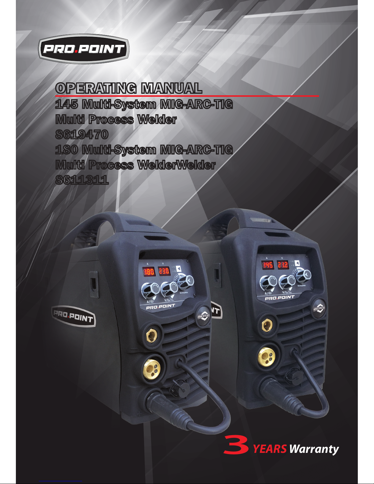
OPERATING MANUAL
145 Multi-System MIG-ARC-TIG
Multi Process Welder
8619470
180 Multi-System MIG-ARC-TIG
Multi Process WelderWelder
8611311
YEARS Warranty
(Power Source)
3
Page 2

2
Thank you for your purchase of your Pro.Point Welding Machine.
We are proud of our range of welding equipment that has a proven track record of innovation, performance
and reliability. Our product range represents the latest developments in Inverter technology put together
by our professional team of highly skilled engineers. The expertise gained from our long involvement with
inverter technology has proven to be invaluable towards the evolution and future development of our equipment range. This experience gives us the inside knowledge on what the arc characteristics, performance
and interface between man and machine should be. Within our team are specialist welders that have a
proven history of welding knowledge and expertise, giving vital input towards ensuring that our machines
deliver control and performance to the utmost professional level. We employ an expert team of professional sales, marketing and technical personnel that provide us with market trends, market feedback and
customer comments and requirements. Secondly they provide a customer support service that is second
to none, thus ensuring our customers have condence that they will be well satised both now and in the
future.
Pro.Point welders are manufactured and compliant with - CAN/CSA E60974-1 &
ANSI/IEC 60974-1, guaranteeing you electrical safety and performance.
WARRANTY
As part of Royal Service, a customer may return a defective unit to any Princess Auto location for a new replacement
unit within 3 years of the purchase date.
Page 3

3
CONTENTS PAGE
Warranty 2, 47
Safety - Cautions 4-6
Technical Data, Product Information for Pro.Point 145 7
Technical Data, Product Information for Pro.Point 180 8
Machine Pro. Point 145/180 Layout 9
Installation & Operation for Pro.Point 145/180 ARC (stick) Welding 10
ARC (Stick) Welding Information 11-12
Installation & Operation for Pro.Point 145/180 MIG Welding with Gas 13-14
Wire Feed Drive Roller Selection 15
Wire Installation for Pro.Point 145/180 Set up Guide 16
Installation & Operation for Gasless MIG Welding for Pro.Point 145/180 17-18
MIG Torch Liner Installation 19
MIG Torch and Wire Feeder Set Up Guide for Aluminum Wire 20-21
Installation & Operation for MIG Welding with Spool Gun 22-23
Basic MIG Welding Guide 24-29
Installation & Operation for DC TIG Welding 30-31
TIG Fusion Technique 32
Tungsten Electrodes & Preparation 33-34
TWECO®2 MIG Welding Torch Parts Breakdown & Spare Parts 35-36
200 AMP Spool Gun Torch Parts Breakdown & Spare Parts 37-38
TIG Torch Parts Breakdown & Spare Parts 39-40
Welding Trouble Shooting Guide 41-45
Spare Parts Identication 46
Warranty/Warranty Exclusions 47
Page 4

4
SAFETY
Welding and cutting equipment can be dangerous to both the operator and people in or near the
surrounding working area, if the equipment is not correctly operated. Equipment must only be
used under the strict and comprehensive observance of all relevant safety regulations.
Read and understand this instruction manual carefully before the installation and operation of this
equipment.
• Do not switch the function modes while the machine is operating. Switching of the function modes during
welding can damage the machine. Damage caused in this manner will not be covered under warranty.
• Disconnect the electrode-holder cable from the machine before switching on the machine, to avoid arcing
should the electrode be in contact with the work piece.
• Operators should be trained and or qualied.
Electric shock: It can kill. Touching live electrical parts can cause fatal shocks or severe
burns. The electrode and work circuit is electrically live whenever the output is on. The input
power circuit and internal machine circuits are also live when power is on. In Mig/Mag welding,
the wire, drive rollers, wire feed housing, and all metal parts touching the welding wire are
electrically live. Incorrectly installed or improperly grounded equipment is dangerous.
• Connect the primary input cable according to United States standards and regulations.
• Avoid all contact with live electrical parts of the welding circuit, electrodes and wires with bare hands.
The operator must wear dry welding gloves while he/she performs the welding task.
• The operator should keep the work piece insulated from himself/herself.
• Keep cords dry, free of oil and grease, and protected from hot metal and sparks.
• Frequently inspect input power cable for wear and tear, replace the cable immediately if damaged,
bare wiring is dangerous and can kill.
• Do not use damaged, under sized, or badly joined cables.
• Do not drape cables over your body.
• We recommend (RCD) safety switch is used with this equipment to detect any leakage of current to earth.
Fumes and gases are dangerous. Smoke and gas generated whilst welding or cutting can
be harmful to people’s health. Welding produces fumes and gases. Breathing these fumes and
gases can be hazardous to your health.
• Do not breathe the smoke and gas generated whilst welding or cutting, keep your head out of the fumes
• Keep the working area well ventilated, use fume extraction or ventilation to remove welding fumes and
gases.
• In conned or heavy fume environments always wear an approved air-supplied respirator.
Welding fumes and gases can displace air and lower the oxygen level causing injury or death.
Be sure the
breathing air is safe.
• Do not weld in locations near de-greasing, cleaning, or spraying operations. The heat and rays of the arc
can react with vapours to form highly toxic and irritating gases.
• Materials such as galvanized, lead, or cadmium plated steel, containing elements that can give off toxic
fumes when welded. Do not weld these materials unless the area is very well ventilated, and or wearing
an air supplied respirator.
Arc rays: harmful to people’s eyes and skin. Arc rays from the welding process produce intense visible
and invisible ultraviolet and infrared rays that can burn eyes and skin.
• Always wear a welding helmet with correct shade of lter lens and suitable protective clothing including
welding gloves whilst the welding operation is performed.
• Measures should be taken to protect people in or near the surrounding working area. Use protective
screens or barriers to protect others from ash,glare and sparks; warn others not to watch the arc.
Machine Operating Safety
Page 5
5
Fire hazard. Welding on closed containers, such as tanks,drums, or pipes, can cause them
to explode. Flying sparks from the welding arc, hot work piece, and hot equipment can cause
res and burns. Accidental contact of electrode to metal objects can cause sparks, explosion,
overheating, or re. Check and be sure the area is safe before doing any welding.
• The welding sparks & spatter may cause re, therefore remove any ammable materials well away from
the working area. Cover ammable materials and containers with approved covers if unable to be moved
from the welding area.
• Do not weld on closed containers such as tanks, drums, or pipes, unless they are properly prepared
according to the required Safety Standards to insure that ammable or toxic vapors and substances are
totally removed, these can cause an explosion even though the vessel has been “cleaned”.
Vent hollow castings or containers before heating, cutting or welding. They may explode.
• Do not weld where the atmosphere may contain ammable dust, gas, or liquid vapours (such as petrol)
• Have a re extinguisher nearby and know how to use it. Be alert that welding sparks and hot materials
from welding can easily go through small cracks and openings to adjacent areas. Be aware that welding
on a ceiling, oor, bulkhead, or partition can cause re on the hidden side.
Gas Cylinders. Shielding gas cylinders contain gas under high pressure. If damaged, a cylinder can explode. Because gas cylinders are normally part of the welding process, be sure to
treat them carefully. CYLINDERS can explode if damaged.
• Protect gas cylinders from excessive heat, mechanical shocks, physical damage, slag, open ames,
sparks, and arcs.
• Insure cylinders are held secure and upright to prevent tipping or falling over.
• Never allow the welding electrode or earth clamp to touch the gas cylinder, do not drape welding cables
over the cylinder.
• Never weld on a pressurised gas cylinder, it will explode and kill you.
• Open the cylinder valve slowly and turn your face away from the cylinder outlet valve and gas regulator.
Gas build up. The build up of gas can causes a toxic environment, deplete the oxygen content
in the air resulting in death or injury. Many gases use in welding are invisible and odourless.
• Shut off shielding gas supply when not in use.
• Always ventilate conned spaces or use approved air-supplied respirator.
Electronic magnetic elds. MAGNETIC FIELDS can affect Implanted Medical Devices.
• Wearers of Pacemakers and other Implanted Medical Devices should keep away.
• Implanted Medical Device wearers should consult their doctor and the device manufacturer before going
near any electric welding, cutting or heating operation.
Noise can damage hearing. Noise from some processes or equipment can damage hearing.
Wear approved ear protection if noise level is high.
Hot parts. Items being welded generate and hold high heat and can cause severe burns.
Do not touch hot parts with bare hands. Allow a cooling period before working on the welding
gun. Use insulated welding gloves and clothing to handle hot parts and prevent burns.
Page 6

6
CAUTION
1. Working Environment.
1.1 The environment in which this welding equipment is installed must be free of grinding dust, corrosive
chemicals, ammable gas or materials etc, and at no more than maximum of 80% humidity.
1.2 When using the machine outdoors protect the machine from direct sun light, rain water and snow etc;
the temperature of working environment should be maintained within 14°Fto .4 to +104°F.
1.3 Keep this equipment 12” distant from the wall.
1.4 Ensure the working environment is well ventilated.
2. Safety Tips.
2.1 Ventilation
This equipment is small-sized, compact in structure, and of excellent performance in amperage output.
The fan is used to dissipate heat generated by this equipment during the welding operation.
Important: Maintain good ventilation of the louvers of this equipment. The minimum distance between
this equipment and any other objects in or near the working area should be 12”. Good ventilation is
of critical importance for the normal performance and service life of this equipment.
2.2 Thermal Overload protection.
Should the machine be used to an excessive level, or in high temperature environment, poorly
ventilated area or if the fan malfunctions the Thermal Overload Switch will be activated and the
machine will cease to operate. Under this circumstance, leave the machine switched on to keep the
built-in fan working to bring down the temperature inside the equipment. The machine will be ready for
use again when the internal temperature reaches safe level.
2.3 Over-Voltage Supply
Regarding the power supply voltage range of the machine, please refer to “Main parameter” table.
This equipment is of automatic voltage compensation, which enables the maintaining of the voltage
range within the given range. In case that the voltage of input power supply amperage exceeds the
stipulated value, it is possible to cause damage to the components of this equipment. Please ensure
your primary power supply is correct.
2.4 Do not come into contact with the output terminals while the machine is in operation. An electric shock
may possibly occur.
MAINTENANCE
Exposure to extremely dusty, damp, or corrosive air is damaging to the welding machine. In order to prevent any possible failure or fault of this welding equipment, clean the dust at regular intervals with clean and
dry compressed air of required pressure.
Please note that: lack of maintenance can result in the cancellation of the guarantee; the guarantee of
this welding equipment will be void if the machine has been modied, attempt to take apart the machine or
open the factory-made sealing of the machine without the consent of an authorized representative of the
manufacturer.
TROUBLE SHOOTING
Caution: Only qualied technicians are authorized to undertake the repair of this welding equipment.
For your safety and to avoid Electrical Shock, please observe all safety notes and precautions
detailed in this manual.
Note:
Minimum Motor Generator Power Suggested: 9.4KVA for MIG210
Page 7
7
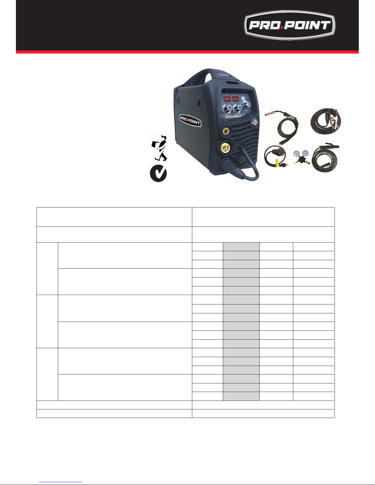
Input voltage Single phase AC230V/115V±15% 50/60Hz
Welding wire diameter
0.025/0.03/0.035(in.)
ARC
Input:115V Rated input current: 21.4A
Output:10A/20.4V 80A/23.2V
X 25% 60% 100%
I2 80A 52A 40A
U2 23.2V 22.1V 21.6V
Input:230V Rated input current: 27A
Output:10A/20.4V 145A/25.8V
X 25% 60% 100%
I2 145A 93.6A 72.5A
U2 25.8V 23.7V 22.9V
MIG
Input:115V Rated input current: 21.4A
Output:30A/15.5V 80A/18V
X 25% 60% 100%
I2 80A 52A 40A
U2 18V 16.6V 16V
Input:230V Rated input current: 22.4A
Output:30A/15.5V 145A/21.2V
X 25% 60% 100%
I2 145A 93.6A 72.5A
U2 21.2V 18.7V 17.6V
TIG
Input:115V Rated input current: 16.5A
Output:10A/10.4V 80A/13.2V
X 25% 60% 100%
I2 80A 52A 40A
U2 13.2V 12.1V 11.6V
Input:230V Rated input current: 16.5A
Output:10A/10.4V 145A/15.8V
X 25% 60% 100%
I2 145A 93.6A 72.5A
U2 15.8V 13.7V 12.9V
Dimensions (in) 19.1x7.3x14.6
Weight Machine (Ibs.) 28
• MIG,TIGANDARCWeldingmachine
• LatestIGBTinvertertechnology
• MIG/MAGwithGasandGaslesswirefunction
• ExcellentMIGweldingwithCO2gas&mixedgas
• EurostyleMIGandTIGtorchconnection
• Internalwirefeederwithsolidconstruction
• AdjustableBurnBack
• SpoolGunConnection
• Steplessvoltageandwirefeedcontrol
• WireInch+SmartSetfunctionality
• Dualvoltage115/230V
• HotStart-AntiStick
• DigitalReadout
• Solidcaseconstruction
• IP21SratingandCSA/CANApproved
Complete with Torch, Regulator, return and ARC lead set and an Adaptor!
ThisnewPro.PointWelderwillprovide145ampsofMIG,TIGandARCoutputforyoutocompleteyourweldingjobs!Idealforthe
DIYenthusiast,thisbeautifullydesignedandhighlyfunctionalmulti-systemisapowerful,portableanddualvoltagemachine
ensuringsmoothandtroublefreeweldingandbackedupbyabig3yearwarranty.OurSmart-setfunctionallowsyoutodialin
yourpreferredwiresizeandgasmixtureandyouarereadytostartwelding!ThemachinecomescompletewithTorch,Regulator,
AdaptorandArcleadset.
25503 74th Ave S Kent WA 98032 USA
Phone: +1 253-859-6277
+1 253-859-6278
FAX: +1 253-859-6286
EMAIL: sales@jasictechamerica.com
sales@razorweld.com
145 Multi-System MIG-ARC-TIG Welder
Part Number: 8619470
Page 8
8
• LatestIGBTinvertertechnology
• MIG/MAGwithGasandGaslesswirefunction
• ExcellentMIGweldingwithCO2gas&mixedgas
• EurostyleMIGandTIGtorchconnection
• Internalwirefeederwithsolidconstruction
• AdjustableBurnBack
• SpoolGunConnection
• Steplessvoltageandwirefeedcontrol
• WireInch+SmartSetfunctionality
• MIG,TIGANDARCWeldingmachine
• Dualvoltage115/230V
• HotStart-AntiStick
• DigitalReadout
• Solidcaseconstruction
• IP21SratingandCSA/CANApproved
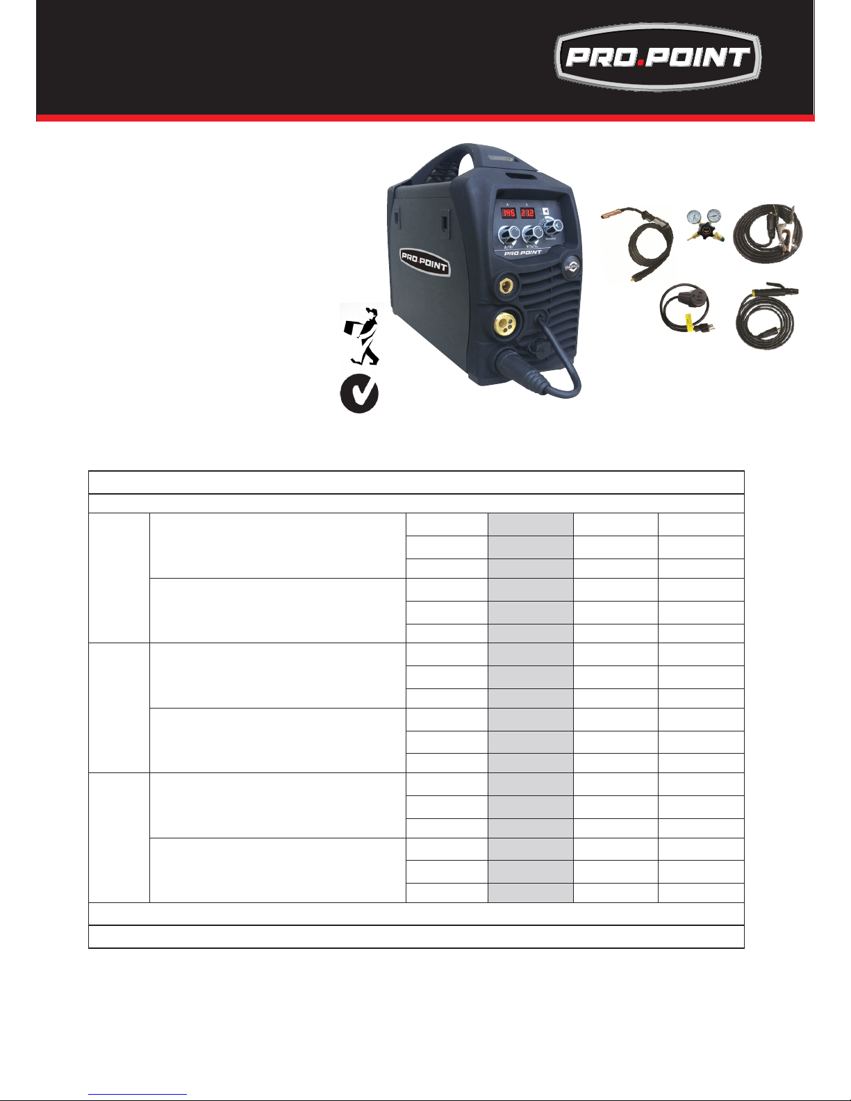
CompletewithTorch,Regulator,returnandARCleadsetandAdaptor!
Dual Voltage
ThisnewPro.PointWelderwillprovide180ampsofMIG,TIGandARCoutputforyoutocompleteyourweldingjobs!Idealforthe
serioustradesman,thisbeautifullydesignedandhighlyfunctionalmulti-systemisapowerful,portableanddualvoltagemachine
ensuringsmoothandtroublefreeweldingandbackedupbyabig3yearwarranty.OurSmart-setfunctionallowsyoutodialinyour
preferredwiresizeandgasmixtureandyouarereadytostartwelding!ThemachinecomescompletewithTorch,Regulator,Adaptor
andArcleadset.ArealworkhorsewithahightdutyCycle!
Input voltage(V) Single phase AC230V/115V±15%(50/60Hz)
Welding wire diameter 0.025/0.03/0.035(in.)
ARC
Input:115V-20A Rated input current: 27.5A
Output:10A/20.4V~100A/24V
X 25% 60% 100%
I2 100A 65A 50A
U2 24V 22.6V 22V
Input:230V Rated input current: 30A
Output:10A/20.4V~160A/26.4V
X 25% 60% 100%
I2 160A 103A 80A
U2 26.4V 24.1V 23.6V
MIG
Input:115V-15A Rated input current: 21.4A
Output:30A/15.5V~100A/19V
X 25% 60% 100%
I2 100A 65A 50A
U2 19V 17.3V 16.5V
Input:230V R ated input current: 30.2A
Output:30A/15.5V~180A/21.5V
X 25% 60% 100%
I2 180A 116A 90A
U2 23V 19.8V 18.5V
TIG
Input:115V R ated input current: 21.4A
Output:10A/10.4V~100A/14V
X 25% 60% 100%
I2 100A 65A 50A
U2 14V 12.6V 12V
Input:230V Rated input current: 22.6A
Output:10A/10.4V~180A/17.2V
X 25% 60% 100%
I2 180A 116A 90A
U2 17.2V 14.6V 13.6V
Dimensions (in.) 19.1×7.3×14.6
Weight 28.4 Pounds (Machine)
180 Multi-System MIG-ARC-TIG Welder
Part Number: 8611311
Page 9
9
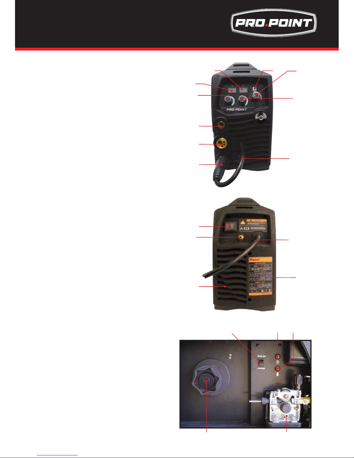
FRONT PANEL LAYOUT
1. Digital Volts Meter
2. Digital Amps Meter
3. 2T/4T Selector Button
4. Wire Speed / AmpsAdjustment Knob
5. Voltage / Downslope /ARC Force Adjustment Knob
6. MIG / TIG / MMA /Smartset Selector Knob
7. “-” Output terminal
8. Euro MIG / TIG Torch Connector (MIG/MAG)
9. “+” Output terminal
10. SpoolGun Power Supply Connection
BACK PANEL LAYOUT
11. Power switch
12. Gas Inlet
13. Fan
14. Input power cable
15. Data Plate
14
12
15
11
INTERNAL PANEL LAYOUT
16. Spoolgun/Standard selector switch
17. Inch wire feed button
18. Gas Check button
19. Spool holder assembly
20. Geared Wire feed assembly
17
20
19
13
18
16
1
2
3 6
5
4
7
8
9
10
Front, Back, & Internal Panel Layout for Pro.
Point145 & 180
Page 10
10
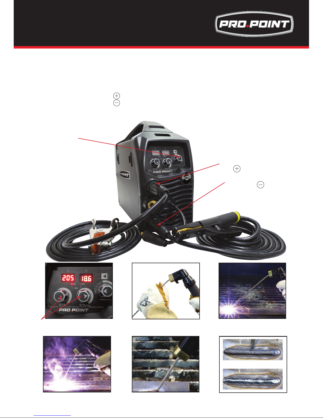
(1) Connect the
electrode lead to
(2) Set MIG/TIG/ARC selector
switch to MMA
(1) Connect the earth
lead to
1) Connection of Output Cables
Two sockets are available on this welding machine. For ARC welding the electrode holder is shown
be connected to the negative socket, while the earth lead (work piece) is connected to the positive
socket, this is known as DC- polarity. However various electrodes require a different polarity for
optimum results and careful attention should be paid to the polarity, refer to the electrode
manufacturers information for the correct polarity.
DC+ Electrode connected to output socket.
DC- Electrode connected to output socket.
(2) Turn the power source on and select the ARC function with the MIG/TIG/ARC selector switch.
(3) Set the welding current relevant to the electrode type and size being used as recommended by the
electrode manufacturer.
(3) Set the welding current using the amperage
control dial. and adjust arcforce if required
(6) Hold the electrode slightly above the work
maintaining the arc while travelling at an even
speed.
(4) Place the electrode into the electrode holder
and clamp tight.
(7) To nish the weld, break the arc by quickly
snapping the electrode away from the work
piece.
(5) Strike the electrode against the workpiece to
create an arc and hold the electrode steady to
maintain the arc.
(8) Wait for the weld to cool and carefully chip
away the slag to reveal the weld metal below.
Installation & Operation for ARC (Stick)
Welding for Pro.Point 145 & 180
Page 11
11
ARC Welding
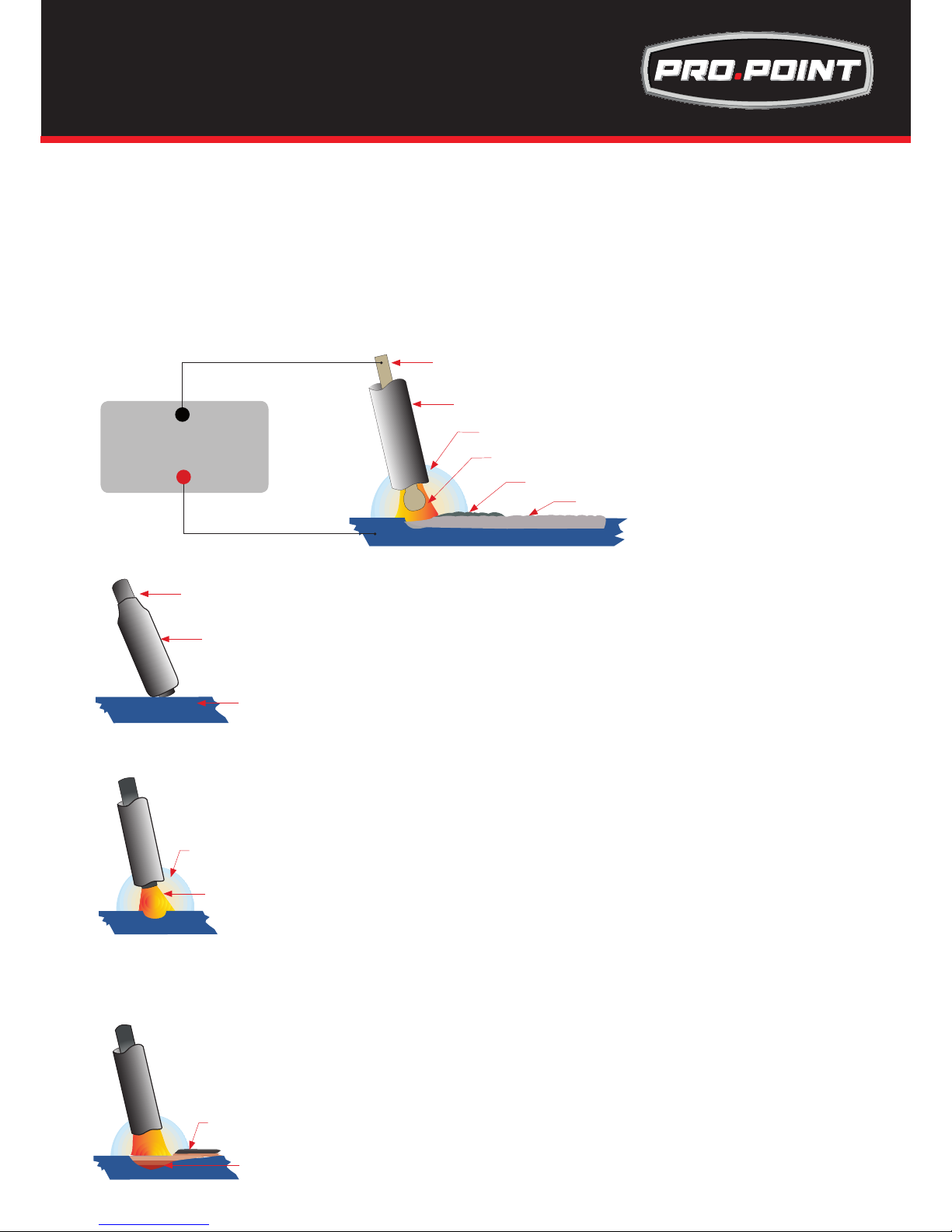
One of the most common types of arc welding is manual metal arc welding (MMA) or stick welding. An electric cur-
rent is used to strike an arc between the base material and a consumable electrode rod or ‘stick’. The electrode rod
is made of a material that is compatible with the base material being welded and is covered with a ux that gives off
gaseous vapours that serve as a shielding gas and providing a layer of slag, both of which protect the weld area from
atmospheric contamination. The electrode core itself acts as ller material the residue from the ux that forms a slag
covering over the weld metal must be chipped away after welding.
Core wire
Flux coating
Gas shield from ux melt
Arc with core wire melt
Flux residue forms slag cover
Weld metal
Power Source
+
▬
• The arc is initiated by momentarily touching the electrode to the base metal.
• The heat of the arc melts the surface of the base metal to form a molten pool
at the end of the electrode.
• The melted electrode metal is transferred across the arc into the molten pool
and becomes the deposited weld metal.
• The deposit is covered and protected by a slag which comes from the
electrode coating.
• The arc and the immediate area are enveloped by an atmosphere of
protective gas
Core wire
Flux coating
Base metal
Protective gas
Arc
Slag
Weld pool
Manual metal arc ( stick) electrodes have a solid metal wire core and a ux
coating. These electrodes are identied by the wire diameter and by
a series of letters and numbers. The letters and numbers identify the metal
alloy and the intended use of the electrode.
The Metal Wire Core works as conductor of the current that maintains the arc.
The core wire melts and is deposited into the welding pool.
The covering on a shielded metal arc welding electrode is called Flux.
The ux on the electrode performs many different functions.
These include:
● producing a protective gas around the weld area
● providing uxing elements and deoxidizers
● creating a protective slag coating over the weld as it cools
● establishing arc characteristics
● adding alloying elements.
Covered electrodes serve many purposes in addition to adding ller metal to
the molten pool. These additional functions are provided mainly by the covering on the electrode.
ARC (Stick) Welding Information
Page 12
12
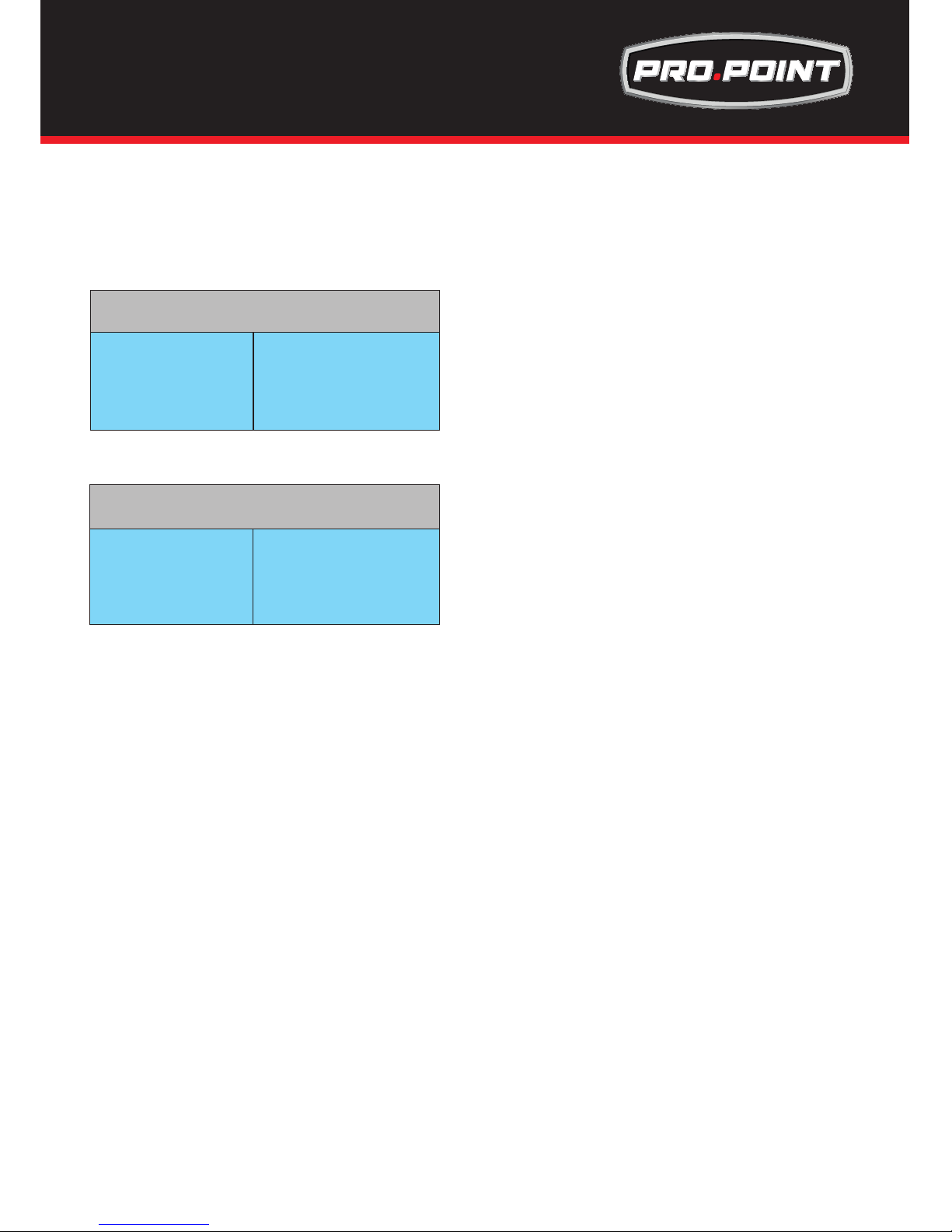
Electrode Size
Average Thickness Maximum Recommended
of Material Electrode Diameter
0.03 - 0.07 inches 0.09 inches
0.07 - 0.19 inches 0.12 inches
0.19 - 0.31 inches 0.15 inches
0.31 - > inches 0.19 inches
The size of the electrode generally depends on the
thickness of the section being welded, and the thicker
the section the larger the electrode required. The table
gives the maximum size of electrodes that maybe used
for various thicknesses of section based on using a
general purpose type 6013 electrode.
Correct current selection for a particular job is an
important factor in arc welding. With the current set too
low, difculty is experienced in striking and maintaining
a stable arc. The electrode tends to stick to the work,
penetration is poor and beads with a distinct rounded
prole will be deposited. Too high current is
accompanied by overheating of the electrode resulting
undercut and burning through of the base metal and
producing excessive spatter. Normal current for a particular job may be considered as the maximum, which
can be used without burning through the work, over-heating the electrode or producing a rough spattered
surface.The table shows current ranges generally recommended for a general purpose type 6013
electrode.
Arc Length
To strike the arc, the electrode should be gently scraped on the work until the arc is established. There is a
simple rule for the proper arc length; it should be the shortest arc that gives a good surface to the weld. An
arc too long reduces penetration, produces spatter and gives a rough surface nish to the weld.
An excessively short arc will cause sticking of the electrode and result in poor quality welds. General rule of
thumb for down hand welding is to have an arc length no greater than the diameter of the core wire.
Electrode Angle
The angle that the electrode makes with the work is important to ensure a smooth, even transfer of metal.
When welding in down hand, llet, horizontal or overhead the angle of the electrode is generally between 5
and 15 degrees towards the direction of travel. When vertical up welding the angle of the electrode should
be between 80 and 90 degrees to the work piece.
Travel Speed
The electrode should be moved along in the direction of the joint being welded at a speed that will give the
size of run required. At the same time, the electrode is fed downwards to keep the correct arc length at all
times. Excessive travel speeds lead to poor fusion, lack of penetration etc, while too slow a rate of travel
will frequently lead to arc instability,slag inclusions and poor mechanical properties.
Material and Joint Preparation
The material to be welded should be clean and free of any moisture, paint, oil, grease, mill scale, rust or
any other material that will hinder the arc and contaminate the weld material. Joint preparation will depend
on the method used include sawing, punching, shearing, machining, ame cutting and others. In all cases
edges should be clean and free of any contaminates. The type of joint will be determined by the chosen
application.
Welding Current (Amperage)
Electrode Size Current Range
ø mm (Amps)
0.09 inches 60 - 100
0.12 inches 100 - 130
0.15 inches 130 - 165
0.19 inches 165 - 260
Electrode Selection
As a general rule, the selection of an electrode is straight forward,in that it is only a matter of selecting an
electrode of similar composition to the parent metal. However, for some metals there is a choice of several
electrodes, each of which has particular properties to suit specic classes of work. It is recommend to
consult your welding supplier for the correct selection of electrode.
ARC Welding Fundamentals
Page 13
13
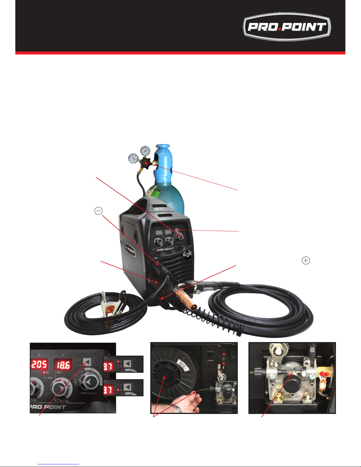
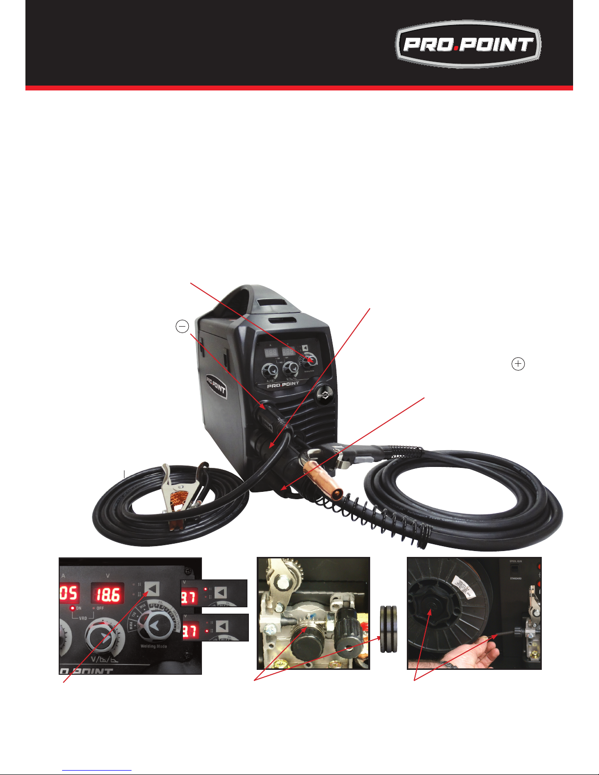
(7) Place wire onto spool holder - (spool retaining
nut is left hand thread ) Feed the wire through the
inlet guide tube on to the drive roller.
(3) Connect weld power lead to
(8) Feed wire over the drive roller into
the outlet guide tube, Push the wire
through approx 4-5in.
(2) Connect earth lead to
(5) Set torch operation 2T / 4T
IMPORTANT : When connecting the torch
be sure to tighten the connection.
(1) Connect MIG torch
(5) Select torch operation 2T or 4T
(1) Connect Mig Torch IMPORTANT : When connecting the torch be sure to tighten the connection.
(2) Connect the earth lead to Negative socket
(3) Connect the weld power lead to Positive socket
(4) Turn the power source on and select the MIG function with the MIG/TIG/MMA selector switch.
Or Select Smartset is a predefined setting based on Gas and wire used. The machine will preselect
Voltage and wire speed allowing the user to quickly find the best welding parameters for a given metal.
(5) Set torch operation 2T / 4T.
• When 2T operation is selected press trigger Arc starts, release trigger, Arc stops.
burnback operation is automatic and preset.
• When 4T operation is selected press and release trigger Arc starts, press and release trigger Arc stops.
burnback operation is automatic and preset.
(6) Connect the gas line to the regulator
and connect to the gas cylinder
WARNING:
Disconnect the Electrode Holder cable from the machine before using MIG function. If cable is not disconnected welding
voltage is present and can cause arcing or ash.
WARNING:
Ensure that an approved welding helmet, protective clothing and gloves are use for all welding operations
(4) Set MIG/TIG/MMA selector
switch to MIG
OR Select SMARTSET
Installation & Operation for MIG with Gas for
Pro.Point 145 & 180
Page 14
14
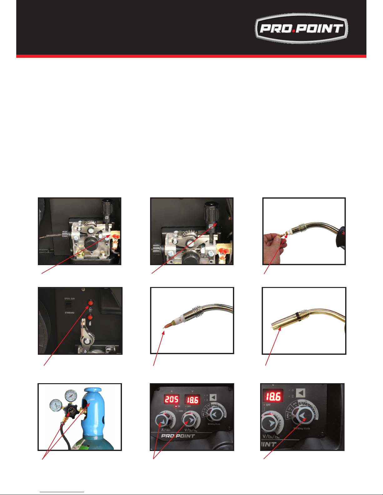
(7) Place wire onto spool holder - (spool retaining nut is left hand thread )
Feed the wire through the inlet guide tube on to the drive roller.
(8) Feed wire over the drive roller into the outlet guide tube, Push the wire through approx 3-4in
(9) Align the wire into the groove of the drive roller and close down the top roller making sure the wire is in
the groove of the bottom drive roller, lock the pressure arm into place.
(10) Apply a medium amount of pressure to the drive roller.
(11) Remove the gas nozzle and contact tip from the torch neck,
(12) Press and hold the inch button to feed the wire through to the torch neck, release the inch button when
the wire exits the torch neck.
(13) Fit the correct sized contact tip and feed the wire through it,
screw the contact tip into the tip holder of the torch head and nip it up tightly.
(14) Fit the gas nozzle to the torch head.
(15) Carefully open the gas cylinder valve and set the ow rate to between 11-21cfh.
(16) Set the welding parameters using the wire feed and voltage control knobs.
(17) Or use Smartset, Smartset is a predefined setting based on Gas and wire used.
The machine will preselect Voltage and wire speed allowing the user to quickly find the best welding parameters for a given metal.
(12) Press and hold the inch wire button to
feed the wire down the torch cable through
to the torch head.
(11) Remove the gas nozzle and contact tip
from the front end of the mig torch.
(13) Fit the correct size contact tip over
the wire and fasten tightly into the tip
holder.
(14) Fit the gas nozzle to the torch head.
(16) Set welding parameters using the
voltage and wire feed controls.
(17) Smartset is a predefined setting based
on Gas and wire used. The machine will
preselect Voltage and wire speed allowing
the user to quickly find the best welding
parameters for a given metal.
(9) Close down the top roller bracket and clip
the pressure arm into place.
(10) Apply a medium amount of
pressure to the drive roller
(15) Carefully open the valve of the gas
cylinder, set the ow to 21cfh
Installation & Operation for MIG with Gas for
Pro.Point 145 & 180
Page 15
15
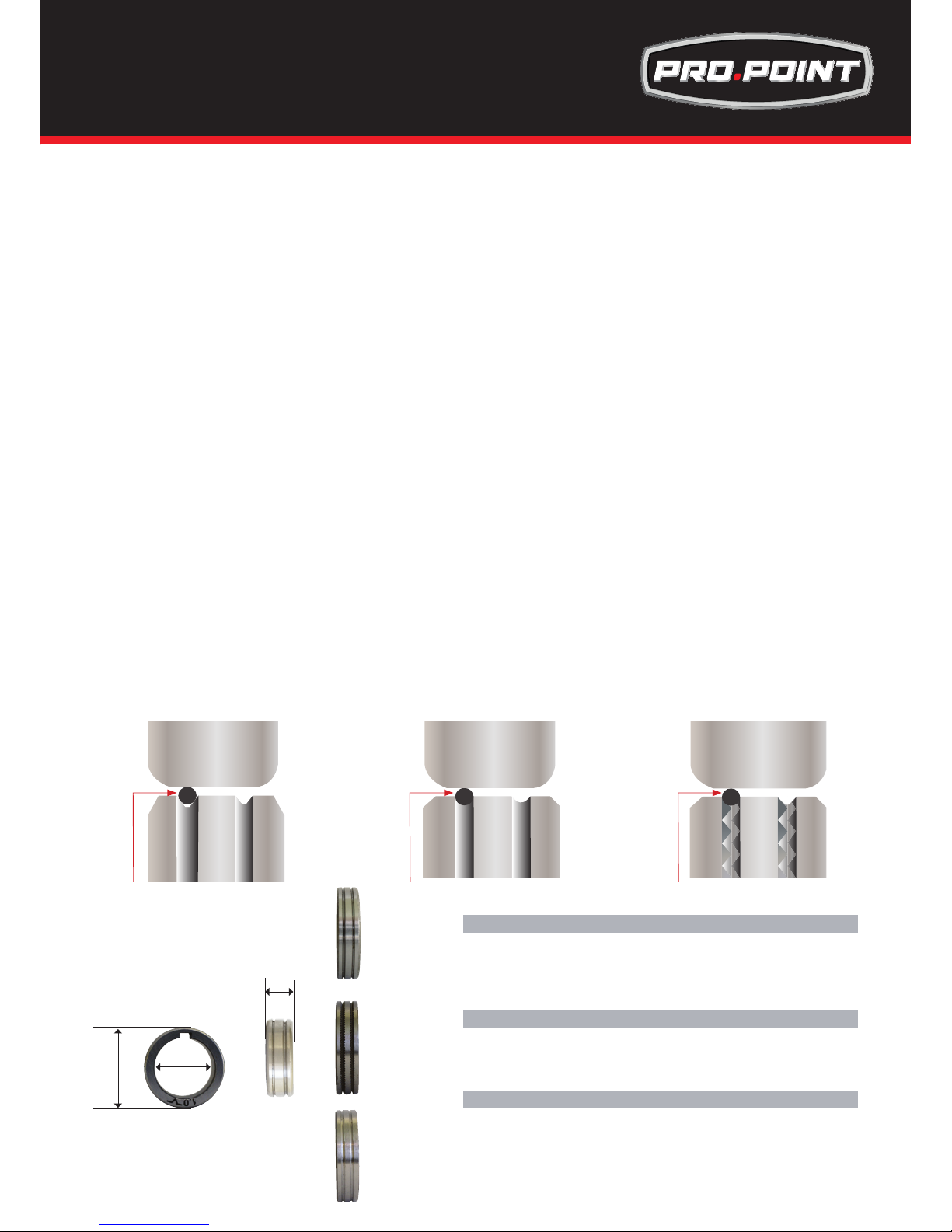
Drive Rollers
The importance of smooth consistent wire feeding during MIG welding cannot be emphasized enough.
Simply put the smoother the wire feed then the better the welding will be.
Feed rollers or drive rollers are used to feed the wire mechanically along the length of the welding gun.
Feed rollers are designed to be used for certain types of welding wire and they have different types of
grooves machined in them to accommodate the different types of wire. The wire is held in the groove by
the top roller of the wire drive unit and is referred to as the pressure roller, pressure is applied by a tension
arm that can be adjusted to increase or decrease the pressure as required. The type of wire will determine
how much pressure can be applied and what type of drive roller is best suited to obtain optimum wire feed.
Solid Hard Wire - like Steel, Stainless Steel require a drive roller with a V shape groove for optimum grip
and drive capability. Solid wires can have more tension applied to the wire from the top pressure roller that
holds the wire in the groove and the V shape groove is more suited for this. Solid wires are more forgiving
to feed due to their higher cross sectional column strength, they are stiffer and don’t bend so easy.
Soft Wire - like Aluminium requires a U shape groove. Aluminium wire has a lot less column strength, can
bend easily and is therefore more difcult to feed. Soft wires can easily buckle at the wire feeder where the
wire is fed into inlet guide tube of the torch. The U-shaped roller offers more surface area grip and traction
to help feed the softer wire. Softer wires also require less tension from the top pressure roller to avoid deforming the shape of the wire, too much tension will push the wire out of shape and cause it to catch in the
contact tip.
Flux Core / Gasless Wire - these wires are made up of a thin metal sheath that has uxing and metal
compounds layered onto it and then rolled into a cylinder to form the nished wire. The wire cannot take
too much pressure from the top roller as it can be crushed and deformed if too much pressure is applied.
A knurled drive roller has been developed and it has small serrations in the groove, the serrations grip the
wire and assist to drive it without too much pressure from the top roller. The down side to the knurled wire
feed roller on ux cored wire is it will slowly over time bit by bit eat away at the surface of the welding wire,
and these small pieces will eventually go down into the liner. This will cause clogging in the liner and added
friction that will lead to welding wire feed problems. A U groove wire can also be used for ux core wire
without the wire particles coming of the wire surface. However it is considered that the knurled roller will
give a more positive feed of ux core wire without any deformation of the wire shape.
V Groove U Groove Knurled Groove
Wire Wire Wire
Top Pressure Roller Top Pressure Roller Top Pressure Roller
22mm
30mm
10mm
V Groove Drive Roller - Steel Wire
Drive Roll V Groove 0.6-0.8mm
Drive Roll V Groove 0.8-1.0mm
Drive Roll V Groove 0.9-1.2mm
Drive Roll V Groove 1.0-1.2mm
Drive Roll V Groove 1.2-1.6mm
Knurled Drive Roller - Flux Core Wire
Drive Roll Knurled 0.6-0.9mm
Drive Roll Knurled 0.8-0.9mm
Drive Roll Knurled 0.9-1.2mm
Drive Roll Knurled 1.2-1.6mm
U Groove Drive Roller - Soft Wire
Drive Roll U Groove 1.0-1.2mm
Drive Roll U Groove 0.9-1.0mm
Drive Roll U Groove 0.9-1.2mm
Drive Roll U Groove 1.0-1.2mm
Wire Feed Roller Selection for
Pro.Point 145 & 180
Page 16
16
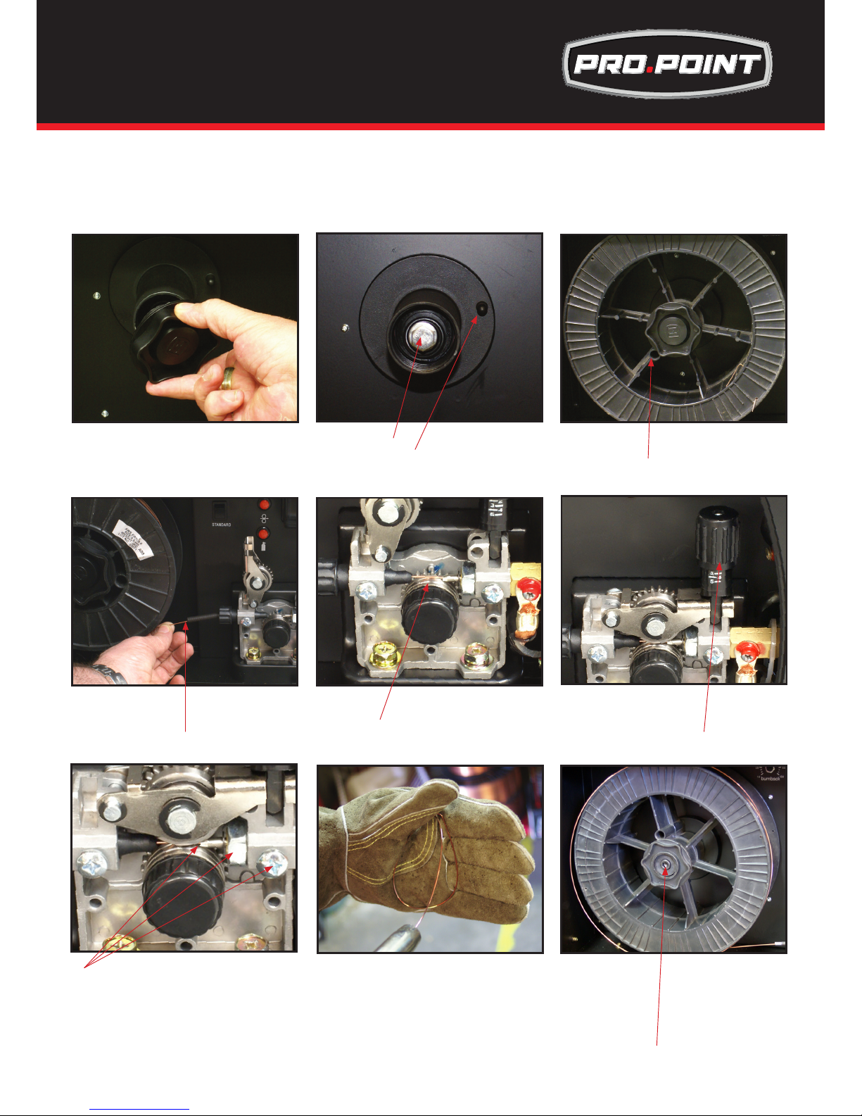
Again the importance of smooth consistent wire feeding during MIG welding cannot be emphasized enough.
The correct installation of the wire spool and the wire into the wire feed unit is critical to achieving an even
and consistent wire feed. A high percentage of faults with mig welders emanate from poor set up of the wire
into the wire feeder. The guide below will assist in the correct setup of your wire feeder.
(1) Remove the spool retaining nut.
(3) Fit the wire spool onto the spool holder
tting the locating pin into the location hole
on the spool. Replace the spool retaining
nut tightly
(2) Note the tension spring adjuster
and spool locating pin.
(7) Check that the wire passes through
the centre of the outlet guide tube without
touching the sides. Loosen the locking
screw and then loosen the outlet guide
tube retaining nut too make adjustment if
required. Carefully retighten the locking nut
and screw to hold the new position.
NOTE: MIG 180-145 not geared
(4) Snip the wire carefully, be sure to hold the
wire to prevent the spool uncoiling. Carefully
feed the wire into the inlet guide tube of the
wire feed unit.
(5) Feed the wire through the drive roller and
into the outlet guide tube of the wire feeder.
NOTE: MIG 180-145 not geared
(6) Lock down the top pressure roller and
apply a medium amount of pressure using the tension adjustment knob
NOTE: MIG 180-145not geared
(8) A simple check for the correct drive tension
is to bend the end of the wire over hold it about
4in
from your hand and let it run into your hand, it
should coil round in your hand without stopping
and slipping at the drive rollers, increase the
tension if it slips.
(8) The weight and speed of the wire spool
turning creates an inertia that can cause the
spool to run on and the wire loop over the
side of the spool and tangle. if this happens
increase the pressure on the tension spring
inside the spool holder assembly using the
tension adjustment screw.
Wire Installation and Set Up Guide for
Pro.Point 145 & 180
Page 17
17
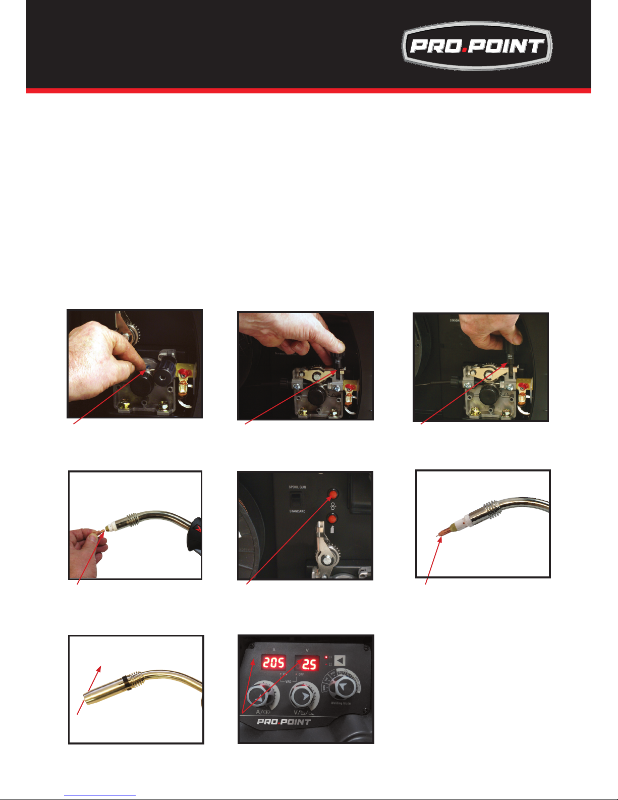
(3) Connect weld power lead to
(7) Place wire onto spool holder - (spool
retaining nut is left hand thread ) Feed
the wire through the inlet guide tube on
to the drive roller.
(6) Fit the correct sized Knurled Drive
roller for Gas Less Flux Cored wire
(2) Connect earth lead to
(4) Set MIG/TIG/MMA selector
switch to MIG
IMPORTANT : When connecting the torch
be sure to tighten the connection.
(1) Connect MIG torch
(1) Connect Mig Torch
IMPORTANT: When connecting the torch be sure to tighten the connection. Additionally Digital MIG
torch must be connected prior to power being turned on otherwise remote control will not work
(2) Connect the earth lead to Positive socket
(3) Connect the weld power lead to Negative socket
(4) Turn the power source on and select the MIG function with the MIG/TIG/MMA selector switch.
(5) Set torch operation 2T / 4T.
• When 2T operation is selected press trigger Arc starts, release trigger, Arc stops.
burnback operation is automatic and preset.
• When 4T operation is selected press and release trigger Arc starts, press and release trigger Arc stops.
burnback operation is automatic and preset..
(6) Fit the correct size Knurled drive roller for Gas Less Flux Core wire.
(5) Select torch operation 2T or 4T
WARNING:
Disconnect the Electrode Holder cable from the machine before using MIG function. If cable is not disconnected welding
voltage is present and can cause arcing or ash.
WARNING:
Ensure that an approved welding helmet, protective clothing and gloves are use for all welding operations
t
Installation & Operation for Gasless MIG for
Pro.Point 145 & 180
Page 18
18
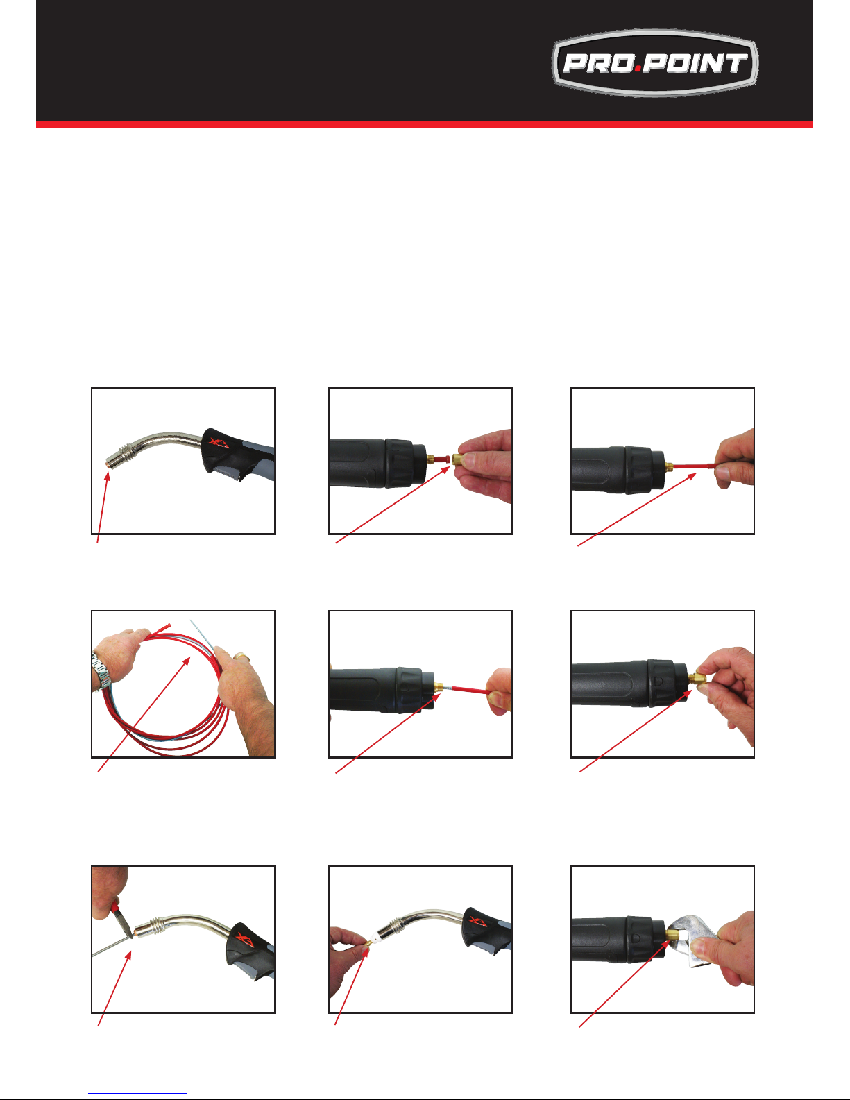
(7) Place the Wire Spool onto the Spool Holder - Note: the spool retaining nut is Left Hand thread.
Snip the wire from the spool being sure to hold the wire to prevent rapid uncoiling. Feed the wire into
the wire feeder inlet guide tube through to the drive roller.
(8) Carefully feed the wire over the drive roller into the outlet guide tube, feed through about 8-9in into
the torch receptacle. .
(9) Align the wire into the groove of the drive roller and close down the top roller making sure the wire is in
the groove of the bottom drive roller, lock the pressure arm into place.
(10) Apply a light amount of pressure to the drive roller. Too much pressure will crush the cored wire.
(11) Remove the gas nozzle and contact tip from the torch neck,
(12) Press and hold the inch button to feed the wire through to the torch neck, release the inch button when
the wire exits the torch neck.
(13) Fit the correct sized contact tip and feed the wire through it, screw the contact tip into the tip holder of
the torch head and nip it up tightly.
(14) Fit the gas nozzle to the torch head.
(15) Set the welding parameters using the wire feed and voltage control knobs.
(15) Set welding parameters using the
voltage and wire feed controls.
(10) Apply a medium amount of
pressure to the drive roller
(14) Fit the gas nozzle to the torch head.
(9) Close down the top roller bracket and clip
the pressure arm into place.
(11) Remove the gas nozzle and contact tip
from the front end of the mig torch.
(12) Press and hold the inch wire button to
feed the wire down the torch cable through
to the torch head.
(13) Fit the correct size contact tip over
the wire and fasten tightly into the tip
holder.
(8) Feed wire over the drive roller into
the outlet guide tube, Push the wire
through approx 8-9in. Use a Knurled
Drive Roller of the correct size
t
Installation & Operation for Gassless MIG for
Pro.Point 145 & 180
Page 19
19
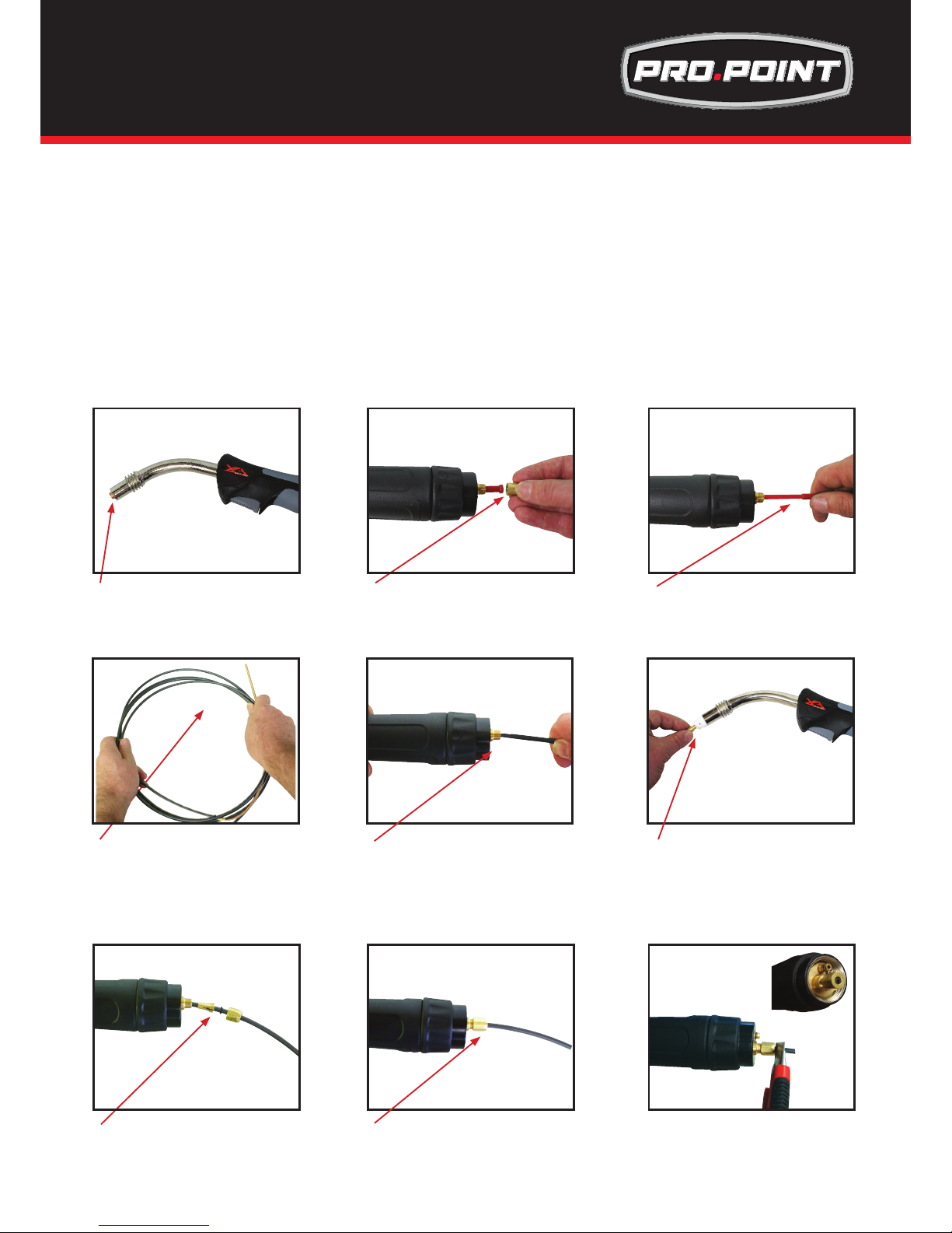
(1) Lay the torch out straight on the ground and remove the front end parts
(2) Remove the liner retaining nut.
(3) Carefully pull the liner out of the torch cable assembly
(4) Select the correct new liner and carefully unravel avoiding putting any kinks in the liner, if you kink the
liner it will make it no good and will require replacement.
(5) Carefully and slowly feed the liner in short forward movements down the cable assembly all the way
through and out the torch neck end. Avoid kinking the liner, kinking liner it will make it no good and
require replacement.
(6) Fit the liner retaining nut and screw down only 1/2 way
(7) Leaving the torch straight snip the liner approximately 1/8in past the end of the torch neck
(8) Place the tip holder over the end of the liner and screw into the torch neck trimming it up tight.
(9) Screw down the liner nut the remaining 1/2 and trim it up tight. This method compresses the liner
inside the torch cable assembly preventing it moving during use and ensures good wire feed.
(2) Remove the liner retaining nut (3) Carefully pull out and completely
remove the liner
(4) Carefully unravel the new liner
(8) Replace the front end parts
(5) Carefully feed in the new liner down
the torch lead all the way to exit the torch
neck.
(9) Fully screw down the liner retaining
nut and nip it up tight.
(6) Fit the liner retaining nut and screw
only 1/2 way down
(1) Remove mig torch front end parts
(7) Snip the liner off 3mm past the end
of the torch neck.
t
MIG Torch Liner Installation for
Pro.Point 145 & 180
Page 20
20
(1) Lay the torch out straight on the ground and remove the front end parts
(2) Remove the liner retaining nut.
(3) Carefully pull the liner out of the torch cable assembly
(4) Select a PA or liner, carefully and slowly feed the liner in short forward movements down the cable
assembly all the way through and out the torch neck end. Avoid kinking the liner, kinking the liner will
ruin it and require replacement.
(5) Leave the liner extending out the end of the torch neck end by 1/8in
(5) Fit the liner retaining nut together with the liner o-ring.
8) Push the liner rmly into the torch lead and tighten the liner retaining nut.
(9) Install a U groove drive roller of the correct size to match the wire diameter being used.
(2) Remove the liner retaining nut (3) Carefully pull out and completely
remove the liner
(4) Carefully unravel the new liner
(8) Push the liner rmly into the torch lead
and tighten the liner retaining nut
(5) Carefully feed in the new liner in short
forward movements down the torch lead
all the way to exit the torch neck. Be careful not to kink the liner
(9) Cut the liner ush with the end of
liner retaining nut using a sharp box cutter knife.
(6) Replace the front end parts
(1) Remove mig torch front end parts
(7) Fit the liner collet, liner O-ring and
liner retaining nut.
Torch & Wire Feed Set Up for Aluminium Wire
for Pro.Point 145 & 180
t
Page 21
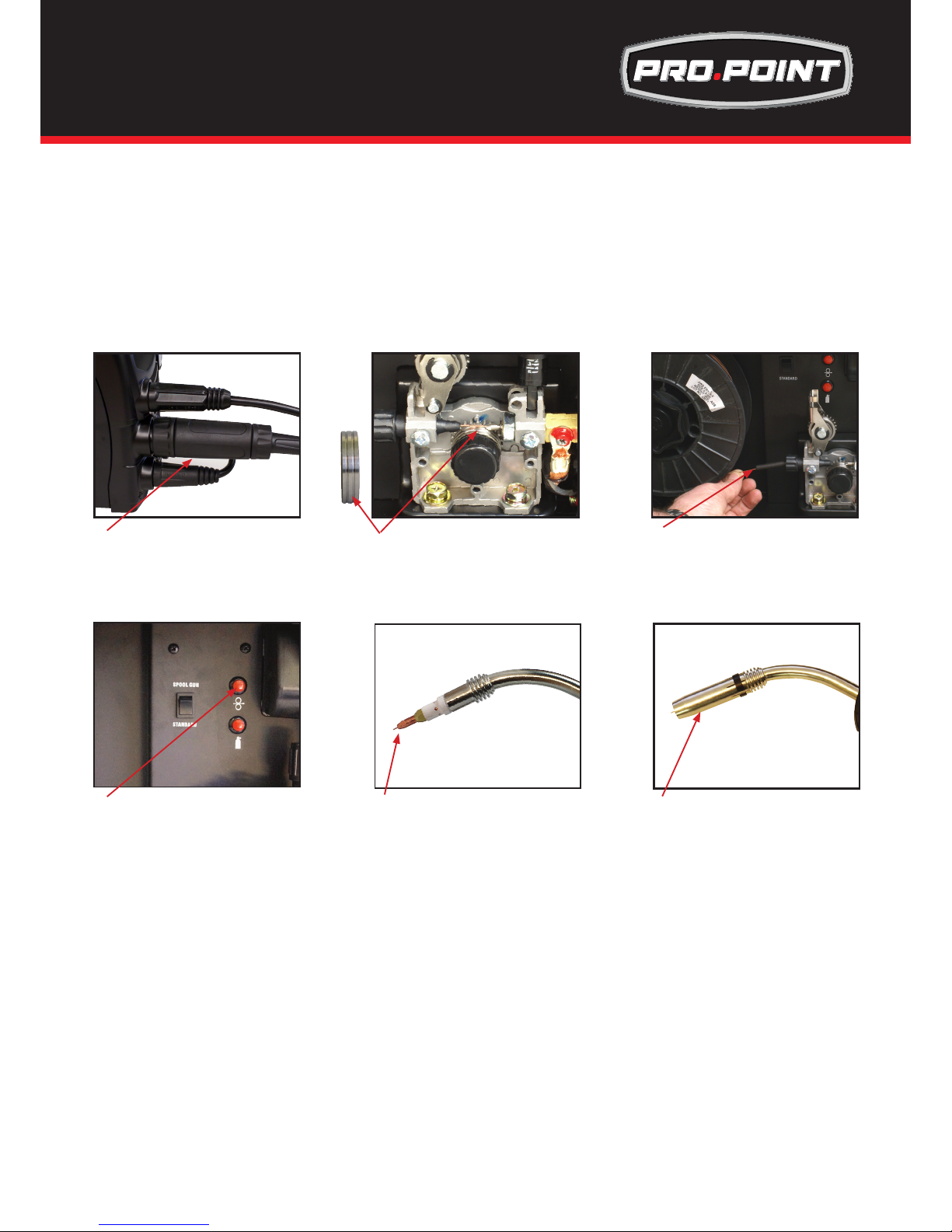
21
(10) Loosen off the inlet guide tube retaining screw
(11) Remove the inlet guide tube from the front end machine euro connector using long nose pliers.
(12) Carefully feed the extended PA liner section into the inlet guide tube hole of the machine euro
connector
(13) Feed the extended PA liner all the way up and over the drive roller
(14) Tighten the torch euro connection to the machine euro connector
(15) Cut the extended liner with a sharp razor knife just in front of the drive roller
(16) Fit an Aluminum contact tip of the correct size to match the diameter of the wire being used
(17) Fit the remaining front end parts to the torch neck ready for welding
(17) Fit the remaining front end parts to the
torch neck ready for welding.
(11) Install a U groove drive roller of the
correct size for the diameter wire being used.
NOTE: MIG 180-145not geared
(7) Place aluminum wire onto spool
holder. Feed the wire through the inlet
guide tube on to the drive roller.
NOTE: MIG 180-145 not geared
(10)Connect the torch to the machine
tighten and secure the torch euro connector to the machine euro connection.
(16) Fit an Aluminium contact tip of the
correct size to match the wire diameter
being used
(12) Press and hold the inch wire button to
feed the wire down the torch cable through to
the torch head.
Torch & Wire Feed Set Up for Aluminium Wire
for Pro.Point 145 & 180
Page 22
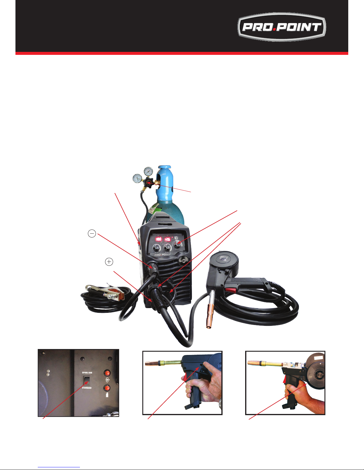
22
(1) Select Spool Gun using the Standard/Spool Gun selector switch.
(2) Connect the Spool Gun to the Euro MIG torch connection socket on the front panel, and tighten it.
Connect the Spool Gun control cable to the receptacle and tighten it.
IMPORTANT : When connecting the torch be sure to tighten the connection. A loose connection can
result in the connector arcing and damaging the machine and gun connector.
This damage is not covered under warranty.
(3) Insert the earth cable plug into the Negative socket on the front of the machine and tighten it.
(4) Connect weld power lead to Positive socket
(5) Connect Gas Line to Gas Regulator and connect the gas regulator to the Gas Cylinder.
(6) Turn the power source on and select the MIG function with the MIG/TIG/MMA selector switch.
(7) Take the Spool Gun and push the Cover Release Button to unlock the wire feed / spool cover.
(8) Place the Wire Spool onto the Spool Holder - Note: the spool retaining nut is Left Hand thread.
Hold and snip the wire from the spool being sure to hold the wire to prevent rapid uncoiling.
(3) Connect earth lead to
(1) Set Standard/Spoolgun
selector switch inside door
to Spoolgun
(5) Connect the gas line to the regulator
and connect to the gas cylinder
(6) Set MIG/TIG/MMA selector
switch to MIG
IMPORTANT : When connecting the torch
be sure to tighten the connection.
(2) Connect Spool Gun to Euro connection
Connect the Spool Gun control cable to the
receptacle
(4) Connect weld power lead to
Remove wire from the drive unit
(8) Place a spool of wire onto the Spool
holder. Note: the spool retaining nut is Left
Hand thread, turn it clockwise to undo it
(7) Push the cover release button to
unlock the wire feed /spool cover
(1) Set Standard/Spoolgun
selector switch inside door to Spoolgun
WARNING:
Disconnect the Electrode Holder cable from the machine before using MIG function. If cable is not disconnected welding
voltage is present and can cause arcing or ash.
WARNING:
Ensure that an approved welding helmet, protective clothing and gloves are use for all welding operations
Installation & Operation of the Spool Gun for
Pro.Point 145 &180
Page 23
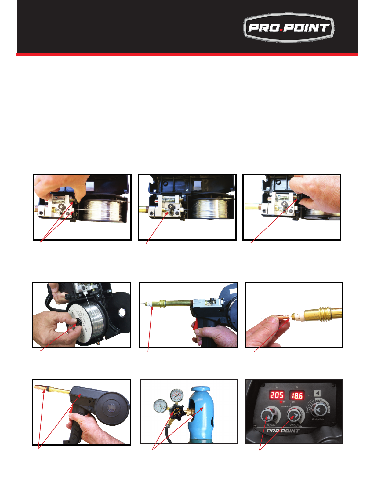
23
(9) Carefully feed the wire over the drive roller into the outlet guide tube, feed through into the torch neck.
Check that the drive roller being used complies with the wire diameter, replace the roller if necessary.
(10) Align the wire into the groove of the drive roller and release the tension arm making sure the wire is
in the groove of the drive roller.
(11) Apply a adepuate amount of pressure to the drive roller by winding in the tension adjusting knob,
(12) Adjust spool hoder tension
(13) Remove the gas nozzle and contact tip from the torch neck, Pull the trigger to drive the wire through
the neck until it exits the contact tip holder
(14) Fit the correct sized contact tip and feed the wire through it, screw the contact tip into the tip holder of
the torch neck and nip it up tightly.
(15) Fit the gas nozzle to the torch head and close the wire spool cover.
(16) Carefully open the gas cylinder valve and set the ow rate to between 21-30cfh.
(17) Set the welding parameters using the wire feed and voltage control knobs.
(9) Carefully feed the wire through the inlet
guide tube onto the drive roller through into
the outlet guide tube. Squeezing the tension
arm adjustment knob to release the pressure
of the tension arm will allow the wire to be
guided through the drive roller easily
(10) Check to make sure that the wire
passes cleanly through the drive roller into
the outlet guide tube.
(14) Fit the contact tip over the wire and
screw it into the tip holder, nip it up tight.
(15) Fit the gas nozzle and close the wire feed
spool cover
(13) Remove the gas nozzle and contact tip.
Pull the trigger to drive the wire through the
neck until it exits the contact tip holder
(11) Apply a medium amount of pressure
using the tension arm adjustment knob.
(17) Set welding parameters using the
voltage and wire feed controls.
(16) Carefully open the valve of the gas
cylinder, set the ow to 12-15 l/min
(12) Adjust spool hoder tension
t
Installation & Operation of the Spool Gun for
Pro.Point 145 &180
Page 24
24
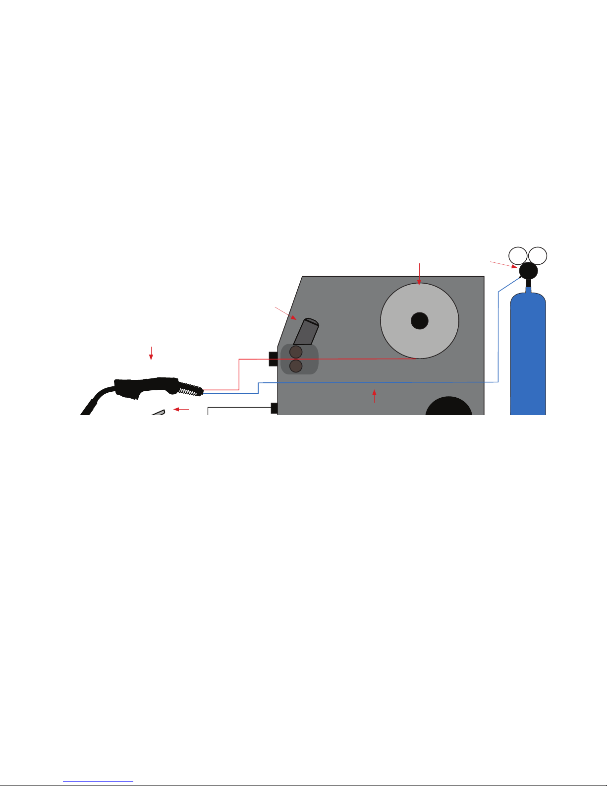
BASIC MIG WELDING GUIDE - MIG (METAL INERT GAS) WELDING
Denition of MIG Welding - MIG (metal inert gas) welding also known as GMAW (gas metal arc
welding) or MAG (metal active gas welding), is a semi-automatic or automatic arc welding process
in which a continuous and consumable wire electrode and a shielding gas are fed through a welding gun. A constant voltage, direct current power source is most commonly used with MIG welding.
There are four primary methods of metal transfer in MIG welding, called short circuit (also known as
dip transfer) globular transfer, spray transfer and pulsed-spray, each of which has distinct properties
and corresponding advantages and limitations. To perform MIG welding, the basic necessary equipment is a welding gun, a wire feed unit, a welding power supply, an electrode wire, and a shielding
gas supply. Short circuit transfer is the most common used method whereby the wire electrode is
fed continuously down the welding torch through to and exiting the contact tip. The wire touches the
work piece and causes a short circuit the wire heats up and begins to form a molten bead, the bead
MIG Circuit Diagram
1
2
3
4
5 6
1. Mig Torch
2. Work Piece
3. Power Source
4. Wire Feeder
5. Wire Spool
6. Gas
Page 25
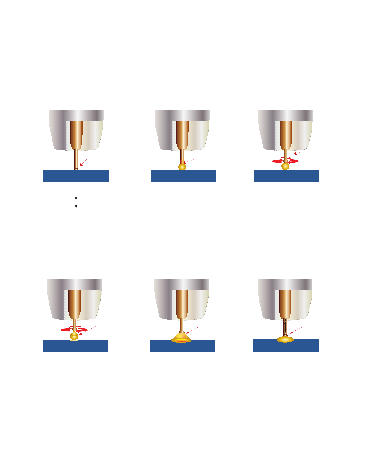
25
The wire approaches the work
piece and touches the work creating a short circuit between the
wire and the base metal, because
there is no space between the wire
and the base metal there is no arc
and current ows through the wire.
The wire cannot support all the
current ow, resistance builds
up and the wire becomes hot
and weak and begins to melt
The current ow creates a magnetic eld that begins to pinch the
melting wire forming it into droplet
short circuit wire heating
magnetic
eld pinches
wire
The pinch causes the forming
droplet to separate and fall towards the now creating weld pool.
An arc is created at the separation
of the droplet and the heat and force
of the arc attens out the droplet
into the weld pool. The heat of the
arc melts the end of the wire slightly
as it feeds towards the base metal
The wire feed speed overcomes
the heat of the arc and the wire
again approaches the work to
short circuit and repeat the cycle.
droplet
separates
arc attens
the droplet
cycle
repeats
BASIC MIG WELDING GUIDE - MIG (METAL INERT GAS) WELDING
Short Circuit Transfer - Short circuit transfer is the most common used method whereby the wire
electrode is fed continuously down the welding torch through to and exiting the contact tip. The
wire touches the work piece and causes a short circuit the wire heats up and begins to form a
molten bead, the bead separates from the end of the wire and forms a droplet that is transferred
into the weld pool. This process is repeated about 100 times per second, making the arc appear
constant to the human eye.
Page 26
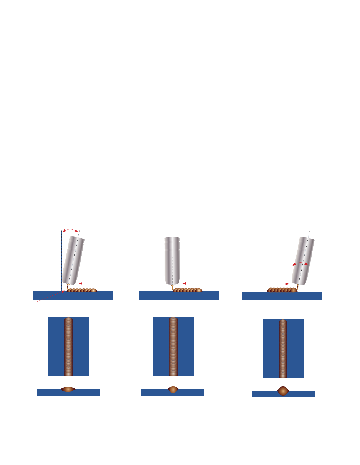
26
10°
wire pointed ahead of bead wire pointed back into bead
travel direction travel direction travel direction
(A) Push Technique (B) Gun Perpendicular (C) Drag Technique
10°
at even weld prole
light penetration
narrower weld prole
even penetration
narrow higher weld prole
more penetration
BASIC MIG WELDING GUIDE
Good weld quality and weld prole depends on gun angle, direction of travel, electrode extension
(stick out), travel speed, thickness of base metal, wire feed speed (amperage) and arc voltage.
To follow are some basic guides to assist with your setup.
Gun Position - Travel Direction, Work Angle
Gun position or technique usually refers to how the wire is directed at the base metal, the angle
and travel direction chosen. Travel speed and work angle will determine the characteristic of the
weld bead prole and degree of weld penetration.
Push Technique - The wire is located at the leading edge of the weld pool and pushed towards
the un-melted work surface. This technique offers a better view of the weld joint and direction of
the wire into the weld joint. Push technique directs the heat away from the weld puddle allowing
faster travel speeds providing a atter weld prole with light penetration - useful for welding thin
materials. The welds are wider and atter allowing for minimal clean up / grinding time.
Perpendicular Technique - The wire is fed directly into the weld, this technique is used prima-
rly for automated situations or when conditions make it necessary. The weld prole is generally
higher and a deeper penetration is achieved.
Drag Technique - The gun and wire is dragged away from the weld bead. The arc and heat is
concentrated on the weld pool, the base metal receives more heat, deeper melting, more penetra-
tion and the weld prole is higher with more build up.
Page 27
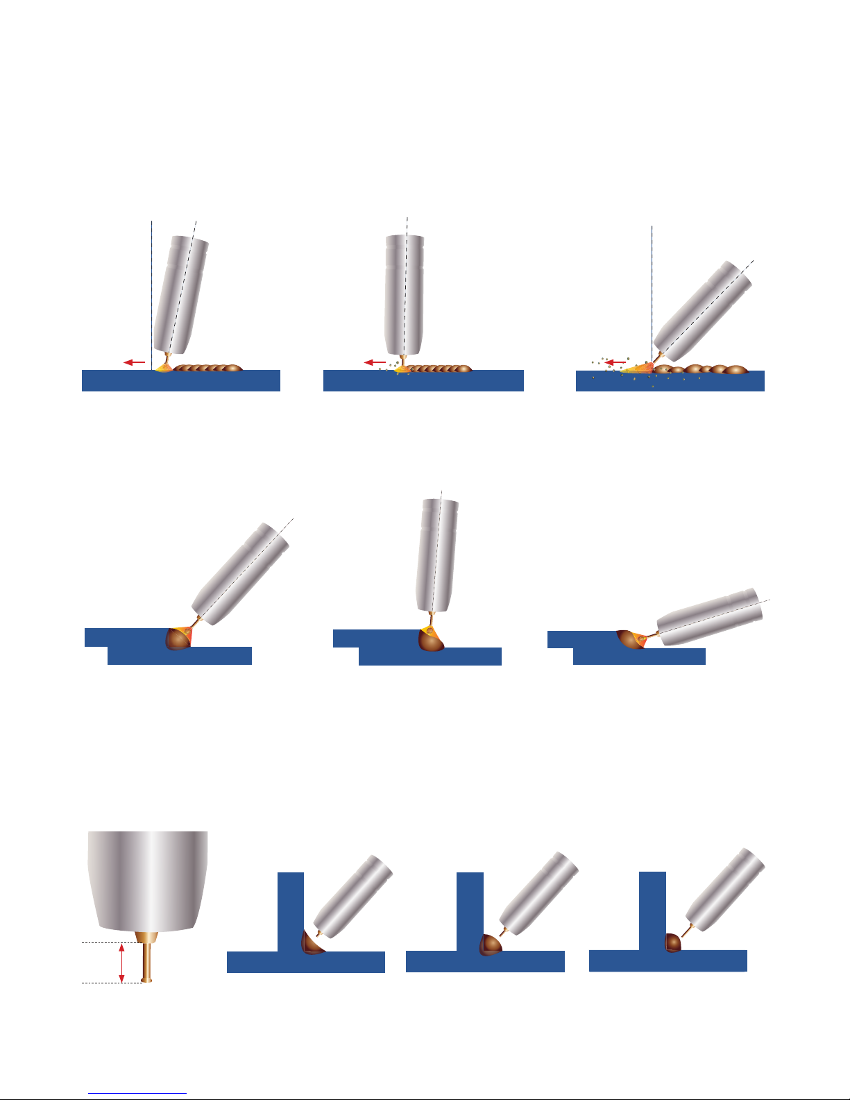
27
BASIC MIG WELDING GUIDE
Travel Angle - Travel angle is the right to left angle relative to the direction of welding. A travel
angle of 5°- 15° is ideal and produces a good level of control over the weld pool. A travel angle
greater that 20° will give an unstable arc condition with poor weld metal transfer, less penetration,
high levels of spatter, poor gas shield and poor quality finished weld.
Angle 5°- 15°
Not enough angle Angle more than 20°
good level of control over the
weld pool, even at weld
less control over the weld pool
more spatter
poor control, unstable arc, less
penetration, lots of spatter
Angle to Work - The work angle is the forward back angle of the gun relative to the work piece.
The correct work angle provides good bead shape, prevents undercut, uneven penetration, poor
gas shield and poor quality finished weld.
Correct angle
Not enough angle
Too much angle
good level of control over the
weld pool, even at weld
less control over the weld pool
more spatter
poor control, unstable arc, less
penetration, lots of spatter
Stick Out- Stick out is the length of the unmelted wire protruding from the end of the contact tip.
A constant even stick out of 1/8-1/4” will produce a stable arc, and an even current ow providing
good penetration and even fusion. Too short stick out will cause an unstable weld pool, produce
spatter and over heat the contact tip. Too long stick out will cause an unstable arc, lack of penetration, lack of fusion and increase spatter.
Normal stick out
Too short
Too long
Even arc, good penetration
even fusion, good nish
Unstable arc, spatter, over
heat contact tip
Unstable arc, spatter, poor
penetration and fusion
‘1/8-1/4”
Page 28
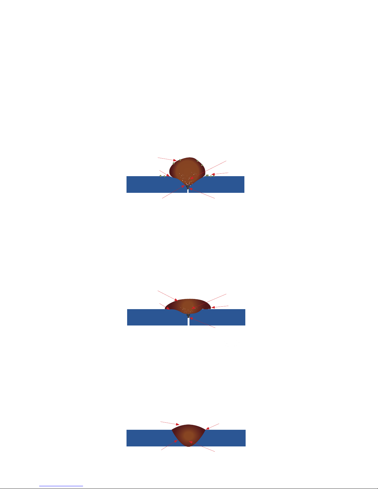
28
Travel Speed - Travel speed is the rate that the gun is moved along the weld joint and is usually
measured in mm per minute. Travel speeds can vary depending on conditions and the welders
skill and is limited to the welders ability to control the weld pool. Push technique allows faster
travel speeds than Drag technique. Gas ow must also correspond with the travel speed, increasing with faster travel speed and decreasing with slower speed. Travel speed needs to match the
amperage and will decrease as the material thickness and amperage increase.
Too Slow Travel Speed - A too slow travel speed produces a large weld with lack of penetration
and fusion. The energy from the arc dwells on top of the weld pool rather than penetrating the
base metal. This produces a wider weld bead with more deposited weld metal per mm than is
required resulting in a weld deposit of poor quality.
cold lap
lack of fusion
lack of joint penetration
porosity
large wide bead
Too Slow Travel Speed
Correct Travel Speed - The correct travel speed keeps the arc at the leading edge of the weld
pool allowing the base metal to melt sufciently to create good penetration, fusion and wetting out
of the weld pool producing a weld deposit of good quality.
good toe fusion
good penetration
good side wall fusion
even shaped bead
Correct Travel Speed
spatter
undercut
lack of joint penetration
lack of fusion
porosity
high narrow bead
Too Fast Travel Speed
Too Fast Travel Speed - A too fast travel speed produces too little heat per inch of travel resulting
in less penetration and reduced weld fusion, the weld bead solidies very quickly trapping gases
inside the weld metal causing porosity. Undercutting of the base metal can also occur and an un-
lled groove in the base metal is created when the travel speed is too fast to allow molten metal to
ow into the weld crater created by the arc heat.
Page 29
29
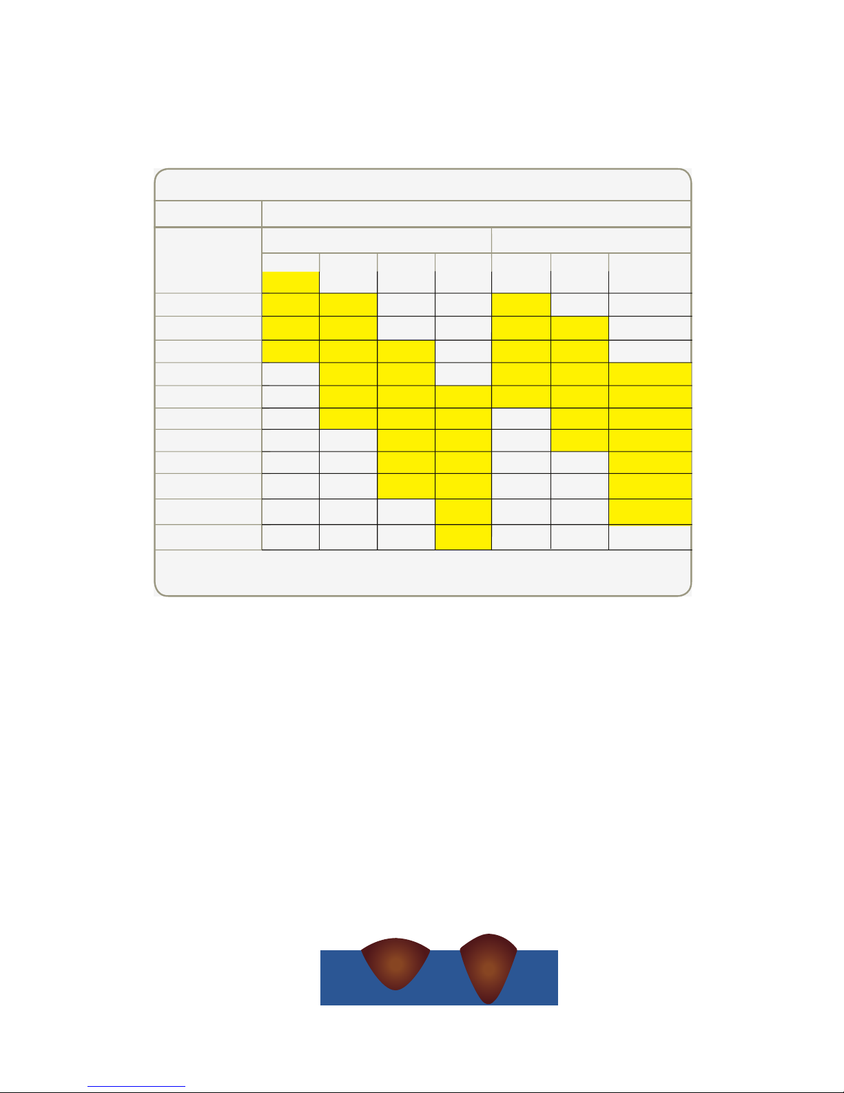
Wire types and sizes - Use the correct wire type for the base metal being welded. Use stainless
steel wire for stainless steel, aluminium wires for aluminium and steel wires for steel.
Use a smaller diameter wire for thin base metals. For thicker materials use a larger wire diameter
and larger machine, check the recommended welding capability of you machine.
As a guide refer to the “Welding Wire Thickness Chart” below.
Gas selection - The purpose of the gas in the MIG process is to protect / shield the wire, the arc
and the molten weld metal from the atmosphere. Most metals when heated to a molten state will
react with the air in the atmosphere, without the protection of the shielding gas the weld produced
would contain defects like porosity, lack of fusion and slag inclusions. Additionally some of the gas
becomes ionised (electrically charged) and helps the current ow smoothly.
The correct gas ow is also very important in protecting the welding zone from the atmosphere.
Too low ow will give inadequate coverage and result in weld defects and unstable arc conditions.
Too high ow can cause air to be drawn into the gas column and contaminate the weld zone.
Use the correct shielding gas. Co2 is good for steel and offers good penetration characteristics,
the weld prole is narrower and slightly more raised than the weld prole obtained from Argon Co2
mixed gas. Argon Co2 mix gas offers better weld ability for thin metals and has a wider range of
setting tolerance on the machine. Argon 75% Co2 25% is a good all round mix suitable for most
applications.
Argon Co2 Co2
Penetration Pattern for Steel
WELDING WIRE DIAMETER CHART
RECOMMENDED WIRE DIAMETERS
MATERIAL
THICKNESS
24 Gauge (.60mm)
22 Gauge (.75mm)
20 Gauge (.90mm)
18 Gauge (1.0mm)
16 Gauge (1.2mm)
14 Gauge (1.9mm)
0.118” / 3.0mm
0.196” / 5.0mm
0.236” / 6.0mm
0.314” / 8.0mm
0.393” / 10.mm
0.472” / 12.0mm
0.025”
0.030”
0.035” 0.040”
MIG SOLID WIRE GASLESS FLUX CORED WIRE
0.030” 0.035”
0.045”
For material thickness of 0.196” / 5.0mm and greater, multi-pass runs or a beveled
joint design may be required depending on the amperage capability of your machine.
Page 30
30
WARNING:
Disconnect the Electrode Holder cable from the machine before using MIG function. If cable is not disconnected welding
voltage is present and can cause arcing or ash.
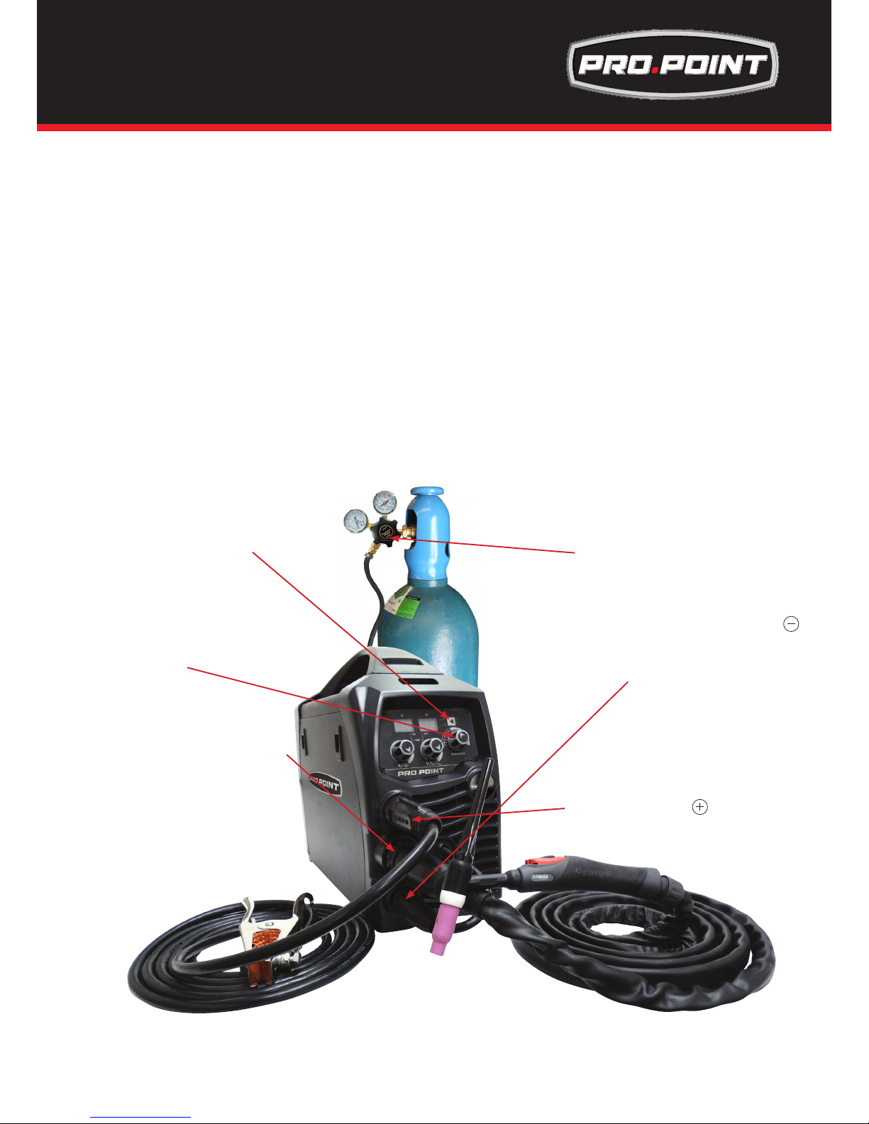
(1) Connect TIG torch to Euro connection socket,
IMPORTANT : When connecting the torch be sure to tighten the connection.
(2) Connect earth lead to Positive
(3) Connect weld power lead to Negative
(4) Turn the power source on and select the TIG function with the MIG/TIG/MMA selector switch.
(5) Set torch operation 2T / 4T.
• When 2T operation is selected press trigger Gas starts, touch and lift arc start,
release trigger Gas and Arc stops.
• When 2T operation is selected with downslope time of either 1 to 10 seconds press trigger Gas starts,
touch and lift arc star, release trigger, after 1 to 10 seconds depending on the downslope time selected
Gas and Arc stops. Crater ll operation is automatic to factory preset level.
• When 4T operation is selected press and release trigger Gas starts, touch and lift arc start,
press and release trigger Gas and Arc stops.
• When 4T operation is selected with downslope time of either 1 to 10 seconds press and release
trigger Gas starts, touch and lift arc start Press and hold trigger, after 1 to 10 seconds depending on
the downslope time selected Arc crater ll downslopes, crater ll operation is automatic to factory
preset level., release trigger Gas and Arc stops
NOTE: This feature is recommend for welding above 70Amps only.
(6) Connect the gas line to regulator and connect the regulator to the gas cylinder.
(6) Connect the gas line to the regulator
and connect to the gas cylinder
(5) Set Torch operation 2T/4T
(1) Connect TIG torch to Euro Connection
(4) Set TIG/MMA/MIG/Spool Gun
selector switch to TIG
IMPORTANT : When connecting the torch
be sure to tighten the connection.
(3) Connect weld power lead to
WARNING:
Ensure that an approved welding helmet, protective clothing and gloves are use for all welding operations
(2) Connect earth lead to
Installation and Set Up for DC TIG Welding for
Pro.Point 145 & 180
TIG Torch Sold Seperatley
Page 31
31
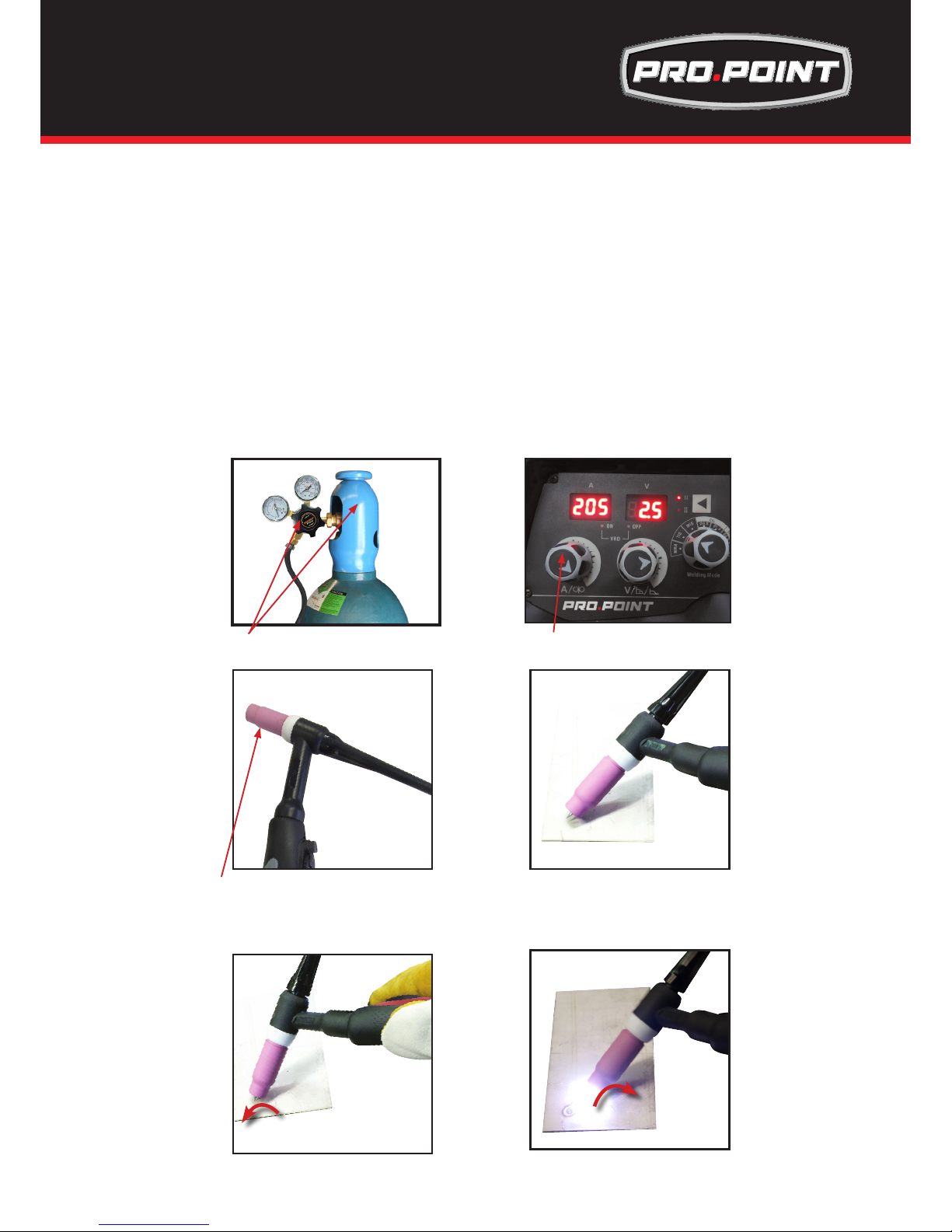
Lift Arc ignition allows the arc to be started easily in DC TIG by simply touching the tungsten to the
work piece and lifting it up to start the arc. This prevents the tungsten tip sticking to the work piece and
breaking the tip from the tungsten electrode. There is a particular technique called “rocking the cup” used in
the Lift Arc process that provides easy use of the Lift Arc function.
(7) Carefully open the valve of the gas cylinder, set the ow to 21-30cfh
(8) Set the welding current using the amperage control dial
(9) Make sure the front end parts of the tig torch are correctly assembled, use the correct size and type of
tungsten electrode for the job, the tungsten electrode requires a sharpened point for DC welding.
(10) Lay the outside edge of the Gas Cup on the work piece with the Tungsten Electrode 1/16 inm from the
work piece. Press the trigger button on TIG torch to start the gas ow.
(11) With a small movement rotate the Gas Cup forward so that the Tungsten Electrode touches the work
piece.
(12) Now rotate the Gas Cup in the reverse direction to lift the Tungsten electrode from the work piece to
create the arc.
(10) Lay the outside edge of the Gas Cup on
the work piece with the Tungsten Electrode
1/16infrom the work piece. Press the trigger
button on TIG torch to start the gas ow.
(11) With a small movement rotate the Gas Cup
forward so that the Tungsten Electrode touches
the work piece.
(12) Now rotate the Gas Cup in the reverse
direction to lift the Tungsten electrode from the
work piece to create the arc.
(9) Assemble front end parts of the TIG torch,
tting a sharpened tungsten suitable for DC
welding.
(8) Set the welding current using
the amperage control dial
(7) Carefully open the valve of the gas
cylinder, set the ow to 6-10 l/min
tt
LIFT ARC DC TIP Operatiom for Pro.Point for
145 & 180
Page 32
32
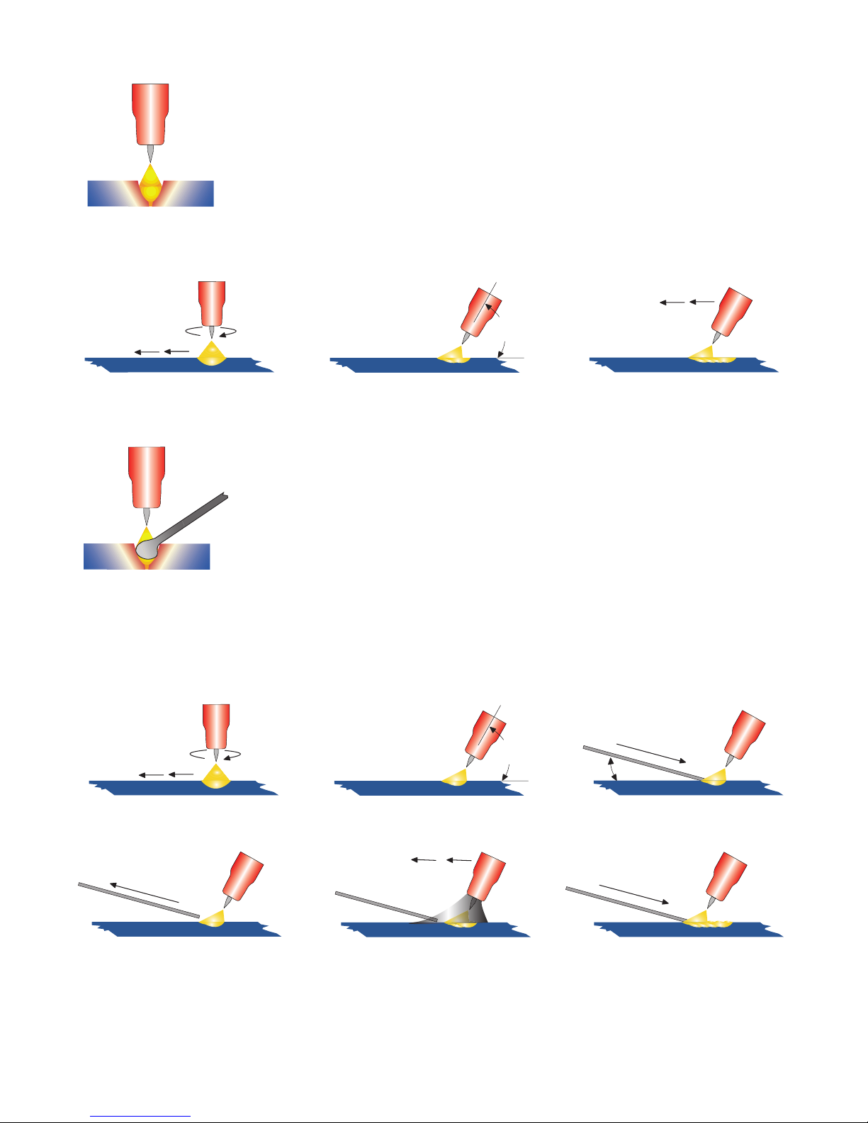
TIG Welding with Filler Wire Technique
It is necessary in many situations with TIG welding to add a ller wire into the weld
pool to build up weld reinforcement and create a strong weld. Once the arc is started
the torch tungsten is held in place until a weld pool is created, a circular movement of
the tungsten will assist is creating a weld pool of the desired size. Once the weld pool
is established tilt the torch at about a 75° angle and move smoothly and evenly
along the joint. The ller metal is introduced to the leading edge of the weld
pool. The ller wire is usually held at about a 15° angle and fed into the lead-
ing edge of the molten pool, the arc will melt the ller wire into the weld pool as the torch is moved
forward. Also a dabbing technique can be used to control the amount of ller wire added, the wire
is fed into the molten pool and retracted in a repeating sequence as the torch is moved slowly and
evenly forward. It is important during the welding to keep the molten end of the ller wire inside the
gas shield as this protects the end of the wire from being oxidized and contaminating the weld pool.
75°
15°
Form a weld pool
Travel direction
Angle torch Add Tig ller wire
Retract the ller wire Move the torch forward to
the front of the weld pool
Repeat the process
gas
shield
TIG WELDING FUSION TECHNIQUES
Manual TIG welding is often considered the most difcult of all the welding processes.
Because the welder must maintain a short arc length, great care and skill are required
to prevent contact between the electrode and the workpiece. Similar to Oxygen
Acetylene torch welding, Tig welding normally requires two hands and in most instances
requires the welder to manually feed a ller wire into the weld pool with one hand
while manipulating the welding torch in the other. However, some welds combining thin
materials can be accomplished without ller metal like edge, corner, and butt joints.
This is known as Fusion welding where the edges of the metal pieces are melted together using only the
heat and arc force generated by the TIG arc. Once the arc is started the torch tungsten is held in place until
a weld pool is created, a circular movement of the tungsten will assist is creating a weld pool of the desired
size. Once the weld pool is established tilt the torch at about a 75° angle and move smoothly and evenly
along the joint while fusing the materials together.
75°
Form a weld pool Angle torch Move the torch slowly
and evenly forward
Travel direction
Page 33

33
Tungsten Electrodes
Tungsten is a rare metallic element used for manufacturing TIG welding electrodes. The TIG process relies on tung-
sten’s hardness and high-temperature resistance to carry the welding current to the arc. Tungsten has the highest
melting point of any metal, 3,410 degrees Celsius.
Tungsten electrodes are nonconsumable and come in a variety of sizes, they are made from pure tungsten or an alloy of tungsten and other rare earth elements. Choosing the correct tungsten depends on the material being welded,
the amount of amps required and whether you are using AC or DC welding current.
Tungsten electrodes are colour-coded at the end for easy identication.
Below are the most commonly used tungsten electrodes found in the New Zealand and Australian market.
Thoriated
Thoriated tungsten electrodes (AWS classication EWTh-2) contain a minimum of 97.30 percent tungsten and 1.70
to 2.20 percent thorium and are called 2 percent thoriated. They are the most commonly used electrodes today and
are preferred for their longevity and ease of use. Thorium increases the electron emission qualities of the electrode,
which improves arc starts and allows for a higher current-carrying capacity. This electrode operates far below its melting temperature, which results in a considerably lower rate of consumption and eliminates arc wandering for greater
stability. Compared with other electrodes, thoriated electrodes deposit less tungsten into the weld puddle, so they
cause less weld contamination.
Thorium however is a low-level radioactive hazard and many users have switched to other alternatives. Regarding the radioactivity, thorium is an alpha emitter but when it is enclosed in a tungsten matrix the risks are negligible.
Thus holding a stick of Thoriated tungsten in your hand should not pose a great threat unless a welder has open cuts
on their skin. Thoriated tungsten should not get in contact with open cuts or wounds. The more signicant danger
to welders can occur when thorium oxide gets into the lungs. This can happen from the exposure to vapours during
welding or from ingestion of material/dust in the grinding of the tungsten. Follow the manufacturer’s warnings, instructions, and the Material Safety Data Sheet (MSDS) for its use.
Ceriated (Color Code: Orange)
Ceriated tungsten electrodes (AWS classication EWCe-2) contain a minimum of 97.30 percent tungsten and 1.80 to
2.20 percent cerium and are referred to as 2 percent ceriated. Ceriated tungstens perform best in DC welding at low
current settings. They have excellent arc starts at low amperages and become popular in such applications as orbital
tube welding, thin sheet metal work. They are best used to weld carbon steel, stainless steel, nickel alloys, and
titanium, and in some cases it can replace 2 percent thoriated electrodes. Ceriated tungsten is best suited for lower
amperages it should last longer than Thoriated tungsten higher amperage applications are best left to Thoriated or
Lanthanated tungsten.
Lanthanated (Color Code: Gold)
Lanthanated tungsten electrodes (AWS classication EWLa-1.5) contain a minimum of 97.80 percent tungsten and
1.30 percent to 1.70 percent lanthanum, and are known as 1.5 percent lanthanated. These electrodes have excellent
arc starting, a low burn off rate, good arc stability, and excellent re-ignition characteristics. Lanthanated tungstens
also share the conductivity characteristics of 2 percent thoriated tungsten. Lanthanated tungsten electrodes are ideal
if you want to optimise your welding capabilities. They work well on AC or DC electrode negative with a pointed end,
or they can be balled for use with AC sine wave power sources. Lanthanated tungsten maintains a sharpened point
well, which is an advantage for welding steel and stainless steel on DC or AC from square wave power sources.
Zirconiated (Color Code: White)
Zirconiated tungsten electrodes (AWS classication EWZr-1) contain a minimum of 99.10 percent tungsten and 0.15
to 0.40 percent zirconium. Most commonly used for AC welding Zirconiated tungsten produces a very stable arc and
is resistant to tungsten spitting. It is ideal for AC welding because it retains a balled tip and has a high resistance to
contamination. Its current-carrying capacity is equal to or greater than that of thoriated tungsten. Zirconiated tungsten
is not recommended for DC welding.
Tungsten Electrodes Rating for Welding Currents
Tungsten DC Current Amps AC Current Amps AC Current Amps
Diameter Torch Negative Un-Balanced Wave Balanced Wave
mm 2% Thoriated 0.8% Zirconiated 0.8% Zirconiated
3/64” (0.040”) 15 - 80 15 - 80 20 - 60
1/16” (.062” & .060”) 70 -150 70 - 150 60 - 120
3/32” (.93”) 150- 250 140 - 235 100 - 180
1/8” (.125”) 250 - 400 225 - 325 160 - 250
5/32” (.156”) 400 - 500 300 - 400 200 - 320
Page 34
34
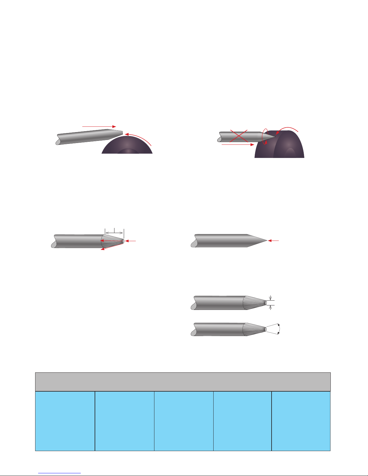
Electrode Included Angle/Taper - DC Welding
Tungsten electrodes for DC welding should be ground longitudinally and concentrically with diamond wheels to a
specic included angle in conjunction with the tip/at preparation. Different angles produce different arc shapes and
offer different weld penetration capabilities. In general, blunter electrodes that have a larger included angle provide
the following benets:
• Last Longer
• Have better weld penetration
• Have a narrower arc shape
• Can handle more amperage without eroding.
Sharper electrodes with smaller included angle provide:
• Offer less arc weld
• Have a wider arc
• Have a more consistent arc
The included angle determines weld bead shape and size. Generally, as the included angle increases, penetration
increases and bead width decreases.
Tungsten Preparation
Always use DIAMOND wheels when grinding and cutting. While tungsten is a very hard material, the surface of a
diamond wheel is harder, and this makes for smooth grinding. Grinding without diamond wheels, such as aluminium
oxide wheels, can lead to jagged edges, imperfections, or poor surface nishes not visible to the eye that will contribute to weld inconsistency and weld defects.
Always ensure to grind the tungsten in a longitudinal direction on the grinding wheel. Tungsten electrodes are manufactured with the molecular structure of the grain running lengthwise and thus grinding crosswise is “grinding against
the grain.” If electrodes are ground crosswise, the electrons have to jump across the grinding marks and the arc can
start before the tip and wander. Grinding longitudinally with the grain, the electrons ow steadily and easily to the end
of the tungsten tip. The arc starts straight and remains narrow, concentrated, and stable.
grind longitudinal on the
grinding wheel
don’t grind across
the grinding wheel
at tip
2.5 times tungsten diameter
pointed tip
Electrode Tip/Flat
The shape of the tungsten electrode tip is an important process variable in precision arc welding. A good selection
of tip/at size will balance the need for several advantages. The bigger the at, the more likely arc wander will occur
and the more difcult it will be to arc start. However, increasing the at to the maximum level that still allows arc start
and eliminates arc wonder will improve the weld penetration and increase the electrode life. Some welders still grind
electrodes to a sharp point, which makes arc starting easier. However, they risk decreased welding performance from
melting at the tip and the possibility of the point falling off into the weld pool.
at spot diameter
included angle
Tungsten Diameter at Constant Included Current Range Current Range
Diameter the Tip - mm Angle - Degrees Amps Pulsed Amps
3/64” (0.040”) .250 20 05 - 30 05 - 60
1/16” (.062” & .060”) .500 25 08 - 50 05 - 100
1/16” (.062” & .060”) .800 30 10 - 70 10 - 140
3/32” (.93”) .800 35 12 - 90 12 - 180
3/32” (.93”) 1.100 45 15 - 150 15 - 250
1/8” (.125”) 1.100 60 20 - 200 20 - 300
1/8” (.125”) 1.500 90 25 - 250 25 - 350
These parts are manufactured in China and are oered as
replacement parts suitable for “TWECO” style torches.
Rating: 200A CO2 150A mixed gas, EN60974-7 @ 60% duty cycle. 0.6 to 1.2mm / 0.025” to 0.045
47/34” wires
TWC2 STYLE MIG TORCH
Description
1 Adjustable Nozzle Insulator
2 TW No.2 Metal Jacket Neck Assembly
45 Degreet Neck Assembly
60 Degreet Neck Assembly
3 Block C/W Spacer & Screws
4 Control Wire Terminals
5 Hose Clamp 18.5mm / (47/64)
6 Spring Cable Support Small & Ball Joint
7 Hyperex C/Assy X 10ft Euro
Hyperex C/Assy X 12ft Euro
Hyperex C/Assy X 15ft Euro
Hyperex C/Assy X 10ft
Hyperex C/Assy X 12ft
Hyperex C/Assy X 15ft
8 Handle With Hook & Screw
Description
9 Grey Trigger Switch
10 Hanger Hook
11 Screw Kit
112 Cable Terminal Male
13 Cable End Lock Nut (M12 X 1.0)
14 Cable Support
15 Gun Plug Housing C/W Nut
16 Gun Plug Screw
17 Gun Plug Nut
18 Gun Plug Terminal Female
19 TWC Euro Gun Plug Body
20 Gun Plug ‘O’ Ring
21 Liner Retaining Nut
*
Wear parts next page
*
Wear parts next page
1
2
356
14
12
13
18
15 16 17
19
20
21
8
7
9
10
11
4
TWC2 Air Cooled Mig Welding Torch
Rating: 200A CO2 150A mixed gas, EN60974-7 @ 60% duty cycle. 0.6 to 1.2mm / 0.023” to 0.047” wires
TWC2 STYLE MIG TORCH
Page 35
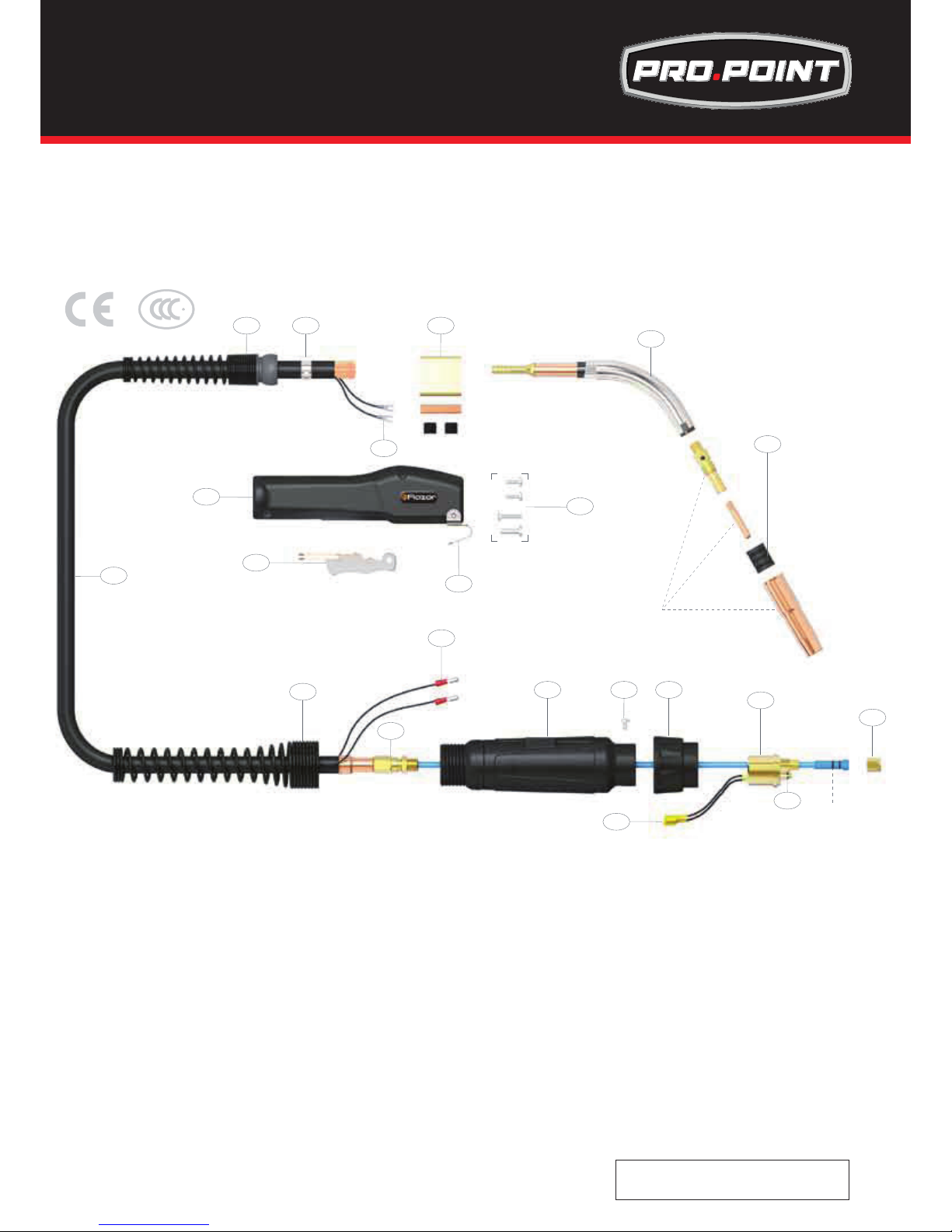
35
These parts are manufactured in China and are oered as
replacement parts suitable for “TWECO” style torches.
Rating: 200A CO2 150A mixed gas, EN60974-7 @ 60% duty cycle. 0.6 to 1.2mm / 0.025” to 0.045
47/34” wires
TWC2 STYLE MIG TORCH
Description
1 Adjustable Nozzle Insulator
2 TW No.2 Metal Jacket Neck Assembly
45 Degreet Neck Assembly
60 Degreet Neck Assembly
3 Block C/W Spacer & Screws
4 Control Wire Terminals
5 Hose Clamp 18.5mm / (47/64)
6 Spring Cable Support Small & Ball Joint
7 Hyperex C/Assy X 10ft Euro
Hyperex C/Assy X 12ft Euro
Hyperex C/Assy X 15ft Euro
Hyperex C/Assy X 10ft
Hyperex C/Assy X 12ft
Hyperex C/Assy X 15ft
8 Handle With Hook & Screw
Description
9 Grey Trigger Switch
10 Hanger Hook
11 Screw Kit
112 Cable Terminal Male
13 Cable End Lock Nut (M12 X 1.0)
14 Cable Support
15 Gun Plug Housing C/W Nut
16 Gun Plug Screw
17 Gun Plug Nut
18 Gun Plug Terminal Female
19 TWC Euro Gun Plug Body
20 Gun Plug ‘O’ Ring
21 Liner Retaining Nut
*
Wear parts next page
*
Wear parts next page
1
2
356
14
12
13
18
15 16 17
19
20
21
8
7
9
10
11
4
TWC2 Air Cooled Mig Welding Torch
Rating: 200A CO2 150A mixed gas, EN60974-7 @ 60% duty cycle. 0.6 to 1.2mm / 0.023” to 0.047” wires
TWC2 STYLE MIG TORCH
tt
TWECO®2 MIG Welding Torch
Part Number: 8613002
Sold Seperatley
Page 36
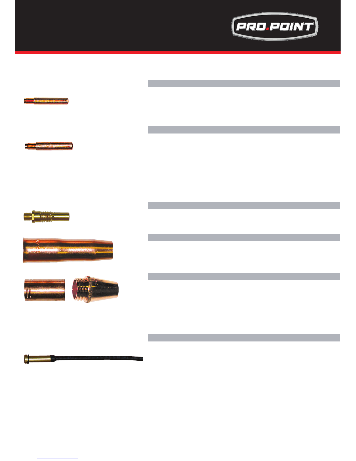
36
TWC2 Contact Tips
QTY10
QTY10
QTY10
/ 0.030”
/ 0.035”
/ 0.040”
Contact tip 0.8mm
Contact tip 0.9mm
Contact tip 1.0mm
Contact tip 1.2mm / 0.045” QTY10
Liners
TWC2 Liners
Liner 15 ft 0.8 - 0.9mm / 0.030” - 0.035”
Liner 15ft 1.0 - 1.2mm / 0.040” - 0.0457”
Liner 15ft 1.0 - 1.2mm / 0.040” - 0.045” Alloy
These parts are manufactured in China and are oered as
replacement parts suitable for “TWECO” style torches.
TWC2 Torch Nozzle
Nozzle Adjustable 13mm / (33/67)
Nozzle Adjustable 16mm / (5/8)
QTY2
QTY2
TWC2 Torch Nozzle Fixed
Nozzle Insulator QTY2
Nozzle xed 13mm / (33/67)
Nozzle xed 16mm / (5/8) QTY2
Nozzle xed 13mm / (33/67)
Nozzle xed 16mm / (5/8) QTY2
QTY2
QTY2
TWC2 Gas Diuser
Gas Diuser
QTY2
Gas Diuser to suit xed nozzle QTY2
TWC2 Contact Tips H/D
Contact H/D tip 0.8mm / 0.030”
Contact H/D tip 0.9mm / 0.035”
Contact H/D tip 1.0mm / 0.040”
Contact H/D tip 1.2mm / 0.045”
Contact H/D tip 1.4mm / 0.052:
Contact H/D tip 2.0mm / (5/64)
Contact H/D Ali tip 1.2mm / 0.045”
Contact H/D Ali tip 1.6mm / (1/16) QTY10
QTY10
QTY10
QTY10
QTY10
QTY10
QTY10
QTY10
MIG Torch 8613002 Spare Part
Front End Consumables
Sold Seperately
Page 37
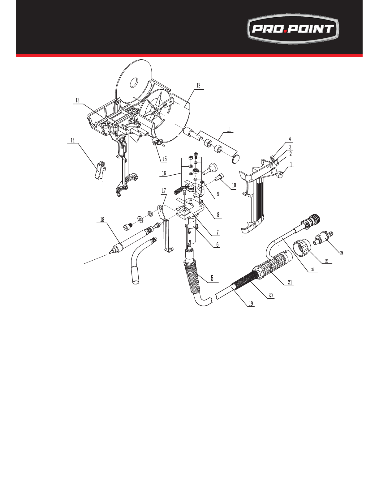
37
tt
Duty Cycle 35% @ 200Amp
Wear Parts Next Page
Description
1 Speed Adjusting Knob
2 Open/Close Button
3 Left-Gun Case
4 Hang Hook
5 Spring Support
6 Motor
7 Motor Plate
8 Suspension Screw
9 Drive Roll Assembly
10 Wire Nipple
11 Spool Shaft
12 Right-Gun Case
13 Upper-Gun Case
14 Switch
Description
15 Potentiometer
16 Push Roll
17 Conducting Board
18 Conducting Tube
19 Welding Cable
20 Spring Support (Back)
21 Adaptor Support
22 Adaptor Support Nut
23 Adaptor
24 4 Pin Plug
200 AMP Spool Gun Parts Breakdown
Part Number: 8612517
Sold Seperately
Page 38
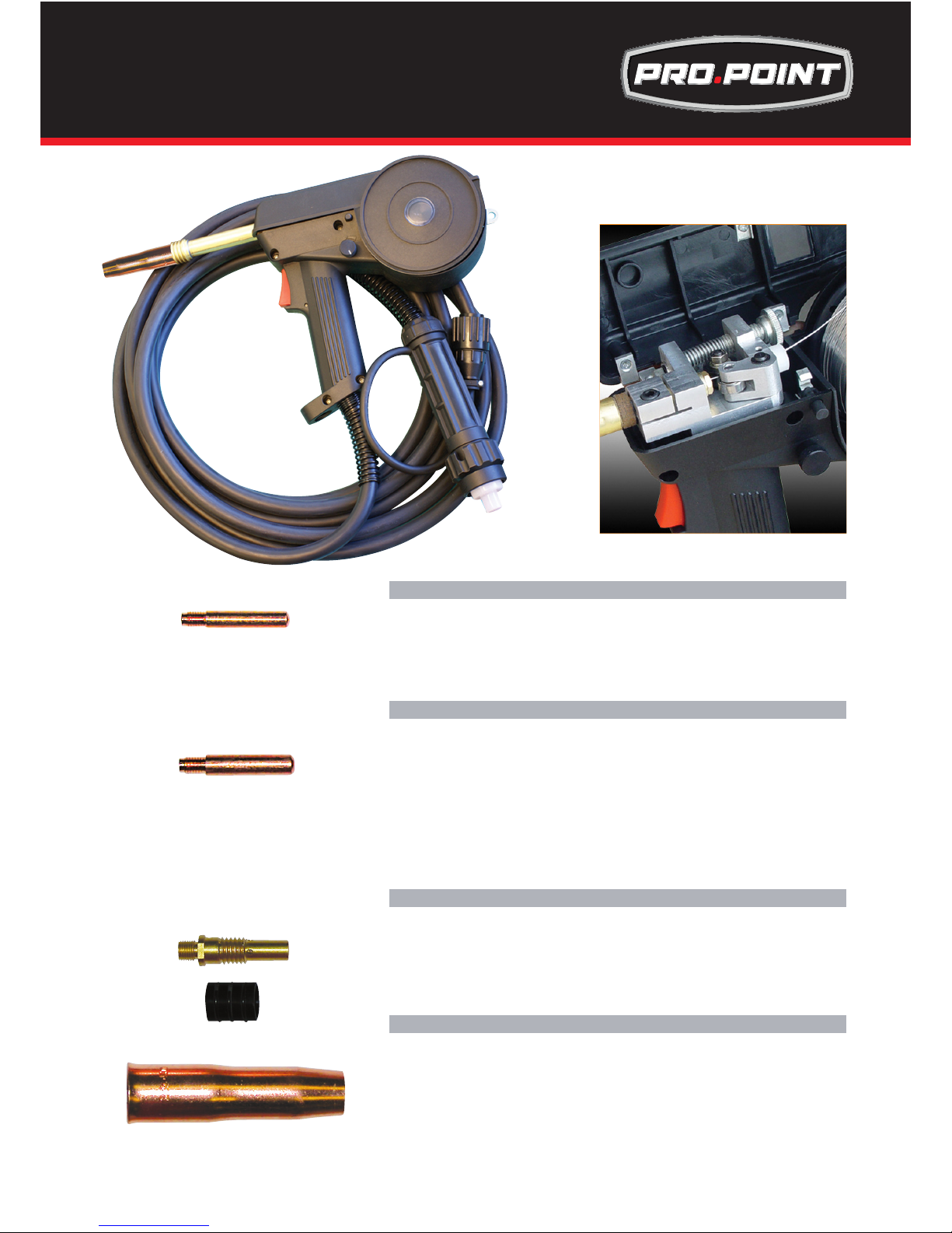
38
TWC2 Contact Tips
Contact tip 0.8mm / 0.030”
Contact tip 0.9mm / 0.035”
Contact tip 1.0mm / 0.040”
Contact tip 1.2mm / 0.045”
TWC2 Contact Tips H/D
Contact H/D tip 0.8mm / 0.030”
Contact H/D tip 0.9mm / 0.035”
Contact H/D tip 1.0mm / 0.040”
Contact H/D tip 1.2mm / 0.045”
Contact H/D tip 1.4mm / 0.052:
Contact H/D tip 2.0mm / (5/64)
Contact H/D Ali tip 1.2mm / 0.045”
Contact H/D Ali tip 1.6mm / (1/16)
TWC2 Gas Diffuser & Insulator
Gas Diffuser
Gas Diffuser suit fixed nozzle
Insulator
TWC2 TORCH Nozzle
Nozzle Adjustable 13mm / (33/67)
Nozzle Adjustable 16mm / (5/8)
These parts are not original and are offered as replacement parts suitable for “TWECO” style torches.
200 AMP Spool Gun Parts Breakdown
Part Number: 8612517
Sold Seperately
Page 39
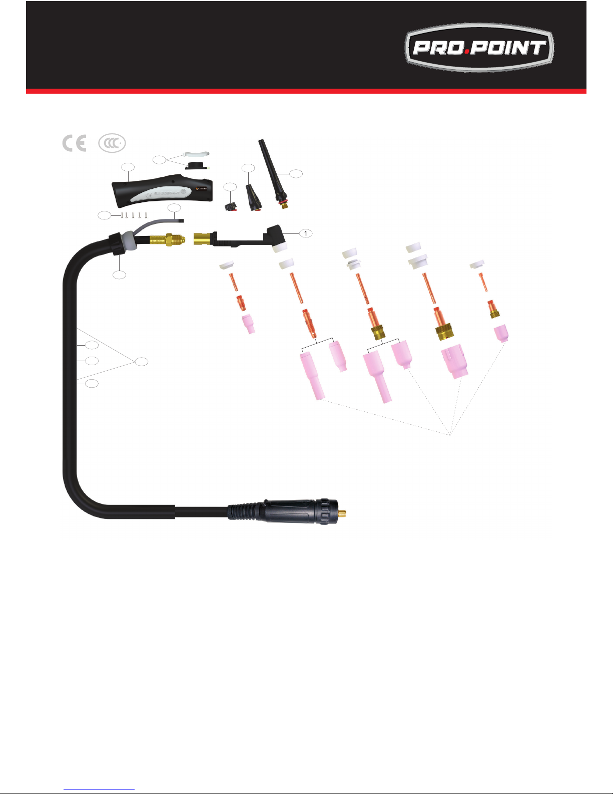
39
©All rights reserved. No part of this publication may be reproduced, stored in a retrieval system or transmitted by any means,
electronic, mechanical, photocopying or otherwise without the prior permission of ©Uniarc® the copyright holder.
Wear Parts Identification Next Page
Stubby series
Standard series
Gas Lens series
Large Gas Lens series
Stubby Gas Lens series
*
2
3
6
5
8
7
9
10
11
12
13
4
180A AIR COOLED TIG WELDING TORCH
Rating:180Amp DC, 125Amp AC @35% duty cycle.
tt
Description
12 Neoprene Cover X 3.2mt
Neoprene Cover X 7.2mt
13 Sheath X 12.5ft Inc Leather Cover
Sheath X 25ft Inc Leather Cover
Description
1 Torch head
Torch head flexible
2 Back cap long
3 Medium back cap
4 Short back cap
5 Momentary Kit
6 Trigger Lead 12.5ft
Trigger Lead 25ft
7 Screw Pack
8 Large Ergo Tig Handle
9 Large Knuckle Joint
10 Leather Cover X 0.8mt
11 Jointing Repair Kit
TIG Torch 8618456 Parts Breakdown
Sold Seperately
Page 40
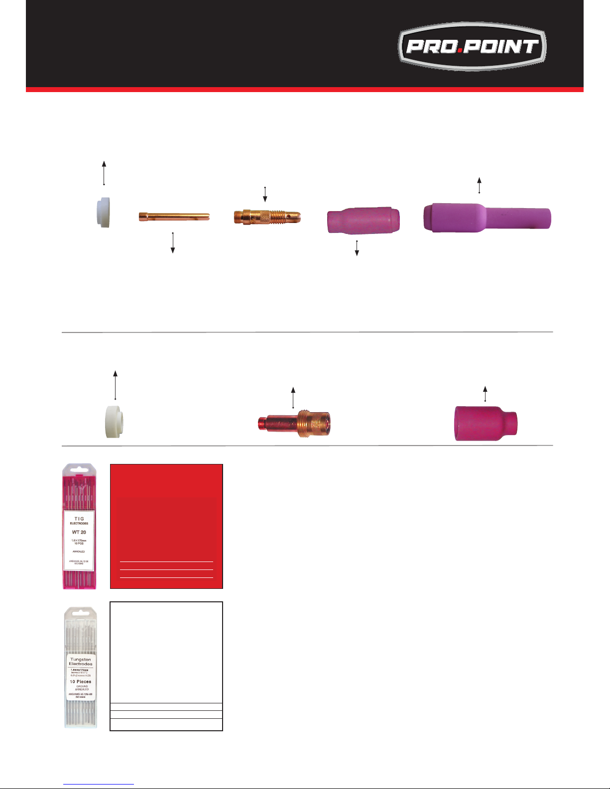
40
©All rights reserved. No part of this publication may be reproduced, stored in a retrieval system or transmitted by any means,
electronic, mechanical, photocopying or otherwise without the prior permission of ©Uniarc® the copyright holder.
Description
Cup Gasket
Description
Collet 1.0mm / 0.040”
Collet 1.6mm / ((1/16)
Collet 2.4mm / (3/32)
Collet 3.2mm / (1/8)
Description
Collet Body 1.0mm / 0.040”
Collet Body 1.6mm / (1/16)
Collet Body 2.4mm / (3/32)
Collet Body 3.2mm / (1/8)
Description
Alumina Nozzle Ø 6mm / (15/64) #4
Alumina Nozzle Ø 8mm / (5/16) #5
Alumina Nozzle Ø 10mm / (25/64) #6
Alumina Nozzle Ø 11mm / (7/16) #7
Alumina Nozzle Ø 13mm / (33/64) #8
Alumina Nozzle Ø 16mm / (5/8) #10
Alumina Nozzle Ø 19mm / (3/4) #12
Description
Long Alumina Nozzle Ø 8mm / (5/16) #5L
Long Alumina Nozzle Ø 10mm / (25/64) #6L
Long Alumina Nozzle Ø 11mm / (7/16) #7L
Description
Gas Lens Gasket
Description
Gas Lens Body 1.6mm / (1/16)
Gas Lens Body 2.4mm / (3/32)
Gas Lens Body 3.2mm /(1/8)
Description
Gas lens ceramic 8.0mm / (5/16)
Gas lens ceramic 7.0mm / (9/32)
Gas lens ceramic 5.0mm / (13/64)
Compact Gas Lens Front End Parts
Description
1.0mm x 175mm / 0.040” x 6
57
/
64
” thoriated tungsten electrode 2%
1.6mm x 175mm / (1/16) x 6
57
/
64
” thoriated tungsten electrode 2%
2.4mm x 175mm / (3/32) x 6
57
/
64
” thoriated tungsten electrode 2%
3.2mm x 175mm / (1/8) x 6
57
/
64
” thoriated tungsten electrode 2%
Description
1.0mm x 175mm / 0.040” x 6
57
/
64
” zirconiated tungsten electrode 1%
1.6mm x 175mm / (1/16) x 6
57
/
64
” zirconiated tungsten electrode 1%
02.4mm x 175mm / (3/32) x 6
57
/
64
” zirconiated tungsten electrode 1%
3.2mm x 175mm / (1/8) x 6
57
/
64
” zirconiated tungsten electrode 1%
TR0004-16
RED
ANSI/AWS A5.12-98
ISO 6848 WT20
2% Thoriated: Best stability
at medium currents, good arc
starts, medium tendency to
spit, medium erosion rate.
Commonly used for steel and
stainless steel applications
1/16 x 7” (1.6mm x 175mm)
3/32 x 7”
(2.4mm x 175mm)
1/8 x 7”
(3.2mm x 175mm)
WHITE
ANSI/AWS A5.12 M-98
ISO 6848 WZ8
.8% Zirconiated: Balls well, handles
higher current with less spitting, bet-
ter arc starts and arc stability than
pure tungsten
Commonly used for
aluminium applications
1/16 x 7” (1.6mm x 175mm)
3/32 x 7”
(2.4mm x 175mm)
1/8 x 7”
(3.2mm x 175mm)
TR0006-16
tt
TIG Torch 8618456 Spare Part
Sold Seperately
Page 41
41
1: No arc
Possible Reason Suggested Remedy
Incomplete welding circuit Check earth lead is connected. Check all cable connections.
Wrong mode selected Check the ARC selector switch is selected
No power supply Check that the machine is switched on and has a power supply
2: Porosity − small cavities or holes resulting from gas pockets in weld metal.
Possible Reason Suggested Remedy
Arc length too long Shorten the arc length
Work piece dirty, contaminated or
moisture
Remove moisture and materials like paint, grease, oil, and dirt, including mill scale from
base metal
Damp electrodes Use only dry electrodes
3: Excessive Spatter
Possible Reason Suggested Remedy
Amperage too high Decrease the amperage or choose a larger electrode
Arc length too long Shorten the arc length
3: Weld sits on top, lack of fusion
Possible Reason Suggested Remedy
Insufcient heat input Increase the amperage or choose a larger electrode
Work piece dirty, contaminated or
moisture
Remove moisture and materials like paint, grease, oil, and dirt, including mill scale from
base metal
Poor welding technique Use the correct welding technique or seek assistance for the correct technique
4: Lack of penetration
Possible Reason Suggested Remedy
Insufcient heat input Increase the amperage or choose a larger electrode
Poor welding technique Use the correct welding technique or seek assistance for the correct technique
Poor joint preparation Check the joint design and t up, make sure the material is not too thick. Seek assis-
tance for the correct joint design and t up
5: Excessive penetration - burn through
Possible Reason Suggested Remedy
Excessive heat input Reduce the amperage or use a smaller electrode
Incorrect travel speed Try increasing the weld travel speed
6: Uneven weld appearance
Possible Reason Suggested Remedy
Unsteady hand, wavering hand Use two hands where possible to steady up, practice your technique
7: Distortion − movement of base metal during welding
Possible Reason Suggested Remedy
Excessive heat input Reduce the amperage or use a smaller electrode
Poor welding technique Use the correct welding technique or seek assistance for the correct technique
Poor joint preparation and or joint
design
Check the joint design and t up, make sure the material is not too thick. Seek assistance for the correct joint design and t up
7: Electrode welds with different or unusual arc characteristic
Possible Reason Suggested Remedy
Incorrect polarity Change the polarity, check the electrode manufacturer for correct polarity
The following chart addresses some of the common problems of MMA welding. In all cases of equipment malfunction,
the manufacturer’s recommendations should be strictly adhered to and followed.
ARC(Stick) WELDING TROUBLE SHOOTING
tt
Trouble Shooting
Page 42
42
1: Excessive Spatter
Possible Reason Suggested Remedy
Wire feed speed set too high Select lower wire feed speed
Voltage too high Select a lower voltage setting
Wrong polarity set select the correct polarity for the wire being used - see machine setup guide
Stick out too long Bring the torch closer to the work
Contaminated base metal Remove materials like paint, grease, oil, and dirt, including mill scale from base metal
Contaminated mig wire Use clean dry rust free wire. Do not lubricate the wire with oil, grease etc
Inadequate gas ow or too much gas
ow
Check the gas is connected, check hoses, gas valve and torch are not restricted. Set
the gas ow between 21-30cfh ow rate. Check hoses and ttings for holes, leaks etc
Protect the welding zone from wind and drafts
2: Porosity - small cavities or holes resulting from gas pockets in weld metal.
Possible Reason Suggested Remedy
Wrong gas Check that the correct gas is being used
Inadequate gas ow or too much gas
ow
Check the gas is connected, check hoses, gas valve and torch are not restricted. Set
the gas ow between 21-30cfh ow rate. Check hoses and ttings for holes, leaks etc.
Protect the welding zone from wind and drafts
Moisture on the base metal Remove all moisture from base metal before welding
Contaminated base metal Remove materials like paint, grease, oil, and dirt, including mill scale from base metal
Contaminated mig wire Use clean dry rust free wire. Do not lubricate the wire with oil, grease etc
Gas nozzle clogged with spatter,
worn or out of shape
Clean or replace the gas nozzle
Missing or damaged gas diffuser Replace the gas diffuser
Mig torch euro connect o-ring missing or damaged
check and replace the o-ring
4: Wire stubbing during welding
Possible Reason Suggested Remedy
Holding the torch too far away Bring the torch closer to the work and maintain stick out of 5-10mm
Welding voltage set too low Increase the voltage
Wire Speed set too high Decrease the wire feed speed
5: Lack of Fusion − failure of weld metal to fuse completely with base metal or a proceeding weld bead.
Possible Reason Suggested Remedy
Contaminated base metal Remove materials like paint, grease, oil, and dirt, including mill scale from base metal
Not enough heat input Select a higher voltage range and /or adjust the wire speed to suit
Improper welding technique Keep the arc at the leading edge of the weld pool.
Gun angle to work should be between 5 & 15°
Direct the arc at the weld joint
Adjust work angle or widen groove to access bottom during welding
Momentarily hold arc on side walls if using weaving technique
5: Excessive Penetration − weld metal melting through base metal
Possible Reason Suggested Remedy
Too much heat Select a lower voltage range and /or adjust the wire speed to suit
Increase travel speed
The following chart addresses some of the common problems of MIG welding. In all cases of equipment malfunction, the manu-
facturer’s recommendations should be strictly adhered to and followed.
MIG WELDING TROUBLE SHOOTING
Trouble Shooting
Page 43
43
1: No wire feed
Possible Reason Suggested Remedy
Wrong mode selected Check that the TIG/ARC/MIG selector switch set to MIG position
Wrong torch selector switch Check that the STANDARD/SPOOLGUN selector switch is set to STANDARD position
for MIG welding and SPOOLGUN when using the Spoolgun
2: Inconsistent / interrupted wire feed
Possible Reason Suggested Remedy
Adjusting wrong dial Be sure to adjust the WIRE FEED and VOLTAGE dials for MIG welding.
The AMPERAGE dial is for STICK and TIG welding mode
Wrong polarity selected Select the correct polarity for the wire being used - see machine setup guide
Incorrect wire speed setting Adjust the wire feed speed
Voltage setting incorrect Adjust the voltage setting
Mig torch lead too long Small diameter wires and soft wires like aluminium don’t feed well through long torch
leads - replace the torch with a lesser length torch
Mig torch lead kinked or too sharp
angle being held
Remove the kink, reduce the angle or bend
Contact tip worn, wrong size, wrong
type
Replace the tip with correct size and type
Liner worn or clogged (the most
common causes of bad feeding)
Try to clear the liner by blowing out with compressed air as a temporary cure,
it is recommended to replace the liner
Wrong size liner Install the correct size liner
Blocked or worn inlet guide tube Clear or replace the inlet guide tube
Wire misaligned in drive roller groove Locate the wire into the groove of the drive roller
Incorrect drive roller size Fit the correct size drive roller eg; .030in wire requires .030in drive roller
Wrong type of drive roller selected Fit the correct type roller (e.g. knurled rollers needed for ux cored wires)
Worn drive rollers Replace the drive rollers
Drive roller pressure too high Can atten the wire electrode causing it to lodge in the contact tip - reduce the drive
roller pressure
Too much tension on wire spool hub Reduce the spool hub brake tension
Wire crossed over on the spool or
tangled
Remove the spool untangle the wire or replace the wire
Contaminated mig wire Use clean dry rust free wire. Do not lubricate the wire with oil, grease etc
The following chart addresses some of the common WIRE FEED problems during MIG welding. In all cases of equipment
malfunction, the manufacturer’s recommendations should be strictly adhered to and followed.
MIG WIRE FEED TROUBLE SHOOTING
6: Lack of Penetration − shallow fusion between weld metal and base metal
Poor in incorrect joint preparation Material too thick. Joint preparation and design needs to allow access to bottom of
groove while maintaining proper welding wire extension and arc characteristics
Keep the arc at the leading edge of the weld pool and maintain the gun angle at
5 & 15° keeping the stick out between 1/8-1/4in
Not enough heat input Select a higher voltage range and /or adjust the wire speed to suit
Reduce travel speed
Contaminated base metal Remove materials like paint, grease, oil, and dirt, including mill scale from base metal.
MIG WELDING TROUBLE SHOOTING - Continued
tt
Trouble Shooting
Page 44
44
1: Tungsten burning away quickly
Possible Reason Suggested Remedy
Incorrect Gas Check that pure Argon is being used
No gas Check the gas cylinder contains gas and is connected and the torch gas valve is open
Inadequate gas ow Check the gas is connected, check hoses, gas valve and torch are not restricted. Set
the gas ow between 21-30cfh ow rate
Back cap not tted correctly Make sure the torch back cap is tted so that the o-ring is inside the torch body
Torch connected to DC + Connect the torch to the DC- output terminal
Incorrect tungsten being used Check and change the tungsten type if necessary
Tungsten being oxidised after weld
is nished
Keep shielding gas owing 10–15 seconds after arc stoppage. 1 second for each 10
amps of weld current.
2: Contaminated tungsten
Possible Reason Suggested Remedy
Touching tungsten into the weld
pool
Keep tungsten from contacting weld puddle. Raise the torch so that the tungsten is off of
the work piece 1/8-1/4in
Touching the ller wire to the tungsten
Keep the ller wire from touching the tungsten during welding, feed the ller wire into the
leading edge of the weld pool in front of the tungsten
Tungsten melting into the weld pool Check that correct type of tungsten is being used. Too much current for the tungsten
size so reduce the amps or change to a larger tungsten
3: Porosity - poor weld appearance and colour
Possible Reason Suggested Remedy
Incorrect Gas Check that pure Argon is being used
Inadequate gas ow / gas leaks Check the gas is connected, check hoses, gas valve and torch are not restricted. Set
the gas ow between 21-30cfh ow rate. Check hoses and ttings for holes, leaks etc.,
Moisture on the base metal Remove all moisture from base metal before welding
Contaminated base metal Remove materials like paint, grease, oil, and dirt, including mill scale from base metal
Contaminated ller wire Remove all grease, oil, or moisture from ller metal.
Incorrect ller wire Check the ller wire and change if necessary
4: Yellowish residue / smoke on the alumina nozzle & discoloured tungsten
Possible Reason Suggested Remedy
Incorrect Gas Use pure Argon gas
Inadequate gas ow Set the gas ow between 21-30cfh ow rate
Alumina gas nozzle too small for size
of tungsten being used
Increase the size of the alumina gas nozzle
5: Unstable Arc during DC welding
Possible Reason Suggested Remedy
Torch connected to DC + Connect the torch to the DC- output terminal
Contaminated base metal Remove materials like paint, grease, oil, and dirt, including mill scale from base metal.
Tungsten is contaminated Remove 10mm of contaminated tungsten and re grind the tungsten
Arc length too long Lower torch so that the tungsten is off of the work piece 2 - 5mm
The following chart addresses some of the common problems of DC TIG welding. In all cases of equipment malfunction, the
manufacturer’s recommendations should be strictly adhered to and followed.
TIG WELDING TROUBLE SHOOTING
Trouble Shooting
Page 45
45
7: Arc wanders during DC welding
Possible Reason Suggested Remedy
Poor gas ow Check and set the gas ow between 21-30cfh ow rate
Incorrect arc length Lower torch so that the tungsten is off of the work piece 1/8-1/4in
Tungsten incorrect or in poor condition
Check that correct type of tungsten is being used. Remove 1/2in from the weld end of
the tungsten and re sharpen the tungsten
Poorly prepared tungsten Grind marks should run lengthwise with tungsten, not circular. Use proper grinding
method and wheel.
Contaminated base metal Remove contaminating materials like paint, grease, oil, and dirt, including mill scale from
base metal.
Contaminated ller wire Remove all grease, oil, or moisture from ller metal.
Incorrect ller wire Check the ller wire and change if necessary
At initial set up and at regular intervals we recommend to check for gas leakage.
Recommended procedure is as follows:
1. Connect the regulator and gas hose assembly and tighten all connectors and clamps.
2. Slowly open the cylinder valve.
3. Set the ow rate on the regulator to approximately 21-30cfh.
4. Close the cylinder valve and pay attention to the needle indicator of the contents pressure
gauge on the regulator, if the needle drops away towards zero there is a gas leak.
Sometimes a gas leak can be slow and to identify it will require leaving the gas pressure in the
regulator and line for an extended time period. In this situation it is recommended to open the
cylinder valve, set the ow rate to 21-30cfh, close the cylinder valve and check after a
minimum of 15 minutes.
5. If there is a gas loss then check all connectors and clamps for leakage by brushing or spraying
with soapy water, bubbles will appear at the leakage point.
6. Tighten clamps or ttings to eliminate gas leakage.
8: Arc difcult to start or will not start DC welding
Possible Reason Suggested Remedy
Incorrect machine set up Check machine set up is correct
No gas, incorrect gas ow Check the gas is connected and cylinder valve open, check hoses, gas valve and torch
are not restricted. Set the gas ow between 10 - 15 l/min ow rate
Tungsten is contaminated Remove 10mm of contaminated tungsten and re grind the tungsten
Incorrect tungsten size and or tungsten being used
Check and change the size and or the tungsten if required
Loose connection Check all connectors and tighten
Earth clamp not connected to work Connect the earth clamp directly to the work piece wherever possible
TIG WELDING TROUBLE SHOOTING - Continued
tt
Trouble Shooting
Page 46
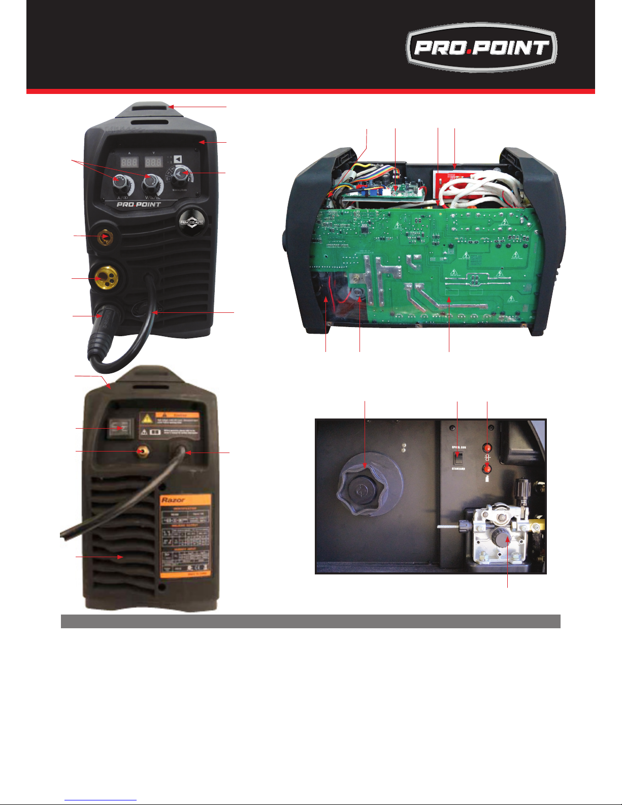
46
1617
14
15
1820
19
10
11
13
12
9
21 22 23
24
# Description
Part Number
1 handle
2 front panel
3 Knob pointer
4 Knob pointer
5 Polarity lead
6 central adaptor
7 quick-connect 35-50
8 9 pin female socket
9 rear panel
10 power switch
11 gas inlet
# Description
12 fan DC24V
13 power cable
14 display pcb
15 plastic packaged solenoid valve
16 silicon bridge plate
17 Control pcb
18 wire feeder motor
19 mainboard
20 Insluation sheet
21 Spool holder
22 Selector switch
23 Wire inch & Gas check button
24 wire feeder motor
1
2
3
8
4
5
6
7
Spare Parts Identification for
Pro.Point 145 & 180
Page 47

47
WARRANTY EXCLUSIONS
This Warranty covers Material and Faulty Workmanship defects only.
This Warranty does not cover damage caused by:
• Normalwearandtearduetousage
• MisuseorabusiveuseofthePRINCESSAUTOinstructionssuppliedwiththeproduct.
• Failuretocleanorimpropercleaningoftheproduct
• Failuretomaintaintheequipmentsuchasregularservicesetc
• Incorrectvoltageornon-authorisedelectricalconnections
• Improperinstallation
• Useofnon-authorised/non-standardparts
• Abnormalproductperformancecausedbyanyancillaryequipmentinterferenceorotherexternalfactors
• Failureoranybreakagecausedbyoverload,droppingorabusivetreatmentorusebythecustomer
• Repair,modicationsorotherworkcarriedoutontheproductotherthanbyanAuthorisedPRINCESSAUTO
Dealers
WARRANTY
As part of Royal Service, a customer may return a defective unit to any Princess Auto location for a new replacement
unit within 3 years of the purchase date.
tt
Warranty/Warranty Exclusions
Page 48

48
NOTES
Page 49

49
NOTES
Page 50

50
PRINCESS AUTO LTD.
Phone: 1-800-665-8685
WWW.PRINCESSAUTO.COM
MADE IN CHINA
 Loading...