

Page 1
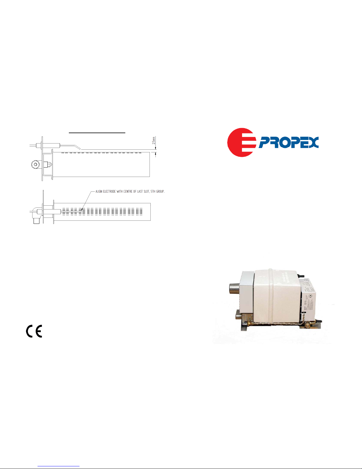
ELECTRODE SETTING
INSTALLATION
&
OPERATION
Malaga 5/5E
INSTRUCTIONS
Storage Water
Heater
All g
as appliances must be installed and/or commissioned
by persons registered with the Gas Safety Register (GB)
or the relevant national organisation.
Manufactured by:
Munster Simms Engineering
Distributed by:
PROPEX HEATSOURCE LTD
Unit 5, Second Avenue Business Park
,
Millbrook, Southampton,
United Kingdom, SO15 0LP
Tel: 023 8052 8555
Fax: 023 8052 8800
Website: www.propexheatsource.co.uk
E.mail: [email protected]
0120
Ref No: 180.119
ISSUE I
Page 2
USER INSTRUCTIONS
Read the User Installation and Operation Instructions carefully before using this
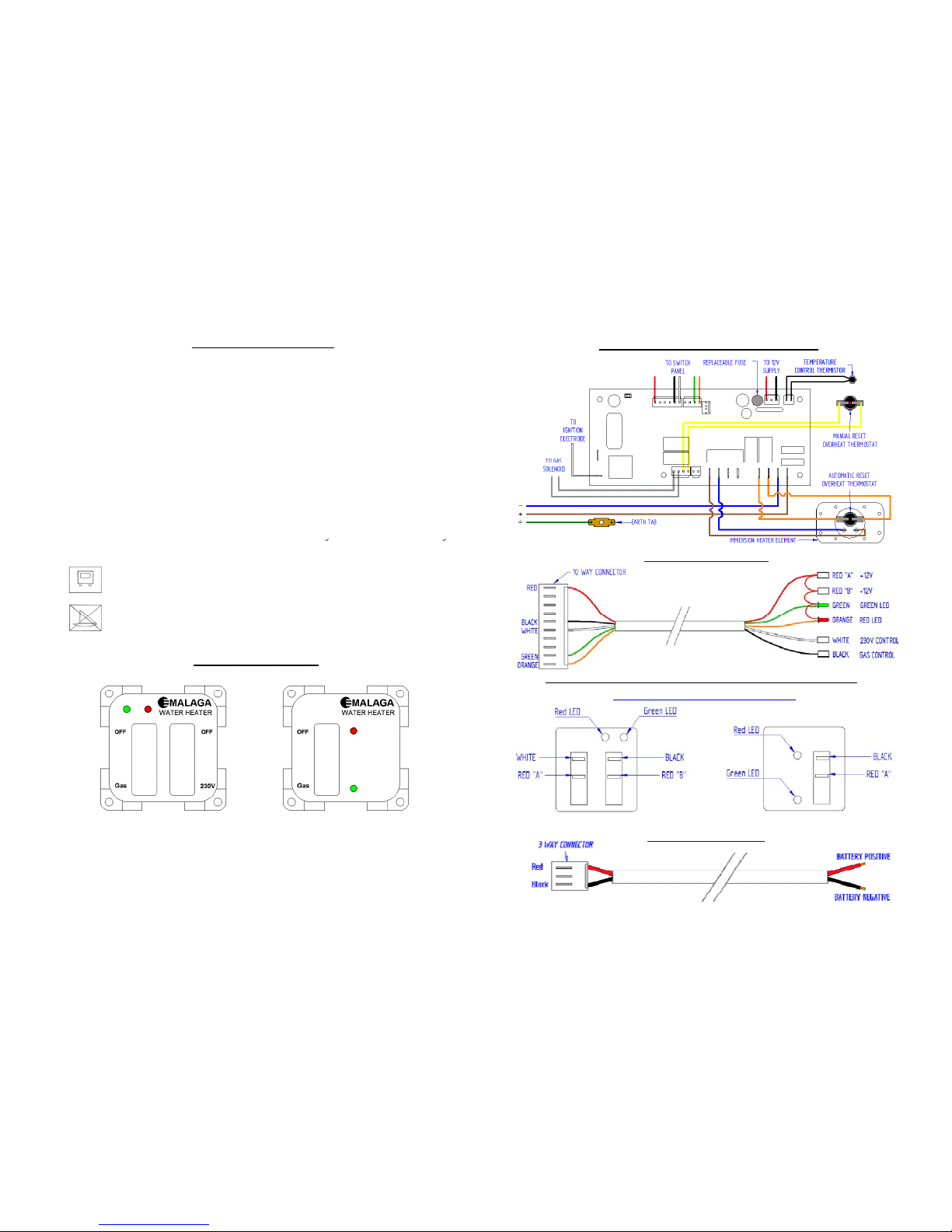
WIRING DIAGRAM MALAGA 5/5E
product
.
This appliance isnot intended for use by persons (including children) with reduced
physical, sensory or mental capabilities, or lack of experience and knowledge,
unless they have been given supervision or instruction concerning use of the
appliance by a person responsible for their safety. Children should be supervised to
ensure thatthey do no
t
p
lay with the appliance.
All warnings should be observed.
Incorrect use of the appliance and non observation of the installation and operator
instructions shall lead to the cancellation of the warrant
yand
exclusion of liabilit
y
y
y
claims. Only use the heater as directed by these instructions.
This symbol indicates that this appliance is suitable for use in Leisure
Accommodation Vehicles.
MALAGA 5/5E CONTROL LOOM
This
symbol
indicates
that
this
appliance
is
not
suitable
for
useinboats
.
CONTROL PANELS
Note: Malaga 5 (Gas only) does not have the white wire or the +12V “B” connection.
MALAGA 5/5E SWITCH PANEL CONNECTIONS
Malaga 5 E Control Panel
Malaga 5 Control Panel
MALAGA 5 /5E POWER LOOM
MALAGA 5E
MALAGA 5
-2 -
2 x 2 Position Switch
Green operation LED
Red lockout LED
1 x 2 Position Switch
Green operation LED
Red lockout LED
- 11 -
Page 3
TECHNICAL DATA
• Dimensions Height – 250mm
Width – 285mm
OPERATION INSTRUCTIONS
• The Propex Malaga 5 is for use on L.P.G. only.
Depth –520mm
• Weight empty 9.3kg
• Nominal Water capacity 13 Litres
• Inward protrusion from wall 480mm
• HEATING TIMES Gas Approx. 43 Mins
15
o
C– 70oC Gas & Electric Approx. 28 Mins
On initial operation or when the system has been drained, refill the system with
water and flush out by turning on each hot tap until a steady flow of water is
obtained. If a water filter is fitted it should be changed at the recommended
intervals.
•
The Propex
Malaga 5E is for use on both L.P.G. and mains electricity
.
Electric OnlyApprox. 64 Mins
• Standby consumption Gas 98W
• WATER - Maximum supply pressure 1.3 BAR
Pressure relief valve setting 3.0 BAR
Working pressure 2.0 BAR
•
Check that all the gas and electricity supplies are turned on.
GAS – Switch to the gas position on the control panel. Initially no LED will come
on and there will be a 10 second delay. Ignition will then take place and the green
LED will stay on as long as the burner is alight. If the gas does not light first time,
GAS
Heat input
1.25kW / 91g/h
Injector Bray 960 / 40
Gas connection 8mm / 5/16 o.d.
Gas type Butane 28-30mBAR
Propane 37mBAR
Pressure category & pressure I
3+
(28-30/37)
theignitorw
illswitchoff,th
egasvalve w
illcl
ose andthere w
ill
bea60
secon
d
delay before it tries again.
Note – When the water has reached the preset temperature the green LED will
switch off. As the water cools or is drawn off, the heater will automatically start
the above sequence again. If the red LED starts flashing it indicates a fault
condition
,
see faultfindingand lockouts.
I
3B/P
(30)
• ELECTRICITY –Malaga 5 12V DC
Malaga 5E 12V DC + 230V AC element
Element 750W
Current consumption @ 12V 0.36A
,
g
ELECTRICITY – The Malaga 5E has a 230V, 750W immersion heating
element. The operation of the immersion heater is controlled by the same
thermistor that controls the gas burner. If you wish to use the immersion heater
operate the 230V switch on the control panel. The immersion heater can be used
Note: If connecting to mains water supply, a suitable water pressure regulator
must be connected to ensure that the maximum supply of water pressure
does not exceed 190kPa (1.9bar)
Clearances required for installation and servicing, as seen from the inside.
Left Hand Side 240mm
Ri
g
ht Hand Side 100m
m
on
its
ownorsimultaneously
with
the
gas
burnertoachieve
a
quicker
heat
up
time.
Note – A 12V DC supply must be connected at all times.
SWITCHING OFF THE APPLIANCE – If the appliance is not in use it should
When not in use the
g
Top 5mm
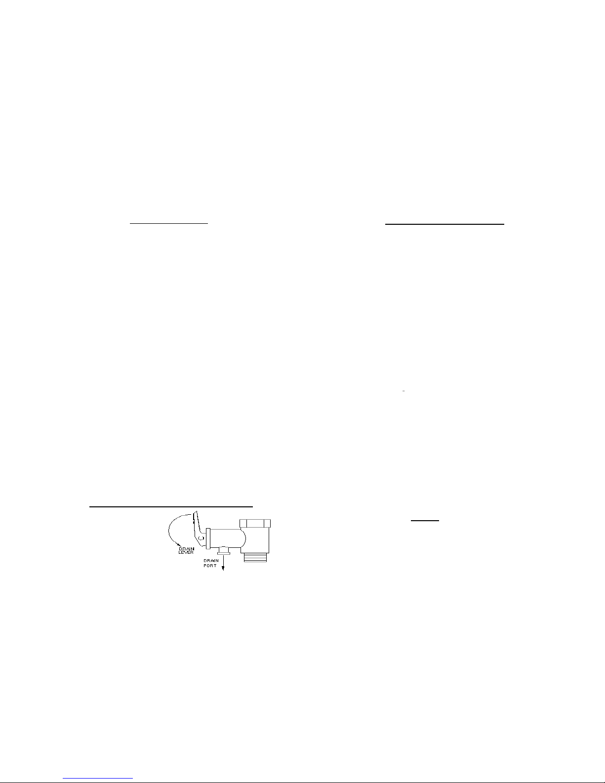
PRESSURE RELIEF/DRAIN VALVE
b
e switched off using the controlpanel. If the heateris notgoing tobeusedfora
long period of time the tank should be drained and gas supply isolated.
WATER – This appliance must not
be connected directly to the mains water
supply.
heater should be drained
using the drain valve as
per the diagram.
- 10 -
BATTERY – The h eater is designed to operate on a 12V DC supply. Should the
supply drop below 10V or rise above 15V, the gas valve will switch off and a
fault code of 3 flashes will be displayed on the control panel.
-3 -
Page 4

WINTER OPERATION – When using the heater in winter ensure the flue is
not blocked by snow or fallen leaves etc. When not in use make sure the heater
FAULT FINDING & LOCKOUTS
The heater is equipped with an electronic diagnostic system which will detect
fault conditions ranging from poor gas or DC supply to internal heater
is
drained
,
especially
during
the
winter
months
.
ENERGY FAILURE – in the event of an energy failure isolate the gas supply.
When the energy supply has been restored clear any lockouts which may have
occurred and continue normal operation.
malfunctions
.
In
the
eventofa
failure,the
red
LEDonthe
control
panel
will
flash
a number of times, pause, and repeat until switched off. Count the number of
flashes and refer to the table below.
Number
of Flashes
Fault Remedy
BLOWN
FUSE
–TheMalaga
MK5/5E
i
sequippedwitha
2
A
replaceablefuse
to protect the PCB in the event of an overload on the 12V circuit. This is easily
replaced and the location of the fuse is outlined on page 11.
1
No Flame
Detected
Check gas supply making sure there is gas in
the bottle and no blockage in the gas line.
Ensure propane is used at temperatures below
+5°C. Clear lockout as described below.
MAINTENANCE
To clean and sterilise inside the water heater use diluted sterilising fluid and
fully rinse through with clean water afterwards. The outside of the appliance
should not normally require cleaning. If it does, isolate the electrical supplies
and wipe down with a soft, damp cloth only. Allow to fully dry before
2 Overheat
Check there is water in the appliance. We
recommend you wait at least 5 to 10 minutes to
allow the heater to cool before clearing lockout
as described below.
Minimum operating voltage is 10V, maxi mum
reconnecting
the
electrical
supplies
.
If descaling of this appliance is required, this can be done using ‘Kettle Klear’ or
an equivalent product and fully rinse through with clean water afterwards.
The appliance should be checked and maintained (if required) periodically by a
competent person within a maximum of 2 years according to the practice in the
3
Low/High
Supply Voltage
is 15V, when measured at the heater. Check
battery voltage. If between 10V and 15V,
check connections between heater and battery.
Check alternator or external battery charging.
Clear lockout as described below.
country where it is used and these instructions.
We recommend annual testing of gas soundness and combustion by an
accredited LPG gas engineer.
5
Other / internal
fault
Attempt to clear lockout as detailed below. If
this fails, contact Propex directly.
Clearing Lockouts
Lockouts are cleared by moving the switch from on position to off position then
The
centre
pageofthis
booklet
showsanexploded
diagram
of
the
appliance
to
aid maintenance.
back
to the onposition. The complete sequence of switch movements mus
t
b
e
completed within 2.5 seconds for a lockout to be successfully cleared. If there is
air in the gas line, e.g. after a gas bottle change, the water heater may require
several attempts before it lights. If this does not clear the Overheat lock out
remove the front cover exposing the PCB and press the red button on the manual
-9 -
reset
overheat
thermostat
.
Note: A cycling of the power supply to the unit will not clear a lockout.
If problems persist contact Propex Heatsource Ltd on 023 8058 2555
-4 -
Page 5
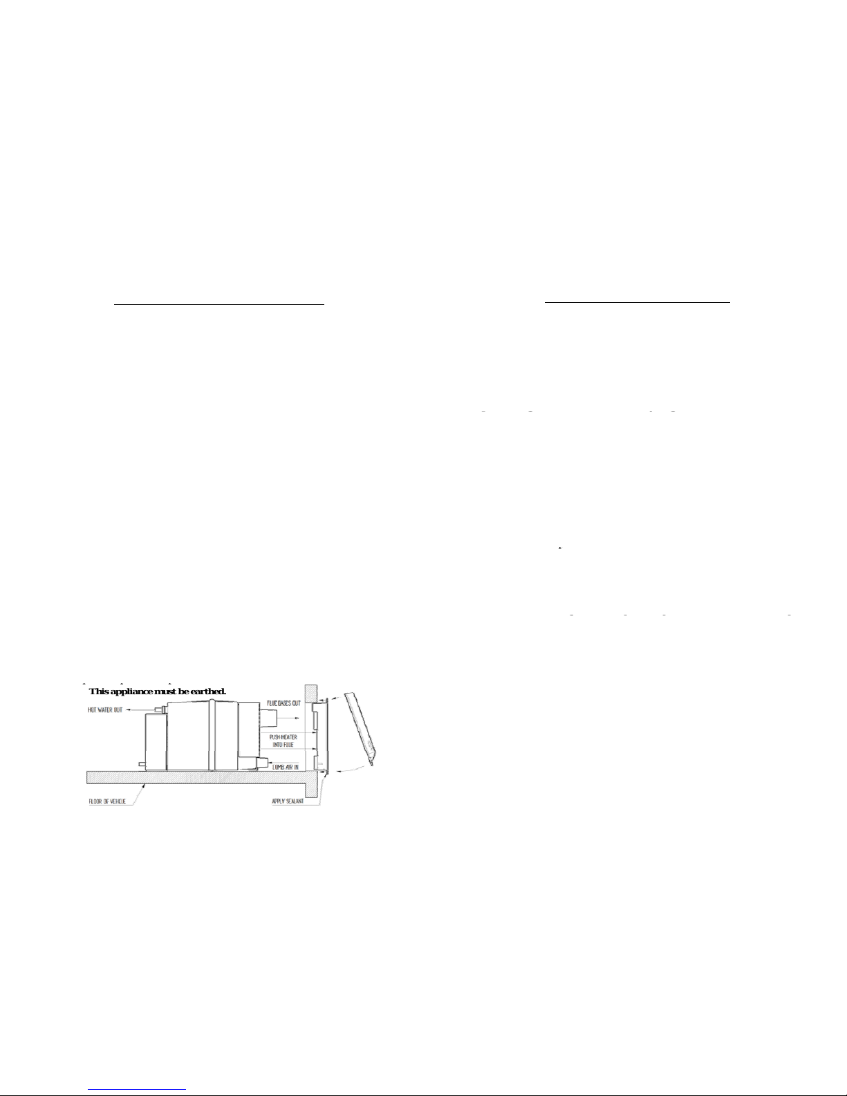
CONNECTING THE W ATER HEATER
When installing a non return valve should be fitted if necessary.
1. WATER: The Malaga 5 is fitted with 12mm plain stems to which a suitable
INSTALLATION INSTRUCTIONS
A competent person should install the appliance in accordance with the
appliance installation instructions and should consider any relevant
12mmpush
fit
connectors
shouldbefitted.Alternatively
you
can
also
use
12
mm I.D. reinforced, food quality, opaque or equivalent pipe with hose clips. It is
important that the hot and cold connections are connected correctly and if the
plastic inlet connection is removed, only a plastic replacement should be used.
IMPORTANT: The hot water outlet connection at the top of the tank must not
regulations
in
the
country
where
the
appliance
is
installed
.
For
this
appliance in Europe the standard is BS EN 1949:2002 (Specification for
the installation of LPG systems for habitable purposes in leisure
accommodation vehicles and in other road vehicles).
Installation and servicing of this appliance must only be carried out by
p
ersons registered with the Gas SafetyRegister(GB),or the relevant
b
e removedas
thish
ouses an a
dditi
ona
l
int
erna
l
tubewhich
p
rovidestheair
space for expansion inside the tank. The water pressure must not exceed 1.3 bar.
ALSO do not connect this appliance to a mains water supply.
Drain/Pressure Relief Valve – Drill the appropriate sized hole in the floor
close to the heater and run a piece of hose from the drain port, through the hole
pgyg(),
national organisation.
Prior to installation check the compatibility of the data plate information
with the LPG supply requirements of the vehicle.
This appliance must be installed in accordance with the current regulations.
to the outside. Seal round the hole with silicone orsimilarsealant.
Water Systems – The heater will work satisfactorily on either system where the
pump is controlled by a tap, micro-switch or pressure switch.
2. GAS: The gas fitting is 8mm (5/16”) and a suitable compression fitting is
required. An isolation tap should be fitted near to the heater and any
In
the
United
Kingdom
the
installation
mustbein
accordance
withBS6501
Pt 1 1978, BS5482 Pts 1 & 2 1977 and BS5440 Pt 2 1990.
The Malaga 5 Water Heater is designed to be floor mounted and flues
through a vertical section on an external wall. Normally the heater would be
fitted in a bed-box or locker allowing access to the heater with suitable room
fo
r
service andinspection. Structural sections within the vehicle shouldno
t
unsupporte
d
pi
pe-worksecured.
It
i
s recommende
d
that
agasdropholebe
positioned near to the heater and that all connections are carried out by a
registered person (see Installation section on page 3) .
3. ELECTRICITY: Fit the control panel in the chosen position and route the
loom down to the heater and plug into the PCB at CN27 & CN26. Connect the 2
p
be damaged. The flue terminal should not be fitted at the side of the
caravan/motor home where an awning may be fitted.
FLUE – Using masking tape, fix the template to the inside of the vehicle and
drill a pilot hole at position X. Remove the template and tape it to the outside
of the vehicle ensurin
g
thatthe template is square and thatthe centre lines u
p
core
loomtothe12v
supplyatCN24and
routetothe
heater
making
sure
the
polarity is correct. NOTE there is one less core on the loom used on the Malaga
5 and is supplied with a single on/off switch, whereas the Malaga 5E has 2 x 2
position switches to allow independent operation of gas or electric.
Malaga 5E only – The 3 core mains cable should be connected to a 230V AC –
5am
p
doublepole fused spur.
g
pqp
with the hole drilled from the inside.
Drill a 10mm hole at positions A and, using a jigsaw, cut out the hole. The
hole in the wall must be battened to secure inner and outer skins.
Note: When battening the finished hole must be 240mm x 135mm. Run a
bead of silicon rubber, or similar sealant, around edge of the rear side of the
ppp
Note: This appliance must be earthed.
flue
terminal
,
position
into
cut-outinwall
and
secure
with6screws
(No.8
x
¾”) provided and remove excess sealant. Clip the top of the flue cover onto
the flue terminal and secure with 2 screws (No. 6 x ½”) provided.
WATER HEATER – Remove the floor covering (e.g. carpet etc) from the
area where the heater will stand – 450mm inward from the wall and 320mm
-8 -
wide.Drawalineonthe
floor
from
the
centreofthe
flue,570mminto
the
vehicle. Slide the heater through the flue seals until the stop position is
reached. Make sure both flue and air intake pass through the lip seals.
Measure 115mm from right hand side of rear foot and line up with line on
floor – screw heater to the floor.
-5 -
Page 6
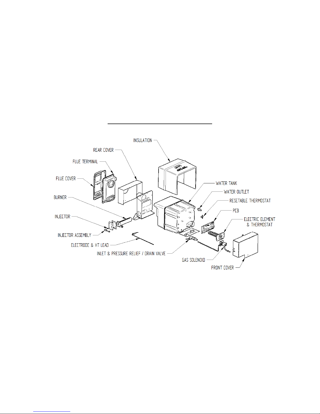
EXPLODED DIAGRAM OF MALAGA 5/5E
This diagram is to be used for reference when carrying out any maintenance on the appliance
.
Note: “ELECTRIC ELEMENT & THERMOSTAT” is only present on Malaga 5E. Malaga 5 will have a blanking plate in place of this
.
-6 - -7 -
 Loading...