

Page 1

Malaga 3/3E
Storage Water
Heater
INSTALLATION
&
OPERATION
INSTRUCTIONS
All gas appliances must be installed and/or
commissioned by corgi registered persons.
PROPEX HEATSOURCE LTD
Unit 5, Second Avenue Business Park,
Millbrook, Southampton,
United Kingdom, SO15 0LP
Tel: 023 8052 8555
Fax: 023 8052 8800
www.propexheatsource.co.uk
E.mail: [email protected]
1104 issue C
All Propex Heatsource Appliances are fully CE
marked and are tested by a notified body to the
relevant sections of the Gas Appliance Directive.
Page 2
USER INSTRUCTIONS
• The Propex Malaga 3 is for use on L.P. Gas only.
• The Propex Malaga 3E is for use on both L.P. Gas and mains electricity.
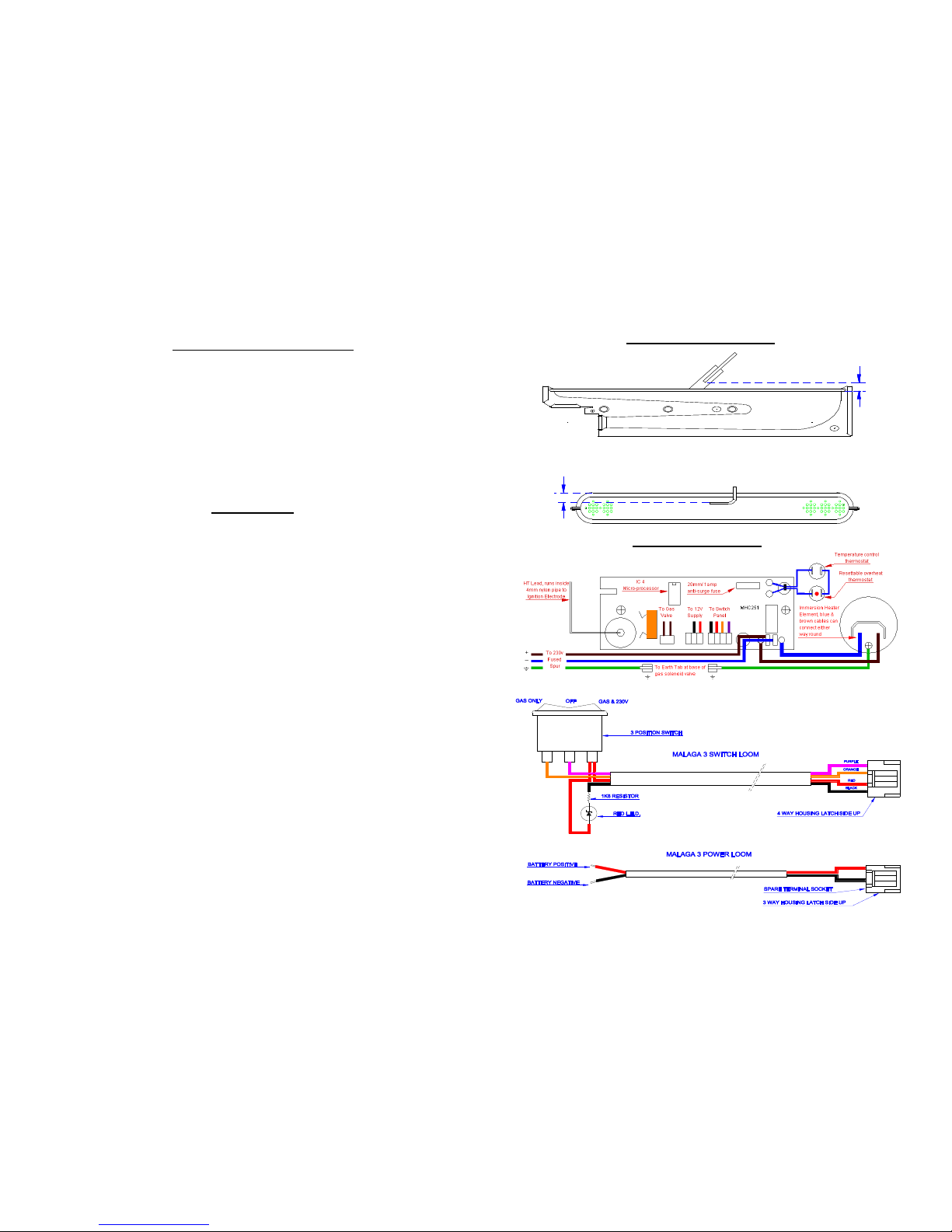
WIRING DIAGRAM
- 2 -
- 7 -
On initial operation or when the system has been drained, refill the system with water
and flush out by turning on each hot tap until a steady flow of water is obtained. If a
water filter is fitted it should be changed at the recommended intervals.
Check that all the gas and electricity supplies are turned on.
OPERATION
GAS – Switch to the gas only position on the switch panel. Initially the red light will
come on and there will be a 10 second delay while the micro-processor checks that
everything is ok. Ignition will then take place and the red light will stay on as long as
the burner is alight. If the gas does not light first time, the ignitor will switch off, the
gas valve will close and there will be a 60 second delay before it tries again.
Note – When the water has reached the preset temperature the red light will switch
off. As the water cools or is drawn off, the heater will automatically start the above
sequence again. If the red light starts flashing it indicates a fault condition, see fault
finding.
ELECTRICITY – The Malaga 3E has a 230v immersion heater which can be used
in addition to the gas burner. The operation of the immersion heater is controlled by
the same thermostat that controls the gas burner. If you wish to use the immersion
heater on its own the red light will start flashing 6 times after about 1minute. This
signifies that the burner is not alight but does not affect the operation of the
immersion heater.
Note – A 12v DC supply must be connected at all times.
WATER – This appliance must not be connected directly to the mains water supply.
BATTERY – The heater is designed to operate on a 12v dc supply. Should the
supply drop below 9v, the gas valve will switch off and a fault code of 6 flashes will
be noticed on the switch panel.
WINTER OPERATION – When using the heater in winter ensure the flue is not
blocked by snow or fallen leaves etc. When not in use make sure the heater is
drained, especially during the winter months.
3.5 / 4.5mm
7.0mm
3.5 / 4.5mm
7.0mm
ELECTRODE SETTING
Page 3
The Propex Malaga 3 and 3E water heaters are equipped with a self diagnostic
fault finding system. The system operates by flashing the red LED on the Malaga
switch panel a certain amount of times to indicate what the fault is. The light will
continue to flash while the switch is turned on. Some of the fault codes indicate
electronic faults in different parts of the printed circuit board, in which case the
frequency of the flashing light will only be useful to someone trying to repair the
circuit board.
2, 3, 4 & 5 flashes PCB Fault Replace MHC251 PCB
6 flashes Flame out Check gas supply
7 & 8 flashes Micro-processor Replace Micro-processor
CONNECTING THE WATER HEATER
1. WATER: The Malaga 3 is fitted as standard with John Guest Speed-fit stems
which take 12mm speed-fit pipe. Alternatively you can also use half reinforced,
food quality, opaque or equivalent pipe. It is important that the hot and cold
connections are connected correctly and if the plastic inlet connection is
removed, only a plastic replacement should be used.
IMPORTANT: The hot water outlet connection at the top of the tank must not
be removed as this houses an additional internal tube which provides the air
space for expansion inside the tank. The water pressure must not exceed 1.3 bar.
ALSO do not connect this appliance to a mains water supply.
Drain/Pressure Relief Valve – Drill the appropriate sized hole in the floor
close to the heater and run a piece of hose from the drain port, through the hole
to the outside. Seal round the hole with silicone or similar sealant.
Water Systems – The heater will work satisfactorily on either system where the
pump is controlled by a tap, micro-switch or pressure switch.
2. GAS: The gas fitting is 8mm (5/16”) and a suitable compression fitting is
required. An isolation tap should be fitted near to the heater and any
unsupported pipe-work secured. It is recommended that a gas drop hole be
positioned near to the heater and that all connections are carried out by a corgi
registered person.
3. ELECTRICITY: Fit the switch panel in the chosen position and route the 4
core loom down to the heater and plug into the PCB. Connect the 2 core loom to
the 12v supply and route to the heater making sure the polarity is correct.
Malaga 3E only – The 3 core mains cable should be connected to a 230v AV –
5 amp fused spur.
Note: This appliance must be earthed.
- 4 -
FAULT FINDING – CHECK LIST
- 5 -
DETAILED FAULT FINDING
1. HEATER NOT WORKING – L.E.D. DOES NOT LIGHT UP.
Check red button in middle of overheat thermostat and 1amp anti-surge fuse on
circuit board. If none of these, check continuity across thermostats and wiring
connections including the terminal housings that plug onto the PCB.
2. L.E.D. COMES ON BUT THE HEATER DOES NOT LIGHT.
After 10 seconds, you should be able to hear the gas solenoid valve open, and the
ignitor start sparking. If no valve, wait for the 2 ignition cycles to complete and
count the number of times the red L.E.D. flashes. If it flashes 2,3,4 or 5 times
it indicates a fault on the PCB. If 6 flashes are observed, disconnect valve from
PCB and apply 12V, if it does not work get it replaced. If there is no spark, this
can be either a PCB fault or a faulty HT lead between the ignitor and ignition
electrode. If the solenoid opens, and the ignitor is sparking correctly there has to
be a gas supply problem which could be a blocked jet, blocked pipe or faulty
regulator.
3. HEATER LIGHTS BUT GOES OUT AFTER 5 SECONDS.
This condition will also end up with a 6 flash fault code and is due to the flame
signal not getting to or not being recognized by the electronics. Firstly, make sure
the left hand PCB mounting screw is connecting the board securely to the tank.
Check the HT lead to make sure the terminal is not broken, or that the lead itself is
not damaged. The other causes could be that the electrode is not fully in the flame,
the flue terminal is incorrectly fitted, or that there is an electronic fault on the
PCB.
BEFORE UNDERTAKING ANY OF THE TESTS BELOW CHECK GAS
PRESSURE, 12V DC SUPPLY, 230V SUPPLY (MALAGA E) AND
THAT THERE IS A STEADY SUPPLY OF WATER AT THE HOT TAPS.
Page 4
• TECHNICAL DATA
• Dimensions Height – 250mm
• Width – 285mm
• Depth – 520mm
• Weight empty 9.3kg
• Inward protrusion from wall 480mm
• WATER – Maximum supply pressure 1.3 BAR
• Pressure relief valve setting 3.0 BAR
• Working pressure 2.0 BAR
• GAS Heat input 1.15kw / 80g/h
• Injector Bray 960 / 40
• Gas connection 8mm / 5/16 o.d.
• Pressure setting CAT I3+ Propane 30/37 mbar, Butane 28/30 mbar.
• ELECTRICITY – Malaga 3 12v DC
• Malaga 3E 12v DC + 230v AC element
• Element 750W
• Current consumption @ 12v 0.36A
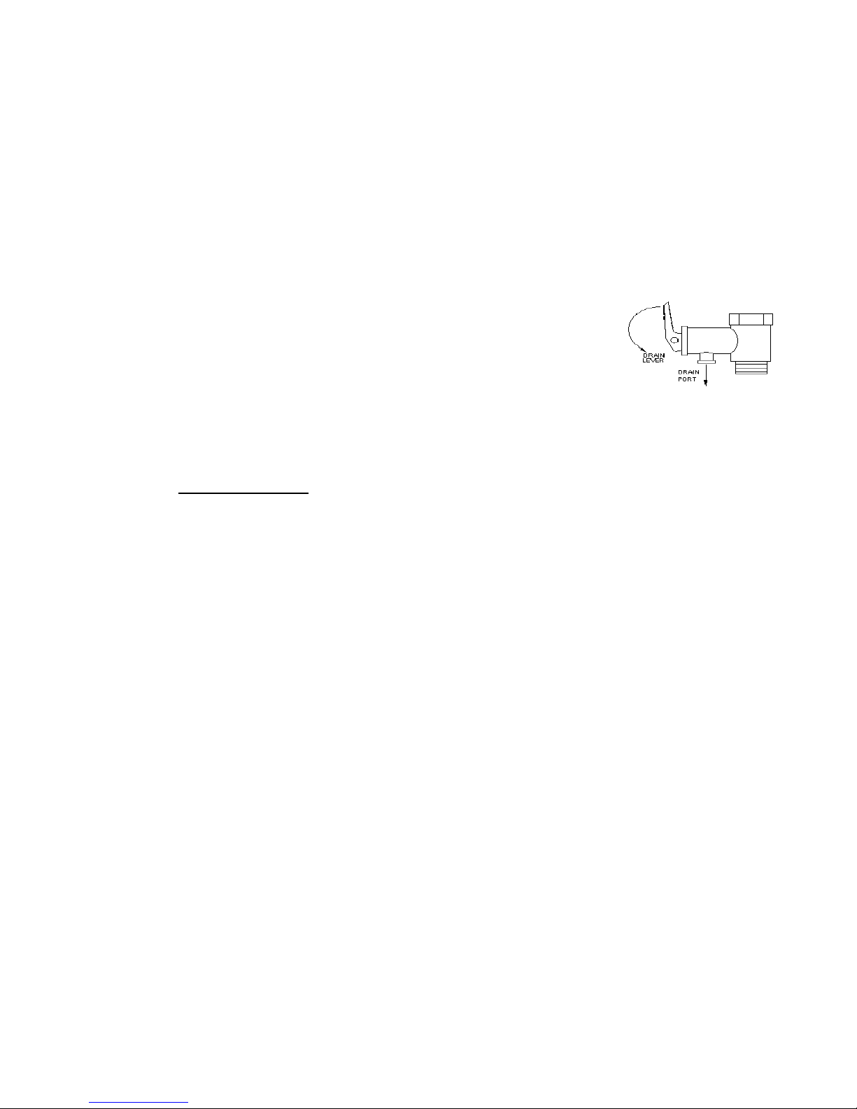
When not in use the
heater should be drained
using the drain valve as
per the diagram.
- 6 - - 3 -
INSTALLATION
Installation and servicing of this appliance must only be carried out by Corgi
registered persons.
Prior to installation check that the gas supply pressures & type are
compatible. (see data label on appliance)
This appliance must be installed in accordance with the current regulations.
In the United Kingdom the installation must be in accordance with BS6501
Pt 1 1978, BS5482 Pts 1 & 2 1977 and BS5440 Pt 2 1990.
The Malaga 3 Water Heater is designed to be floor mounted and flues
through a vertical section on an external wall. Normally the heater would be
fitted in a bedbox or locker. Structural sections within the vehicle should not
be damaged.
FLUE – Using masking tape, fix the template to the inside of the vehicle and
drill a pilot hole at position X. Remove the template and tape it to the outside
of the vehicle ensuring that the template is square and that the centre lines up
with the hole drilled from the inside.
Drill a 10mm hole at position A and, using a jigsaw, cut out the hole. The
hole in the wall must be battened to secure inner and outer skins.
Note: When battening the finished hole must be 240mm x 135mm. Run a
bead of silicon rubber, or similar sealant, around edge of the rear side of the
flue cover, position into cut-out in wall and secure with screws.
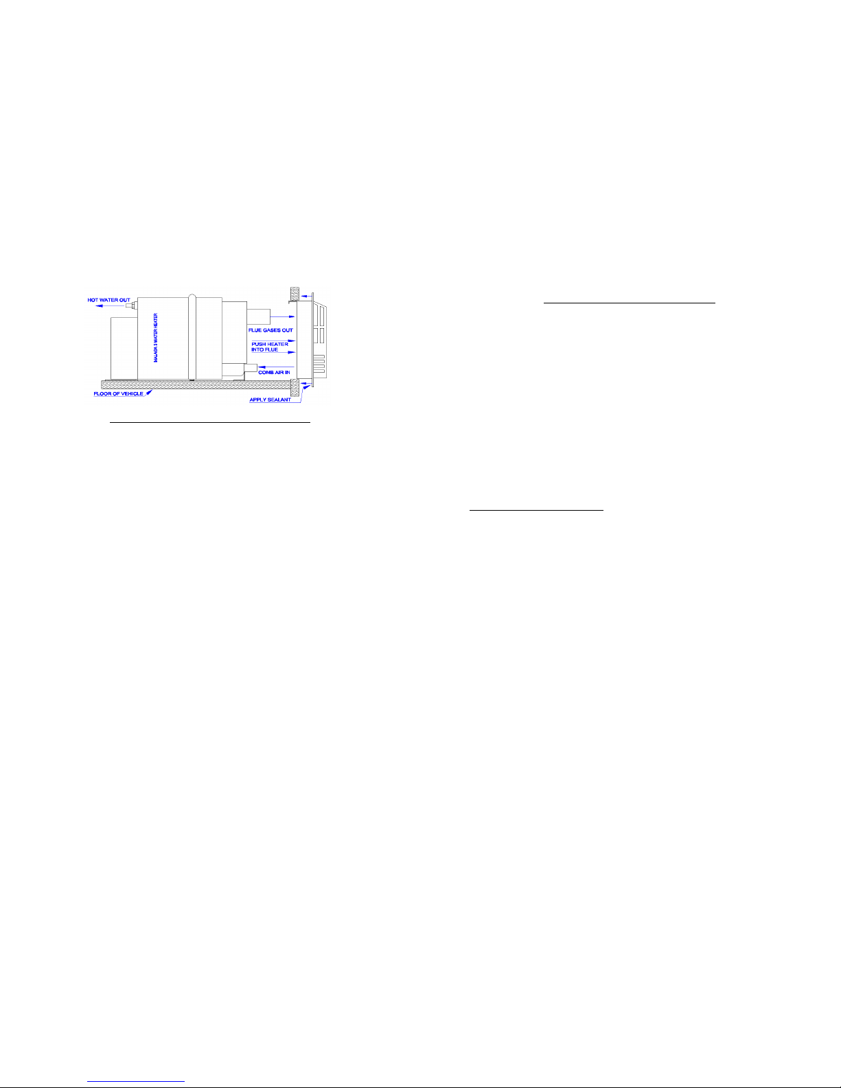
WATER HEATER – Remove the floor covering (e.g. carpet etc) from the
area where the heater will stand – 450mm inward from the wall and 320mm
wide. Draw a line on the floor from the centre of the flue, 570mm into the
vehicle. Slide the heater through the flue seals until the stop position is
reached. Make sure both flue and air intake pass through the lip seals.
Measure 115mm from right hand side of rear foot and line up with line on
floor – screw heater to the floor.
Clearances required for installation and servicing, as seen from the inside.
Left Hand Side 240mm
Right Hand Side 100mm
Top 5mm
4. WATER DOES NOT HEAT UP WHEN 230V IS SWITCHED ON.
If the gas/230v position is selected on the switch panel, and the gas supply to the
heater is switched off, the water should heat up even though the red light on the
switch panel will be flashing 6 times. If not, get an electrician to check that there
is 230V AC on the terminals of the immersion heater. If there is a supply, switch
off the 230V, disconnect the brown lead and read the resistance across the element
terminals which should read 70 ohms. If there is no reading, i.e. open circuit, replace
the element. If the element is OK, there is a dry boil thermostat in the element
housing, but this resets itself when it cools down.
If there is no 230V AC supply to the element, check the fuse in the fused spur. If the
fuse is ok, the PCB must have a faulty element relay and will need replacing.
 Loading...