


OPERATING AND MAINTENANCE MANUAL
P5000 EM
MICRO-PERCUSSION MARKING MACHINE
ELECTROMAGNETIC VERSION
Ref. 92198 - P5000 EM_en_C - Last updated: 06/2009
Pro-Pen reserv es all rights to modify i ts products.
This document is non contractual.
www.pro-pen.com

Table of conten ts
A - Introduction ................................................... ......... .... .... .... ........... .... .... .... ......... .... ........4
1. Forewa rd ............. .. ............ .. ............ .. ........... ... .. ........... ... ........... .. ............ .. ... ........... ..............................4
2. Unpack in g ......... .. ............ .. ........... ... ........... .. ... ........... .. ............ .. ............ .. .. ............ .. ..............................5
Storage .............................................................................................................................................. 5
Handling the machine .......................... .. .. ................................. .. .................. .. ..................................6
Installa tion ........ ................. ................ ............. ................ ................ .............. ..................................... 6
3. Identification of the marking equi pment ................................ ................ ................ ................ ..................6
4. Power .............. .. ........... ... ........... .. ... ........... .. ............ .. ............ .. .. ............ .. ........... ... ................................ 6
5. Regulat io n ob s e rv a n c e . ............ .. ............ .. .. ............ .. ........... ... ........... .. ............ .. .. ............ .. .....................6
Declar a tio n o f com p liance CE ...... ........... ... ........... .. ... ........... .. ............ .. ............ .. ........... ... .. ..............6
Declaration of compliance to other directives ...................................................................................7
Declar a tio n o f com p liance to nor ms .. .. .. ............ .. ........... ... ........... .. ... ........... .. ............ .. ............ .. . ......7
6. Work sta tio n sa fety .......... .. ........... ... ........... .. ... ........... .. ............ .. ............ .. ........... ... ................................8
7. Warranty conditions and operating instructions .....................................................................................9
B - Operating instructions for the machine ........................................................................1 0
1. Descr ip tio n o f th e mac h in e ..... .. .. ............ .. ........... ... ........... .. ... ........... .. ............ .. ............ .. .....................10
2. Technic a l S pe c if ic a tions .. ........... .. ............ .. ............ .. .. ............ .. ........... ... ........... .. ... ..............................11
3. Physica l ch a racterist ic s ..................... .. ............ .. .. ............ .. ........... ... ........... ... ........... .. ... .......................11
4. Dimensional drawings ..........................................................................................................................11
Dimensional drawings of the machine: P5000EM + EM1/C .......... .................. ................. .. .............11
Dimensional drawings of the table ..................................................................................................12
5. List of accessories available upon request ........... .............. .............. .............. .. .............. ......................13
C - Functional definitions ...................................................................................................1 6
1. Circuit connections for the unit ...................................... .............. ............................ .............................16
2. Inside view of the marking head .............................. .. .............. .. .............. .. .............. .............. ...............16
3. Connec ti o ns fo r a cc e s s o rie s .. .. .. ............ .. ........... ... ........... .. ............ .. .. ............ .. ............ .. .....................17
D - Installation ...................................................................................................................18
1. Install at io n .. .. ... ........... .. ............ .. ............ .. .. ............ .. ........... ... ........... .. ............ .. .. .................................18
2. Connec ti o ns ........ .. ............ .. ............ .. ........... ... .. ........... ... ........... .. ............ .. ... ........... .. . .........................18
Safety precautions ..........................................................................................................................18
View of connectors ..........................................................................................................................18
Keyboard connection ...................................... ................ ................ .............................. ..................19
Compressed air connection (in the event of the stylus cooling by compressed air) .......................19
Power supply connection ....................... .............. .............. .............. ............................. ..................19
Grounding connection .............. ................ .......................................................................................20
3. Coordin a te sy s te m ....... ... ........... .. ............ .. ............ .. .. ............ .. ........... ... ........... .. .................................20
4. Hold the p a rt to be m a rk e d ..... .. .. ............ .. ........... ... ........... .. ... ........... .. ............ .. ............ .. .. . ..................21
5. Adjusting the height of the stylus ..........................................................................................................21
6. Definition of operating distances of a stylus ............................................ .. .............. .. ...........................22
7. Using the P 05 p ro g ra m ....... ... ........... .. ............ .. .. ............ .. ........... ... ........... ... ........... .. ... .......................22
E - Marking depth ....... ............................................................................................... ........23
1. Factors influencing marking depth ..................... .. .............. .............. ....................................................23
Choosing the stylus .............................................................. .............. .. .............. .. ...........................23
Distance between the stylus and the part .......................................................................................24
Marking force ..................................................................................................................................25
Choosing the marking speed ............................................................. .. ............................ .. .............25
2. Marking depth .......................................................................................................................................25
F - Preventive maintenance ..............................................................................................26
1. Every we e k ...... .. ........... ... ........... .. ... ........... .. ............ .. ............ .. ........... ... ........... .. .................................26
2. Every three months .... ............ .. ........... ... ........... .. ............ .. ........... ... .. ............ .. ........... ... .......................26
3. Every two y ea r s ..... ... ........... ... ........... .. ............ .. .. ............ .. ........... ... ........... ... ........... .. .. ........................27
Ref. 92198 - P5000 EM_en_C
2/34

G - General maintenance .................................................................................................. 28
1. Genera l in fo rmation .................. .. ............ .. ........... ... ........... .. ... ........... .. ............ .. ............ .......................28
2. Detaching the point of the stylus for sharpening ......... .............. .............. .............. ...............................28
3. Changin g th e fu se ............. .. ............ .. ........... ... ........... .. ... ........... .. ............ .. ............ .. ............................29
4. Cleaning the sensors ............................................................................................................................29
H - Resolution of the problems ..........................................................................................30
1. Possible marking problems and problem resolution .............................................................................30
2. What to do if... ....... ............ .. ............ .. .. ............ .. ........... ... ........... .. ............ .. ... ........... ............................31
I - Wearing and spare parts .......................... .... .. ....... .... .... .. .... .. ......... .. .... .. .... ....... .... .. .... ..32
1. Spare pa rt s ...... .. .. ............ .. ........... ... ........... .. ............ .. .. ............ .. ............ .. ........... ... ..............................32
2. Consuma b l e s ........ ... .. ............ .. ........... ... ........... .. ... ........... .. ............ .. ............ .. ........... ... .......................32
J - Noise emission of the machin e ....................... .................................... .........................33
1. Test code .. .. ........... ... ........... ... ........... .. ............ .. .. ............ .. ........... ... ........... ... ........... ............................33
Measurement method .....................................................................................................................33
Definition of the microphone position ............ ................ .. ................................ ................................33
Test cond itions . ............ .. ............ .. ........... ... .. ........... ... ........... .. ............ .. ............ .. .. ..........................33
2. Noise emission information .... .. ........... ... .. ........... ... ........... .. ............ .. .. ............ .. ............ .. .....................33
K - Appendix ......................................................................................................................3 4
Ref. 92198 - P5000 EM_en_C
3/34

AIntroduction
1. Foreward
Before reading this manual, view th e star t-up CD ROM and try to execut e the test ma rking sug gested. The n, read
through the whole manual.
The P5000 EM is designed for marking applications. If used for other purposes, Pro-Pen cannot guarantee the
quality of the result. Pro-Pen is not responsible for damage caused by inappropriate use of the machine.
Four icons indicate important points:
Work station safety
Indicates differe nt safet y pr ecautions to be t aken d uring i nst all ation and oper ation of
the machine.
Instructions for use and warranty lim itations
Indicates different operati ng procedures which respect warranty condit ions.
A
Operating instructions
These tips help optimize the machine’s perfor ma nce.
What to do if...
This icon refers to t he last chapter which describes the acti ons to be carried out in the
event of a problem or breakdown on the marking equipment.
Ref. 92198 - P5000 EM_en_C
4/34

2. Unpacking
AIntroduction
A
P5000EM: weight: 34 kg (74.957 lb)
If it is necessary to unpack the machine without the aid of a mechanical lift, it is
recommended to use two persons wearing safety shoes.
1 : Cover
2 : Wedge
3 : Wedge
4 : Wedge
5 : P5000
6 : option
7 : Contents of the box: keyboard
8 : Box + pallet
9 : Contents of the box: accessories provided: 1 technical document on CD ROM, stylus...
Storage
Keep the packing in case the machine has to be retur ned.
Ref. 92198 - P5000 EM_en_C
5/34

AIntroduction
Handling the machine
Take the machine out of its package before hooking it to a mechanica l lift. Unpack the
machine with 2 operators.
There is an M10x20 handling hole on the top of the P5000. Use a lifting ri ng capable of sustaining 230 DaN
(517.061 lb) to conform with standard NFX35-109. Pro-Pen can provide an M10x20 ring as an opti on (Ref.
MCM08/3140).
Installation
• Unpack the machine with 2 operators. Put the machine on its feet.
• The hand crank must not cover the M10x20 hole located on the top of the column (Z axis).
• Screw the lifting ring fi rmly and completely into the column.
• Use the lifting ring to carry the machine to its installation location.
3. Identification of the marking equipment
The marking equipment is identified by:
A
• 1 identifcation plate on the marking head
Have the model and serial number of the equipment available when contacting Pro-Pen.
4. Power
• power supply: 115 V / 230 V
• pow er: 360 W
• frequency: 50 -60 Hz
5. Regulation observan ce
Manufacturer, GravoTech Marking SAS - 56 avenue Jean Jaurès BP 80015 - 10604 LA CHAPELLE SAINT LUC France (head office) declares:
Declaration of compliance
CE marking on the equipment attests the observance of the following European directives:
• Directive 98/37/EC of the Europe an Parl iament and of the Council of 22 June 1998, concerning the consolidation of the laws of member states relating to the machines.
• Directive 2006/95/EC of the European Parliament and of the Council of 12 December 2006 on the harmonisation of the laws of the Member States relating to electrical equipment designed for use within certain voltage
limits.
• Directive 2004/108/EC of the European Parl iament and of the Council of 15 December 2004 on the harmonisation of the laws of the Member S tates relating to electromagnetic compatibility.
Ref. 92198 - P5000 EM_en_C
6/34

AIntroduction
Declaration of compliance to other directives
Equipment is compliant with the following European directives:
• amended Directive 2002/95/EC of the European Parliament and of the Council of 27 January 2003 restricting
the use of some dangerous substanc es present in electrical and electronical equipment (RoHS).
• amended Directive 2002/96/EC of the European Parliament and of the Council of 27 January 2003 on waste
electrical and electroni c equipment (WEEE).
Waste Electronic and Electrical Equipment
This symbol indicates that once this equipment has reached the end of it s useful life, it must not be
disposed of with non-sorted municipal waste, in accordance with European Directive 2002/96/EC.
The equipment must be disposed of at an appropriate collection point for process ing, sorting, and
recycling of W aste Electronic and Electrical Equipment (WEEE).
The elements which compose Waste Electronic and El ectri cal Equi pment (WEEE) may con tai n subst ance s which
have harmful effects on the environment or on human health.
By following these instruction s, you are helping the environment, contribut ing to the preservation of our natural
resources, and protecti ng human h ealt h.
Declaration of compliance to norms
A
The equipment is compliant with the following norms:
• St andard NF EN 61 000-6 -2 of January 2006 c oncerni ng elect romag netic compati bil ity (EMC) - Part 6-2 : generi c
standards- Immunity for industrial environments.
• St andard NF EN 61000-6-4 of March 2007 concerning el ectromagnetic compatibility (EMC) - Part 6-4: generic
standards- Standard on emissions for industrial environme nts.
The modification or transformat ion of this equipment, adapt ation and accessory
installation unre commended by Pro-Pen modify this equip ment’ s characteri stics and
therefore void the compliance with the applicable EU direct ives. These modificatio ns
void Pro-Pen’s liability. In this case, the machine and equipment installer is
responsible for the final work st ation’s compliance.
Ref. 92198 - P5000 EM_en_C
7/34

AIntroduction
6. Work station safety
To ensure security and productivity, read this manual before starting-up the equipment.
A
• This marking equipment is designed to functi on at a room temperature between 5
0
F) to 45 0C (113 0F).
• Do not use this marking equipment in an explosive environment.
• Grounding must be done according t o the regulations in ef fect to ensure the safety of the
personnel. The connection to the single phase power supply is made with a standard, 3
pin plug with grounding. It must be equipped with an adequately calibrated 30 mA
differential cut-off and protection device.
• This marking equipment is not designed to operate in damp premises.
• During marking, do not place fingers or object s in the area reserved for sty lus movement.
Keep hands away from the marking zone. Disregard for this recommendation may result
in the operator being light ly pinched by the point of the stylus.
• Depending on the application (tooling or heavy parts), it is re comme nded to wear safety
shoes and work gloves.
• Do not remove the power supply cover: electrification risk.
• In case of a long marking cycle or fast pace, the stylus’ temperature can reach 100
0
(212
F). Beyond this temperature, the system is in security mode. Use a cooling system
in a high temperature environment .
• The air exhaust from the stylus can project metal dust or chips, if necessary wear safety
glasses (in the event of the styl us cooling by compressed air).
0
C (41
0
C
At the time of disposal, wearing personal protective equipment (PPE) is
recommended to dismantle the mechanical elements of the machine. Some guiding
elements (pinions, bearings, bars) are dismantled while hot and may release toxic
fumes.
Ref. 92198 - P5000 EM_en_C
8/34

AIntroduction
7. Warranty conditions and oper atin g instructions
This equipment is designed to mark material using Pro-Pen electromagnetic styli only. Any other use, or the use
of styli other than those provided by Pro- Pen is not recommended. Pro-Pen will not be held responsible for the
results.
• The compressed air system must meet all standards (in the event of the stylus cool ing by
compressed air).
• Never lubricate any part of the stylus or carriage guide bars.
Pro-Pen will not be held responsible for injuries resulting from disregard for the above operating instructions or
other general safety rules applicable to the use of this equipment. Furthermore, di sregard for the instructi ons wil l
void the warranty.
When marking or doing test marking, the styl us must always have a p art under it wi th
which to make contact.
If it strikes only air, these are the risks:
• mechanical deterioration of moving parts
• void of the manufacturer’s guarantee
A
For more information, please refer to the warranty details delivered with the machine.
Ref. 92198 - P5000 EM_en_C
9/34

BOperating instructions for the machine
1. Description of the machine
The P5000 EM is a digitally controlled micro-per cussion marking machine.
The marking head is attached to a column stand wit h a Z axis. The Z axis is adjusted manually using the crank
handle and the ruler along the frame for positioning.
This machine works by moving the stylus along the X and Y axes of a grid.
The control electronics and the screen are integrated.
This combination of technologies all ows for rapid marking of alphanumeric characters and logos.
The LCD screen is located on the front of the machine. The same keyboard used for a PC connects to the top of
the marking head.
As an option, a PC linked to the control board by an RS232 connecti on, can be used to manage marking thank s to
the program developed in a Windows® environment.
1
B
2
3
4
5
1 : Z axis crank handle
2 : Ruler
3 : Marking head
4 : LCD screen
5 : Electromagnetic stylus
6 : CAN plug
6
Ref. 92198 - P5000 EM_en_C
10/34

AOperating instructions for the machine
2. Technical Specifications
• marking area: 100 mm (3.937 in) x 120 mm (4.724 in)
•stylus EM1/C
• fonts available:
- continuous action, dot by dot: norme 5x7
- size: from 0.5 mm (0.02 in) to 100 mm (3.937 in) mm with increments of 0.1 mm (5/1000 in)
- characters: those included in the basic multilingual diagram of the Unicode standard (ISO 10646)
• dates, counters, bat ch numbers, shift codes, logos...
• maximum movement speed: 300 mm (11.811 in) per second
• max. height of the part to be marked (stylus EM1/C): 289 mm (11.378 in)
3. Physical characteristic s
• dimensions (L x w x h): 601 mm (23.661 in) x 327.5 mm (12.894 in) x 734 mm (28.898 in)
• weight: 34 kg (74.957 lb)
4. Dimensional drawings
B
Dimensional drawings of the machine: P5000EM + EM1/C
1 : Marking area: 100 mm (3.937 in) x 120 mm (4.724 in)
2 : CAN plug
3 : Electromagnetic stylus: EM1/C
Ref. 92198 - P5000 EM_en_C
11/34
AOperating instructions for the machine
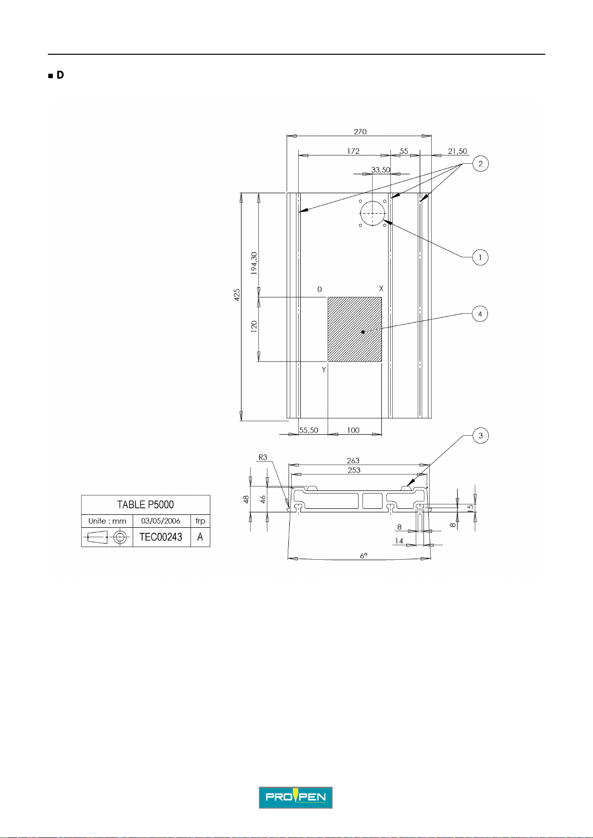
Dimensional drawings of the table
B
1 : Column axis
2 : T-slot
3 : Anti-skid pads
4 : Marking area: 100 mm (3.937 in) x 120 mm (4.724 in)
Ref. 92198 - P5000 EM_en_C
12/34

AOperating instructions for the machine
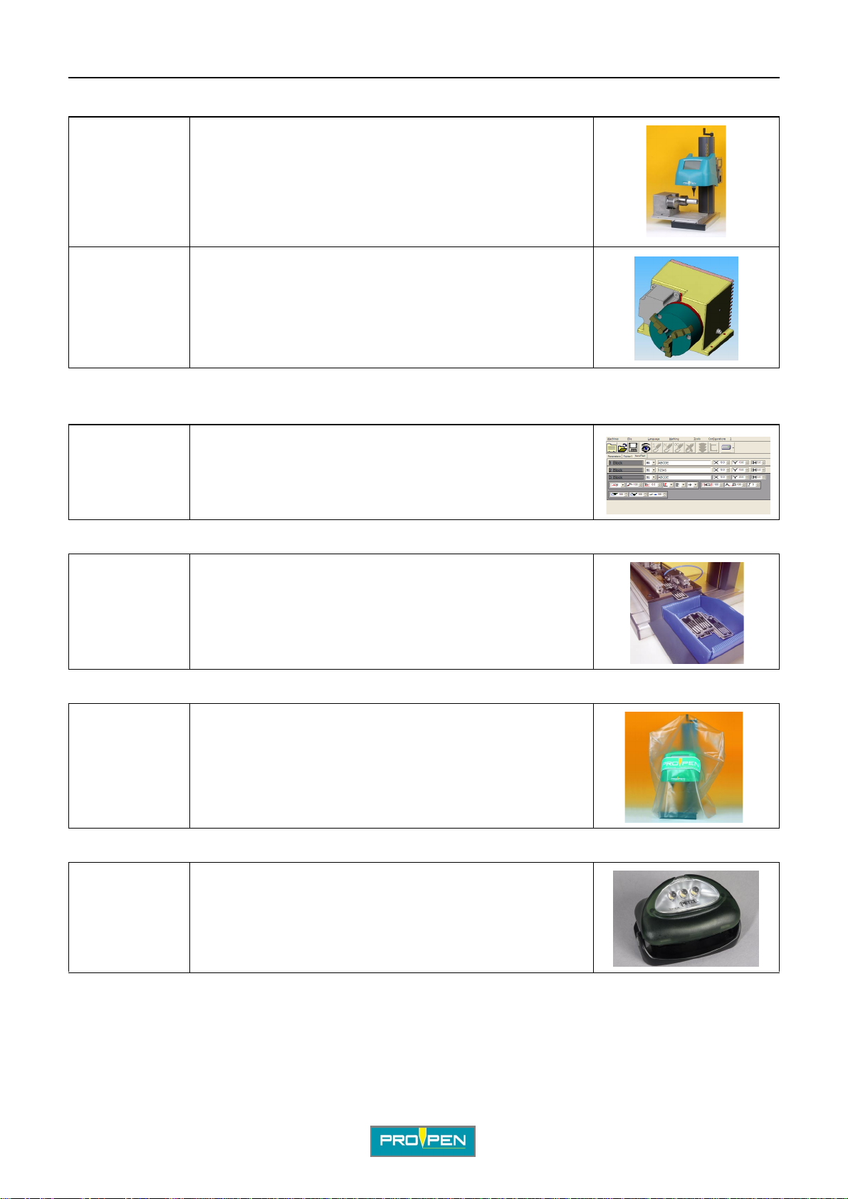
5. List of accessories avai la bl e up on request
Start cycle foot pedal
Ref. 25053
• office footswitch :
A simple touch of the pedal will launch a marking "n" times, leaving
the operator with both hands free. The foot pedal is not designed to
stop marking.
B
Ref. 25054
Button box for start cycle/emergency stop
Ref. 25055
Plate holder
Ref. 2509
• industrial footswitch:
Same use as described above. This foot pedal is especially
designed for industrial wor k environments or for high rate production .
Unlike the office footswitch, a double action avoids untimely
triggering.
• The green button is used to launch marking (same function as the foot pedal).
• The red button is used to stop either a single marking in
progress or a series of markings before it reaches the end.
After pushing the emergency stop button, the gree n button cannot be used to restart
marking. In this case, use the keyboard.
• sound-proof plate holder:
This accessory reduces the noise level during marking.
Ref. 25153
Magnetic plate clamp
Ref. 2508
Ref. 92198 - P5000 EM_en_C
• raised plate holder:
This accessory is used to be able to mark plates without having to
take down the DP3500/TAG3500 accessory.
• As a complement to the sound-proof plate hold er, it is used to clamp parts on a steel suppor t.
13/34
AOperating instructions for the machine
Circular marking device
Ref.
25170 LXX
• DP3500:
This accessory is used to rotate a part under the marking head in
order to mark the circumference.
Maximum moment of inertia of the part:
• without chuck: 65 kg.cm
• with chuck: 50 kg.cm
B
2
2
Ref.
25180 LXX
Program PW05
Ref. 25158
Ref. 25159 (USB)
TAG 3500
Ref.
25178 LXX
• DP4500:
This accessory is used to rotate a part under the marking head in
order to mark the circumference.
• Developed in a Windows environment, this program
combines all the capabilities and user-friendl iness of a PC.
• An unlimited number of files can be seen on the screen.
• Exists with a USB or parallel prot ecti on key.
• This accessory is used to automatically feed identification plates to the machine.
Protective cover
Ref. 2743
• This accessory is used to protect the machine from dust.
Marking zone lighting
Ref. 25154
• This accessory is used to light the marking area using a
high power LED lodged under the marking head.
Ref. 92198 - P5000 EM_en_C
14/34

AOperating instructions for the machine
Other accessories
Ref. 2427 Electromagnetic stylus: EM1/C
Ref. 2685 Points for EM1/C stylus: 90°
Ref. 92101 1 instruction card
Ref. 92198 Operating and maintenance manual
Ref. 2620 Stainless steel plates in credit card format, pack of 50
Ref. 25121 Bar code reader Scanplus 1800SR [reads 10 cm (3.937 in)]
Ref. 25122 230 V power supply for bar code reader
Ref. 25124 115 V power supply for bar code reader
B
Ref. 92198 - P5000 EM_en_C
15/34

CFunctional definitions
1. Circuit connections for the unit
1
2
C
3
1 : Keyboard connection
2 : Bus CAN
3 : CPU card
4 : LCD screen
2. Inside view of the marking head
4
1
1 : X motor
2 : Y motor
Ref. 92198 - P5000 EM_en_C
2
16/34
AFunctional definitions
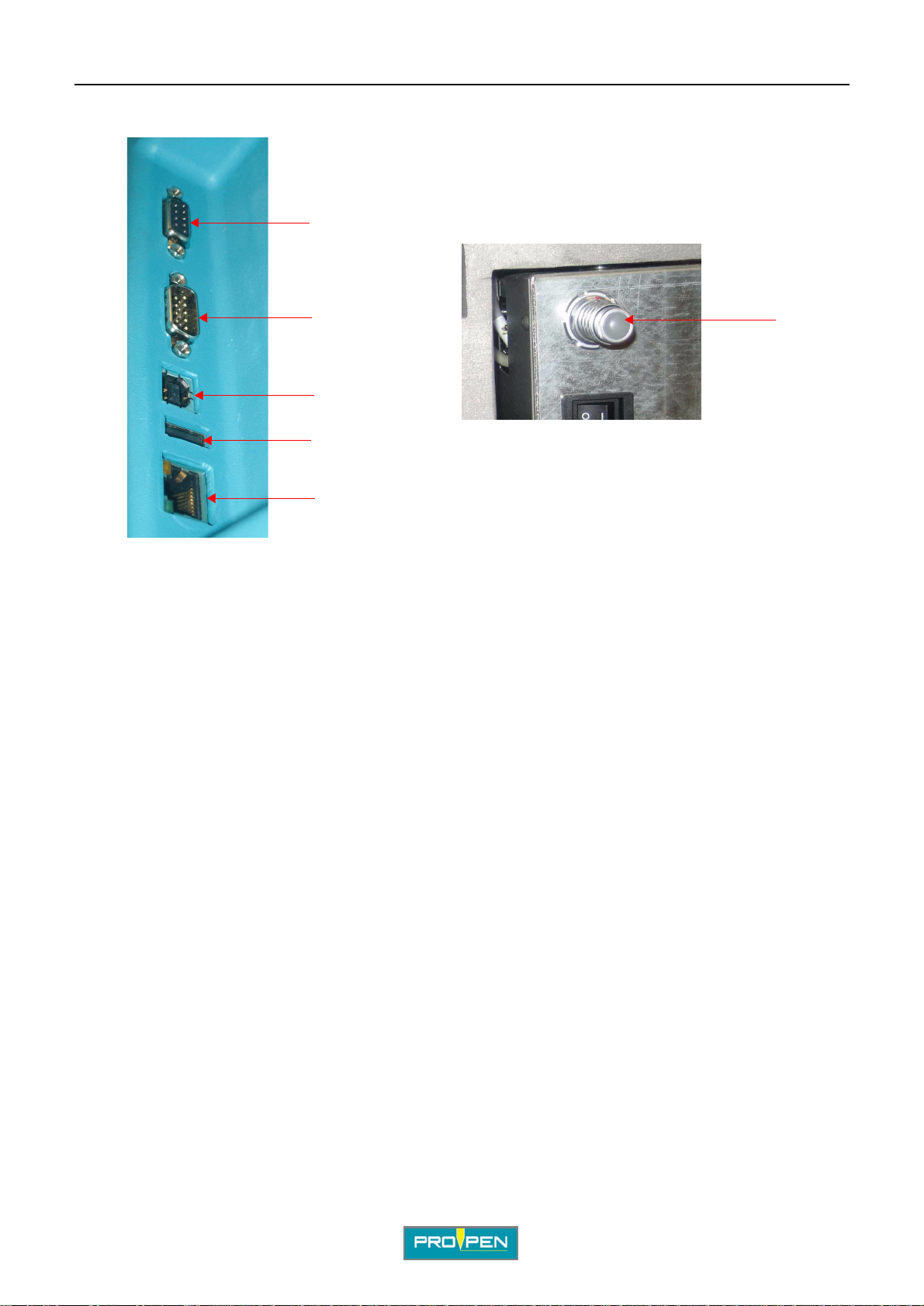
3. Connections for acces sories
1
C
2
6
3
4
5
1 : Accessory connection (st art cycle/emergency sto p button box or sta rt cycle foot pedal...) Or 1 br idged male SubD9 con nector ,
for the reset function
2 : RS232 connection for communication with PC
3 : USB_B connection DEVICE (PC link)
4 : USB_A connection HOST (marking file on key)
5 : Ethernet connection
6 : Connection for circular marking device (remove the plug from the machine)
Ref. 92198 - P5000 EM_en_C
17/34

DInstallation
1. Installation
Unpack the machine and install it at the work station.
The machine must be inst alled in a works p ace allo wing the operator easy acces s t o the adj ustment han dle for the
Z-axis and clear visibilit y of the marking area where the stylus is moving. The marking area must be easily
accessible.
It is possible to counter-sink the table of the machine into the work table in order to
prevent it tipping if too much force is applied to the vert ical adjustment handle. See
the table drawings for the dimension of the requi red rectangular cut-out.
2. Connect io ns
Safety precautions
The different elements of the equipme nt must be connecte d with the power off. The
power supply should be connected last.
D
View of connectors
To start up the machine, 4 connections are necessary:
1
2
1
3
4
1 : 1 bridged male SubD9 connector, for the reset function
2 : Compressed air (in the event of the stylus cooling by compressed air)
3 : Keyboard
4 : Power supply
Ref. 92198 - P5000 EM_en_C
18/34

AInstallation
Keyboard connection
Connect the keyboard connector socket to the machine.
There is a female connector, type DIN, on the electronics board.
Compressed air connection (in the event of the stylus cooling by compressed air)
The ideal air pressure is 4 Bar (58.015 PSI) - 6 Bar (87.023 PSI).
Foresee an air inlet pipe, 6 mm (0.236 in) diameter for the pneumatic cooling of the stylus (instant connector).
• The compressed air system must meet all standards.
D
Power supply connection
This machine comes equipped with an SMPS (switch mode power supply). No power supp ly vol tage adjustment
is necessary.
However, if the machine doesn’t start (screen off, power supply vent il ator not running...):
• Check that the power cord is correctly plugged in to both the machine and the power supply.
• Check that the switch is in the "I" position (On).
• Check the condition of the fuse.
- Unplug the power supply cord. Put the On/Off switch in the "O" (Off) position.
- Remove the fuse carrier (1) located below the power filter.
- If necessary, replace the fuse (2) with a new one (4 A TT) and plug the machine back in.
1
2
1 : Fuse carrier
2 : Fuse
Ref. 92198 - P5000 EM_en_C
19/34

AInstallation
Grounding connection
The marking equipment must be grounded in order to provide:
- a safety feature for personnel
- a set electrical potential which serves as a reference
- a means of protection against radiated parasites
High quality grounding is necessary on-site. If thi s is not the case, put in place
grounding specifically for the equipment.
3. Coordinate system
The coordinate system used in our machines is shown in the following diagram.
1 : Axis origin
2 : X axis
3 : Y axis
4 : Z axis
5 : Column
6 : Marking zone
D
• X axis: horizontal axi s going from left to right
• Y axis: horizontal axis going from the column to the operator
• Z axis: vertical axi s
When a marking cycle is launched, the stylus al ways begins at t he origin point and retu rns to the origin at the end
of the cycle.
The coordinates are given as an absolute val ue in rel ation to this point.
The Z axis is the v ertical position. Thi s axis is used to manually adjust the height of the stylu s for marking parts of
different sizes.
A vertical positioning indi cator can be found on the right side of the machine.
Ref. 92198 - P5000 EM_en_C
20/34

AInstallation
4. Hold the part to be marked
Situation 1
Used with Pro-Pen plate-holder (optional)
To mark plates or small par ts with a thickness of less than 2 mm (0.079 in), use the pl ate holder to position the
parts and prevent them from vibr ati ng when the stylus taps.
Situation 2
No plate-holder used.
To mark small or large parts, create the necessar y tool ing to position and clamp the part s un der the machine. If
the part is flexible, thi s tool ing must provide firm support under the p art to be marked. It must be held on the
worktable using the three T grooves . The position of the marking zone with relation to the T groov es is i ndicated
on the dimensional drawing of the worktable.
A poorly clamped piece c an g enerate high sound l evels, t hus becom ing har mful after long periods.
D
5. Adjusting the height of the stylus
Determining the optimum operating di stance of the stylus according to th e part to be marked.
This distance is between 1 mm (0.039 in) and 5 mm (0.197 in).
Using feeler gauges, position t he point of the stylus 4 mm (0.157 in) above the part to be marked.
Execute a marking.
The whole marking line should be legible.
Depending on the results, increase or decrease the distance between the stylus and the marking surface.
• If a stylus is set too high, it doesn’t mark because the poi nt doesn’t touch the plate
consistently while traci ng the characters.
• If the stylus is set too low, it doesn’t mark because it cannot vibr ate. The point withdraws
inside the stylus and remains in permanent contact with the plate.
Ref. 92198 - P5000 EM_en_C
21/34

AInstallation
6. Definition of operating di stances of a stylus
D
Max. distance
DM
Min. distance
Dm
Amplitude
A
Reference distance
Do
The max. distance ( DM) and min. dist ance (Dm) may va ry slightly from o ne stylus to another (pro duction
tolerances for stylus components, pressure and compressed air flow through the system).
Maximum adjustment distance
Carry out a series of markings while progressively lowering the head until a
uniform marking is obtai ned. With the help of feeler gauges, measure the
distance between the point of the st ylus at rest and the marked surface. Make a
note of this distance.
Minimum adjustment distance
Lower the head until the stylus i s barely touching the part to be marked. Raise
the head and set the distance from the point of the stylus to the surface to be
marked at Do (optimal distance), betwee n 0.5 mm (0.02 in) and 1 mm (0.039 in).
Amplitude of a stylus
Subtract the min. dist ance (Dm) from the max. distance (DM) to obtain the
operating amplitu de of the st ylus. This distance corr esponds to its operating
range, or its capacity to absorb variations in flatness.
Optimum adjustment distance
Take the average of the DM and Dm. Position the stylus at this distance (Do).
To mark curved parts using the maximum amplitude (A), set the styl us at the minimum distance (Dm)
above the highest point of the part .
7. Using the P05 program
Refer to the user manual for the P05 program.
Ref. 92198 - P5000 EM_en_C
22/34
EMarking depth
1. Factors influencing marking depth
The principle factors are:
• choosing the stylus
• distance between the stylus and the part
• marking force
• choosing the marking speed
To avoid creating stress on fragile part s, choose the following marking parameters:
• stylus EM1/C is the preferable choice.
• choose a point with the largest possib le radius.
• select marking force 25% for the marking file.
For very fragile parts, validate marking with mechanical resistance tests.
E
Choosing the stylus
The points come sharpened to a r adius of 0.2 mm (0.00 8 in). Depen ding on the nee d, points can be shar pened to
different radii ranging from 0.1 mm (0.004 in) to 0.5 mm (0.02 in).
The force varies according to the diameter of the tip of the point.
A EM1/C stylus with a point radius sharpened to 0.2 mm (0.008 in) comes standard with the machine. This point
is suitable for most common marking needs.
Ref. 92198 - P5000 EM_en_C
23/34

Stylus EM1/C
AMarking depth
E
1 : X Carriage
2 : Cooling kit for cooled version
3 : Protection tube
4 : Sensor option of the motorized Z-axis
5 : Coil
6 : Stylus nose
7 : Point
8 : Stylus fixture screw
9 : Electrical cable output
10 : Compressed air supply (in the event of the stylus cooling by compressed air)
Distance between the stylus and the part
The optimum distance (Do) of the stylus in relation to the surface to be marked decreas es as the marking force
decreases.
Using a stylus which is positioned too low, or which is too powerful i n rel ati on to the
hardness of the material, will result in distorted characters.
If the stylus is set too high, the marking will be lighter but there will be portions of the
characters marked which will be missing. In this case, choose a less powerful stylus .
The max. distance (DM) and min. distance (Dm) may vary slightly from one stylus to another (production
tolerances for stylus components, pressure and comp ressed air flow through the system). To mark curved parts
using the maximum amplitude (A), set the stylus at the minimum dist ance (Dm) above the highest point of the
part.
Ref. 92198 - P5000 EM_en_C
24/34

AMarking depth
Marking force
The width and depth of the marked line varies with the defined value.
The higher the force, the deeper the mark. This value is expressed as a percent.
Choosing the marking speed
There are 10 speeds:
The choice of speeds influences the marking quality.
Marking speed Result Speed Marking cycle
1 to 3 Very high quality Slow Long
4 to 7 High quality Fast Standard
8 to 10 Average quality Very fast Short
2. Marking depth
E
A metallographic test i s perf ormed t o measure mar king dep th. This pr ocess i s use d to di ssuade att empts to falsify
the marking.
P1 = depth of marking
P2 = depth of penetration
P3 = depth of warping
1 : Solid material
2 : Thin sheet metal
3 : Embossing
Ref. 92198 - P5000 EM_en_C
Different definitions concerning marking depth
25/34

FPreventive maintenance
The maintenance operations listed here are intended as a guideline, and should be implemented upon reception
of the material. In a highly polluted environment, these operations may need to be performed more frequent ly.
Unplug the power supply plug before beginning any cleaning or maintenance operation.
This maintenance list was established based on a marking frequency of:
• 520 000 cycles per year (7 800 000 characters per year)
• 15 characters 3 mm (0.118 in) high per cycle
2
• 8 continuous working hours on steel strength 50 DaN/mm
(72518.869 lb/in2)
1. Every week
• Clean the guide bars inside the marking head with a dry cloth (no solvent, oil, or grease).
• To have access to the point, manually unscrew the stylus nose. Remove the point.
• Check the condition of the styl us, then clean it thoroughly.
• Clean the point with a dry cloth.
1
F
1 : X carriage guide bars
2 : Y carriage guide bars
3 : Stylus nose
2. Every three months
• Have the stylus serviced by Pro-Pen. Check the belt tension.
2
3
Ref. 92198 - P5000 EM_en_C
26/34

APreventive maintenance
3. Every two years
Have the marking head serviced by Pro-Pen.
This operation includes:
• complete dismantling of the machine
• cleaning of the mechanical elements
• standard replacement of X and Y carriages
• replacement of the guide bars and belts
• verification of the condition of X and Y motors and belts
• reassembly and adjustment of mechanic al el ements
• debugging of the head in an enclosure
• marking tests
F
Ref. 92198 - P5000 EM_en_C
27/34

GGeneral maintenance
1. General information
Maintenance consists of regul ar monitoring of marking quality. Intensive use of the equipment can impact the
guiding systems of the carriage or the styl us point, and may result in distortion of th e characters.
Contact your distributor to schedule an appointment for servicing. This "tune-up" does not take a long time.
Check the compressed air system regularly. Based on the level of soiling, establish a schedule for cleaning or
replacement.
Never lubricate any part of the stylus or carriage guide bars.
• Never lubricate any element s of the stylus.
• Never use pliers to tighten the styl us.
• Never lubricate any element of the marking head.
Unplug the power supply plug before beginning any cleaning or maintenance operation.
G
2. Detaching the point of the stylus for sharpening
The tip of the point is made from a grade of carbide suitable for creati ng impacts. The point should be rounded in
order to hold up well on hard material.
To have access to the point , manual ly unscrew the stylus nose.
Ref. 92198 - P5000 EM_en_C
28/34

AGeneral maintenance
3. Changing the fuse
Disassemble the power filter located on the side of the machine.
Use a screwdriver to change the fuse. Remove the fuse from its housing and replace it with the new one.
Choosing the fuse
Delay fuse Nominal voltage Frequency
4 A TT 250 V AC 50 - 60 Hz
1
1 : Fuse carrier
2 : Fuse
G
2
4. Cleaning the sensors
The machine is equipped with 2 optoelect ron ic fork senso rs which det ect the end of trav el in X and Y and indi cate
the presence of the 2 car ri ages at the origin. Certain exteri or elements (chips, shavings...) can get stuck between
the sensors and disrupt their functi oning: the setting of the origin will not be accurate. To remove these foreign
objects, use an air blower to direct a blast of air between the sensors.
1
2
1 : Y Sensor
2 : X Sensor
Ref. 92198 - P5000 EM_en_C
29/34

HResolution of the problems
1. Possible marking problems and problem resolution
Situation Description Diagnosis Action
H
1 The stylus is not vibrating
sufficiently and the part is not
marked.
2 The point of the stylus doesn’t
mark the part.
3 Intermittent characters The point of the stylus was oil ed
4 Only the upper, or lower, par t of
the characters is marked.
5 Only the left, or ri gh t, p ar t of the
characters is marked.
The stylus is too close to the
surface to be marked.
The stylus is too far from the
surface to be marked.
or lubricated.
The part doesn’t have a
constant thickness in the Y
direction.
The part doesn’t have a
constant thickness in the X
direction.
Raise the marking head, then try
marking again.
Lower the marking head, then try
marking again.
Dismantle the stylus.
Remove the point.
Clean the point with a dry cloth.
Reassemble the stylus.
Use feeler gauges to reposition the
part so that it is level.
Use feeler gauges to reposition the
part so that it is level.
Ref. 92198 - P5000 EM_en_C
30/34

AResolution of the problems
2. What to do if...
Situation Description Things to check Action
H
1 The screen on the front of the
machine is blank.
2 One of the carriages, X or Y,
does not return to the origin
when the start marking
command is given.
3 Lost in the program? Refer to the manual. Press Esc and answer "no" to the
4 Marking doesn’t start. / No
access to the "Marking" menu
5 Irregular marking The CAN plug is not connected. Connect the CAN plug.
Is the power supply switched
on?
Is the cable properly
connected?
Is the On/Off switch in the On
position?
Is the fuse on the back of the
machine in good condition?
• The sensors are dirty.
• The machine’s mecha nics are
obstructed.
The bridged male Sub-D9 connector or on one of the accessories is not connected.
See: Power supply connection
See: Changing the fuse
• Clean the sensor by directing a
blast of air inside the fork with an air
gun.
• Turn off the machine and move
both carriages until the stylus is in
the middle of its travel. Try to
execute another marking.
questions from the program until
you’re back to the main menu.
Connect the Sub-D9 bridged connector or the accessory.
Ref. 92198 - P5000 EM_en_C
31/34

IWearing and spare parts
Please give the item codes with your order to speed processing.
1. Spare parts
These parts may present a risk for breakdown under normal operating conditions of the machine. Mechanical
parts are excluded since in theory they are not considered a potential cause for breakdown.
Reference Description
92067 LCD screen
I
2757 (USA), 2755
(UK)
2742 Head casing with decals
3157 Column casing with decals
90020 Z axis crank handle
4020 Aluminum work table
90012 Rubber pads (4)
Keyboard and functions strip
2. Consumables
Reference Description
2685 Points for EM1/C stylus
2688 Repair kit stylus EM1/C (seal + spring + washer)
4225 Fuse 4 A TT
Ref. 92198 - P5000 EM_en_C
32/34

JNoise emission of the machine
1. Test code
Measurement method
The measurements were taken according to the regulations of standard NF EN ISO 11201:1996.
Measurement equipment used:
• 01dB - Stell int egrated sonometer, SI P 95 S, # 20394
• cal 01 calibrator, # 40141
Material used for marking:
• type P5000 EM machine mounted on a column stand
The unit is placed on a wood workbench in a workshop where t he background noise level is negligible compared
with the noise emitted by the machine. The work station, situated more than 2 m (6.562 ft) f rom any separator, is
designed for a standing operator.
The marking is carried out usi ng a EM1/C stylus on a steel plate with di men sions of 110 mm (4.331 in) x 100 mm
(3.937 in) x 3 mm (0.118 in) clamped to a base support. A new plate is used for each test .
J
Definition of the microphone position
The microphone is positioned 1 m (3.281 ft) in fro nt of the machine and 1.6 m (5.249 ft) from the floor.
Test conditions
• marking speed: 100%
• stroke force: 50%
• marking of 3 lines of 18 characters 5 mm (0.197 in) high
• steel plate with dimensions 110 mm (4.331 in) x 100 mm (3.937 in) x 3 mm (0.118 in)
2. Nois e emiss ion information
The values given bel ow represent the noise emitted by the machine during marking. When the machine is in us e,
the values mentioned ar e i ndependent from t he tot al noi se le vel t o which th e operat or is ex posed, s ince t he a ctual
noise level will vary depending on the operator’s environment.
• average le v e l: L
(L
= "equivalent" average sound level mea sured using the A-weighting)
Aeq
• peak level: Lpc < 108 dB(C)
= 76 dB(A)
Aeq
= peak acoustic pressure level)
(L
pc
When marking resonant parts (metallic, hollow, thin), wear hearing protection for
sound levels L
Ref. 92198 - P5000 EM_en_C
> 85 dB(A) or Lpc > 137 dB(C).
Aeq
33/34

To contact the GravoTech Group
KAppendix
K
www.pro-pen.com
GravoTech Marking SAS
114, quai du Rh
01708 MIRIBEL Cedex Tel.: 33 (0)4 78 55 85 63 Fax: 33 (0)4 78 55 85 66
E-mail: dvfr@pro-pen.com
ENGLAND
Gravograph UK Ltd
Unit 3 Tro jan Business Cent re
Tachbrook Pa r k Esta te
LEAMINGTON SPA
CV34V 6RH Warwickshire
Tel. : (44) 19 26 88 44 11
Fax : (44) 19 26 88 31 05
E-mail: sales-uk@pro-pen.com
SPAIN
Technifor Marc adores Industriales SL
C/ Sant Iscle, 29 bajos B
08031 BARCELON A Tel. : (34) 93 407 07 51 Fax : (34) 93 407 17 26
E-mail: spain@pro-pen.com
BENELUX
Gravograph Benelux
Molenberglei 28
2627 SCHELLE Tel. : (32) 3 88 0 6200 Fax : (32) 3 888 1997
E-mail: info@gravograph.be
FRANCE
ô
ne
GERMANY
GravoTech GmbH
Am Gansacker 3a
79224 UMKIRCH
Tel. : (49) 76 65 / 50 07-0
Fax : (49) 76 65 / 61 36
E-mail: germany@pro-pen.com
AUSTRIA
GravoTech GmbH
Porschestra
3106 ST PÖLTEN
Tel. : (43) 27 42 72 87 70
Fax : (43) 27 42 76 863
SWEDEN
GravoTech Nordrad AB
Vretenborgsv
SE-126 30 H
Tel. : (46) 8 658 15 60
Fax : (46) 8 658 15 64
E-mail: info@gravotech.se
ß
ä
gen, 28
Ä
GERSTEN
U.S.A.
Technifor Inc.
9800-J Southern Pine Boulevard
CHARLOTTE, NC 28273
Tel.: (1) 704 52 5 5230
Fax: (1) 704 525 5240
E-mail: usa-sales@pro-pen.com
e
E-mail: sales@gr avograph.com.ch
Ul. Gen. Grota Roweckiego 168
ITALY
GravoTech Italia Srl
Via Rivera, 13 8
10040 ALMESE (TO) Tel. : (39) 011 935 27 14 Fax : (39) 011 934 59 42
E-mail: info@technifor .it
SWITZERLAND
Gravograph Switzerland
Champ Olivier 2
Ch 3280 MORAT
Tel. : (41) 26 678 7200
Fax : (41) 26 678 7222
POLAND
GravoTech Sp zoo
PL 52-214 WROCLAW
Tel. : (48) 71 796 04 01
Fax : (48) 71 796 04 02
E-mail: infopl @pro-pen.com
CHINA
GravoTech Engraving Equipment Co. Ltd
N. 3388 Humin Road, Minhang District
SHANGHAI 201108
Tel. : (86) 21 / 51 59 18 28
Fax : (86) 21 / 51 59 18 23
E-mail: sales-c n@cn.gravotech.com
SINGAPORE
Gravograph Si ngapore Pte Ltd
#06-09 8 @ Tradehub 21
8 Boon Lay Way 609964 SINGAPORE Tel. : ((65) 6316 1512 Fax : (65) 6316 1513
E-mail: sales@gravograph.com.sg
AUSTRALIA
Gravograph Aus tralia
Unit 3, 7-11 South Street
RYDALMERE N.S.W. 2116
Tel. : (61) 29 684 2400
Fax : (61) 29 684 2500
E-mail: sales@gr avograph.com.au
MALAYSIA
GravoTech Sdn Bhd
No. 29, Jalan Puteri 5/10
Bandar Puteri
47100 PUCHONG, SELANGOR
Tel. : (60) 3 80 685512 & 80 683512
Fax : (60) 3 80 61251 3
E-mail: sales@grav ograph.com.my
INDIA
GravoTech Engineering PVT Ltd
Gat No 2323/1, "Reality Warehousing"
Nagar Road
PUNE WAGHOLI 412 207
Tel. : (91) 20 / 41030000
Fax : (91) 20 / 41030010
E-mail: gravot ech@vsnl.net
MEXICO
GravoTech S. DE R.L DE C.V
Av. 16 de Septiemb re # 46 Int Q y 20
Fracc. Alce Bl anco
Naucalpan, Estado de México
C.P. 53370 MEXICO
Tel. : (52) 55 5357-2766 / 67
Fax : (52) 55 5357-2765
E-mail: npari zon@gravogra ph-newhe rmes.com
JAPAN
GravoTech KK
1-25 Takahata-Cho
NISHINOMIYA-SHI
HYOGO 663-8202
Tel. : (81) 798 63 7325
Fax : (81) 798 63 6280
E-mail: sales-jp@pro-pen.com
TURKEY
GravoTech STI Turkey
Atiye Hanım Sokak No. 13
34752
İ
ÇERENKÖY / İSTANBUL
Tel: (90) 216 577 64 54
Fax: (90) 216 574 56 02
E-mail: info@tr.gravot ech.com
BRAZIL
Technifor Pictor Ltda
Av. Dr. Luis Arrobas Mar tins, 98
04781-000 - SAO PAULO SP
Tel. : (55) 11 5541 74 93
Fax : (55) 11 5541 74 93
E-mail: brasil @pro-pen.com
Ref. 92198 - P5000 EM_en_C
34/34
 Loading...