


www.pro-pen.com
TECHNICAL AND OPERATING MANUAL
M3000/d
PNEUMATIC VERSION
Reference : 90703-MDIS-4314/0810C1
Distributor stamp
P R O - P E N
Propen reserved all rights on improvement of its products.
This document is not contractual.

PRO-PEN (Ref.90703-MDIS4314/0601C0-chap014314.fm.doc)
- 2

(Ref.90703-MDIS4314/0601C0-chap014314.fm.doc) PRO-PEN
Foreword
Before reading this manual, it is recommended, unless you have already done so, that you view the start-up video
included on the CD-ROM and execute the provided marking exercise .
It is nevertheless also highly recommended that you read the entire manual.
This machine is designed for marking applications. The manufacturer is not responsible for the quality of the work, or
for any damage resulting from improper use of the M3000, should it be used for any purpose other than marking.
This manual is designed to help you find the information you need as quickly and efficiently as possible.
It is made up of five main sections :
• Introduction - Start up,
• Using the marking program with a PC keyboard in the "program" mode,
• Using the marking program with a mini-keyboard in the "marking" mode,
• Using the machine,
• Technical data about the machine.
An index of key words will help you find information.
Furthermore, the four icons displayed below will help you to pinpoint the important points in the manual :
SAFETY AT THE WORKSTATION
Indicates the various precautions to be taken before installing and using
the M3000 safely.
RECOMMENDATIONS AND LIMITS OF WARRANTY
Indicates the various procedures to be followed to conform to the conditions of
the warranty.
ADVICE ON USE
Further advice on optimizing the performance of your M3000.
WHAT TO DO IF........
This icon refers to a chart in the last chapter giving instructions on what to do in
case of problems or a malfunction of your marking equipment.
- 3

PRO-PEN (Ref.90703-MDIS4314/0810C1-chap014314.fm.doc)
Technical Manual Updates
This chart will help you to keep track of the various updates to the manual since the first edition.
Date of
Revision
November 2003 0311A0 First edition
November 2003 0311B0 - Development of program P03 : version V6.00
January 2006 0601C0 . Change in certifying organization,
October 2008
Revised
name
0810C1
Modified pages
- Assembly with C clips
. Update of conformity certificate:
- Directive 98/37/CE,
- Directive 2002/96/CE.
Update of Regulation observance
- 4

(Ref.90703-MDIS4314/0601C0-chap014314.fm.doc) PRO-PEN
1
INTRODUCTION
AND START-UP
INTRODUCTION AND START-UP 1 - 5

PRO-PEN (Ref.90703-MDIS4314/0601C0-chap014314.fm.doc)
1 - 6 INTRODUCTION AND START-UP

(Ref.90703-MDIS4314/0601C0-chap014314.fm.doc) PRO-PEN
1.1) Unpacking Instructions
When opened, the package will appear as shown below:
power block
battery pack
lateral handle
accessories
documentation
battery cable
PC keyboard
INTRODUCTION AND START-UP 1 - 7

PRO-PEN (Ref.90703-MDIS4314/0601C0-chap014314.fm.doc)
1.2) Description of the M3000
1.2.1. Generalities
The M3000 is a numerically-controlled micro-percussion marking M3000. The mechanical part is based on a X/Y table
guided by step by step motors that move a marking tool.
The electronic command is incorporated within the machine. It is made up of electronic boards and a cooling system.
The man/M3000 interface is also incorporated and made up of :
1 LCD screen
1 Mini keyboard
1 switch on the handle to trigger marking.
All of the elements making up this equipment are run by a simple user-friendly marking program.
The external PC keyboard (105 keys) is also included with the M3000 for easy programming of the files.
As a further option, the M3000 may be driven by a Windows® based program when connecting the Control Unit to a PC
using an RS232 cable.
Its light weight and its specially conceived ergonomics will permit the operator to carry it to the parts to be marked no
matter where they are located, on a working site, in a hangar, etc...
The electric power needed to run the M3000 may come directly from the mains supply or from the portable battery attached to the operator’s belt.
The connection to the pneumatic supply is situated at the end of the handle.
1 - 8 INTRODUCTION AND START-UP

(Ref.90703-MDIS4314/0601C0-chap014314.fm.doc) PRO-PEN
1.3) Physical Characteristics
• Weight : 4.8 Kg. - side handle excluded
• Layout of overall dimensions
DIMENSIONS
Unit
INTRODUCTION AND START-UP 1 - 9

PRO-PEN (Ref.90703-MDIS4314/0601C0-chap014314.fm.doc)
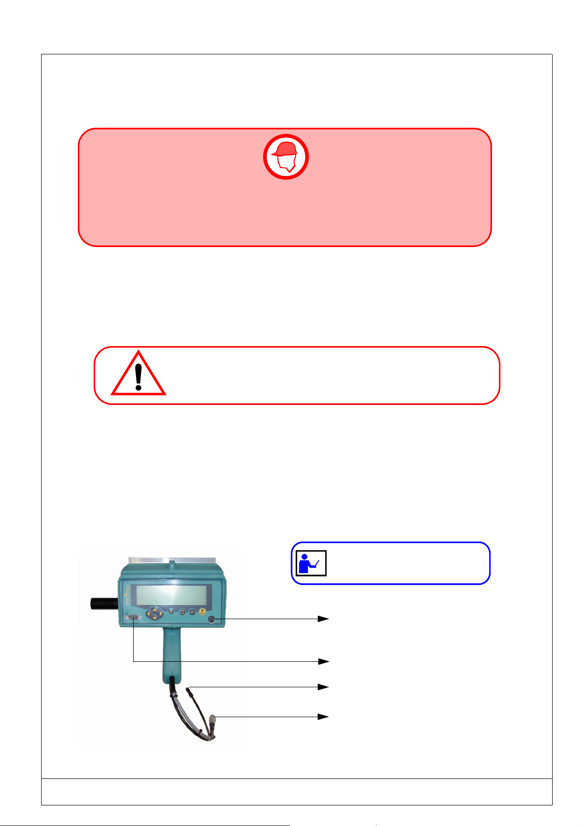
1.4) Functional description
Hole for lifting ring
front side
RS232 plug for connection
with a PC
Lateral support handle:
It can be attached on the right
or on the left of the M3000.
Power Outlet towards:
- the mains supply
or
- the battery
mini-keyboard
keyboard plug outlet
of PC type
1 - 10 INTRODUCTION AND START-UP

(Ref.90703-MDIS4314/0810C1-chap014314.fm.doc) PRO-PEN
1.5) Identification plate of the marking equipment
Your marking equipment may be identified by its descriptive plate glued on the M3000.
Please note down the type and the serial number of the element for all correspondence with Pro-Pen.
INTRODUCTION AND START-UP
1 - 11

Regulation observance
Manufacturer, GravoTech Marking SAS - 56 avenue Jean Jaurès BP 80015 - 10604 LA CHAPELLE SAINT LUC France (head office) declares:
! Declaration of compliance
CE marking on the equipment attests the observance of the following European directives:
• Directive 98/37/EC of the European Parliament and of the Council of 22 June 1998, concerning the consolidation of the laws of member states relating to the machines.
• Directive 2006/95/EC of the European Parliament and of the Council of 12 December 2006 on the harmonisation of the laws of the Member States relating to electrical equipment designed for use within certain voltage
limits.
• Directive 2004/108/EC of the European Parliament and of the Council of 15 December 2004 on the harmonisation of the laws of the Member States relating to electromagnetic compatibility.
! Declaration of compliance to other directives
Equipment is compliant with the following European directives:
• amended Directive 2002/96/EC of the European Parliament and of the Council of 27 January 2003 on waste
electrical and electronic equipment (WEEE).
Waste Electronic and Electrical Equipment
This symbol indicates that once this equipment has reached the end of its useful life, it must not be
disposed of with non-sorted municipal waste, in accordance with European Directive 2002/96/EC.
The equipment must be disposed of at an appropriate collection point for processing, sorting, and
recycling of Waste Electronic and Electrical Equipment (WEEE).
The elements which compose Waste Electronic and Electrical Equipment (WEEE) may contain substances which
have harmful effects on the environment or on human health.
By following these instructions, you are helping the environment, contributing to the preservation of our natural
resources, and protecting human health.
! Declaration of compliance to norms
The equipment is compliant with the following norms:
• Standard NF EN 61000-6-2 of January 2006 concerning electromagnetic compatibility (EMC) - Part 6-2: generic
standards- Immunity for industrial environments.
• Standard NF EN 61000-6-4 of March 2007 concerning electromagnetic compatibility (EMC) - Part 6-4: generic
standards- Standard on emissions for industrial environments.
The modification or transformation of this equipment, adaptation and accessor y
installation unrecommended by Pro-Pen modify this equipment’ s characteristics and
therefore void the compliance with the applicable EU directives. These modifications
void Pro-Pen’s liability. In this case, the machine and equipment installer is
responsible for the final work station’s compliance.

PRO-PEN (Ref.90703-MDIS4314/0810C1-chap014314.fm.doc)
1.7) Limits of use and recommendations
To ensure your safety and extend the life of your M3000, please read this manual before using the
equipment.
• This equipment has been designed to function between :
• 5°C and 40°C with mains power,
• 5°C and 30°C with battery supplied power.
• Do not use this marking equipment in an explosive environment.
• The ground connection of the M3000 must conform to current legislation. The M3000 should be
connected to the electric monophased power supply using a standard 3 pin plug including one
ground connection.
• During marking operations, the operator should keep fingers and all other objects away from the
area where the marking tool will evolve.
Should this advice be disregarded, possible injuries could result in pinching and light scratching.
1.8) Conditions of warranty and limits of use
This equipment is designed to be used with PRO-PEN marking tools. Any other use, or the use of a non
PRO-PEN marking tool is the sole responsibility of the operator.
• Never lubricate any part of the marking tool or the guiding bars of
the carriages with any product whatsoever.
• Never use more than 6 Bar of air pressure.
• The compressed air has to be brought in by a suitable installation.
• The air has to be clean and dry and not greasy.
PRO-PEN is not responsible for any injuries resulting from disregard of the above rules of operation,
or other general safety rules applicable for the use of this equipment. Furthermore, disregard of this
advice may suspend the warranty.
For more information, please refer to the warranty note delivered with the M3000.
• The batteries are not included in the warranty of your M3000. In order to lengthen their
lifespan, consult the recommendations found in chapter 4.3) Battery and Charger
• Never use any battery or power supply not delivered by PRO-PEN
• Never recharge the battery with a charger other than the one delivered by PRO-PEN.
1 - 12
INTRODUCTION AND START-UP
(Ref.90703-MDIS4314/0601C0-chap014314.fm.doc) PRO-PEN
1.9) Start - up
MAKE SURE THAT THE M3000 IS SWITCHED OFF BEFORE MAKING ANY ELECTRICAL
CONNECTIONS OR CONNECTING COMPONENTS.
THE POWER SUPPLY SHOULD BE CONNECTED LAST.
1.9.1. Installation
After unpacking the equipment, it should be installed on a workbench.
• Never place the M3000 on the floor.
Liquid or solid impurities could seep into the M3000 and block its running.
1.9.2. View of the connections
To start the M3000, connect it to 24V power, then, depending on the case, connect it to either:
• the PC keyboard
or
• the RS232 connection
The RS232 connection is not obligatory for operating
keyboard connection
RS232 connection
Connection for pipe Ø4 x 6
Power 24V connection
INTRODUCTION AND START-UP 1 - 13

PRO-PEN (Ref.90703-MDIS4314/0601C0-chap014314.fm.doc)
1.9.3. Connecting the keyboard
Plug the connecting plug to the socket shown in the picture on page 12.
The connector of the M3000 is a Mini Din female type.
1.9.4. Connecting the compressed air
A rapid connector for flexible tubing (.Ø 4 x 6) is fitted at the end of the tubing. If your installation uses tubing of a
different diameter, this connector can be replaced by one of an appropriate diameter
The air pressure at the connector should always be between 5.5 and 6 Bar.
The usage of tubing that is too long will cause a drop in pressure. In this case, the pressure at the end where the air enters
should be above 6 Bar in order to ensure a range of 5.5 to 6 Bar at the gun entrance.
Use a pressure reducer valve/ pressure release valve with a simple filter (Ref.: 2501).
1.9.5. Connecting the power supply
1.9.5.1 - Connecting the power supply
• Check that the input voltage of your power supply is correct: 115 or 230V
The power supply must be connected in this order:
1. M3000 : Attach and lock the metallic male connector to the female connector.
2. Supply : Reconnect the male plug to your low voltage power supply.
1.9.5.2 - Connecting the battery (optional)
• Put on the battery belt. The battery should be on your back.
• From the M3000 side :
- Push and screw the metallic male connector to the 1 m. cable (female part)
- Push and screw the circular plug (Jack type, 6.35mm) to the rear of the battery case
1.9.6. Connection to a ground connection in both cases:
The marking equipment must be properly grounded to provide:
- A safe environment for the operators,
- A permanent electric potential to be used as a reference,
- A protection against electromagnetic interference.
The ground connection in the factory must be of good quality. If such were not the
case, a specific ground connection should be installed for the marking equipment.
1 - 14 INTRODUCTION AND START-UP

(Ref.90703-MDIS4314/0601C0-chap014314.fm.doc) PRO-PEN
INTRODUCTION AND START-UP 1 - 15

PRO-PEN (Ref.90703-MDIS4314/0601C0-chap014314.fm.doc)
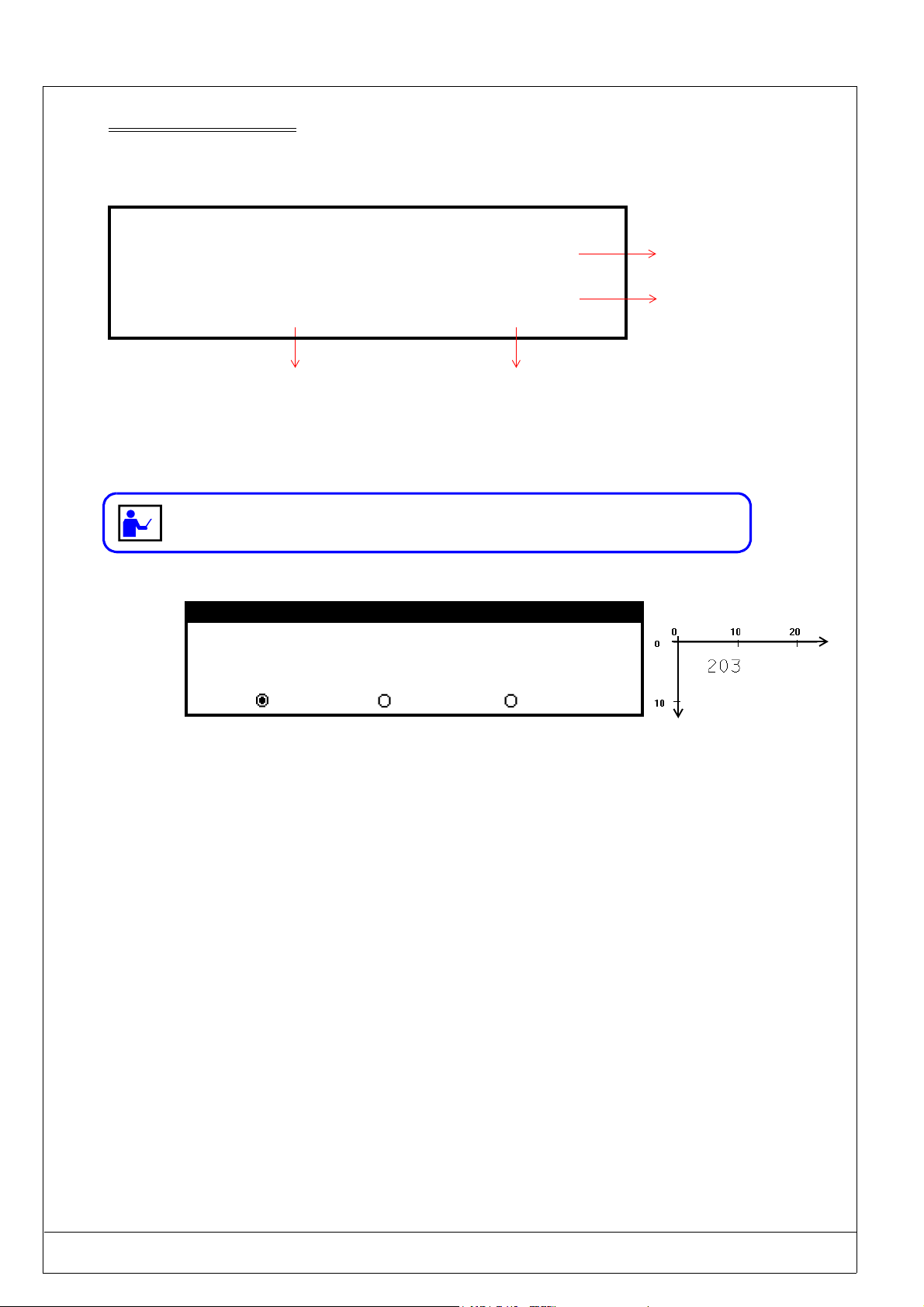
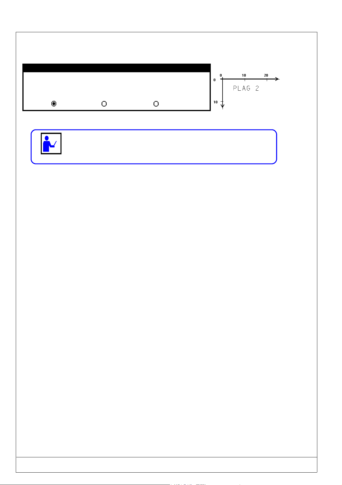
1.10) Coordinate system
The coordinate system used by your M3000 is as shown in this diagram.
The origin position in relation to the foot is given with a ± 1.5mm. tolerance. This
position is defined by the 3 and 5mm values.
.
Y axis - 40mm path
Origin
Foot
X axis - 60mm path
COORDINATES
Unit
When you hold the M3000 :
• The coordinates will be given in absolute values in relation to the origin.
• The X axis is a horizontal axis going from left to right.
• The Y axis is a downward vertical axis.
The two axes are run by the marking program.
At the beginning of a cycle, the marking tool will always begin at the 0 origin and will return to this origin point at the
end of the cycle.
1 - 16 INTRODUCTION AND START-UP

(Ref.90703-MDIS4314/0601C0-chap014314.fm.doc) PRO-PEN
1.11) Starting up the program
The marking program will automatically start when the M3000 is switched on:
An introduction screen will appear after a few seconds:
Name
PRO PEN
and then will be replaced by the main menu screen shown in the following chapter.
Version XXXX (XX/XX/XXXX)
M 3000
program
version
(Nº + date)
Should you have any problems or questions regarding your equipment,
please contact your distributor, giving the information shown on the
introduction screen.
After turning the power on, two cases shown below could possibly occur:
Power on
PC keyboard
connected
NO
See chapter 3 - operating
with the mini keyboard
See chapter 2 - operating
with an external keyboard
YES
INTRODUCTION AND START-UP 1 - 17

PRO-PEN (Ref.90703-MDIS4314/0601C0-chap014314.fm.doc)
1 - 18 INTRODUCTION AND START-UP

(Ref.90703-MDIS4314/0601C0-chap024314.fm.doc) PRO-PEN
2
USING THE MARKING
PROGRAM WITH
EXTERNAL KEYBOARD
IN "PROGRAMMING"
MODE
USING THE MARKING PROGRAM WITH EXTERNAL KEYBOARD IN "PROGRAMMING" MODE 2 - 1

PRO-PEN (Ref.90703-MDIS4314/0601C0-chap024314.fm.doc)
2 - 2 USING THE MARKING PROGRAM WITH EXTERNAL KEYBOARD IN "PROGRAMMING" MODE

(Ref.90703-MDIS4314/0601C0-chap024314.fm.doc) PRO-PEN
2.1) General information
The following chart shows the the marking program’s many possibilities..
Marking Possibilities: Texts
Logos
CE logo in separated dots
Lines - circle - arcs of circle - ovals - rectangles
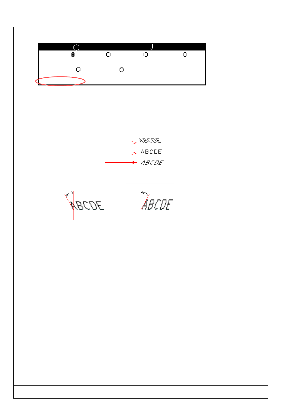
Fonts: Continuous stroke
Highly legible separated dots
5x7 standard
Marking Type: Linear, horizontal or vertical marking
Angular and radial marking
Marking date and hour
Marking variables (serial numbers, batch numbers ,
shifts...)
Marking effects: Normal
Inverted
Mirrored
Reflected
Character format: Height of characters from 1 to 80 mm (0.1mm steps)
Automatic centering of text
Compression of characters between 0.1 and 9.99
Inclination of characters between -180° and +180°
Variable spacing between characters
Software functions: Creation of marking files
Marking one time, n times, infinite and repeat last
Short cut funtion keys
Simulation of marking file or block
Pause after the blocks
Parameters Choice of user language
Conversion and management of units : millimeters or
inches
Two user levels : operator or supervisor
Downloading of logos
Definition of marking priorities (marking quality, intermediate, cycle running time)
Indication of "Julian" date and daylight saving time
Historical file
Dialogue configuration with machine
Data reception by RS232
USING THE MARKING PROGRAM WITH EXTERNAL KEYBOARD IN "PROGRAMMING" MODE 2 - 3

PRO-PEN (Ref.90703-MDIS4314/0601C0-chap024314.fm.doc)
2.2) The program menus
2.2.1. Main menu
The main menu has five sub-menus, each represented by an icon :
Marking Menu
(see chapter 2.6)
File Menu
Create/Display/Modify
marking files
(see chapter 2.6)
File Manager Menu
(see chapter 2.7)
Downloading Menu
Communication with PC
Configuration Menu
(see chapter 2.9)
H
Function Mode
(see chapter 2.9.1.)
(optional)
(see chapter 2.8)
2 - 4 USING THE MARKING PROGRAM WITH EXTERNAL KEYBOARD IN "PROGRAMMING" MODE

(Ref.90703-MDIS4314/0601C0-chap024314.fm.doc) PRO-PEN
2.3) Access to different menus
The external keyboard gives access to the various menus and functions of the marking program, and will permit you to
enter information needed for marking. The main keys used are the following :
ENTER
ESC
ARROW KEYS
UP - DOWN
LEFT
RIGHT
FUNCTION
KEYS
F2 TO F12
PAG E U P
PAGE DOWN
SPACE
TAB
F2
Esc
Access to different menus or to different entry zones in a marking file.
Validate data.
Return to the previous screen.
Move the cursor within the entry zones.
Access to different program functions.
F12
Move between blocks in a marking file.
Moving the cursor between the various entry zones.
ESC : Return to previous screen F2 to F12 : Access to different
program functions
Esc
~
!
1
Tab
Ctrl
SPACE : Activation / Deactivation
of ticked boxes
2
F1
F3
F2
2
“
£
2
3
F4
$%
5
4
F5 F6
&
6
F7
(
‘
7
)
8
9
F8
#
0
F9 F10
=
-
QWER TYU I OP
AS D F GHJ K L
MZXCVBN
Alt
+
;
^
<
>
.
,
Alt Gr
ENTER : Validation
of entered data
?
/
105 Keys AT Keyboard (QWERTY)
Access a menu using the TAB
or arrow keys.
The selected icon will be backlighted
Press
PAGE UP- PAGE DOWN :
Moving between blocks
Scroll
lock
End
Pause
Attn
num
/
lock
*
789
456
123
End
0
Inser Delete
.
_
+
Enter
Screen
F11 F12
print
Syst
_
_
{
@
[
}
]
Inser
Delete
Enter
Ctrl
ARROW KEYS UP-DOWN-LEFT-RIGHT :
Moving the cursor within
the entry zones
USING THE MARKING PROGRAM WITH EXTERNAL KEYBOARD IN "PROGRAMMING" MODE 2 - 5

PRO-PEN (Ref.90703-MDIS4314/0601C0-chap024314.fm.doc)
2.4) Definition of a marking file
A marking file contains all the data to be marked on a part. It may be made up of one or several lines.
In the language of PRO-PEN, a marking file is made up of marking blocks.
The block to be marked may be made up of alphanumeric text or a logo,...
A marking file contains between 1 and 25 marking blocks.
The marking file for the plate shown opposite is made up of
5 marking blocks.
The following pages will explain the preparation of these
marking blocks.
All the necessary details for the personalization of the marking blocks will be included. (creation or
modification of a file, etc.)
2.5) Creation of a marking file
2.5.1. New marking file:
A new marking file may be created at all times using
the SHIFT + F5 keys
F5
+= NEW FILE
2 - 6 USING THE MARKING PROGRAM WITH EXTERNAL KEYBOARD IN "PROGRAMMING" MODE

(Ref.90703-MDIS4314/0601C0-chap024314.fm.doc) PRO-PEN
2.5.2. Marking data entry screen
The following procedures must be carried out when creating the first marking file.
Select the “File” Menu using the arrow keys. Press or TAB
No files in memory. Press F5 to create a file.
F5
to validate.
H
Block :
Esc
*
X : 0.00 Y : 0.00 [mm]
Text :
Size : 0.50 [mm] Stroke : 2
Linear Angular Radial
F2
Block : 1
8 / 81
Normal Mirrored Inverted Reflected
Centering
Compression : 1.00
Pause Font N° : 0
Spacing : 1.00
Inclination : 0.00
To move between blocks in a marking file, use the "Page UP" and
"Page DOWN" keys located above the 4 arrow keys (see § 2.3)
:
4/4
:
Block : 1/1
“Empty” marking
block with
entry zones for entering
characteristics.
Esc
Special
marking
effects
Access to previous block in the marking file
Access to following block in the marking file
USING THE MARKING PROGRAM WITH EXTERNAL KEYBOARD IN "PROGRAMMING" MODE 2 - 7

PRO-PEN (Ref.90703-MDIS4314/0601C0-chap024314.fm.doc)
2.5.3. Preparing a marking block
2.5.3.1 - Marking characteristics
7
1
*
2
3
1 - X-Y Coordinates............................................................... 2.5.4. 2-9
2 - Text to be marked ............................................................. 2.5.5. 2-10
3 - Character size....................................................................2.5.6. 2-12
4 - Stroke................................................................................2.5.7. 2-12
5 - Type of marking................................................................ 2.5.8. 2-13
6 - Block N° ...........................................................................2.5.9. 2-18
7 - Number of current file ....................................................2.5.10. 2-18
2.5.3.2 - Marking parameters
X : 0.00 Y : 0.00 [mm]
Text :
Size : 0.50 [mm] Stroke : 2
Linear Angular Radial
55 5
Chapter Page
88 8
1
Block : 1/1
6
4
8
Block : 1
Normal Mirrored Inverted Reflected
2
3
Centering
Compression : 1.00
Inclination : 0.00
14
8 - Marking effect ......................................................................................2.5.11. 2-19
9 - Automatic centering ............................................................................... 2.5.12. 2-21
10 - Pause ...................................................................................... 2.5.13. 2-22
11 - Font N° ..................................................................................... 2.5.14. 2-23
12 - Compression ..................................................................................... 2.5.15. 2-23
13 - Spacing ..................................................................................... 2.5.16. 2-23
14 - Inclination ...................................................................................... 2.5.17. 2-24
8 / 81
Pause Font N° : 0
Spacing : 1.00
10
13
:
4/4
:
11
Chapter Page
2 - 8 USING THE MARKING PROGRAM WITH EXTERNAL KEYBOARD IN "PROGRAMMING" MODE

(Ref.90703-MDIS4314/0601C0-chap024314.fm.doc) PRO-PEN
MARKING CHARACTERISTICS
2.5.4. X and Y Coordinates
*
X : 2.50 Y : 10.00 [mm]
Text :
Size : 0.50 [mm] Stroke : 2
Linear Angular Radial
The X - Y coordinates position the text in the marking zone.
They are given :
- In millimeters or in inches, depending on the chosen units,
- With a precision of 0.1 mm (5/100"),
- In absolute values related to the M3000 origin.
These coordinates may be entered :
- Using the keyboard directly,
- Using the F3 function key (see chapter 2.10.2.)
- Using the F9 function key (see chapter 2.10.8.)
Y = 10 mm
X = 2.5 mm
0
10
Y
Block : 1/1
100
20
X
2.5.4.1 - Linear and angular marking
For these two modes, the coordinates correspond to the point at the bottom left of the first character
marked.
X
0
0
Y
10
Y
10
Linear marking
20
X
X
0
0
10
Y
Y
10
Angular marking
20
X
2.5.4.1 - Radial marking
The coordinates correspond to the center of a base circle.
0
10
0
10
Y
X
20
X
20
Y
USING THE MARKING PROGRAM WITH EXTERNAL KEYBOARD IN "PROGRAMMING" MODE 2 - 9
Radial marking

PRO-PEN (Ref.90703-MDIS4314/0601C0-chap024314.fm.doc)
2.5.5. Text to be marked
*
X : 0.00 Y : 0.00 [mm]
Text : Marking machine
Size : 0.50 [mm] Stroke : 2
Linear Angular Radial
Enter the text to be marked in the designated block
The text may be made up of :
and/or
upper and lower case characters,
and/or
numbers,
and/or
lines,
and/or
“keywords”
The maximum number of characters per block is 30.
The letters and numbers to be marked depend on the font selected.
(see chapter 2.9.7.).
Block : 1/1
2.5.5.1 - Definition of "keywords"
The keywords correspond to codes interpreted by the marking program.
These are not marked literally, but “converted” before marking. The keywords are framed between the character @.
2.5.5.2 - Using "keywords"
Keywords must be framed by the character "@" in the text entry zone.
Example of a marking file :
*
X : 5.00 Y : 5.00 [mm]
Text : @"Miribel, "DD/MM/YY@
Size : 3.00 [mm] Stroke : 2
Linear Angular Radial
Marking obtained
Block : 2/2
X
Miribel, 07/02/01
Y
2 - 10 USING THE MARKING PROGRAM WITH EXTERNAL KEYBOARD IN "PROGRAMMING" MODE

(Ref.90703-MDIS4314/0601C0-chap024314.fm.doc) PRO-PEN
List of "Keywords"
KEYWORDS DEFINITION CORRESPONDING MARKING
@DD@ day of the month - 01 to 31 09 - for the 9th day of the month
@MM@ month of the year - 01 to 12 05 - for the month of May
@YYYY@ year in 4 figures 2002
@YY @ year in 2 figures 02
@Y@ year in 1 figure 2
@hh@ hour - 00 to 23 12 - for 12 hr
@m@ tenths of minute (first figure) - 1 to 5 2 - for 12 hr 28 mins 35 secs
@mm@ minute - 00 to 59 28 - for 28 mins
@ss@ seconds - 00 to 59 35 - for 35 secs
@WW@ week number- 01 to 53 19 - for the week beginning
May 7, 2001
@CCC @ day of the year- 001 to 366 028 - for January 28th, 2002
@DS@ day interpretation code
@MS@ month interpretation code
@YS@ year interpretation code
For instructions on how to use
these "keywords" see "System
variables"
(chapter 2.9.4.)
@Kx@ counter interpretation code (K0 to K3)
@Q@ shift interpretation code
@Vx@ variable interpretation code
@LOGOx@ to mark logo N° x (stored in the memory) see page 2-55
@CI(...)@ marking of : circles - ellipses - arcs of circles
@RE(...)@ marking of rectangles
@LI(...)@ marking of lines
@DELAY(...)@ time delay between 2 blocks
@CB(...)@ data reception from RS232
@VS(...)@ saving a text in a variable
To mark texts corresponding to keywords, it is important to respect the above
syntax (for capital and small letters).
USING THE MARKING PROGRAM WITH EXTERNAL KEYBOARD IN "PROGRAMMING" MODE 2 - 11
PRO-PEN (Ref.90703-MDIS4314/0601C0-chap024314.fm.doc)
2.5.6. Character size
*
Block : 1/1
X : 0.00 Y : 0.00 [mm]
Text :
Size : 2.00 [mm] Stroke : 2
Linear Angular Radial
The size will determine the height of the capital letters that are marked, in either inches or millimeters.
The value is between 0.5 (0.020 in.) and 30.8 mm.(1.215 in.)
The resolution is 0.1 mm (5/100").
The first time that a file is marked, you are advised to activate the “Off-limit control” (see chapter 2.9.3.2 -). In this way, the program will inform you if the text
to be marked is too long for the M3000’s marking zone.
2.5.7. Stroke code
*
X : 0.00 Y : 0.00 [mm]
Text :
Size : 2.00 [mm] Stroke : 2
Block : 1/1
Linear Angle Radial
The stroke code will induce the variation of the power with which the marking tool will hit the part.
Four stroke codes are available : 0, 2, 4 and 6.
The higher the stroke code, the deeper the marking.
The stroke code 0 cannot be selected
when the standard foot is in use.
STROKE
CODE
EV M5
N°1
EV M5
N°2
Selecting the force code :
• For marking of thin parts (< 5mm.) : 2,
• For marking of hard parts : 6,
• For marking very thick parts : between 4 or
6,
0ACTIVATED
2 ACTIVATED ACTIVATED
4ACTIVATED ACTIVATED
6 A CT IVATED AC TI VATED ACT IVAT ED
• For a deep marking on hard materials : 6.
EV M5
N°3
2 - 12 USING THE MARKING PROGRAM WITH EXTERNAL KEYBOARD IN "PROGRAMMING" MODE

(Ref.90703-MDIS4314/0601C0-chap024314.fm.doc) PRO-PEN
2.5.8. Type of marking
*
Block : 1/1
X : 0.00 Y : 0.00 [mm]
Text :
Size : 0.00 [mm] Stroke : 2
Linear Angular Radial
This zone will determine the type of marking to be made on the block under preparation.
Certain types of marking will require new entry zones or a new screen.
To validate the type of marking selected, press on the space bar.
The new entry zones will appear automatically.
2.5.8.1 - “Linear” marking
Use the linear marking block to mark straight lines of text parallel to the X axis.
*
X : 5.00 Y : 25.00 [mm]
Text : ABCDE 12345
Size : 2.00 [mm] Stroke : 2
Block: 1/1
Linear Angular Radial
10
0
0
10
20
30
Y
20
30
X
USING THE MARKING PROGRAM WITH EXTERNAL KEYBOARD IN "PROGRAMMING" MODE 2 - 13

PRO-PEN (Ref.90703-MDIS4314/0601C0-chap024314.fm.doc)
2.5.8.2 - “Angular” marking
*
Block : 1/1
X : 5.00 Y : 25.00 [mm]
Text :
Size : 2.00 [mm] Stroke : 2
Linear Angular Radial
Use the angular marking blocks to mark lines of text at an angle.
A new entry zone will appear on the screen when the angular marking mode is selected.
*
Block : 1/1
X : 5.00 Y : 25.00 [mm]
Text : ABCDE 12345
Size : 0.00 [mm] Stroke : 2
Angle : 45.00
Linear Angular Radial
Angle value in degrees (between 0 and 360°)
10
0
0
10
20
Y
20
45°
30
X
0
0
10
10
90°
20
X
Specific case : use a 90°
angle to mark on
the Y axis direction
(vertically).
Y
REMARK : This type of marking is only available in “Supervisor” mode
(see paragraph 2.9.1.)
2 - 14 USING THE MARKING PROGRAM WITH EXTERNAL KEYBOARD IN "PROGRAMMING" MODE

(Ref.90703-MDIS4314/0601C0-chap024314.fm.doc) PRO-PEN
2.5.8.3 - “Radial” marking.
*
Block : 1/1
X : 0.00 Y : 0.00 [mm]
Text :
Size : 0.00 [mm] Stroke : 2
Linear Angular Radial
Use the radial text marking block to mark text along the circumference of a circle.
Two new entry zones will be created when using this option ; angle value and circle radius. You must
also refer to a second entry screen (pressing F2) to determine the marking direction.
Marking in a clockwise direction
*
Bloc : 1/1
X : 20.00 Y : 20.00 [mm]
Text : CLOCKWISE
Size : 3.00 [mm] Stroke : 2
Angle : 45.00
Radius : 12
Linear Angular Radial
Value of the start
angle in degrees
F2
Radius value in mm
Block : 1
8 / 81
:
:
Normal Mirrored Inverted Reflected
Centering
Compression : 1.00
Inclination : 0.00
Y = 20 mm
X = 20 mm
A
R
Pause Font N°: 0
Spacing : 1.00
Clockwise direction:
Activated = marking in a clockwise direction
45°
A : center of the base circle
R : radius of the base circle
Esc
4/4
REMARK : This type of marking is only available when in “Supervisor” mode.
USING THE MARKING PROGRAM WITH EXTERNAL KEYBOARD IN "PROGRAMMING" MODE 2 - 15
(see paragraph 2.9.1.)

PRO-PEN (Ref.90703-MDIS4314/0601C0-chap024314.fm.doc)
Marking in a counter-clockwise direction
*
Block : 1/1
X : 20.00 Y : 20.00 [mm]
Text : ANTI-CLOCKWISE
Size : 3.00 [mm] Stroke : 2
Angle : 45.00
Radius : 12
Linear Angular Radial
F2
Value of the start
angle in degrees
Block : 1
Normal Mirrored Inverted Reflected
Centering
Compression : 1.00
Inclination : 0.00
Y = 20 mm
8 / 81
X = 20 mm
45°
Radius value in mm
:
4/4
:
Pause Font N° : 0
Spacing : 1.00
Clockwise direction:
Deactivated : = counter-clockwise marking direction
REMARK : This type of marking is only available
when in the “Supervisor” mode (see paragraph
2.9.1.).
Esc
Marking obtained in the“radial” mode
Marking in CLOCKWISE direction Marking in COUNTER-CLOCKWISE direction
X
Y
X
Y
Y
Y
X
X
The ...... indicates
the starting point
of the marking
(X-Y coordinates).
2 - 16 USING THE MARKING PROGRAM WITH EXTERNAL KEYBOARD IN "PROGRAMMING" MODE

(Ref.90703-MDIS4314/0601C0-chap024314.fm.doc) PRO-PEN
Marking of a part with a radius higher than 40mm
In this case, the center of the circle is placed on the outside of the marking window.
Marking area 60 x 40 mm
Angle = 160°
Radius = 50 mm
*
X : 70 Y : 40.00 [mm]
Text : 123456789
Size : 3.00 [mm] Stroke : 2
Angle : 160
Linear Angular Radial
F2
Block : 1
Normal Mirrored Inverted Reflected
Centering
Compression : 1.00
Inclination : 0.00
For this type of marking make sure to
always run a simulation before marking.
Radius : 50
8 / 81
Pause Font N° : 0
Spacing : 1.00
Clockwise direction:
:
:
4/4
Block : 1/1
Esc
USING THE MARKING PROGRAM WITH EXTERNAL KEYBOARD IN "PROGRAMMING" MODE 2 - 17
PRO-PEN (Ref.90703-MDIS4314/0601C0-chap024314.fm.doc)
2.5.9. Block number
*
X : 20.00 Y : 20.00 [mm]
Text : ABCDE 12345
Size : 3.00 [mm] Stroke : 2
Angle : 45.00
Linear Angular Radial
The first figure (3) indicates the number of the current block.
The second figure (5) indicates the number of blocks contained in the file.
Radius : 12
2.5.10. Number of current file
*
X : 0.00 Y : 0.00 [mm]
Text :
Size : 0.50 [mm] Stroke : 2
Block: 3/5
Block : 1/1
Linear Angular Radial
The number of the current file is displayed in this zone in one of three ways :
-
* : you have created a new file but have not saved it yet,
- 112 : the file has been saved as 112,
- 112
* : the 112 file has been modified but the modifications have not been saved yet.
2 - 18 USING THE MARKING PROGRAM WITH EXTERNAL KEYBOARD IN "PROGRAMMING" MODE

(Ref.90703-MDIS4314/0601C0-chap024314.fm.doc) PRO-PEN
MARKING PARAMETERS
H
Esc
*
X : 0.00 Y : 0.00 [mm]
Text :
Size : 0.50 [mm] Stroke : 2
Linear Angular Radial
F2
Block: 1/1
Marking parameters screen
Block : 1
Normal Mirrored Inverted Reflected
Centering
Compression : 1.00
Inclination : 0.00
8 / 81
Pause Font N° : 0
2.5.11. Special marking effects
*
*
X : 0.00 Y : 0.00 [mm]
Text :
Size : 0.50 [mm] Stroke: 2
Linear Angular Radial
F2
Block : 1
8 / 81
Spacing : 1.00
:
4/4
:
Esc
All these parameters
apply to each block
individually
Block: 1/1
Block : 1/1
:
4/4
:
Esc
Normal Mirrored Inverted Reflected
Centering
Compression : 1.00
Inclination : 0.00
Pause Font N° : 0
Spacing : 1.00
REMARK
The marking effects will be applied to each block, one by one.
Several marking effects are available so that the marking corresponds to the particularities of the parts. These marking effects are available from the "Marking characteristics" screen, pressing on the F2 function key.
USING THE MARKING PROGRAM WITH EXTERNAL KEYBOARD IN "PROGRAMMING" MODE 2 - 19

PRO-PEN (Ref.90703-MDIS4314/0601C0-chap024314.fm.doc)
Marking obtained in “linear” and “angular” mode
The .. indicates the starting point for the marking (X -Y coordinates)
Result
Marking impression
“Linear“ marking ”Angular“ marking Angle = 35°
10
Normal
0
0
10
Y
20
X
010
0
10
20
X
Y
Mirrored : symmetry
along the Y axis
Inverted : symmetry
along the X and
Y axes
Reflected : symmetry
along the X axis
10
0
0
10
20
X
10
Y
10
0
0
10
20
X
10
Y
0
0
10
20
10
X
10
Y
10
0
0
20
X
Y
0
X
20
10
0
Y
0
X
20
10
0
Y
These marking effects are acessible only in the linear or angular marking mode.
They are not available in the radial mode.
2 - 20 USING THE MARKING PROGRAM WITH EXTERNAL KEYBOARD IN "PROGRAMMING" MODE

(Ref.90703-MDIS4314/0601C0-chap024314.fm.doc) PRO-PEN
2.5.12. Centering
Block : 1
8 / 81
:
4/4
:
Normal Mirrored Inverted Reflected
Centering
Compression : 1.00
Pause Font N° : 0
Spacing : 1.00
Inclination : 0.00
This option will permit you to automatically center the texts on a part.
The X value should correspond to the center of the text to be marked. It is possible for you to center texts using different
X values.
Depending on the marking blocks of a same file, the centering may appear as shown below :
Centered text of the "Linear" marking
type
0
0
10
20
Y
10
Centered text in
X
20
relation to
X = 20 mm
30
40
X
Centered text of the "Radial" marking
clockwise direction
type -
Centered text of the "Radial" marking
type - anti-clockwise direction
REMARK
The centering option will apply to each
block individually
X
90°
Y
Centered text
using a
90° angle
X
270°
Y
Centered text using a
270° angle
The text to be marked may exceed the limits of the M3000 if the X or Y values
are too high, or if the characters are too large. Should this occur, reduce one of
these values.
USING THE MARKING PROGRAM WITH EXTERNAL KEYBOARD IN "PROGRAMMING" MODE 2 - 21

PRO-PEN (Ref.90703-MDIS4314/0601C0-chap024314.fm.doc)
REMARK
In the case of marking a centered angular text, the program will begin by calcualting the centering values in relation to X,
then make the rotation along the given angle.
To mark at 90°, the text to be marked will be centered according to the value entered for Y
Center positioning along X then
rotation according to the angle required
Angle at 45°
Angle at 90°
2.5.13. Pause
If this option is activated, marking will be interrupted after the marking of the given block.
Press ENTER to resume marking
An example of an application this option offers you is the possibility to make several markings on a same part in
different spots.
Block : 1
Normal Mirrored Inverted Reflected
Centering
Compression : 1.00
Inclination : 0.00
2 - 22 USING THE MARKING PROGRAM WITH EXTERNAL KEYBOARD IN "PROGRAMMING" MODE
8 / 81
Pause Font N° :0
Spacing : 1.00
:
4/4
:
This option is available for
each block individually.
(Ref.90703-MDIS4314/0601C0-chap024314.fm.doc) PRO-PEN
2.5.14. Font numbers
Block : 1
Normal Mirrored Inverted Reflected
Centering
Compression : 1.00
Inclination : 0.00
The fonts in the memory are represented by a number. (see chapter 2.9.7.)
Use the font zone to enter the number of the font to be used in the current marking block.
The program will use the standard font N°1 ( separated dots) by default.
8 / 81
Pause Font N° : 0
Spacing : 1.00
:
4/4
:
2.5.15. Compression
Block : 1
Normal Mirrored Inverted Reflected
Centering
Compression : 1.00
Inclination: 0.00
This option will permit you to alter the width of the characters without changing their height.
8 / 81
Pause Font N° : 0
Spacing : 1.00
:
4/4
:
The compression value is the proportional factor between height and width of the characters, ( width/height ratio). Values
should be between 0.1 and 9.9 in graduations of 0.1. The origin value is 1.
Example:
Compression 0.50 :
Compression 1.00 :
Compression1.50 :
H
2.5.16. Spacing
Block : 1
Normal Mirrored Inverted Reflected
Centering
Compression : 1.00
Inclination : 0.00
This function will enable you to modify the distance between characters without altering their dimensions.
The space value may vary between 0.1 and 9.9, in graduations of 0.1. The origin value is 1.
Example:
8 / 81
Pause Font N° : 0
Spacing : 1.00
Compression 0.50 :
:
4/4
:
Compression 1.00 :
Compression1.50 :
USING THE MARKING PROGRAM WITH EXTERNAL KEYBOARD IN "PROGRAMMING" MODE 2 - 23
PRO-PEN (Ref.90703-MDIS4314/0601C0-chap024314.fm.doc)
2.5.17. Inclination
Block : 1
Normal Mirrored Inverted Reflected
8 / 81
:
4/4
:
Block : 1
Centering
Compression : 1.00
Inclination : 0.00
This parameter will determine the value, in degrees of the angle of inclination of the characters in relation to the vertical
axis, between -180° and +180°.
If the value is positive, the character will slant towards the right. If the value is negative, the character
will slant to the left.
Example:
Inclination - 30 :
Inclination 0.00 :
Inclination + 30 :
- 30°
Pause Font N° : 0
Spacing : 1.00
+ 30°
.
.
2 - 24 USING THE MARKING PROGRAM WITH EXTERNAL KEYBOARD IN "PROGRAMMING" MODE

(Ref.90703-MDIS4314/0601C0-chap024314.fm.doc) PRO-PEN
2.6) The "Marking" menu
Select this menu using the arrows keys. Press ENTER or TAB
Esc
MARKING : TEST
1 time
n times
infinite
File simulation
The marking principle is the following :
• Marking the file,
• Return to the axis origin,
• Management of the number of cycles with the command board,
• Return to the first step.
:
[ 1
:
:
]times
to validate.
H
2.6.1. Marking one time
This option will permit you to execute a single marking of the current file.
MARKING : TEST
1 time
n times
infinite
File simulation
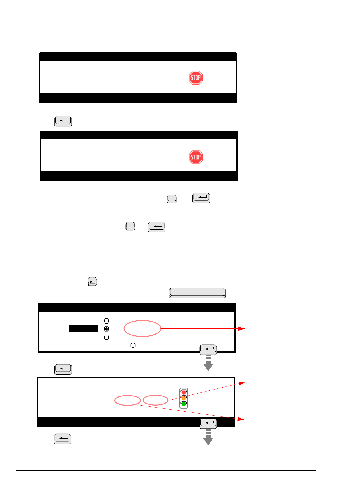
Press to access the marking screen
MARKING :
Enter > Start marking
Press to launch the marking cycle.
:
[ 1
:
:
] times
000 001
USING THE MARKING PROGRAM WITH EXTERNAL KEYBOARD IN "PROGRAMMING" MODE 2 - 25
PRO-PEN (Ref.90703-MDIS4314/0601C0-chap024314.fm.doc)
The following screen will be displayed during marking :
Marking in progress....
MARKING :
Enter >Suspend marking
Press
Marking in progress....
to interrupt the marking cycle, if necessary.
MARKING:
Abandon the current marking? :_
Enter > Suspend marking
Resume marking
Machine return to origins
Return to marking menu screen
Interruption of marking: press on
000 001
000 001
press on
}
then
O
N
then
2.6.2. Marking “n” times
This option will permit you to mark a specified number of times the same marking file.
Press the arrow key
Validate this option by pressing once on the space bar
MARKING : TEST
1 time
n times
infinite
File simulation
Press to access the marking screen
MARKING :
Enter > Start marking
Press to launch the marking cycle
to access this option
:
:
:
[ 20
000 020
] times
Enter the
number of
markings
required in this
entry zone
The number
of parts to
be marked
will appear in
this zone
The number of
parts already
marked will
appear in this
zone
2 - 26 USING THE MARKING PROGRAM WITH EXTERNAL KEYBOARD IN "PROGRAMMING" MODE
(Ref.90703-MDIS4314/0601C0-chap024314.fm.doc) PRO-PEN
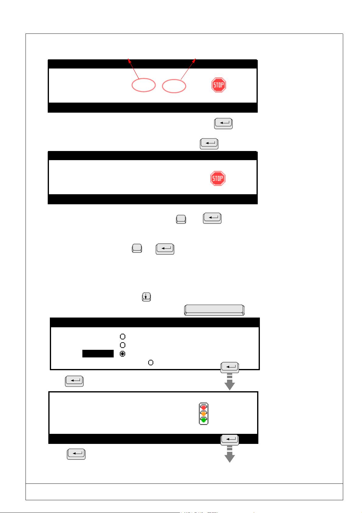
The following screen will be displayed during marking :
Number of parts marked Number of parts to be marked
Marking in progress....
MARKING :
001 020
Enter > Suspend marking
When the marking head returns to the M3000 origin, simply press to mark
the next part or press on the trigger of the M3000.
If you wish to interrupt the marking cycle in progress, press
Marking in progress....
MARKING :
015 020
Abandon the current marking? :_
Enter > Suspend marking
Resume marking
Machine return to origins
press on
N
then
Return to marking menu screen
Interruption of marking: press on
then
O
2.6.3. Infinite standard marking
This option is similar to the “n” times mode, except that the marking will be repeated infinitely.
To access the “infinite” mode, press
Validate this option by pressing once on the space bar
MARKING: TEST
1 time
n times
infinite
File simulation
Press to access the marking screen
MARKING :
Enter > Start marking
:
[
:
]times
:
0
Press to launch the marking cycle
USING THE MARKING PROGRAM WITH EXTERNAL KEYBOARD IN "PROGRAMMING" MODE 2 - 27
PRO-PEN (Ref.90703-MDIS4314/0601C0-chap024314.fm.doc)
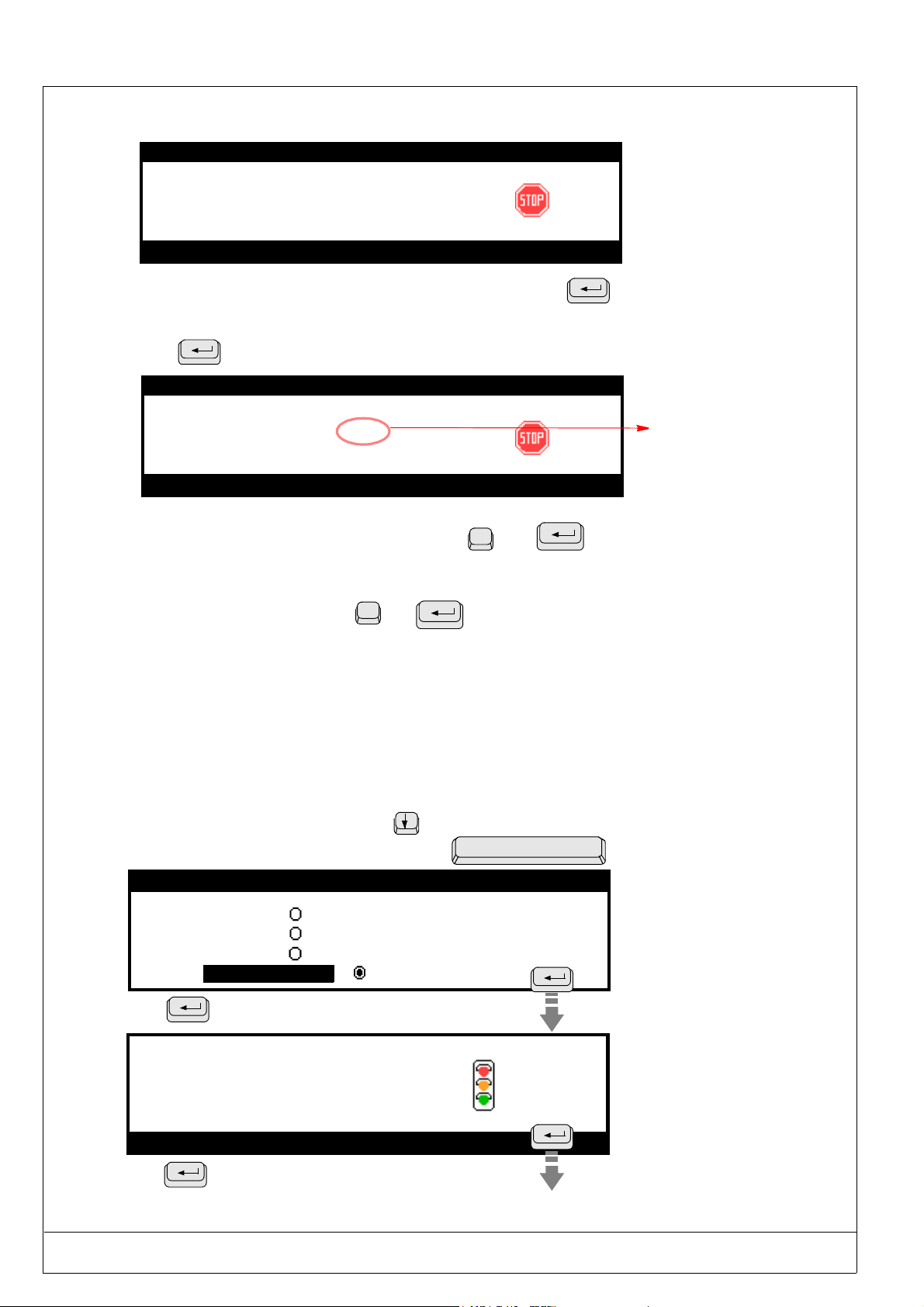
The following screen will be displayed during marking
Marking in progress....
MARKING :
Enter > Suspend marking
0
When the marking head returns to the M3000 origin, simply press to mark the next part
or press on the trigger of the M3000.
Press
Marking in progress....
Abandon the current marking ? :_
Enter > Suspend marking
if you wish to interrupt the marking cycle underway.
MARKING :
143
Number
of parts
marked
Resume marking
N
Machine return to origins
press on
then
Return to marking menu screen
Interruption of marking: press on
then
O
2.6.4. File simulation
This option will permit you to execute a simulation of the marking file. Simulation consists of viewing the rectangles containing the marking blocks (start and end of block).
The marking tool will move without marking the part
To access the “File simulation” option, press
Validate this option by pressing once on the space bar
MARKING: TEST
1 time
n times
infinite
File simulation
Press
To access the marking simulation screen
S I M U L A T I O N
Enter > Start marking
:
[ 1
:
:
] times
:
Press
To access the marking simulation screen
2 - 28 USING THE MARKING PROGRAM WITH EXTERNAL KEYBOARD IN "PROGRAMMING" MODE

(Ref.90703-MDIS4314/0601C0-chap024314.fm.doc) PRO-PEN
Follow the instructions that will appear on the subsequent screens.
The screens shown below will appear one after the other.
Marking in progress....
S I M U LA T I O N
:
Block 1 start position
Pause...
< Space> to continue
Enter > Suspend marking
- The marking tool will move to the start position in the lower left corner of the first character of the first
marking block to be marked.
- Press on the space bar to continue.
Marking in progress....
S I M U LA T I O N
:
Block 1 end position
Pause...
< Space> to continue
Enter > Suspend marking
- The marking tool will move to the start position in the lower right corner of the last character in the
first marking block to be marked.
- Press on the space bar to continue.
Beginning of
the simulation
Beginning of
the simulation
End of the
simulation
End of the
simulation
This procedure will be carried out for each marking block.
When the simulation of the last block is complete, the marking tool will return to the M3000
origin.
The main menu screen will be displayed.
To execute a simulated marking of only one block and not of the whole marking
file, go on this block and press on F4. This key will permit you to rapidly execute
adjustments on a block without systematically simulating the whole marking file.
USING THE MARKING PROGRAM WITH EXTERNAL KEYBOARD IN "PROGRAMMING" MODE 2 - 29

PRO-PEN (Ref.90703-MDIS4314/0601C0-chap024314.fm.doc)
2.7) “File manager” Menu
This menu will permit you to make modifications on the existing files :
• Opening a file for marking,
• Opening a file for modification,
• Deleting a file.
Select this menu using the arrows
Open
a file
Select the open / delete option using the arrow
Press
to validate.
or TAB
keys. Press
or TAB .
Esc
keys.
to validate.
H
Delete
a file
The screen shown below contains the list of all files in the command board’s memory.
- Open a file- 99. 0 % Free
- Open a file- 99. 0 % Free
001 TEST
002 TEST2
010 TEST3
050 TEST4
250 TEST5
This figure indicates the percentage
of remaining memory space, in
relation to the amount available at
the beginning (50Kb).
The files are arranged by an ascending number order.
If you have saved more than 5 files, a pull-down bar will appear on the right of the screen. It will indicate that
you may access the other files using the
Select the file to be opened or deleted using the arrow keys. Press
arrows.
to validate.
2 - 30 USING THE MARKING PROGRAM WITH EXTERNAL KEYBOARD IN "PROGRAMMING" MODE

(Ref.90703-MDIS4314/0601C0-chap024314.fm.doc) PRO-PEN
.
2.7.1. Opening a file for marking
Select the file to be opened using the arrows keys. Press et valid to validate.
- Opening a file- 99. 0 % Free
001 TEST
002 TEST2
010 TEST3
050 TEST4
250 TEST5
When the file is open, press to return to the main menu.
Continue as directed in the “Marking” chapter
(see page 2-28).
2.7.2. Opening a file to make and save modifications
Select the file to be opened using the arrow keys. Press et valid to validate.
-Opening a file- 99. 0 % Free
-Opening a file- 99. 0 % Free
001TEST
002 TEST2
010 TEST3
050 TEST4
250 TEST5
When the file is open, proceed to make the necessary modifications.
The file name will then be followed by a star : *
Case one
Press
Esc
to exit. The following message will appear .
Save modifications ?
Confirm Esc/y/n : _
Esc : Return to the file without
saving the modifications.
n : Return to the main menu
without saving the modifications
y : Save
The following screen will appear :
Number of the file
010*
Enter file number [0 999] :
File comments
in 3 characters
Comments on the
file using 32
characters.
Enter the new file name : this will replace the existing file name.
Enter file comments (optional), for example, the description of the part or the type of marking.
USING THE MARKING PROGRAM WITH EXTERNAL KEYBOARD IN "PROGRAMMING" MODE 2 - 31

PRO-PEN (Ref.90703-MDIS4314/0601C0-chap024314.fm.doc)
If an existing file name is entered, the following message will appear :
y : Save the file with the modifications
made to the old file version
010
Replace file
Existing file !
(y/n) : _
n : Return to main menu
If the response is "y", the following screen will appear if the file is to be over written or a new number
given:
010
Enter file number [0 999 ] : 010
194 Bytes
File comments
MARKING TEST
File saved
Exit: [ ESC ]
Press ESC to return to the main menu.
Case two
Press F11 to save the modifications.
Follow the two procedures below :
- Enter the new file number, this will replace the existing file name. Press "ENTER" to validate.
- Enter the file comments (optional).
010*
Enter file number [0 999] : 010
File comments
MARKING TEST
If the file name already exists in the memory, the following message will appear :
y : Save the file with the modifications
made to the old file version
010
Replace file
Existing file !
(y/n) : _
n : Return to main menu
If the response is "y", the following screen will appear if the file is to be over written or a new number
given:
010
Enter file number [0 999 ] : 010
194 Bytes
File comments
MARKING TEST
File saved
Exit : [ ESC ]
Press ESC to return to the main menu.
2 - 32 USING THE MARKING PROGRAM WITH EXTERNAL KEYBOARD IN "PROGRAMMING" MODE

(Ref.90703-MDIS4314/0601C0-chap024314.fm.doc) PRO-PEN
2.7.3. Deleting a file
Select the file to be deleted using the arrow keys. Press validez
-Deleting a file- 99. 0 % Free
-Deleting a file- 99. 0 % Free
TTTTTtttEttSTTTST
001TEST
TTTESTTESTEST
002TEST2
010TEST3
050TEST4
250TEST5
to validate.
The program will ask for confirmation as a safety measure :
DELETE FILE 001
Confirmation
Esc/ y / n : _
Esc : Return to main menu without deleting the file.
y : Delete the file and return to the main menu.
n : Return to the main menu without deleting the file
USING THE MARKING PROGRAM WITH EXTERNAL KEYBOARD IN "PROGRAMMING" MODE 2 - 33

PRO-PEN (Ref.90703-MDIS4314/0601C0-chap024314.fm.doc)
2.8) Communication with the PC” menu (optional)
This menu is optional and only functions with the PW03 marking program, or the back-up program for PW02
files.
Use this menu to transfer information :
• From a PC to the internal program of the M3000 command board,
• From the command board to the M3000.
Access this menu using the arrow or TAB
PC COMMUNICATION
Command :
Data transmission indicator (direction: PC/Machine or Machine/PC).
The indicator will flash when data is being transmitted.
keys. Press to validate.
H
If you are using this option, please refer to the operating manual included with the"PW03 Program" .
2 - 34 USING THE MARKING PROGRAM WITH EXTERNAL KEYBOARD IN "PROGRAMMING" MODE

(Ref.90703-MDIS4314/0601C0-chap024314.fm.doc) PRO-PEN
2.9) “Configuration” Menu
This menu will permit you to access the various parameters for marking configuration
Select this menu using the arrow keys . Press or TAB
The configuration parameters will appear on three subsequent screens.
Use the arrow
keys to move from one screen to the other.
- CONFIGURATION -
Function mode
H
Machine temporization
File parameters
System variables
Setting the date/time
to validate.
H
Esc
- CONFIGURATION -
Language
List of available fonts
List of available logos
Wear and tear counter configuration
Machine characteristics
- CONFIGURATION -
Dialogue configuration
Select a parameter using the arrow
Esc
Esc
keys. Press to validate.
USING THE MARKING PROGRAM WITH EXTERNAL KEYBOARD IN "PROGRAMMING" MODE 2 - 35

PRO-PEN (Ref.90703-MDIS4314/0601C0-chap024314.fm.doc)
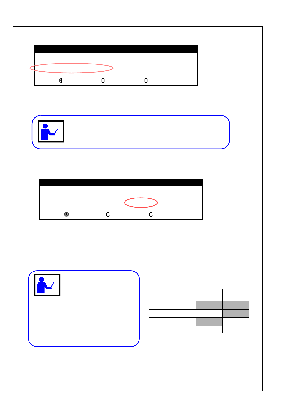
2.9.1. Function mode
Select this parameter using the arrow
keys. Press to validate.
- CONFIGURATION -
Function mode
Machine temporization
File parameters
System variables
Setting the date/time
Function mode OPERATOR (L)
Function mode SUPERVISOR (H)
Select the function mode using the arrow keys. Press
There are two function modes available :
• operator - represented by the letter : L : Access limited to certain program functions,
• supervisor - represented by the letter : H : Access to all program functions.
H
Esc
to validate.
The operator mode will allow restricted operating of the program for creation of simple files. The following menus are
not available in this mode:
• Radial marking • Language
• Angular marking • List of available fonts
• File parameters, • List of available logos,
• System variables, • Machine characteristics.
• Setting the date/time,
2 - 36 USING THE MARKING PROGRAM WITH EXTERNAL KEYBOARD IN "PROGRAMMING" MODE

(Ref.90703-MDIS4314/0601C0-chap024314.fm.doc) PRO-PEN
2.9.2. Machine temporization
Select this parameter using the keys and validate with
- CONFIGURATION -
Function mode
Temporisation machine
Machine temporization
File parameters
System variables
Setting the date/time
Esc
Pneumatic marking tool
Raising time:
Lowering time:
Marking speed:
Movement speed:
20.0 ms
20.0 ms
33 mm/s
110 mm/s
Delays
It is possible to adjust the values of the delays to adapt the machine to the particularities of some applications.
It is nevertheless strongly recommended to use the values defined by default.
The modification of the delays will affect the files contained in the machine’s
memory.
•
Speeds
The marking and movement speeds displayed on the screen are the reference speeds programmed by default
(intermediate speeds).
Position the cursor using the "up" and "down’ arrows on the keyboard to modify and enter the new value.
These speeds can be personalized. In this case, select the marking in the "intermediate speed’ mode.
Value of the speeds programmed by default:
Speed: Marking quality Intermediate Cycle time
Marking - 20% of the reference
value
Moving - 40% of the reference
value
Reference value + 20% of the reference
value
Reference value + 40% of the reference
value
• The speed modifications will affect all the files contained in the machine’s
memory.
• The modification of a reference speed will bring about the automatic modification of the
speed related to the cycle time as well as that related to the quality of the marking.
USING THE MARKING PROGRAM WITH EXTERNAL KEYBOARD IN "PROGRAMMING" MODE 2 - 37

PRO-PEN (Ref.90703-MDIS4314/0601C0-chap024314.fm.doc)
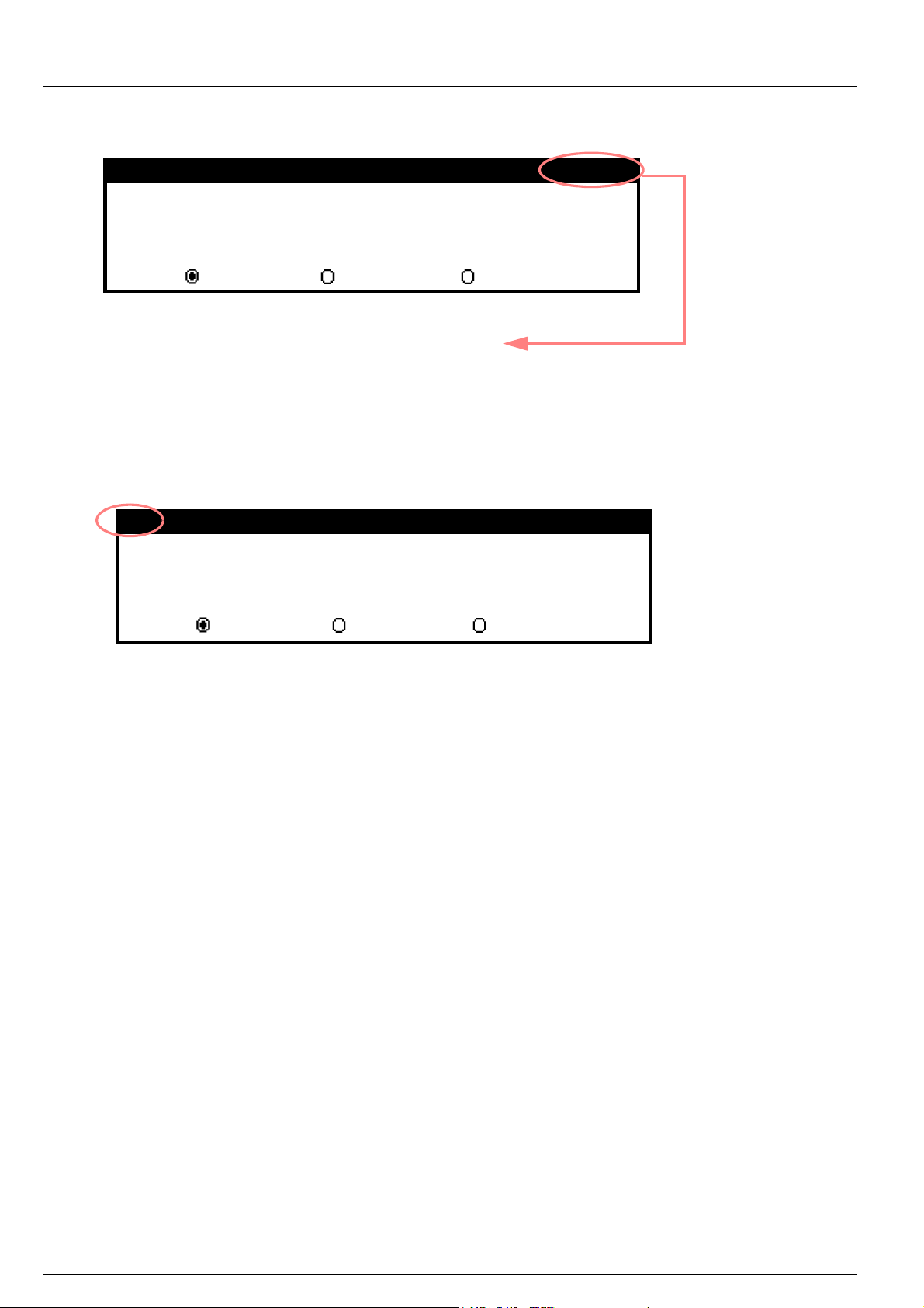
2.9.3. File parameters
This menu can only be accessed in the "supervisor" mode.
Select this parameter using the arrow
- CONFIGURATION -
Function mode
Machine temporization
File parameters
File parameters
System variables
Setting the date/time
File parameters
Units
Off-limit control
Character case
Move between the various options using the arrow
Press the space bar to activate or deactivate a parameter.
mm
keys. Press to validate.
H
Esc
inches
keys.
Press
to validate the activation/deactivation of a parameter.
These parameters apply to ALL of the marking files.
The choice of the "inch" unit will bring about the conversion in ALL of the files.
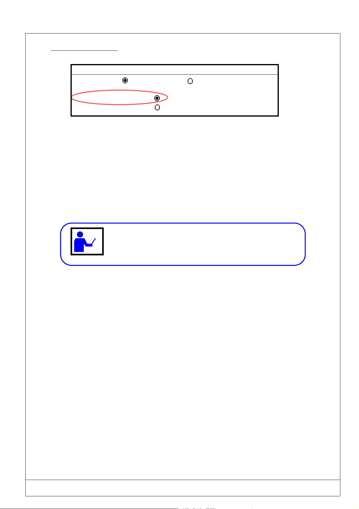
2.9.3.1 - Units
File parameters
Unit
Off-limit control
Character case
The marking program may be set to use either inches or millimeters as the unit of measurement. All the values giving
measurements of length as well as the size of the characters willbe given in the selected unit of measurement.
mm
inches
When the unit of measurement changes, all the values contained within the marking files
will automatically be converted.
2 - 38 USING THE MARKING PROGRAM WITH EXTERNAL KEYBOARD IN "PROGRAMMING" MODE
(Ref.90703-MDIS4314/0601C0-chap024314.fm.doc) PRO-PEN
2.9.3.2 - Off-limit control
File parameters
Units
mm
inches
Off-limit control
Character case
This parameter will always be activated by default.
• if the marking goes off limits, the program will send an error message,
• the calculation time (and therefore the cycle running time) will be extended.
It is recommended that you use this option only when updating the marking files.
When the off-limit control is deactivated :
• the marking tool can hit the mechanical stops if the text is too long, or if the coordinates are incorrect,
• The calculation and cycle running times will be shorter.
It is recommended that the file be prepared with the "Off-limits control"
option activated and then be deactivated when the preparation has been
finished.
The examples on the following pages show texts that are off-limits
USING THE MARKING PROGRAM WITH EXTERNAL KEYBOARD IN "PROGRAMMING" MODE 2 - 39

PRO-PEN (Ref.90703-MDIS4314/0601C0-chap024314.fm.doc)
• Example: Off-limits on the X axis
Marking file
*
X : 50.00 Y : 20.00 [mm]
Text : ABCDE 12345
Size : 8.00 [mm] Stroke : 2
Linear Angular Radial
• Machine movements:
X = 60 mm
Y = 40 mm
• Coordinates of text to be marked:
X = 50 mm
Y = 20 mm
• Character size = 8 mm
• Text length = 48.40 mm
In the given example it is necessary top modify the
value of X, the size of the characters, or reduce the
text to be marked.
Press on any key to return to the main menu.
0
0
10
20
Y
Possible error message
Press any key ....
Bloc : 1/1
10 20 30 40 50X60
Bloc k 1 text off-limits..
along X
• Example: off-limit on the Y axis
Marking file
TEST5 Block : 1/1
X : 35.00 Y : 30.00 [mm]
Text : ABCDE 12345
Size : 8.00 [mm] Stroke : 2
Angle : 90° Radius : 30
Linear Angular Radial
• Machine movments:
X = 60 mm
Y = 40 mm
• Coordinates of text to be marked:
X = 35 mm
Y = 30 mm
Radius = 30 mm
• Character size = 8 mm
• Text height = 42.17 mm
possible error message
10 20 30 40 50
10
20
30
Y
In this example it is necessary to modify the value of Y and the size of th characters to be marked.
Press on any key to return to the main menu.
Press any key....
Block 1 text off-limits.
along Y
X
2 - 40 USING THE MARKING PROGRAM WITH EXTERNAL KEYBOARD IN "PROGRAMMING" MODE
(Ref.90703-MDIS4314/0601C0-chap024314.fm.doc) PRO-PEN
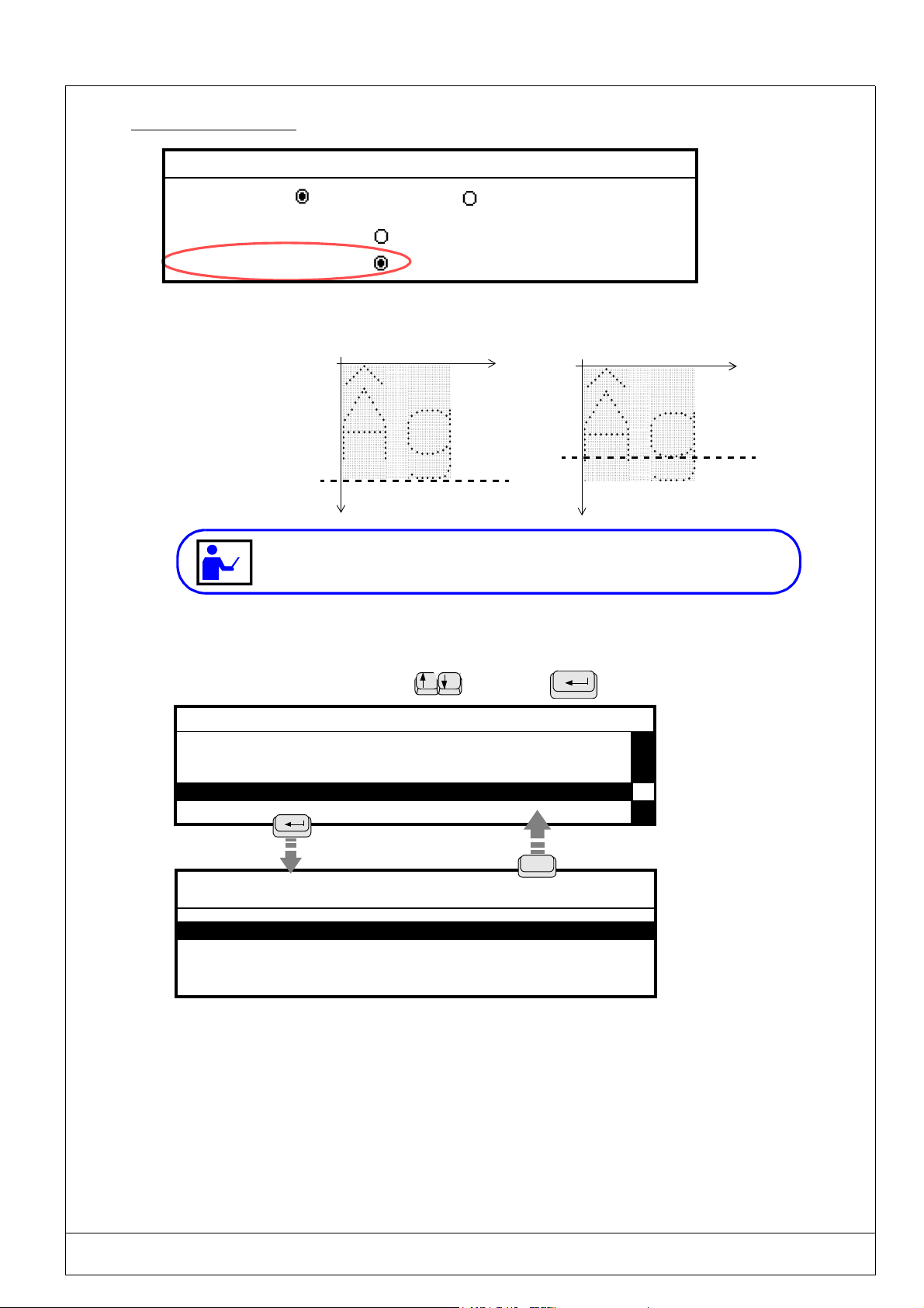
2.9.3.3 - Character case
File parameters
Units
mm
inches
Off-limit control
Character case
For lower case letters, the extra space necessary for downstoke characters (such as p,g...) will be taken into consideration
by the program.
X
X
Y
difference when
marking capital
letters
Y
Activated character case
Deactivated character case
When the character case mode is activated and a capital letter text is to be marked,
this text will be shifted on the Y axis according to the required Y coordinate .
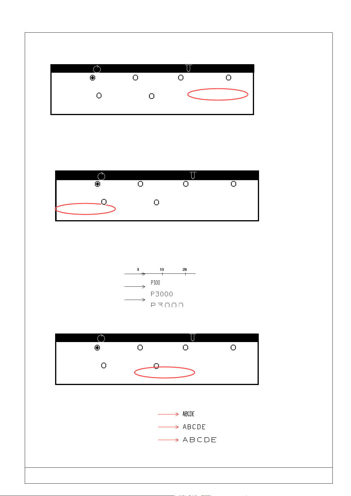
2.9.4. System variables
Select this parameter using the arrow
- CONFIGURATION -
Function mode
Machine temporization
File parameters
System variables
System variables
Setting the date / time
keys. Press to validate.
The system variables
apply to all marking
Esc
System variables
Counter Configuration
Shift Configuration
Days/Months/Years Format Configuration
Variable Configuration
These parameters will permit you to personalize marking using the following functions :
- Counters : these counters are used for the increment / decrement function of a serial number.
- Shift : this parameter will permit you to determine the texts to be marked according to the current hour.
- Day/Month/Year option : this parameter will permit you to define personalized formats for marking the months, years,
and days.
- Variables : this parameter will permit you to mark repetitive texts common to several marking files.
files.
USING THE MARKING PROGRAM WITH EXTERNAL KEYBOARD IN "PROGRAMMING" MODE 2 - 41
PRO-PEN (Ref.90703-MDIS4314/0601C0-chap024314.fm.doc)
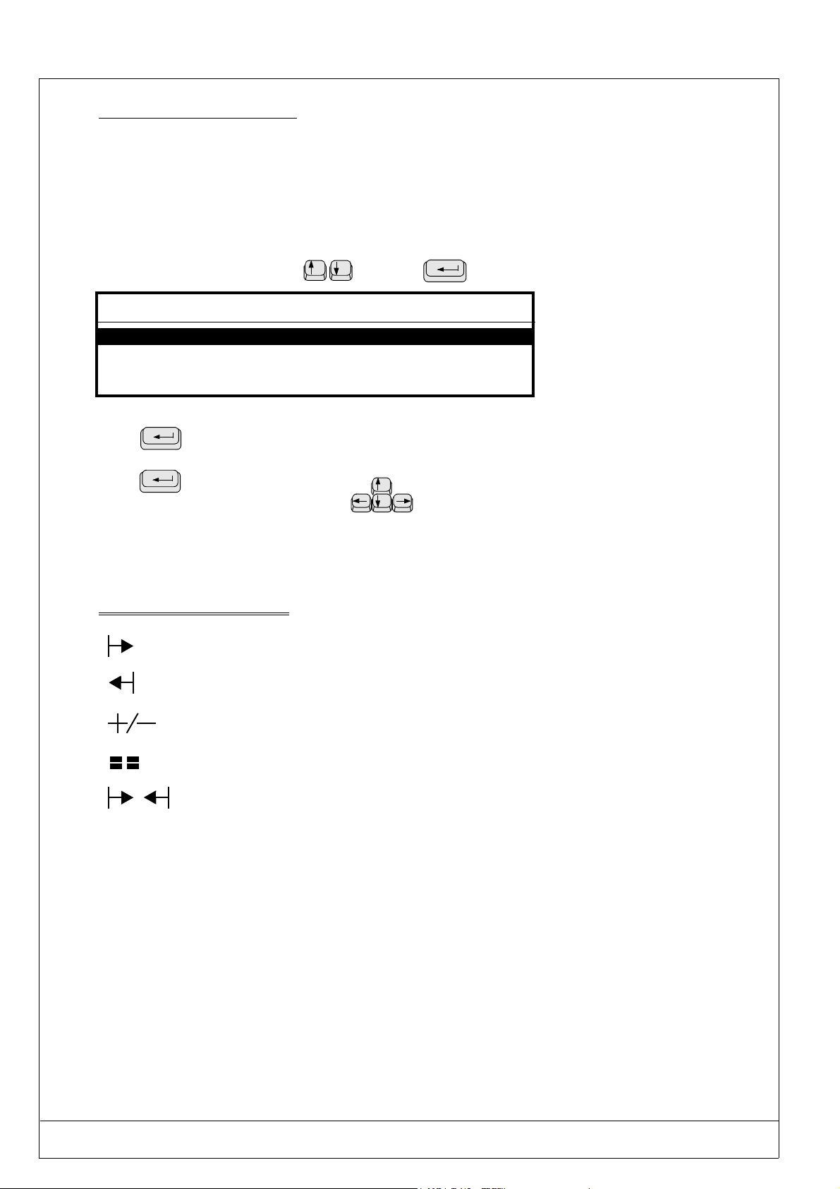
2.9.4.1 - Counter Configuration
These counters are used for the increment / decrement function. Data may be marked using
either the numeric or alphanumeric mode. Eight independent counters are available for a marking file.
Each counter has a code made up of 8 digits.
The “keywords” for identification are K0 to K7.
The counters are parametered in the sub-menu “Counter configuration”, found in the “System variables” menu.
Select this parameter using the arrow
System variables
Counter Configuration
Shift Configuration
Days/Months/Years Format Configuration
Variable Configuration
To enter data :
Press
Enter the data,
Press
Move between entry zones using the arrow
Description of the symbols used
to validate an entry zone,
to validate.
Gives the value of the counter at the beginning.
keys. Press to validate.
keys.
Gives the value of the counter at the end.
Gives the value of the increment.
Gives the value of the batch or the number of the entry.
Gives the value of the counter during marking.
2 - 42 USING THE MARKING PROGRAM WITH EXTERNAL KEYBOARD IN "PROGRAMMING" MODE
(Ref.90703-MDIS4314/0601C0-chap024314.fm.doc) PRO-PEN
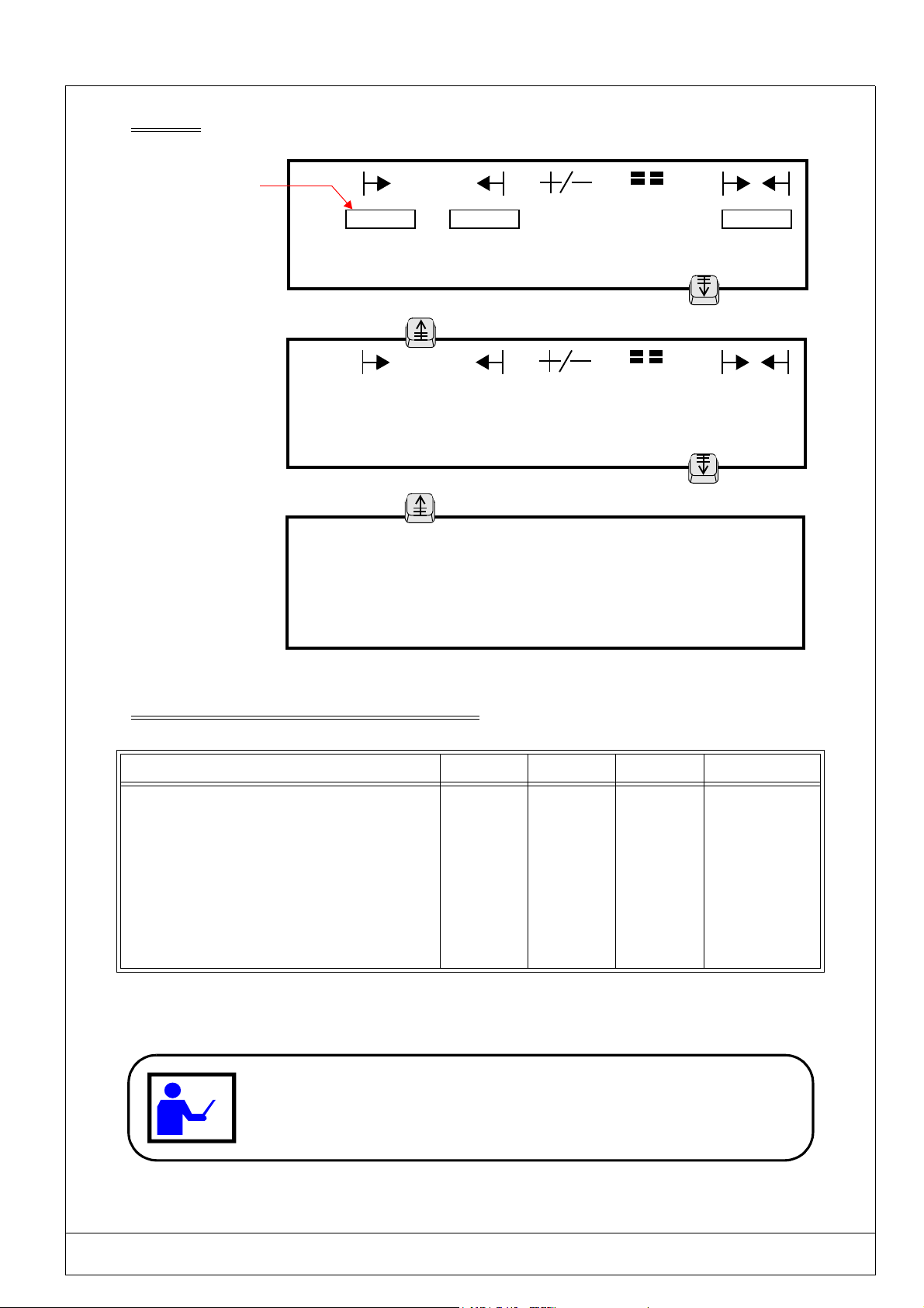
Utilization
Typing area:
8 characters max
K0 :
K1 :
01
01
K2 : 001 999 1 1 356
K3 : 000 400 2 1 098
Page Down
Page Up
K4 :
K5
K6:
50 00
- 1 1
01
01
45
K7: 1A 9Z 1 2 5B
Page Down
Page Up
K0 :
K1 :
K2 :
K3 :
MM DD hh mm
# # # # # # # #
# # # # # # # #
# # # # # # # #
# # # # # # # #
K4 :
K5 :
K6 :
K7 :
MM DD hh mm
# # # # # # # #
# # # # # # # #
# # # # # # # #
# # # # # # # #
Explanatory description of the 3 screen shown above
N°of the counter K2 K3 K4 K7
The values given are: Numeric Numeric Numeric Alphanumeric
The next number to be marked is : 356 098 45 5B
The start marking value was : 001 000 50 1A
The end value will be : 999 400 00 9Z
The increment / decrement will be : 1 2 - 1 1
Number of parts to be marked with the same number : 1 1 1 2
DECREMENT FUNCTION
The decrement function may be obtained by entering an end value lower than the start
value. For exam
ple, for the K4 counter below, there will be a decrementing of the
number because the start value is higher than the end value.
USING THE MARKING PROGRAM WITH EXTERNAL KEYBOARD IN "PROGRAMMING" MODE 2 - 43
PRO-PEN (Ref.90703-MDIS4314/0601C0-chap024314.fm.doc)
Initialization of the counters
The screen shown below will permit you to determine an hour or date when the counters will return to their start
.
values.
MM DD hh mm
K0 :
K1 :
K2 :
K3 :
# # # # # # # #
# # # # # # # #
# # # # # # # #
# # # # # # 0 0
RAZ every hour
The reset of a counter to 0 (RAZ) will be common to all the marking files.
Example of a marking file
X : 10 Y : 10 [mm]
Text : @K2@
Size : 3 [mm] Stroke : 2
MM DD hh mm
K4 :
K5 :
K6 :
K7 :
# # # # 0 0 0 0
# # # # # # # #
# # 0 1 0 0 0 0
0 1 0 1 0 0 0 0
RAZ on January 1st at 00:00
(i.e. once a year)
RAZ everyday at 00:00
RAZ on the 1st of each month
Marking obtained
X
Linear Angular Radial
Y
2 - 44 USING THE MARKING PROGRAM WITH EXTERNAL KEYBOARD IN "PROGRAMMING" MODE

(Ref.90703-MDIS4314/0601C0-chap024314.fm.doc) PRO-PEN
2.9.4.2 - Shift configuration
This parameter is used to determine the texts to be marked, in order to identify the working shifts according to the current
hour.
Shift configuration is possible each day of the week within 5 time slots.
The “keyword” for identification is Q.
The time used is that of the M3000.
Select this parameter using the arrow keys. Press
System variables
Counter Configuration
Shift Configuration
Days/Months/Years Format Configuration
Variable Configuration
to validate.
START END SUNDAY
1 :
00 : 00 00 : 00
2 :
00 : 00 00 : 00
CODE
3 : 00 : 00 00 : 00
4 : 00 : 00 00 : 00
5 : 00 : 00 00 : 00
Page Up
START END MONDAY
1 :
00 : 00 05 : 59
2 :
06 : 00 13 : 59
3 : 14 : 00 20 : 00
4 : 20 : 01 23 : 59
CODE
Night shift
Morning
Shift 3
Evening shift
5 : 00 : 00 00 : 00
To enter data :
Press
to validate an entry zone,
Enter data,
Press
to validate.
Move between entry zones using the arrow
Typing area:
20 characters max.
Page Down
keys.
In the example shown above, the marking carried out on Monday will be :
• "Night shift" from 00:00 mn 00 s. to 05:59 mn 59 s.
• "Morning" from 06:00 mn 00 s. to 13:59 mn 59 s.
• "Shift 3" from 14:00 mn 00 s. to 20:00 mn 59 s.
• "Evening shift" from 20:01 mn 00 s. to 23:59 mn 59 s.
USING THE MARKING PROGRAM WITH EXTERNAL KEYBOARD IN "PROGRAMMING" MODE 2 - 45
PRO-PEN (Ref.90703-MDIS4314/0601C0-chap024314.fm.doc)
.
Marking file executed at 5:00 pm:
Marking obtained
X
*
X : 5.00 Y : 5.00 [mm]
Text : @Q@
Size : 2.00 [mm] Stroke : 2
Block : 1/1
Linear Angular Radial
When choosing the shifts schedule make sure that there is no overlapping of hours.
This means that the end of one is not the beginning of the next one.
Y
2 - 46 USING THE MARKING PROGRAM WITH EXTERNAL KEYBOARD IN "PROGRAMMING" MODE

(Ref.90703-MDIS4314/0601C0-chap024314.fm.doc) PRO-PEN
2.9.4.3 - Days/Months/Years Format Configuration
These parameters will permit you to define a code for identifying the days of the week, the months as well as the 5 next
year, so that the marking is personalized.
Select this parameter using the arrow keys. Press
System variables
Counter Configuration
Shift Configuration
Days/Months/Years Format Configuration
Variable Configuration
Use these arrow keys to access / exit from
•
the three days/months/years data entry screens
To enter data :
•
Press
to validate an entry zone,
Enter data,
Press
Move between entry zones using the arrow
to validate.
keys.
DAYS / CORRESPONDING CODES
Sunday
Monday
Tuesday : Saturday :
Wednesday :
: Thursday :
SUN
: Friday :
Mon
02
04
05
SAT
Wednesday
to validate.
Esc
Code entry zone
(Maximum : 8 characters)
MONTHS / CORRESPONDING CODES
01
02
03
04
-AFEB
03
April
050605-May
JUNE
J-07
07
AUG
08
Code entry zone
(Maximum : 10 characters)
YEARS / CORRESPONDING CODES
2000
2001
00
01
2002 C21-Y1
2003 C21-Y2
2004
Code entry zone
(Maximum : 9 characters)
09
10
11
12
S-09
OCT
NOV
12
Esc
Esc
USING THE MARKING PROGRAM WITH EXTERNAL KEYBOARD IN "PROGRAMMING" MODE 2 - 47

PRO-PEN (Ref.90703-MDIS4314/0601C0-chap024314.fm.doc)
The “keywords” are :
- DS for days,
- MS for months,
- YS for years.
Example using codes on the previous page :
Marking file
(marking carried
out on Wednesday,
February 7, 2001)
Marking obtained
*
X : 5.00 Y : 5.00 [mm]
Text : @"Lyon "DS DD-MS/YS@
Size : 2.00 [mm] Stroke : 2
Linear Angular Radial
X
Y
Block : 1/1
2 - 48 USING THE MARKING PROGRAM WITH EXTERNAL KEYBOARD IN "PROGRAMMING" MODE

(Ref.90703-MDIS4314/0601C0-chap024314.fm.doc) PRO-PEN
2.9.4.4 - Variable Configuration
It is possible to save and load repetitive texts that are common to several marking files by entering the number given to
each variable.
The variables are in memory spaces (10 in total) that can contain texts made up of 32 characters max.
These are common to all the marking files.
They may be identified by their key words V0 to V9.
System Variables
Counter Configuration
Shift Configuration
Days/Months/Years Format Configuration
Variable Configuration
Variable Configuration
V0 :
Variable Configuration
V1 : ABCDE0123
V9 : XYZ789
Enter a text in the
selected variable
Each press on the
ENTER key will access
the next variable.
Variable Configuration
Always validate the contents of a
variable so that it is saved.
ESC
System Variables
Counter Configuration
Shift Configuration
Days/Months/Years Format Configuration
Variable Configuration
USING THE MARKING PROGRAM WITH EXTERNAL KEYBOARD IN "PROGRAMMING" MODE 2 - 49

PRO-PEN (Ref.90703-MDIS4314/0601C0-chap024314.fm.doc)
Programming in a marking file
*
X : 10.00 Y : 10.00 [mm]
Text : @V1@
Size : 3.00 [mm] Stroke : 2
Linear Angular Radial
The marking obtained with the coordinates X=10mm and Y=10mm will be contained in the V1 variable : ABCDE0123
Concatenation of variables
It is possible to program several variables in a same syntax .
*
X : 10.00 Y : 10.00 [mm]
Text : @V0 V2 V5 V8@
Size : 3.00 [mm] Stroke : 2
Linear Angular Radial
Block : 1/1
Block : 1/1
In the above example:
• Contents of V0 = Marking
• Contents of V2 = of
• Contents of V5 = four
• Contents of V8 = variables
The marking obtained with the coordinates X=10mm and Y=10mm will be : Marking of four variables
• The maximum length of the concatenated text is 200 characters.
• This command will permit you to mark a ECC200 Data Matrix code of 200 characters.
Saving in a variable
A text or a word may be saved in a variable by using the syntax :
@VS(text;v)@ :
text : This area is used to enter text. The text may be fixed or a key word.
v : Number of the variable in which the text area is saved.
separator :
; (semi colon) .
This syntax will permit you to make two identical markings on a same part using the "hours, minutes,
seconds" format.
2 - 50 USING THE MARKING PROGRAM WITH EXTERNAL KEYBOARD IN "PROGRAMMING" MODE

(Ref.90703-MDIS4314/0601C0-chap024314.fm.doc) PRO-PEN
Example 1 : Saving a text
Block : 1/2
X : 0.00 Y : 0.00 [mm]
Text : @VS(TECHNIFOR;2)@
Size : 0.50 [mm] Stroke : 2
Linear Angular Radial
F5
Block : 2/2
X : 0.00 Y : 10.00 [mm]
Text : @V2@
Size : 3.00 [mm] Stroke : 2
Linear Angular Radial
The marking obtained with the coordinates X=10mm and Y=10mm will be : TECHNIFOR
Example 2 : Saving a "time" format
*
X :10.00 Y : 10.00 [mm]
Text : @VS(@hhmmss@;2)@
Size : 3.00 [mm] Stroke : 2
Linear Angular Radial
X : 10.00 Y : 10.00 [mm]
Text : @V2@
Size : 3.00 [mm] Stroke : 2
Linear Angular Radial
X : 30.00 Y : 60.00 [mm]
Text : @V2@
Size : 5.00 [mm] Stroke : 2
Block : 1/9
F5
Block : 2/9
F5
F5
F5
Block : 9/9
Linear Angular Radial
The "hours minutes seconds" format marked in the block n° 9 is identical to the format marked in block n° 2.
USING THE MARKING PROGRAM WITH EXTERNAL KEYBOARD IN "PROGRAMMING" MODE 2 - 51

PRO-PEN (Ref.90703-MDIS4314/0601C0-chap024314.fm.doc)
2.9.5. Setting the Date/Time/"Julian" date
Summer/winter daylight saving time is not automatic.
This parameter will permit you to:
• Update the internal clock of the machine’s command board,
• Determine the time at which the day of the month will be changed (number of the day in the year)
2.9.5.1 - Updating the clock
Select using the
- CONFIGURATION -
Operating mode
Temporization machine
File parameters
System variables
Setting the date/hour
keys then validate using
Command board’s
internal date
Command board’s
internal day of the month
DATE / HOUR SYSTEM
DATE : 28/05/2002
Enter the new date :
HOUR : 10:37:23 Format 24H
Enter the new Hour :
Board’s current hour Typing area to enter the new hour: hh:mm:ss
[
Wednesday
Esc
Automatic updating of parameter
]
when the date has been changed
Typing area for the new date
Cumpulsory format : DD/MM/YYYY
24 : hours from noon to midnight
13-14-15....will be written
(only format used)
2 - 52 USING THE MARKING PROGRAM WITH EXTERNAL KEYBOARD IN "PROGRAMMING" MODE

(Ref.90703-MDIS4314/0601C0-chap024314.fm.doc) PRO-PEN
2.9.5.2 - Setting the "Julian" date- Summer/winter daylight saving time
Access the screen for hour updating, then press
DATE / HOUR SYSTEM
DATE : 28/05/2002
Enter the new date :
HOUR : 10:37:23 Format 24H
Enter the new Hour :
Page Up
Clock parameters
Changing the "Julian" date: 05 :00 :00
Summer/winter daylight saving time
Display time
[
Wednesday]
Page Down
• Changing the "Julian" date
In the example shown above, the change of day will be done every day at 05:05 A.M.
Marking done on Wednesday May 29, 2002 (29/05/2002), following the @CCC@ syntax:
A 03 : 00 marking number : 148,
A 05 : 00 marking number : 149.
• Summer/winter daylight saving time
The automatic change of hour is based on the French schedule:
. Change from summer to winter daylight saving time
: the last weekend in October, in the night
between Saturday and Sunday.
. Change from winter to summer daylight saving time
: the last weekend in March, in the night
between Saturday and Sunday.
Activate the radio button placed in front of "Summer/winter daylight saving time", by using the space bar
on the machine’s keyboard to validate this function.
• Displaying the date and time during marking
In order to display the date and time on the screen during marking, activate the radio button positioned in
front of "Display time", by using the space bar on the machine’s keyboard to validate this function.
USING THE MARKING PROGRAM WITH EXTERNAL KEYBOARD IN "PROGRAMMING" MODE 2 - 53

PRO-PEN (Ref.90703-MDIS4314/0601C0-chap024314.fm.doc)
2.9.6. Language
This option will permit you to instantly obtain the translation of the program in other languages.
Select this parameter using the arrow keys. Press
- CONFIGURATION -
Language
List of available fonts
Wear and tear counter configuration
Machine characteristics
LANGUAGES
Français
English
Deutsch Italiano
to validate.
Esc
Example of a screen in French
DATE / HEURE SYSTEME
DATE : 11/02/2001
Entrer la nouvelle date :
HEURE : 11h01mn51s Format 24h
Entrer la nouvelle Heure :
Mercredi]
[
Example of a screen in English
SYSTEM DATE / TIME
DATE : 02/11/2001
Enter the new date :
TIME : 11:01:51 24h format
Enter the new time :
[
Wednesday]
Should you wish to work in inches, access the "File parameters"
menu to change the unit after having selected the language. See 2.9.3.1.
2 - 54 USING THE MARKING PROGRAM WITH EXTERNAL KEYBOARD IN "PROGRAMMING" MODE
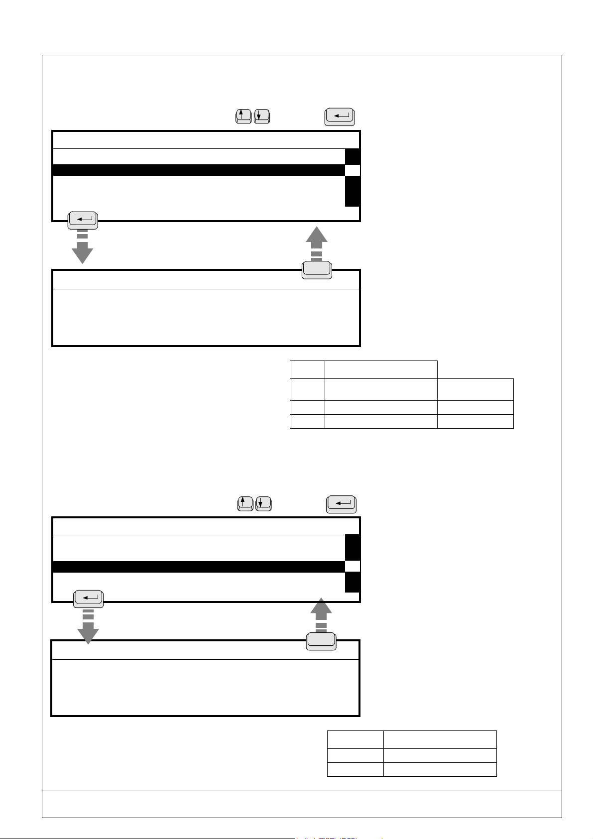
(Ref.90703-MDIS4314/0601C0-chap024314.fm.doc) PRO-PEN
2.9.7. List of available fonts
This option will display the available fonts stored in the memory. Each font is represented by a number.
Select this parameter using the arrow keys. Press
- CONFIGURATION Language
List of available fonts
List of available logos
Wear and tear counter configuration
Machine characteristics
FONTS
xstd200 N°0
xpts200
x57c200
N°1
N°3
The font characters are programmed in the command
board of the machine.
Two fonts are available in the basic pneumatic
configuration
See chart opposite.
to validate.
Esc
N° Contents
0 Standard characters of very high
legibility
1 Characters of very high legibility dot / dot
3 Standardized characters 5 x 7 dot / dot
REMARK
If you have ordered other fonts
such as OCR, they will also be
shown in the list.
If you have ordered the
"Downloading" option, please
see chapter 2.8)
Continous stroke
2.9.8. List of available logos
This option will display the available logos. Each logo is represented by a number.
Select this parameter using the arrow keys. Press
- CONFIGURATION -
Language
List of available fonts
List of available logos
Wear and tear counter configuration
Machine characteristics
Esc
L O G O S
LOGO98
LOGO99
The logos are programmed on the M3000’s command board. A
logo is available in the basic configuration. See chart opposite.
to validate.
REMARK
If you have ordered other logos,
these will appear on the list as
well.
Name Contents
LOGO98 CE Logo - separated dots
LOGO99 CE Logo - dot by dot
USING THE MARKING PROGRAM WITH EXTERNAL KEYBOARD IN "PROGRAMMING" MODE 2 - 55
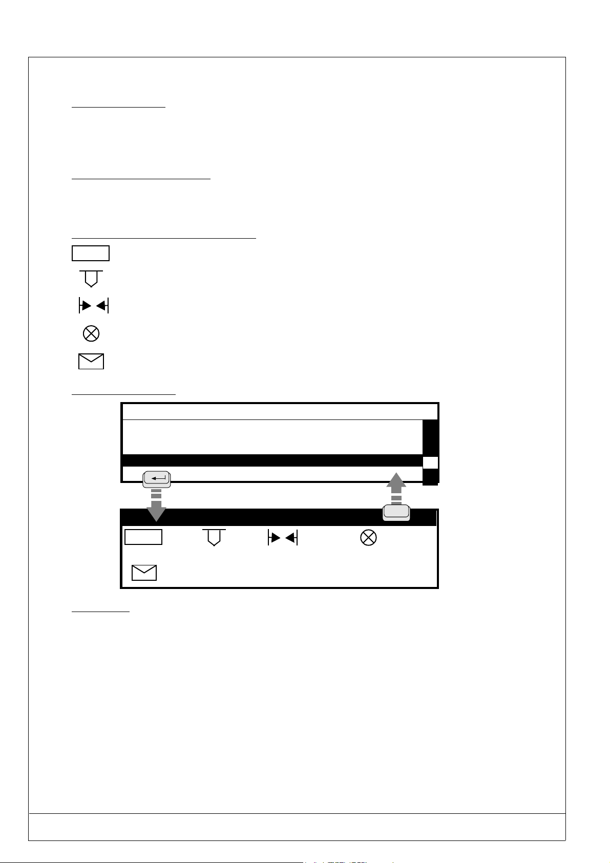
PRO-PEN (Ref.90703-MDIS4314/0601C0-chap024314.fm.doc)
2.9.9. Wear and tear counter configuration
2.9.9.1 - Description
This counter will permit you to calculate the distance run by a pneumatic stylus.
Only the distance run by the stylus when it is activated will be calculated.
The movements between blocks will not be taken into account.
2.9.9.2 - Units of measurement
The unit of measurement used is the meter (metric system).
When the machine is activated in the inch mode, the unit of measurement used will be the yard (0.9144m).
2.9.9.3 - Description of the symbols used
INITO
Zero reset for the counter calculating the distance run.
Value of the order after which a message is displayed and/or an output is activated.
Distance run.
Number of the output
Message displayed on the screen when the distance run is equal to the value of the order.
2.9.9.4 - Configuration
- CONFIGURATION -
Language
List of available fonts
Logos
List of available
Wear and tear counter configuration
Machine characteristics
Point wear and tear counter
INITO
0 m 0 m O0,1
: WORN POINT
esc
2.9.9.5 - Use
1. . Activation of the "O INIT" button will produce the effect of resetting the "distance run" counter to zero.
2. If the order value is equal to zero, the "distance run" counter will not be activated.
3. If the order value is changed the "distance run" will automatically return to zero.
4. It is possible to activate an output in addition to the "WORN POINT" message. Enter the output number that should
be activated in the "OUTPUT" zone. In the above example, Output 1 will go to status 1 when the "distance run" reaches the order value. The Output will go to 0 status only if the "
changed
5. Stylus point wear and tear will depend on several parameters (impact force, marked material hardness, etc...).
It is recommended for determining the order value to:
- enter an extremely high order value the first time,
- note down the distance run when the point is worn down and enter this distance in the order zone.
2 - 56 USING THE MARKING PROGRAM WITH EXTERNAL KEYBOARD IN "PROGRAMMING" MODE
O INIT" button is activated or if the order value is
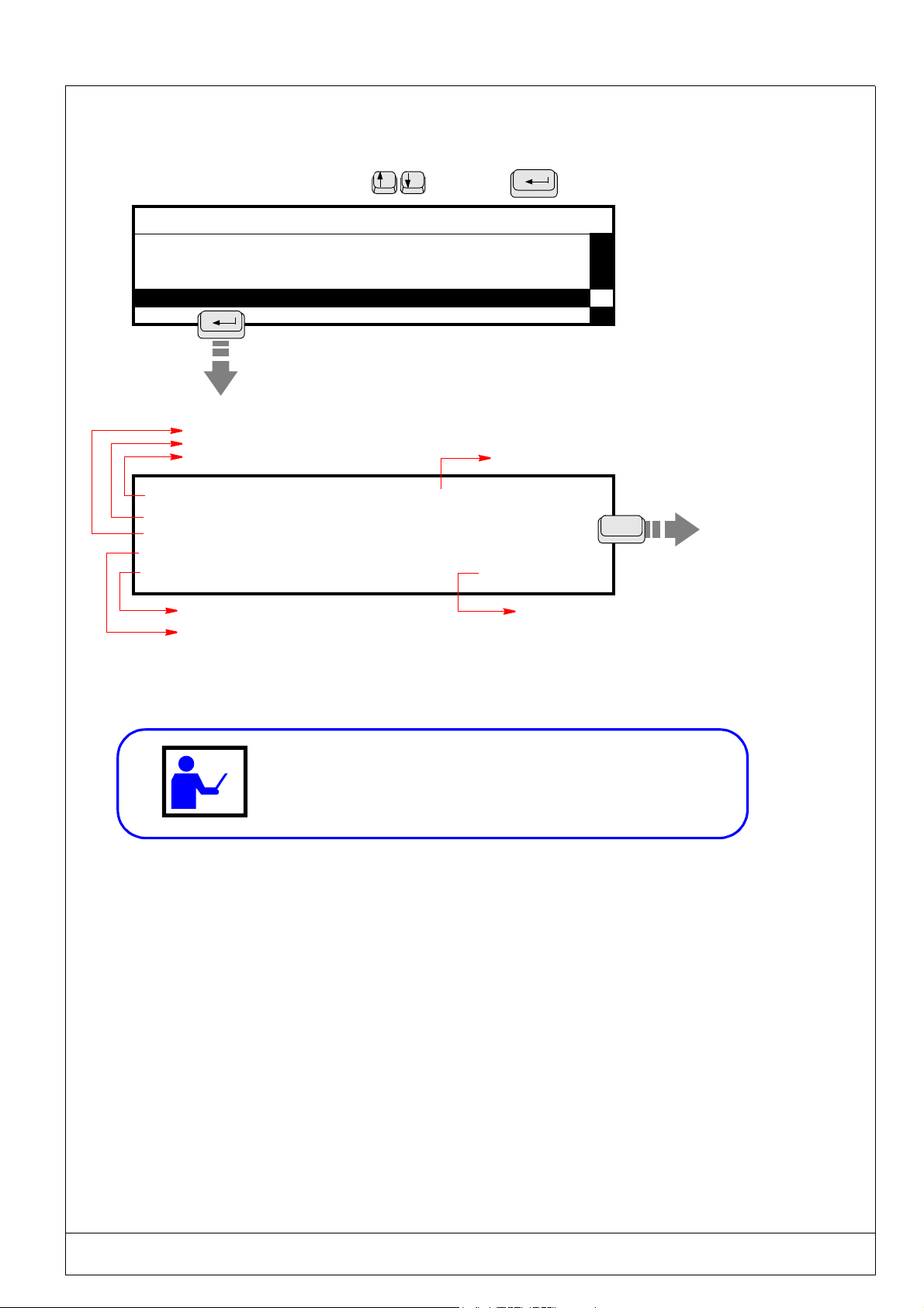
(Ref.90703-MDIS4314/0601C0-chap024314.fm.doc) PRO-PEN
2.9.10. Machine characteristics
This function will display all information about the M3000 and the command board.
Select this parameter using the arrow keys. Press
- CONFIGURATION -
Language
List of available fonts
List of available fonts
Machine characteristics
Vertical M3000 movement (Y axis)
Horizontal M3000 movement (X axis)
Command board serial number
Serial No. : 03-02-004258 Head
Max X Path
Max Y Path
::60.00
40.00
[ mm ]
[ mm ]
Pneumatic marking tool
Three axes
Option not available
Marking tool used
: N
100.0 % Free
to validate.
Machine type
:M3000PN
Esc
Percentage of memory available
in the command board
If you have any queries concerning your equipment, contact your
distributor, giving all the information shown on this screen.
USING THE MARKING PROGRAM WITH EXTERNAL KEYBOARD IN "PROGRAMMING" MODE 2 - 57
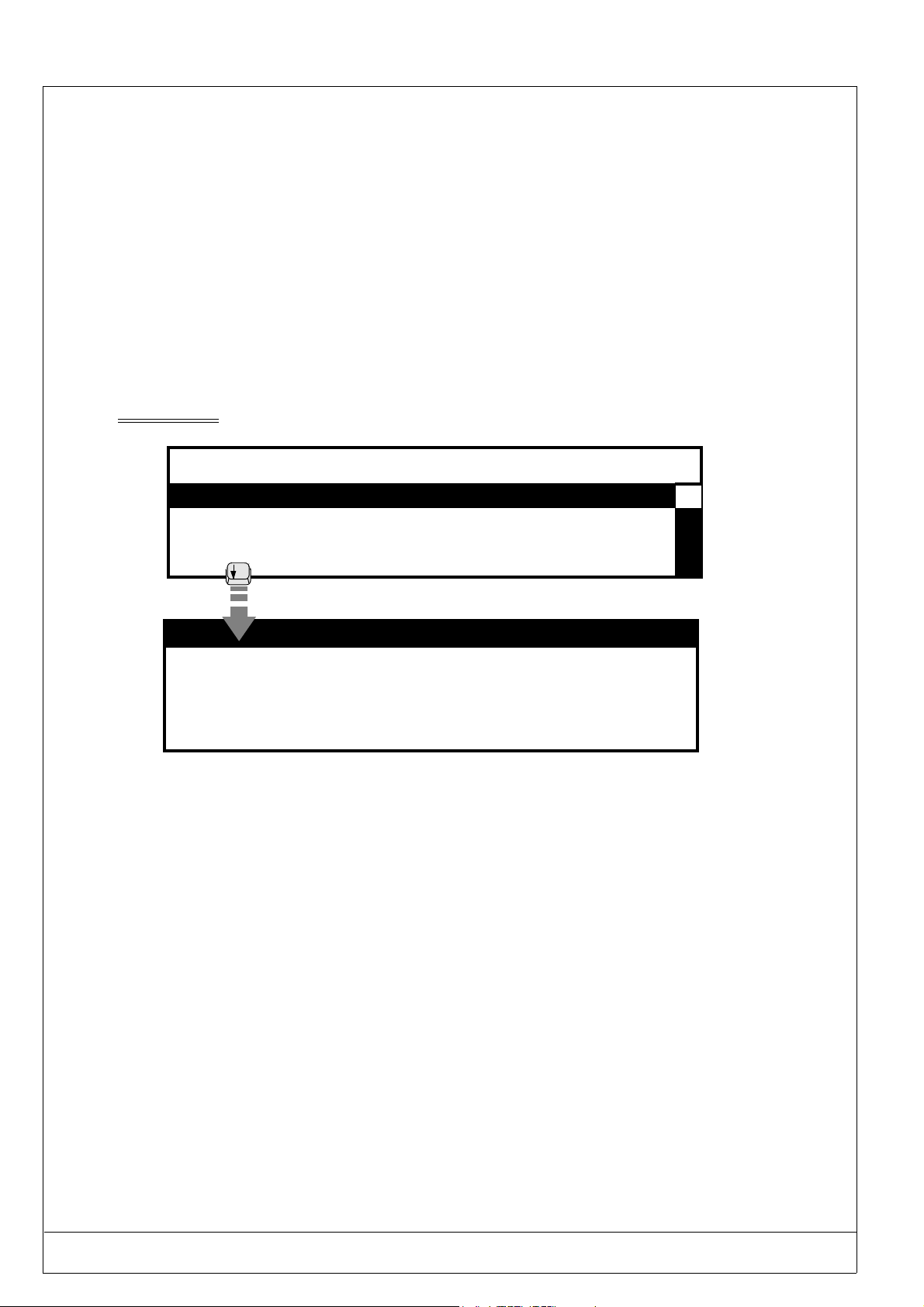
PRO-PEN (Ref.90703-MDIS4314/0601C0-chap024314.fm.doc)
2.9.11. Dialogue Configuration
This function is optional and only accessible if ordered when ordering the marking equipment.
This function will permit you to configure the messages diplayed on the screen during the operations related to the marking as well as the corresponding codes sent from the machine.
This function has two entry screens.
Pre-determined texts for the messages:
. Waiting for data reception: the machine will send the
. Correct data reception: the machine will send the
. Reception error: the machine will send the
Tcode back.
U code back,
Vcode back,
• The first screen
will permit you to configure the messages displayed while waiting for data reception.
- CONFIGURATION -
Dialogue Configuration
DISPLAY CONFIGURATION
P1 : WAITING FOR RECEPTION
P2 : MARKING
P3 : ERROR !! WAITING FOR NEW ENTRY
Free recordings : 100
P1 : Message displayed when the program reaches a block containing the CB instructuion. The message wil remain displayed as long as the data is not received.
P2 : Message displayed when the data has been correctly received and will remain displayed throughout the marking.
P3 : Message displayed if a checksum erro has been detected or if the data received is identical to the P7 zone. (see se-
cond screen on the next page).
Free recordings: the value will correspond to the number of recordings still available in the machine for the historical file.
2 - 58 USING THE MARKING PROGRAM WITH EXTERNAL KEYBOARD IN "PROGRAMMING" MODE
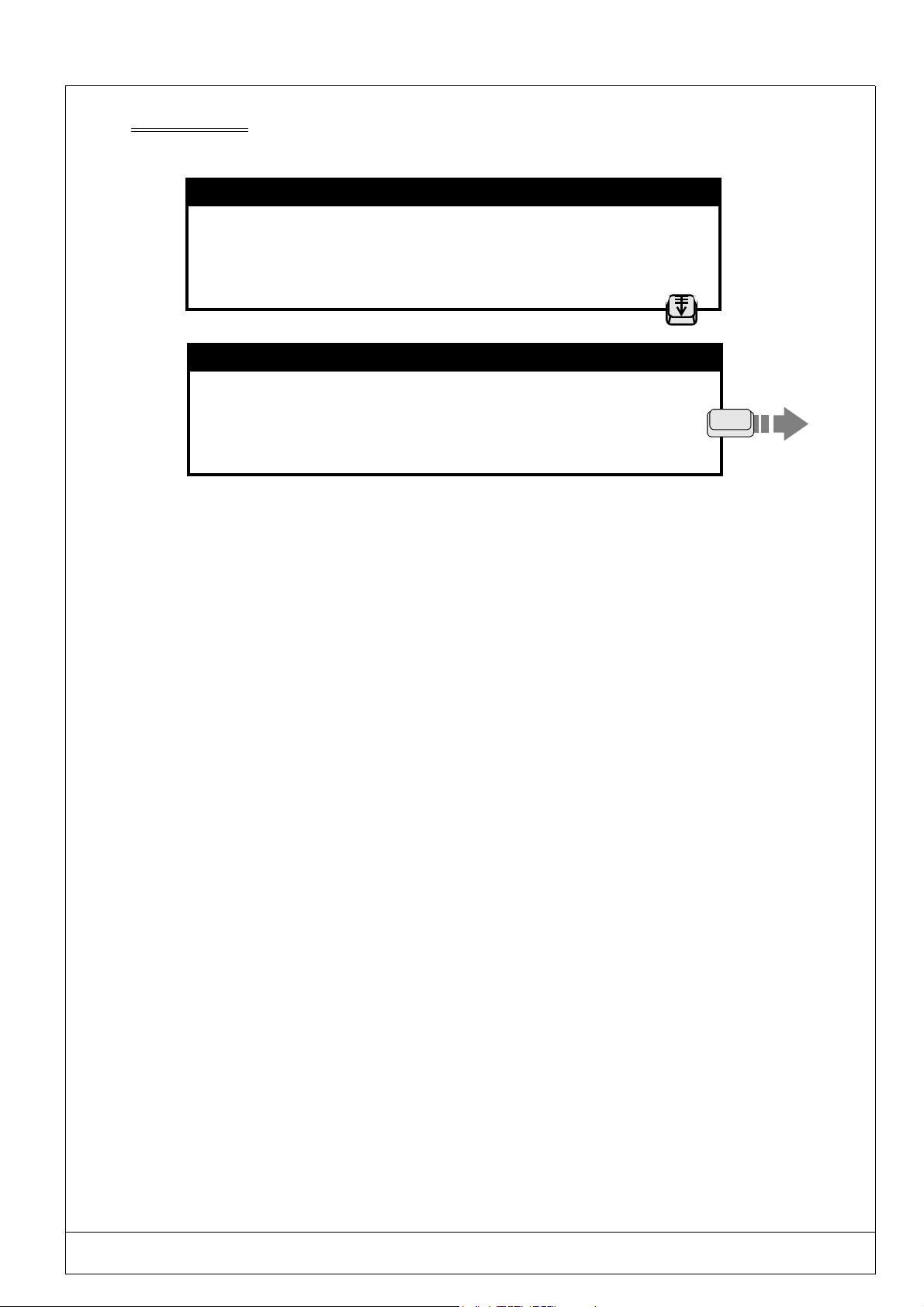
(Ref.90703-MDIS4314/0601C0-chap024314.fm.doc) PRO-PEN
The second screen will permit you to configure the responses sent back by the machine via the RS232 connector. Press
"Page Down" when the preceeding screen is displayed.
DISPLAY CONFIGURATION
P1 : WAITING FOR RECEPTION
P2 : MARKING
P3 : ERROR !! WAITING FOR NEW ENTRY
Free recordings: 100
Page Down
DIALOGUE CONFIGURATION
P4 : U
P6 : T
Communication
Checksum
Input : 0
P5 : V
P7 :
S0
ESC
S1
P4 : The contents of the P4 zone will be transmitted by the RS232 when the machine is waiting for the reception of data .
P5 : The contents of the P5 zone will be transmitted when the machine has correctly received the data.
P6 : The contents of the P5 zone will be transmitted when the checksum is incorrect or if the data received is equal to
that of the P7 zone
P7 : If the contents of this zone corresponds to the data received the machine will display the P3 message and remain
waiting for the receptin of new data. This zone can receive 14 characters.
Communication : If this button is not activated, no communication will be possible by the RS232 connector except for
data reception and transmission of the contents of the P4 – P5 – P6 zones.
Checksum : If this button is activated the machine will compare the checksum recieved with that calculated by itself
using the data received.
Input : Not valid.
S0 : Not valid.
S1 : Not valid.
Press ESC to exit this screen.
USING THE MARKING PROGRAM WITH EXTERNAL KEYBOARD IN "PROGRAMMING" MODE 2 - 59
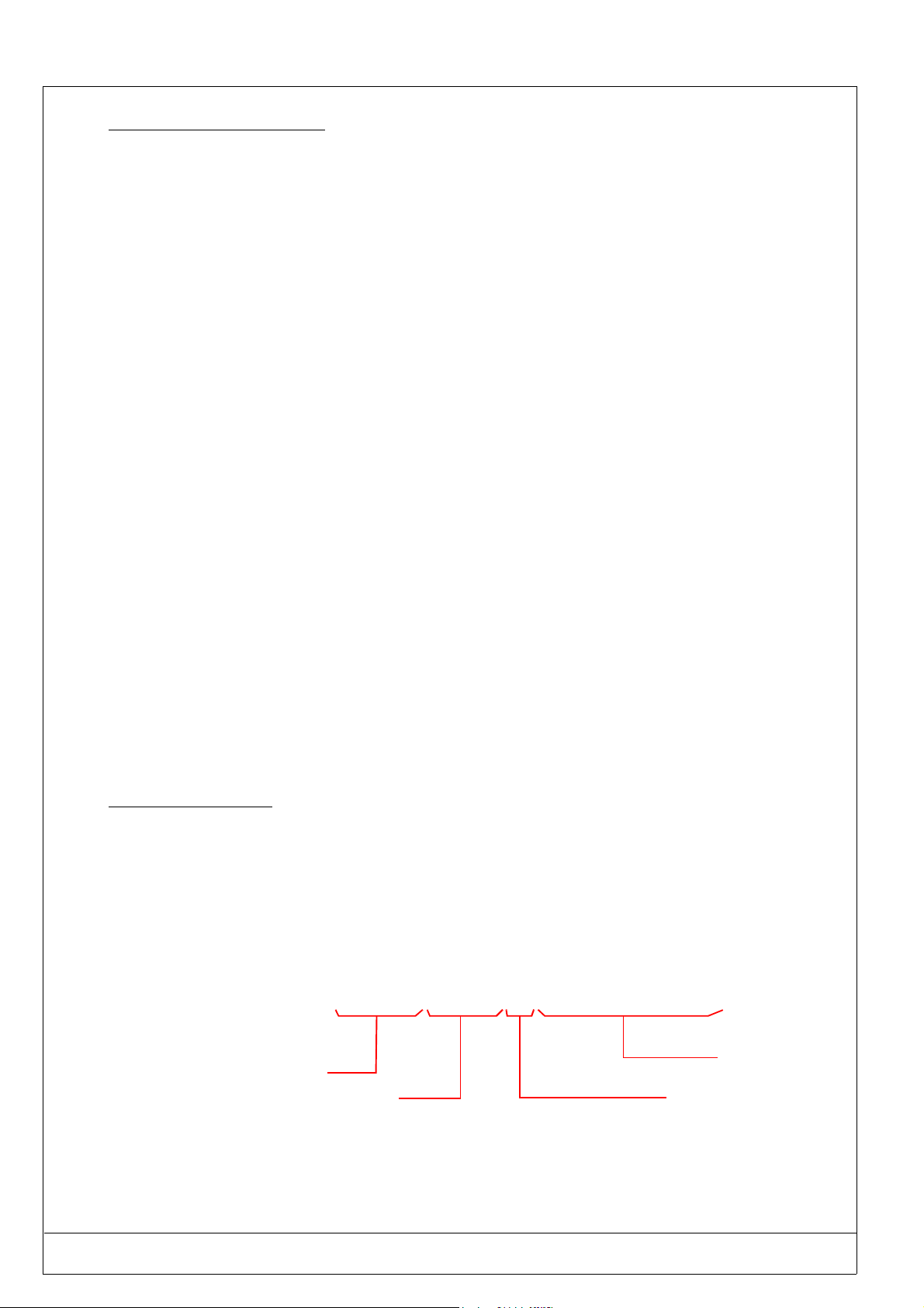
PRO-PEN (Ref.90703-MDIS4314/0601C0-chap024314.fm.doc)
2.9.11.1 - Checksum Algorithm
The checksum will be added to the end of the message. It is represented by 2 conscecutive characters (0 - F, hexadecimal).
The originator will calculate the checksum with the useful data from the transmitted message.
The receiver will also calculate the checksum with the useful transmitted data and then compare this new checksum with
the one received.
. If the 2 checksums are identical, the message’s data will be valid. The receiver will reply by returning the con-
tents of the P5 zone by the RS232 connector.
. If the 2 checksums are different, the receiver will send back the message contained in the P6 zone by default.
The calculation of the checksum can be made by making an "or exclusive" (XOR) between the characters contained in
the useful part of the message.
. Emission Checksum = "character1 emitted" XOR "character2 emitted" XOR ..…. "Character n emitted".
The result is a number of 8 bytes (0 - 255) coded on 2 characters (00 - FF) so as to be transmissable on the line.
. Reception Checksum = "character1 received" XOR "character2 received" XOR …... "Character n received".
• Examples 1
The "ABCD" message:
Checksum = 65 XOR 66 XOR 67 XOR 68
= 4 hexadecimal
The originator will send the"ABCD04" message
• Examples 2
The "12345"message:
Checksum = 49 XOR 50 XOR 51 XOR 52 XOR 53
= 49 decimal
= 31 hexadecimal
The originator will send the "1234531"message
2.9.11.2 - Historical file
The historical file can contain a maximum of 100 recordings. When it is full a message will be displayed on the screen
and suggest two possiblilities:
• Continue the marking without saving the data received,
• Overwrite the oldest recording in the historical file.
The historical file is not visible on the screen of the machine but it can be recuperated with the RS232 connector using
the <ESC>RB 0<CR> command.
The historical file will be recuperated in the following format:
DMMYYYY/HHMMSS/CB/Contents of the variable
Day
Month
Ye ar
Hours
Minutes
Seconds
coming form a block
containing the CB instruction
Données mémorisées
dans la variable
To reinitialize this file, use the <ESC>RB 1<CR>command.
The data will be definitely lost.
2 - 60 USING THE MARKING PROGRAM WITH EXTERNAL KEYBOARD IN "PROGRAMMING" MODE

(Ref.90703-MDIS4314/0601C0-chap024314.fm.doc) PRO-PEN
2.10) Function keys
The function keys will give you access to certain options in the program, such as marking simulation, positioning the
marking tool, adding a block, etc...
2.10.1. F2 : Access to the second entry screen
This function applies to menus containing several entry screens. Press F2 to access the second
entry screen. The menus affected by it are :
• File entry
• Block assistant
*
X : 0.00 Y : 0.00 [mm]
Text :
Size : 0.50 [mm] Stroke : 2
Linear Angular Radial
F2
Access to the
second entry
screen
Block : 1
8 / 81
Normal Mirrored Inverted Reflected
Centering
Compression : 1.00
Pause Font N°: 0
Spacing: 1.00
Inclination : 0.00
:
:
H
Esc
Block : 1/1
Esc
4/4
USING THE MARKING PROGRAM WITH EXTERNAL KEYBOARD IN "PROGRAMMING" MODE 2 - 61

PRO-PEN (Ref.90703-MDIS4314/0601C0-chap024314.fm.doc)
2.10.2. F3 : Positioning the marking tool
This "dynamic adjustment" function will permit you to move the marking tool above the surface to be marked so as to
determine the start coordinates for marking.
H
*
Esc
Block : 1/1
X :5.00 Y : 5.00 [mm]
Text : Marking machine
Size : 2.00 [mm] Stroke : 2
Linear Angular Radial
F3
Access to the
second entry
screen
Esc
Manual positioning of X / Y
X : 5.00
Y : 5.00
Positioning... Press a key
Press any key : The marking tool will position itself at the coordinates shown for
the current marking block.
H
"Start marking"
coordinates for
the current block
Manual positioning of X / Y
X : 12.70 Y : 15.80
Press enter to validate
Use the four arrow keys to adjust the X and Y values
Adjust the position of the marking tool using the four arrow
keys.
The movement value is 0.10 mm, for X or Y.
When the marking tool is correctly positioned, press
to validate.
The new coordinates will appear on the screen.
2 - 62 USING THE MARKING PROGRAM WITH EXTERNAL KEYBOARD IN "PROGRAMMING" MODE

(Ref.90703-MDIS4314/0601C0-chap024314.fm.doc) PRO-PEN
2.10.3. F4 : Simulate marking of the current block
This function will permit you to simulate the marking of the current block, without having to go through
the “Marking” menu.
H
Esc
*
X : 5.00 Y : 10.00 [mm]
Text : PROPEN
Size : 2.00
Linear
F4
Marking in progress. . .
S I M U L A T I O N
Block 3 start position
Pause ... <Space> to continue
Enter > Suspend marking
The simulation process will be executed as described in chapter 2.6.4. but only for a single block .
When the simulation is completed, the program will return to the marking file.
[mm] Stroke : 2
Angular Radial
:
Block : 3/6
Esc
USING THE MARKING PROGRAM WITH EXTERNAL KEYBOARD IN "PROGRAMMING" MODE 2 - 63

PRO-PEN (Ref.90703-MDIS4314/0601C0-chap024314.fm.doc)
2.10.4. F5 : Add a block at the end of a file
This function will permit you to add “empty” marking blocks to an existing file.
The numbering will be automatically updated.
*
X : 5.00 Y : 5.00 [mm]
Text : Marking machine
Size : 2.00 [mm] Stroke: 2
Linear Angular Radial
F5
*
X : 0.00 Y : 0.00 [mm]
Text :
Size : 0.50 [mm] Stroke : 2
Linear Angular Radial
Block : 3/3
Block : 4/4
2.10.5. F6 : Delete the current block
This function will permit you to delete a marking block. Select the block you wish to delete and press “F6”.
F6
*
X : 5.00 Y : 5.00 [mm]
Text : Marking machine
Size : 2.00 [mm] Stroke : 2
Linear Angular Radial
For safety reasons, the program will require confirmation before deleting a marking block :
DELETE BLOCK 3
Confirmation Esc/y/n: _
Block :3/3
Enter “y” : the program will delete the block and update the numbering.
2 - 64 USING THE MARKING PROGRAM WITH EXTERNAL KEYBOARD IN "PROGRAMMING" MODE

(Ref.90703-MDIS4314/0601C0-chap024314.fm.doc) PRO-PEN
2.10.6. F7 : Copy the current block
This function will permit you to add an identical block to the selected block. The program will reproduce and insert this
new block after the selected one.
*
X : 5.00 Y : 5.00 [mm]
Text : Marking machine
Size : 2.00 [mm] Stroke : 2
Linear Angular Radial
F7
*
X :5.00 Y : 5.00 [mm]
Text : Marking machine
Size : 2.00 [mm] Stroke : 2
Linear Angular Radial
The program will also proceed to automatically update the numbering.
2.10.7. F8 : Insert an empty block
This function will permit you to insert an "empty" block above a selected block.
Block : 3/6
Block : 4/7
*
X : 0.00 Y : 0.00 [mm]
Text :
Size : 0.50 [mm] Stroke :
Linear Angular Radial
F8
*
X : 5.00 Y : 5.00 [mm]
Text : Marking machine
Size : 2.00 [mm] Stroke : 2
Linear Angular Radial
Numbering will be automatically updated.
Example: insert a block in front of block 3. The file will then be made up of 7 blocks.
1/7-->1/8;2/7-->2/8; Insert a block 3/8; 3/7-->4/8,4/7-->5/8;5/7-->6/8;6/7-->7/8;7/7-->8/8
Block : 4/9
Block : 4/8
USING THE MARKING PROGRAM WITH EXTERNAL KEYBOARD IN "PROGRAMMING" MODE 2 - 65

PRO-PEN (Ref.90703-MDIS4314/0601C0-chap024314.fm.doc)
2.10.8. F9 : Assistant
This function will permit you to adapt the dimensions of a text to fit the size of a predetermined marking zone, or, alternatively, to adapt the size of the marking zone to fit the text.
This function is only available in the "Linear marking" mode, and is accessed from the "Marking" menu.
Follow these instructions to carry out a marking: :
Position the M3000 against the part to be marked.
Select the "File " menu and validate with the ENTER key.
H
Create a new marking file pressing on
+
*
X : 0.00 Y : 0.00 [mm]
Text :
Size : 0.50 [mm] Stroke : 2
Linear Angle Radidal
F9
- ASSISTANT -
Text :
Enter the text to be marked. Press <Enter>
then press on F9.
F5
Block : 1/1
Block : 1/1
Enter the text to be marked, then validate pressing on "ENTER".
- ASSISTANT -
Text : PRO-PEN
Enter the text to be marked. Press <Enter>
2 - 66 USING THE MARKING PROGRAM WITH EXTERNAL KEYBOARD IN "PROGRAMMING" MODE
Block : 1/1

(Ref.90703-MDIS4314/0601C0-chap024314.fm.doc) PRO-PEN
Press any keyboard key. The marking tool wil move to the marking block’s X-Y coordinates.
In this example : X = 0 et Y = 0.
X : 0.00
Positioning... Press a key
Move the marking tool to the bottom left of the zone in which you wish to mark using the
When the desired position has been reached, validate with
X : 14.70
Press <Enter> to validate
Press the
arrow keys to move the marking tool to the top right corner of the zone you intend to mark.
Y : 0.00
Y : 20.00
arrow keys.
X1 and Y1 coordinates
When the desired position has been reached, validate with
X : 49.60
Press <Enter> to validate
Y : 15.40
X2 and Y2 coordinates
USING THE MARKING PROGRAM WITH EXTERNAL KEYBOARD IN "PROGRAMMING" MODE 2 - 67

PRO-PEN (Ref.90703-MDIS4314/0601C0-chap024314.fm.doc)
there are three problems you may encounter on the X-Y coordiantes you have entered ;.
Case n°1
The coordinates selected for your marking zone do not designate a marking window :
• the second point (X2) must be top the right of the first point (X1) (X1<X2)
• the second point Y2 must be above the first point (Y1) (Y2<Y1)
Invalid coordinates:
X inferior left> X superior right
Y inferior left < Y superior right
Press <Enter>
Case n°2
The designated zopne is too high in relation to its width :
• increase the width of the marking zone, or
• delete some of the text
The marking zone is too small
- enlarge the marking zone
- reduce the length of the text in the marking
block
Press <Enter>
Case n°3
The program will automatically calculate the character size and level of compression to ensure that
the text will fit the marking zone.
010 Block 2/2
-ASSISTANT-
Character size: 4.60
Text length : 3 4.90
Compression rate : 1.10 Press Enter
010
Block : 1/1
X : 14.7 Y : 20.0 [mm]
Text : PRO-PEN
Size : 0.50 [mm] Stroke : 2
Rate
1.1
Linear Angular Radial
Character compression rate
2 - 68 USING THE MARKING PROGRAM WITH EXTERNAL KEYBOARD IN "PROGRAMMING" MODE

(Ref.90703-MDIS4314/0601C0-chap024314.fm.doc) PRO-PEN
2.10.9. F10 : Mark a file
This function key provides a shortcut to the "Marking" menu, and will permit the current file to be marked one time, "n"
times or infinitely. This function may also be used to simulate a file.
*
X : 5.00 Y : 5.00 [mm]
Text : Marking machine
Size : 2.00 [mm] Stroke : 2
Linear Angular Radial
M A R K I N G : TEST
1 time
n times
infinite
File Simulation
:
[ 1
:
:
] times
Block : 4/4
F10
See paragraph 2.6)
"Marking menu".
.
2.10.10. F11 : Save the current file
This function applies to the "Marking" menu and should always be used when creating or modifying files.
Case 1 : You have created a marking file and are saving it for the first time :
The number given to
the file will appear in
this zone.
*
X : 5.00 Y : 5.00 [mm]
Text : Marking machine
Size : 2.00 [mm] Trait : 2
Linear Angular Radial
*
Enter file number [0 999] : 010
File comments
Test
010
Enter file number [0 999] : 010
File comments
Test
File saved Exit : [ Esc ]
Esc
Block : 4/4
F11
194 Bytes
Size of the saved
file.
USING THE MARKING PROGRAM WITH EXTERNAL KEYBOARD IN "PROGRAMMING" MODE 2 - 69

PRO-PEN (Ref.90703-MDIS4314/0601C0-chap024314.fm.doc)
.
Case 2 : After an existing file has been modified, it may be saved under its original name or a new name :
Number of the modified file
015*
Enter file number [0 999] :015
File comments
Test
Enter Yes /No. If it is "y" :
015
Enter file number [0 999] : 015
File comments
Test
File saved Exit : [ Esc ]
015
Replace file ? (y / n) : _
Existing file !
194 Bytes
2 - 70 USING THE MARKING PROGRAM WITH EXTERNAL KEYBOARD IN "PROGRAMMING" MODE
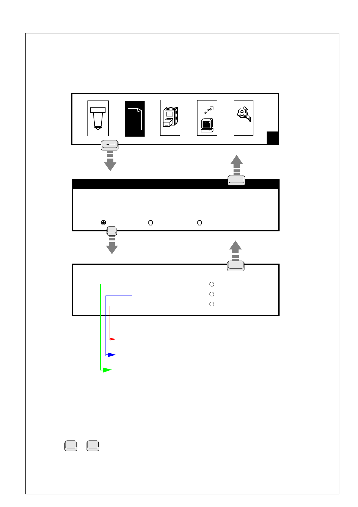
(Ref.90703-MDIS4314/0601C0-chap024314.fm.doc) PRO-PEN
2.10.11. F12 : Marking priorities
This function will permit you to adapt the quaility of the marking to the marking requirements by determining a "Priority".
It is necessary to keep in mind that very high quality marking should be executed at a slow speed, while faster marking
speed will lower its quality .
H
TEST2 Block : 1/1
X : 5.00 Y : 5.00 [mm]
Text : Marking machine
Size : 2.00 [mm] Stroke: 2
Linear Angular Radial
F12
Press the space bar to select the marking priority.
TEST2
Priority Marking quality
Intermediate
Cycle run time
Average quality marking
Very high speed : short cycle
Good quality marking
Rapid speed : average cycle
Very high quality marking
Slow speed : long cycle
Esc
Esc
Select using the space bar
2.10.12. [Ctrl] + [Alt] + [+/-]
This function will permit you to adjust the contrast of the LCD screen.
Ctrl
USING THE MARKING PROGRAM WITH EXTERNAL KEYBOARD IN "PROGRAMMING" MODE 2 - 71
+
Alt
Maintain these two keys pressed down, and press several times on the "+" or "-"
keys:
+ = will darken the screen
- will lighten the screen

PRO-PEN (Ref.90703-MDIS4314/0601C0-chap024314.fm.doc)
2.11) Data reception using the RS232
The @CB(......)@ instruction used in a text block will permit you to introduce a chain of characters received through the
RS232 connection or from the keyboard port.
The chain of characters received will be stored in a specific variable in the @CB(......)@ instruction.
2.11.1. Syntax used
@CB(firstchar,endchar,mode,saving,V,batch)@
2.11.1.1 - Definition
firstchar : Position number in the chain of characters received from which the text to be stored should be taken
into account to save it in the "V" variable.
Whole number value beween 0 and the length of the chaine of characters received.
endchar : Position number in the chain of characters received up to which the text to be stored should be taken
into account to save in the "V" variable.
Whole number value beween 0 and the length of the chain of characters received.
mode : 0 : data is received by the serial port.
2 : data is received by the PC’s keyboard port.
saving : Specifies whether data received in the variable will be saved in the historical file.
0 : The data will NOT be saved.
1 : The data will be saved (100 files max).
V : number of the variable in which the text should be saved, between V0 and V9.
batch : number of markings to be made with this variables programming before entering a new program.
1 : Data reception will be necessary at each marking.
0 : Data reception necessary only once, at the time of the first marking (even in the case of multiple
markings of the file).
Remark : After the machine has been switched off, after a reset or if the file has been exited by pressing the ESC key, a new data reception will be necessary.
-1 : The data reception will only be carried out if the operator requests it, either by:
. pressing the keyboard keys of the machine (CTRL + ALT + G),
. activation of an input,
. sending the order <ESC>CI<CR> via the RS232 connector.
2 - 72 USING THE MARKING PROGRAM WITH EXTERNAL KEYBOARD IN "PROGRAMMING" MODE
(Ref.90703-MDIS4314/0601C0-chap024314.fm.doc) PRO-PEN
2.11.1.2 - Examples
Example 1: @CB(1,4,0,0,2,1)@
• When the file is being executed, the "waiting for reception" message will be displayed until the text is received on the
RS232 port.
• The received text will be saved in the n°2 variable (V2).
The operator should transmit the 0123456789 text. However only the chain between the n°1 and n° 4 characters will be
saved in V2. Therefore V2 = 0123.
• The text "MARKING" will be displayed on the screen throughout the marking until the next reception request (or end
of marking cycle).
• A acquisition request will be made for each marking of the file, because in this example the batch is equal to 1.
Example 2 : @CB(0,0,0,1,3,-1)@
• Data reception is only necessary if the operator requests it, either by :
. pressing simultaneously on the keys "Ctrl + Alt + G",
. sending the order <ESC>CI<CR> via the RS232 connector,
. activation of an input defined in the menu "Dialogue configuration".
• The text received by the RS232 connector is saved in the n°3 variable. The complete chain is saved because the value
of "firstchar and endchar" is 0.
• The complete chain is saved in the historical file because the value of the parameter "saving" is 1.
2.11.2. Utilization in a marking file
It is possible within the same file to move to several blocks containing the @CB@ instruction.
The marking of the contents of the correponding variables (enter @Vi@) can be done either immediately after the entry
or later.
Example 1 : Two blocks containing the @CB@ instruction follow each other :
Two di fferent
Block 1 : @CB....V1....@
Block 2 : @CB....V2....@
Block 3 : @V1@
Block 4 : @V2@
Marking of the contents of these two reception variables will be done after the second entry.
Example 2 : Two blocks containing the @CB@ insstruction do not follow each other :
and successive entries are necessary:
Two different but
not successive entries are necessary :
Block 1 : @CB...V1....@
Block 2 : @V1@
Block 3 : @CB...V2....@
Block 4 : @V2@
Marking of the contents of these 2 reception variables will be done after each of these two entries.
In the case of this type of operation it is necessary that the value of the batch be
identical for the @CB@ instructions. Otherwise the value of the first command
will be given by default.
USING THE MARKING PROGRAM WITH EXTERNAL KEYBOARD IN "PROGRAMMING" MODE 2 - 73
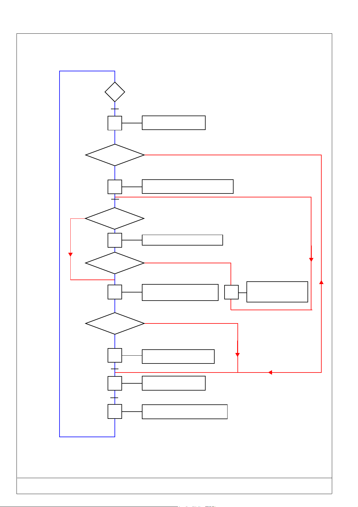
PRO-PEN (Ref.90703-MDIS4314/0601C0-chap024314.fm.doc)
2.11.3. Algorithm for use of the CB instruction by itself
0
Press the start marking button
NO
1
Number of
markings = number
of batches
YES
2
ASCII 13 code received
Activated
checksum control?
YES
3
CS received
= CS emitted?
YES
4
Prepare the text blocks
NO
Text waiting on port - "P1" displayed
U<CR>code emitted
Checksum calculation from receipt
NO
"Vi"chain saved - "P2" displayed
V<CR> code emitted
T<CR> code emitted
5
"P3" displayed
Text waiting on port RS232
Activated pause?
YES
6
Start marking activated
7
End of marking cycle
8
NO
Waiting for start marking order
07<CR> contact or sequence
Preparing the next blocks
Number of markings incremented
2 - 74 USING THE MARKING PROGRAM WITH EXTERNAL KEYBOARD IN "PROGRAMMING" MODE

(Ref.90703-MDIS4314/0601C0-chap024314.fm.doc) PRO-PEN
2.11.3.1 - Creation of a marking file
H
ESC
Block : 1/3
X : 10.00 Y : 10.00 [mm]
Text : TEST
Size : 3.00 [mm] Stroke : 2
Linear Angular Radial
F5
Marking the text "TEST"
with coordinates X = 10 mm and Y = 10 mm
X : 0.00 Y : 0.00 [mm]
Text :
@CB(3,12,0fdf,0,0,1)@
Size : 0.50 [mm] Stroke : 2
Linear Angular Radial
F5
Reception of text : AZERTYUIOPQSDFGHJKLM <CR>
The ERTYUIOPQS text is saved in the V0 variable
X : 5.00 Y : 22.00 [mm]
Text :
@V0@
Size : 4.20 [mm] Stroke : 2
Linear Angular Radial
Block : 2/3
Block : 3/3
Marking obtained : ERTYUIOPQS
USING THE MARKING PROGRAM WITH EXTERNAL KEYBOARD IN "PROGRAMMING" MODE 2 - 75
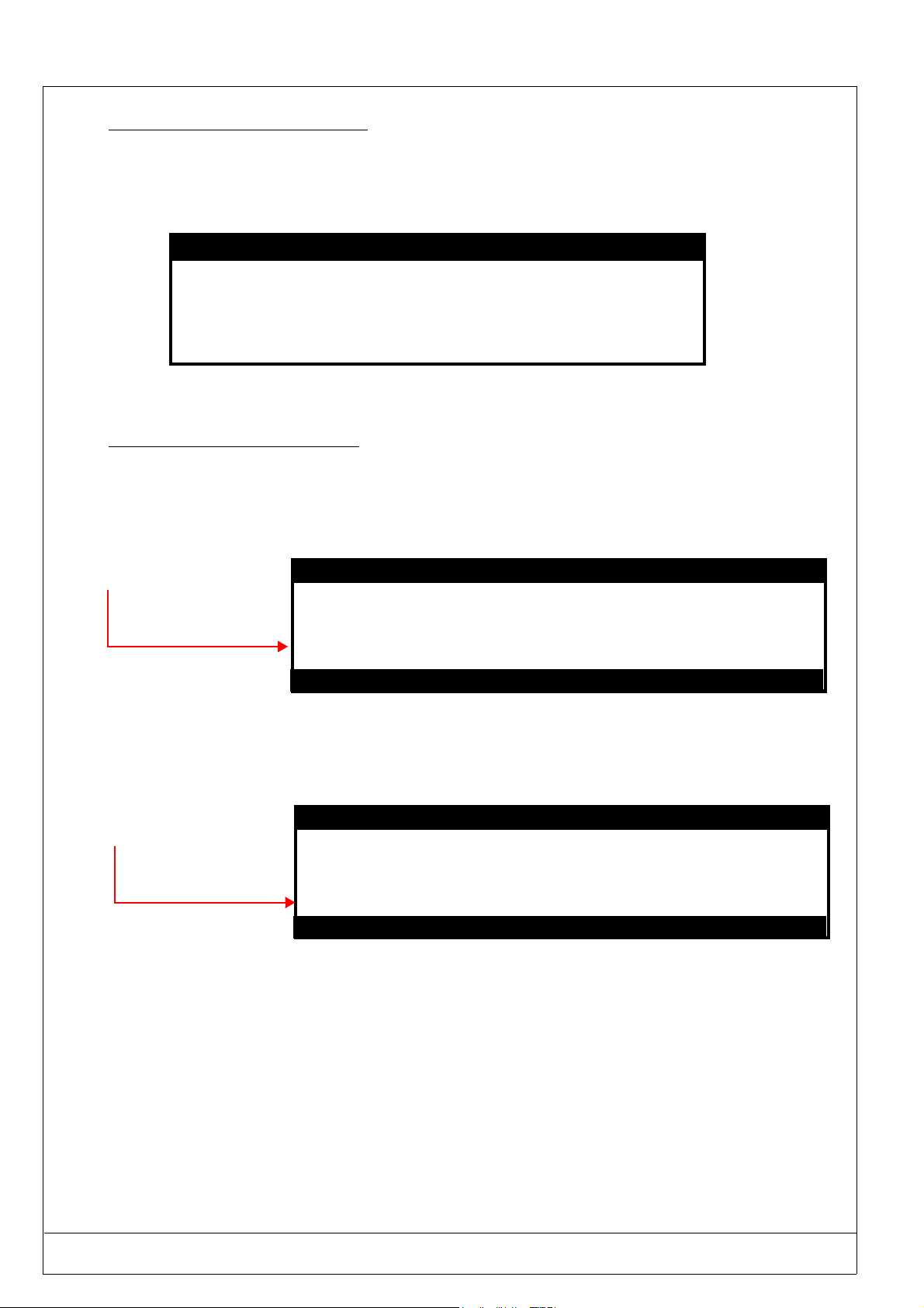
PRO-PEN (Ref.90703-MDIS4314/0601C0-chap024314.fm.doc)
2.11.3.2 - Specification of the P2 zone
It is possible to introduce a keyword into the P2 zone.
This could be, for example, the number of the variable in which the received chain of characters is saved.
DISPLAY CONFIGURATION
P1 : WAITING FOR RECEPTION
P2 : MARKING : @V0@
P3 : ERROR !! WAITING FOR NEW ENTRY
Free recordings : 100
2.11.3.3 - Cycle operating procedure
• Launching the marking.
• Marking of the text in the first block : TEST.
• Machine waiting for reception of data from the RS232 port.
During this waiting period, the contents of the
"P1" message will be
displayed on the screen
• Data reception by the machine from the RS232.
• Data saved in the V0 variable, specified on the CB instruction line.
• End of acquisition and marking of the chain saved in the "V0" variable : ERTYUIOPQS
The following message
will be displayed at the
end of the marking of the
file:
WAITING FOR RECEPTION
Marking of : ERTYUIOPQS
If the pause function is activated for the CB block, the P2 message will remain displayed on the screen until:
. the space bar is pressed,
. the start marking contact of the communication interface terminal is closed .
This allows control of the variable’s content before marking it.
2 - 76 USING THE MARKING PROGRAM WITH EXTERNAL KEYBOARD IN "PROGRAMMING" MODE

(Ref.90703-MDIS4314/0601C0-chap024314.fm.doc) PRO-PEN
2.12) Available character fonts and logos
2.12.1. Chart of available fonts
FONT
N°
000
001
003
098
099
ARTICLE
CODE
T2960001 XSTD200
T2960002 XPTS200
T2960004 X57C200
T2960098 LOGOCE
T2960099 LGOCE200
NAME OF FILE
IN SOFTWARE
pneumatic machines : Fonts N° 1 - 3 and 98/99 are included as part of the standard config-
uration
electromagnetic machines : Fonts N° 1 - 3 and 98 are included as part of the standard con-
figuration
(The fonts N°0 and 99 do not work with electromagnetic machines)
AVAILABLE FONTS
DESCRIPTION TYPE PNEUMATIC
Standard font of very high definition,
ing practically all DOS n° 850 Multilingual
contain-
Continuous
stroke
(Latin 1) characters
High legibility characters, containing practi-
separated dots
cally all DOS n° 850 Multilingual (Latin 1)
characters
Font conforming to the standard SNECMA
DT05-89
Separated dots
Standard 5 x 7
«CE» standard logo Separated dots
«CE» standard logo Continuous
stroke
AVAILABILITY
MACHINES
STANDARD
STANDARD STANDARD
STANDARD STANDARD
STANDARD STANDARD
STANDARD
ELECTROMAGNETIC
MACHINES
2.12.2. Using special characters
You will find in the follwiong pages the codes to be used to enter and visualize on the screen the characters that do not
exist on the keyboard so that they may also be marked.
For example, to obtain the "¿" character :
• Lock the "Num. lock" key,
• Maintain the "ALT" key pressed down
• Enter the "168" code on the number keyboard
• Release the "ALT" key
USING THE MARKING PROGRAM WITH EXTERNAL KEYBOARD IN "PROGRAMMING" MODE 2 - 77

PRO-PEN (Ref.90703-MDIS4314/0601C0-chap024314.fm.doc)
2.12.3. Font N°000 - continuous stroke
ASCII ANSI CAR ASCII ANSI CAR ASCII ANSI CAR ASCII ANSI CAR
32 032
33 033
34 034
35 035
36 036
37 037
38 038
39 039
40 040
41 041
42 042
43 043
44 044
45 045
46 046
47 047
48 048
49 049
50 050
51 051
52 052
53 053
54 054
55 055
56 056
57 057
58 058
59 059
60 060
61 061
62 062
63 063
64 064
65 065
66 066
67 067
68 068
69 069
70 070
71 071
72 072
73 073
74 074
75 075
76 076
77 077
78 078
79 079
80 080
81 081
82 082
83 083
84 084
85 085
86 086
87 087
88 088
89 089
90 090
ESPACE
!
"
#
$
%
&
'
(
)
*
+
,
-
.
/
0
1
2
3
4
5
6
7
8
9
:
;
<
=
>
?
@
A
B
C
D
E
F
G
H
I
J
K
L
M
N
O
P
Q
R
S
T
U
V
W
X
Y
Z
91 091
92 092
93 093
94 094
95 095
96 096
97 097
98 098
99 099
100 0100
101 0101
102 0102
103 0103
104 0104
105 0105
106 0106
107 0107
108 0108
109 0109
110 0110
111 0111
112 0112
113 0113
114 0114
115 0115
116 0116
117 0117
118 0118
119 0119
120 0120
121 0121
122 0122
123 0123
124 0124
125 0125
126 0126
127 0127
128 0199
129 0252
130 0233
131 0226
132 0228
133 0224
134 0229
135 0231
136 0234
137 0235
138 0232
139 0239
140 0238
141 0236
142 0196
143 0197
144 0201
145 0230
146 0198
147 0244
148 0246
149 0242
[
\
]
^
_
`
a
b
c
d
e
f
g
h
i
j
k
l
m
n
o
p
q
r
s
t
u
v
w
x
y
z
{
|
}
~
∆∆∆∆
Ç
ü
é
â
ä
à
å
ç
ê
ë
è
ï
î
ì
Ä
Å
É
æ
Æ
ô
ö
ò
150 0251
151 0249
152 0255
153 0214
154 0220
155 0248
156 0163
157 0216
158 0215
159 0131
160 0225
161 0237
162 0243
163 0250
164 0241
165 0209
166 0170
167 0186
168 0191
169 0174
170 0172
171 0189
172 0188
173 0161
174 0171
175 0187
179 0166
181 0193
182 0194
183 0192
184 0169
189 0162
190 0165
198 0227
199 0195
203 0153
207 0164
208 0240
209 0208
210 0202
211 0203
212 0200
213 0185
214 0205
215 0206
216 0207
217 0166
222 0204
224 0211
225 0223
226 0212
227 0210
228 0245
229 0213
230 0181
231 0254
û
ù
ÿ
Ö
Ü
ø
£
Ø
×
ƒ
á
í
ó
ú
ñ
Ñ
ª
º
¿
®
¬
½
¼
¡
«
»
¦
Á
Â
À
©
¢
¥
ã
Ã
™
¤
ð
Ð
Ê
Ë
È
¹
Í
Î
Ï
¦
Ì
Ó
ß
Ô
Ò
õ
Õ
µ
þ
232 0222
233 0218
234 0219
235 0217
236 0253
237 0221
238 0175
239 0180
240 0173
241 0177
243 0190
244 0182
245 0167
246 0247
247 0184
248 0176
249 0168
250 0183
251 0185
252 0179
253 0178
Þ
Ú
Û
Ù
ý
Ý
¯
´
±
¾
¶
§
÷
¸
°
¨
·
¹
³
²
2 - 78 USING THE MARKING PROGRAM WITH EXTERNAL KEYBOARD IN "PROGRAMMING" MODE

(Ref.90703-MDIS4314/0601C0-chap024314.fm.doc) PRO-PEN
2.12.4. Font N°001 - separated dots
ASCII ANSI CAR ASCII ANSI CAR ASCII ANSI CAR ASCII ANSI CAR
32 032
33 033
34 034
35 035
36 036
37 037
38 038
39 039
40 040
41 041
42 042
43 043
44 044
45 045
46 046
47 047
48 048
49 049
50 050
51 051
52 052
53 053
54 054
55 055
56 056
57 057
58 058
59 059
60 060
61 061
62 062
63 063
64 064
65 065
66 066
67 067
68 068
69 069
70 070
71 071
72 072
73 073
74 074
75 075
76 076
77 077
78 078
79 079
80 080
81 081
82 082
83 083
84 084
85 085
86 086
87 087
88 088
89 089
90 090
CHAR
SPACE
ESPACE
!
"
#
$
%
&
'
(
)
*
+
,
-
.
/
0
1
2
3
4
5
6
7
8
9
:
;
<
=
>
?
@
A
B
C
D
E
F
G
H
I
J
K
L
M
N
O
P
Q
R
S
T
U
V
W
X
Y
Z
91 091
92 092
93 093
94 094
95 095
96 096
97 097
98 098
99 099
100 0100
101 0101
102 0102
103 0103
104 0104
105 0105
106 0106
107 0107
108 0108
109 0109
110 0110
111 0111
112 0112
113 0113
114 0114
115 0115
116 0116
117 0117
118 0118
119 0119
120 0120
121 0121
122 0122
123 0123
124 0124
125 0125
126 0126
127 0127 ∆∆∆∆ 207 0164
128 0199
129 0252
130 0233
131 0226
132 0228
133 0224
134 0229
135 0231
136 0234
137 0235
138 0232
139 0239
140 0238
141 0236
142 0196
143 0197
144 0201
145 0230
146 0198
147 0244
148 0246
149 0242
CHAR
^
_
a
b
c
d
e
f
g
h
k
m
n
o
p
q
r
s
u
v
w
x
y
z
{
}
~
Ç
ü
é
â
ä
à
å
ç
ê
ë
è
Ä
Å
É
æ
Æ
ô
ö
ò
CHAR
[
\
]
`
i
j
l
t
|
150 0251
151 0249
152 0255
153 0214
154 0220
155 0248
156 0163
157 0216
158 0215
159 0131
160 0225
161 0237
162 0243
163 0250
164 0241
165 0209
166 0170
167 0186
168 0191
169 0174
170 0172
171 0189
172 0188
173 0161
174 0171
175 0187
179 0166
181 0193
182 0194
183 0192
184 0169
189 0162
190 0165
198 0227
199 0195
203 0153
û
ù
ÿ
Ö
Ü
ø
£
Ø
×
ƒ
á
í
ó
ú
ñ
Ñ
ª
º
¿
®
¬
½
¼
¡
«
»
¦
Á
Â
À
©
¢
¥
ã
Ã
™
232 0222
233 0218
234 0219
235 0217
236 0253
237 0221
238 0175
239 0180
240 0173
241 0177
243 0190
244 0182
245 0167
246 0247
247 0184
248 0176
249 0168
250 0183
251 0185
252 0179
253 0178
CHAR
Ú
Û
Ù
Ý
¾
¤
208 0240
209 0208
210 0202
211 0203
212 0200
213 0185
214 0205
215 0206
216 0207
217 0166
222 0204
ï
î
ì
224 0211
225 0223
226 0212
227 0210
228 0245
229 0213
230 0181
231 0254
ð
Ð
Ê
Ë
È
¹
Í
Î
Ï
¦
Ì
Ó
ß
Ô
Ò
õ
Õ
µ
þ
Þ
ý
¯
´
-
±
¶
§
÷
¸
°
¨
·
¹
³
²
USING THE MARKING PROGRAM WITH EXTERNAL KEYBOARD IN "PROGRAMMING" MODE 2 - 79

PRO-PEN (Ref.90703-MDIS4314/0601C0-chap024314.fm.doc)
2.12.5. Font N°003 - separated dots norm 5x7 (option)
ASCII ANSI CHAR
32 032 Space
45 045 -
47 047 /
48 048 0
49 049 1
50 050 2
51 051 3
52 052 4
53 053 5
54 054 6
55 055 7
56 056 8
57 057 9
65 065 A
66 066 B
67 067 C
68 068 D
69 069 E
70 070 F
71 071 G
72 072 H
73 073 I
74 074 J
75 075 075
76 076 L
77 077 M
78 078 N
79 079 O
80 080 P
81 081 Q
82 082 R
83 083 S
84 084 T
85 085 U
86 086 V
87 087 W
88 088 X
89 089 Y
90 090 Z
OCR
Method
DM1 1.19+0.10 0.80+0.10 1.19+0.10 <3° 0.20
DM2 1.50+
DM3 2.11+
DM4 2.39+
DM5 3.20+
DM6 3.81+
Character
Height
0.12 1.00+0.12 1.50+0.12 <3° 0.25
0.17 1.41+0.17 2.11+0.17 <3° 0.35
0.19 1.59+0.19 2.39+0.19 <3° 0.40
0.26 2.13+0.26 3.20+0.26 <3° 0.53
0.30 2.54+0.30 3.81+0.30 <3° 0.64
Character
(1)
width
(2)
Character
(3)
width
Inclination of
(4)
characters
Max. distance
for alignment
(5)
1 Character height is considered the distance between the centers of the highest
points of a character, excluding hyphens and spaces.
2 Character width is considered the distance between the centers of the farthest
right points of a character, excluding the figure "1" and spaces.
3 Character spacing is considered the horizontal distance between the vertical
axis of two juxtaposed characters.
4 Inclination is measured in relation to the average alignment of the bases
of a complete line of characters.
2 - 80 USING THE MARKING PROGRAM WITH EXTERNAL KEYBOARD IN "PROGRAMMING" MODE

(Ref.90703-MDIS4314/0601C0-chap024314.fm.doc) PRO-PEN
2.12.6. Font N°98 - CE logo- separated dots
ASCII ANSI
63 063
2.12.7. Font N°99 - CE logo - continuous stroke
ASCII ANSI
63 063
USING THE MARKING PROGRAM WITH EXTERNAL KEYBOARD IN "PROGRAMMING" MODE 2 - 81
 Loading...