


Operation Manual
Version
1.5

Operation Manual by:
Fredrik Hylvander
Anders Nordmark, Scribe
The information in this document is subject to change without notice and does not represent a commitment on the
part of Propellerhead Software AB. The software described herein is subject to a License Agreement and may not
be copied to any other media except as specifically allowed in the License Agreement. No part of this publication
may be copied, reproduced or otherwise transmitted or recorded, for any purpose, without prior written permission
by Propellerhead Software AB.
©2010 Propellerhead Software and its licensors. All specifications subject to change without notice. Record and
Reason are trademarks of Propellerhead Software. All other commercial symbols are protected trademarks and
trade names of their respective holders. All rights reserved.
Copyright notice for Adobe® Flash® Player:
Adobe® Flash® Player. Copyright © 1998 - 2010. Adobe Systems Incorporated. All Rights Reserved. Patents
pending in the United States and other countries. Adobe and Flash are either trademarks or registered trademarks
in the United States and/or other countries.

Table of Contents

Introduction 23
Welcome! 24
About this chapter 24
About this manual 24
About the Record operating system
versions 24
Conventions in the manual 24
Authorization and the Ignition Key 26
Registering and authorizing Record 26
Running Record with the Ignition Key 28
Running Record with Internet Verification 28
Running Record in demo mode 29
Running Record in combination with
Reason 30
Reassigning the Function Keys in Mac
OS X 32
General window techniques 44
Resizing 44
Scrolling 45
Zooming in the Sequencer 46
Scrolling and zooming using a wheel mouse 47
Editing parameters 48
Knobs 48
Faders and sliders 48
Buttons 49
Fold/Unfold buttons 49
Multi Mode selectors 50
Numerical controls 50
Alpha-numeric controls 51
Numerical segment displays 52
Tool Tips 53
Context menus 54
Parameter context menus 54
Device context menus 55
Main Mixer channel strip context menu 56
Rack “background” context menu 57
Main Mixer “background” context menu 57
Sequencer context menus 57
Undo and Redo 58
Common Operations and
Concepts 35
About this chapter 36
Areas, windows and basic navigation 36
Song window overview 36
The Main Mixer 37
The Rack 38
The Sequencer 39
The Transport Panel 40
The ReGroove Mixer 40
Navigating between the areas 41
Showing/hiding the Navigators 41
Using several Record Song windows 41
The Tool Window 42
The On-screen Piano Keys window 43
On-screen Piano Keys 61
About this chapter 62
Using the On-screen Piano Keys 62
Opening the Piano Keys window 62
Mouse mode 63
Computer Keys mode 64
Audio Basics 67
About this chapter 68
How Record communicates with your
audio hardware 68
4
TABLE OF CONTENTS

Manual audio routing 69
Audio quality 69
Audio settings 70
About audio levels 72
System signal paths 75
Audio Track signal paths 75
Instrument Track signal paths 76
General information about audio and
computers 77
About latency 77
About processors 78
About RAM 78
Mac specific information 79
About using the built-in audio inputs and outputs 79
Sequencer Functions 81
Track List elements 96
Creating tracks 97
Selecting tracks 100
Moving tracks 101
Deleting tracks 101
Duplicating/copying tracks and devices 102
Coloring tracks 103
Naming tracks 103
Folding tracks 103
Muting tracks 104
Soloing tracks 104
Lane details 105
Audio lane 105
Note lane 106
Parameter automation lane 107
Pattern lane (Record+Reason) 108
Creating/adding lanes 109
Deleting lanes 111
Moving note lanes 113
Copying (duplicating) note lanes 113
Muting lanes 114
About this chapter 82
Introduction 82
Sequencer area overview 82
Song View and Edit Mode 83
Toolbar overview 84
Track List overview 84
Tracks overview 85
Lanes overview 85
Clips overview 86
Inspector overview 86
Ruler overview 86
Edit/Arrangement Pane overview 86
Track Navigator overview 87
Song Navigator overview 87
Transport Panel overview 87
Track details 88
Track definition 88
The relationship between the track, the rack and the
Main Mixer 89
Master Keyboard Input 93
The relationship between tracks, lanes, clips and
events 94
Track types 94
Clip basics 114
Clip types 114
Toolbar details 115
Toolbar tools 115
Alternate tools 117
Snap 118
Sequencer Toolbar keyboard shortcuts 119
Ruler details 119
Transport Panel details 120
Transport keyboard commands 123
About the Inspector 124
About subticks in the Position and Length displays 124
About the “Match Values” function 124
Recording in the
Sequencer 125
About this chapter 126
TABLE OF CONTENTS
5

General recording functions 126
Record enabling 126
Click and Pre-count 130
Loop mode 132
General recording procedure 133
Undoing a recording 134
Recording tips 134
Audio recording details 134
Setting up the audio track 134
Recording audio 137
Recording audio in Loop mode 137
Overdubbing audio using the “Dub” function 138
Duplicating audio tracks using the “Alt” function 138
Recording over or into an existing audio clip 139
Recording audio from Mix Channel outputs 140
Recording a mixdown of several audio tracks 142
Note recording details 145
Setting up the instrument track 145
Recording notes 145
Recording notes in Loop mode 145
Recording over or into an existing note clip 146
Recording notes using the “Dub” and “Alt” functions 147
Arranging in the
Sequencer 159
About this chapter 160
Clip handling 160
Selecting clips 160
Setting audio clip Level and Fades 162
Deleting clips 163
Resizing (masking) clips 164
About masked recordings and events 165
Tempo scaling clips 167
Moving clips 169
About overlapping clips 171
Duplicating clips 171
Cutting, Copying and Pasting clips 171
Naming clips 172
Coloring clips 172
Splitting clips 173
Joining clips 174
Muting clips 176
Merging clips on note lanes 176
Matching clips using the “Match Values” function 177
Parameter automation recording
details 149
Performance controllers vs. track parameter
automation 149
Recording performance controller automation 150
Recording parameter automation into Note Clips 151
Recording performance controller automation over or
into an existing clip 151
About performance controller automation on multiple
lanes 152
Recording parameter automation 152
Recording parameter automation in Loop mode 153
Recording parameter automation over or into an existing
clip 154
Adjusting automated parameters during playback - “Live
mode” 155
Recording parameter automation on multiple tracks 155
Pattern automation recording details
(Record+Reason) 156
Recording pattern automation (Record+Reason) 156
Tempo automation recording 157
Recording tempo automation 157
Inserting bars 179
Removing bars 179
About removing bars that contain audio recordings 180
Audio Editing in the
Sequencer 181
About this chapter 182
The Edit Mode 182
Opening audio clips for editing 183
Edit Mode elements for audio clips 185
The relationship between Clips, Comp Rows and
Recordings 188
Edit Mode window handling 190
Audio editing tools 191
Razor (Cut) Tool 191
Speaker Tool 191
6
TABLE OF CONTENTS

Editing audio clips 192
Selecting a Comp Row for playback in Single Mode 192
Selecting Comp Rows 193
Deleting Comp Rows 193
Moving Comp Rows 194
Duplicating Comp Rows 194
Cutting, copying and pasting Comp Rows 195
Adjusting the Comp Row Level 195
Adjusting the Recording Offset 196
Delete Unused Recordings 196
Bounce Clip(s) to New Sample(s)
(Record+Reason) 197
Normalizing Clips 198
Reversing Clips 199
Tempo scaling Clips 199
Editing audio in Comp Mode 201
Adding Cuts 201
Adding Segments 202
Adding Crossfades to Cuts 202
Deleting Cuts 203
Moving Cuts 203
Changing Comp Row assignments 204
Bounce Clip(s) to New Recording(s) 205
Creating a comped audio clip 206
Audio and tempo matching 210
Matching an imported audio clip to the song tempo 210
Moving a snare hit 211
Editing audio using the Inspector 214
Editing recordings and cuts in the Inspector 214
Matching audio values using the "Match Values"
function 214
Note and Automation
Editing 217
Edit Mode window handling 223
Note Edit Modes 223
Creating empty clips 226
Tool Window editing tools 227
Note editing 228
Selecting notes 228
Deleting notes 228
Drawing notes 229
Resizing notes 231
Moving notes 234
Duplicating notes 237
Using Cut, Copy and Paste 238
Quantizing notes 239
Transposing notes 242
Extract Notes to Lanes 243
Scale Tempo 246
Editing note velocity 247
Automation editing 249
Overview 249
Editing parameter automation 249
Drawing parameter automation events 252
Deleting automation events 253
Editing performance controller automation 253
About Automation Cleanup 255
Editing pattern automation (Record+Reason) 256
Drawing pattern automation (Record+Reason) 257
Moving, resizing and duplicating pattern automation clips
(Record+Reason) 258
Deleting pattern automation clips (Record+Reason) 258
The “Convert Pattern Automation to Notes” function
(Record+Reason) 259
Editing tempo automation 259
About tempo changes and tempo automation of audio
tracks 260
Automating time signature 260
Moving, resizing and duplicating time signature
automation clips 261
Deleting time signature automation clips 262
About this chapter 218
The Edit Mode 218
Selecting what to edit 219
Opening note and automation clips for editing 219
Edit Mode elements 221
Note and automation editing in the
Inspector 263
Editing notes and events in the Inspector 263
Matching notes or events using the “Match Values”
function 263
TABLE OF CONTENTS
7

Working with Blocks in the
Sequencer 267
About this chapter 268
Cut, Copy and Paste devices 293
Naming devices 294
Folding and unfolding devices 295
Introduction 268
The idea behind Blocks 268
Arrangement Views 269
Song View (with Blocks disabled) 269
Song View (with Blocks enabled) 270
Block View 271
Editing Blocks in the Block View 271
Selecting a Block for editing 271
Renaming Blocks 272
Defining the Block length 272
Changing Block color 272
Recording in the Block View 273
Editing clips in the Block View 273
Arranging clips in the Block View 273
Arranging Blocks in the Song View 273
Creating Block Automation Clips 273
Resizing Block Automation Clips 275
Reassigning Blocks in Block Automation Clips 275
Muting lanes in Block Automation Clips 276
Converting Block Automation Clips to Song Clips 278
Combining Block Automation Clips with Song Clips 280
Working with the Rack 283
About this chapter 284
Rack device procedures 284
Navigating in the rack 284
Resizing and detaching the rack 285
About Device Groups 285
Creating devices 287
Selecting devices 289
Deleting devices 290
Re-ordering devices 290
Creating new rack columns 292
About the “Sort Selected Device Groups” function 292
Duplicating devices 293
Sounds and Patches 297
About this chapter 298
About patches 298
Devices that use patches 298
Loading patches 299
Saving patches 300
Copying and pasting patches between devices 301
Initializing patches 302
About ReFills 302
Using the Browser 303
Opening the browser 304
Browser elements 305
Navigating in the Browser 308
Using Locations and Favorites 310
Favorites Lists 310
Selecting and auditioning patches 313
Selecting and auditioning samples 313
Selecting multiple files 313
Cross-browsing patch files 314
Create Instrument/Create Effect 315
About patch formats and sampler devices
(Record+Reason) 315
Using the “Search” function 316
Opening files 317
About browse lists 317
Handling Missing Sounds (Record+Reason) 318
The Missing Sounds dialog 319
Record file formats 321
Routing Audio and CV 323
About this chapter 324
Signal types 324
Audio signals 324
CV/Gate signals 324
8
TABLE OF CONTENTS

About P-LAN signals 325
About MIDI routing 325
About cables 325
Cable appearance 325
Checking and following cable connections 326
Cable color 327
Automatic routing 327
Auto-routing of audio input signals 328
Auto-routing of Instrument devices 328
Auto-routing of Effect devices 328
Auto-routing of CV/Gate signals 329
Auto-routing devices after they have been created 329
About re-routing devices in a Reason song to the Main
Mixer 330
Manual routing 331
Connecting cables 332
Connecting cables using pop-up menus 333
Disconnecting cables 333
Disconnecting devices 333
Using CV and Gate 334
Routing CV and Gate signals 334
About CV Trim knobs 334
Managing mixer channels 343
Creating and deleting channels 343
Selecting channels 343
Moving channels 344
Copying and duplicating channels 344
Copy channel settings 345
Resetting channel settings 346
Naming mixer channels 346
Coloring mixer channels 346
The channel strip 347
Input section 347
Dynamics section 348
EQ section 351
Insert FX section 352
FX Sends section 353
Fader section 354
Channel Header section 355
The Master Section strip 356
Master Compressor section 357
FX Send section 358
Master Inserts section 359
FX Return section 360
Master Fader section 361
Master Section Header 362
The Main Mixer 335
About this chapter 336
Overview 336
The Audio Track, its device and mixer channel strip 337
The Mix Channel device and channel strip 338
The Master Section device mixer strip 339
Navigating in the Main Mixer 340
Viewing the Main Mixer area 340
Scrolling and navigating in the Main Mixer 340
Showing and hiding channel strip sections 341
Switching between channels, rack devices and
tracks 342
Automating mixer parameters 362
Working with effects 362
Insert FX 362
Send FX 366
Remote controlling the Main Mixer 369
Remote controlling a single mixer channel 369
Remote controlling multiple mixer channels 369
Advanced routing tips and tricks 372
Chaining Send effects from Redrum or Mixer
devices 372
Splitting signals using the Insert FX Out 374
Using compression sidechaining 375
Using the Mix Channel and Audio Track devices’ Direct
Outs 377
Creating an input channel for recording with effects 377
Creating a sub-mixer 379
TABLE OF CONTENTS
9

Song File Handling 383
Importing audio to Reason devices
(Record+Reason) 398
About this chapter 384
Opening Songs 384
Opening a Record or Reason Song 384
Opening a Record Demo Song 385
Opening the last Song at program launch 385
Closing Songs 386
Closing a Song 386
Creating Songs 386
Creating a new empty Song 386
Setting up the Default Song 386
Creating a new Song from a template 387
Saving Songs 387
Saving a Song 387
Saving and optimizing a Song 388
Including Song Information 388
About Self-Contained Songs (Record+Reason) 389
Making a Song appear as a Template Song 391
A note about saving Songs as audio files 391
Audio data and Scratch Disk settings 392
About audio data in Song files 392
Changing Scratch Disk folder location 392
About “Orphan Audio Streams” 393
Importing and exporting Standard MIDI
Files 393
Importing Standard MIDI Files 393
Exporting Standard MIDI Files 394
Importing and Exporting
Exporting audio 399
Exporting Songs or parts of Songs 399
Bouncing Mixer Channels 401
Bouncing Audio Clips 403
Sampling
(Record+Reason) 405
About this chapter 406
Overview 406
One-click sampling 406
The Edit Sample window 407
About sample format, rate and resolution 407
General sampling functions 407
Setting up for sampling 407
Sampling 409
The Sample buttons 409
Sampling procedure 409
The Song Samples tab 412
Editing samples 414
The Edit Sample window 414
Setting Sample Start and End 416
Cropping samples 418
Normalizing samples 418
Reversing samples 418
Fading in/out samples 419
Looping samples 420
Saving edited samples 422
Renaming samples 422
10
Audio 395
About this chapter 396
Importing audio 396
Audio formats, sample rates and tempo matching 396
About tempo matching imported audio 396
Importing audio to the sequencer 397
TABLE OF CONTENTS
Sample management 423
About Assigned and Unassigned samples 423
Saving samples in a song 424
Deleting samples from a song 424
Loading samples into a device 425
Duplicating samples 426
Exporting samples 427
About self-contained samples 429

The ReGroove Mixer 431
Introduction 432
ReGroove basics 432
The ReGroove Mixer 433
Global parameters 433
Channel parameters 434
Copy, Paste and Initialize ReGroove channels 438
Remote Override 459
Activating Remote Override Edit mode 459
Remote Override mapping 460
Additional Remote Overrides... 463
Assigning Additional Overrides 464
Keyboard Control 465
Enabling Keyboard Control 465
Editing Keyboard Control 465
Groove Settings 439
Working with grooves 442
Applying grooves to your music 442
Commit to Groove - making the grooves
“permanent” 445
Creating your own ReGroove patches 446
Groovy tips & tricks 447
ReGroove patches in the Record Sound
Bank 448
Remote - Playing and
Controlling Devices 449
About the various MIDI inputs 450
About Remote 450
Setting up 451
Adding a control surface or keyboard 451
Other functions 453
Example Setups 453
Remote basics 454
About Standard vs Remote Override mapping 455
About mapping variations 455
Saving Remote Setups 466
ReWire 467
About this chapter 468
Why use Record with ReWire? 468
Introducing ReWire! 468
In ReWire version 1 468
In ReWire 2 468
How does it work? 468
Terminology 469
About system requirements 469
About synchronization 469
Launching and quitting applications 469
Using the Transport and Tempo
controls 470
Routing audio 470
Preparations in Record 470
Routing in the ReWire host application 471
Routing MIDI via ReWire 2 471
Locking a surface to a device 456
Locking a surface 456
Unlocking a surface 458
Converting ReWire channels to audio
tracks 472
Details about various ReWire hosts 472
TABLE OF CONTENTS
11

Synchronization and
Advanced MIDI 473
Sampling Input section
(Record+Reason) 489
About this chapter 474
Synchronization to MIDI Clock 474
ReWire users – read this! 474
What is synchronization and MIDI Clock? 474
Slaving Record to an external MIDI application or
instrument 474
Slaving Record to another program on the same
computer 475
Synchronization considerations 475
Advanced MIDI - The External Control
Bus inputs 477
About the External Control Bus inputs 477
Routing MIDI to devices 478
Sending Controller data via MIDI 478
About recording Pattern Changes
(Record+Reason) 478
Optimizing Performance 479
Introduction 480
Checking Processing Power 480
Optimization and Latency reduction 480
About Latency Compensation 481
Optimizing your computer system 482
Optimizing Songs 484
RAM requirements 486
Advanced MIDI Device 490
More Audio 490
The Big Meter 491
The Combinator 493
Introduction 494
Creating Combinator devices 495
Combinator elements 496
About internal and external
connections 497
About External Routing 497
Adding devices to a Combi 499
About the Insertion line 499
Creating new devices in a Combi 499
Adding devices using drag and drop 500
Adding devices using copy/paste 501
Adding a Combi to a Combi 501
Combining two Combis 501
Combining devices in a Combi with devices in the
rack 501
Combi handling 501
Moving the entire Combi 501
Moving devices within a Combi 502
Moving devices out of a Combi 502
Deleting devices in a Combi 502
Uncombining devices 502
12
Record Hardware
Interface 487
Introduction 488
About using ReWire 489
TABLE OF CONTENTS
Sequencer tracks and playing
Combis 502
The Controller panel 503
Select backdrop... 504

Using the Programmer 505
Key Mapping instrument devices 506
Setting Velocity Ranges for instrument devices 507
Using Modulation Routing 508
CV Connections 511
Mixer 14:2 513
Introduction 514
The Channel Strip 514
Channel Strip Controls 515
ID8 Instrument Device 525
Introduction 526
The Sounds 526
The ID8 and Standard MIDI Files 526
Using the ID8 527
Selecting Sounds 527
Controlling Sounds 527
About saving edited Sounds 528
Subtractor Synthesizer
The Mixer signal flow 516
About the EQ modes 516
The Auxiliary Return Section 517
The Master Fader 517
Connections 517
Chaining several Mixer 14:2 devices 519
The Line Mixer 6:2 521
Introduction 522
Channel parameters 522
The Auxiliary Return section 522
(Record+Reason) 529
Introduction 530
Loading and Saving Patches 530
The Oscillator Section 531
Oscillator 1 Waveform 531
Setting Oscillator 1 Frequency - Octave/Semitone/
Cent 533
Oscillator Keyboard Tracking 533
Using Oscillator 2 533
Oscillator 2 Waveform 534
Noise Generator 534
Phase Offset Modulation 535
Frequency Modulation (FM) 537
Ring Modulation 538
The Filter Section 539
Filter 1 Type 539
Filter 1 Frequency 542
Resonance 542
Filter Keyboard Track (Kbd) 542
Filter 2 543
Master level 522
Connections 523
Envelopes - General 544
Amplitude Envelope 545
Filter Envelope 545
Mod Envelope 546
LFO Section 547
LFO 1 Parameters 547
LFO 2 Parameters 548
TABLE OF CONTENTS
13

Play Parameters 549
Velocity Control 549
Pitch Bend and Modulation Wheels 550
Legato 551
Retrig 551
Portamento (Time) 551
Setting Number of Voices - Polyphony 552
About the Low Bandwidth button 552
Connections 593
Malström Synthesizer
(Record+Reason) 595
External Modulation 552
Connections 553
Audio Output 553
Sequencer Control 553
Modulation Inputs 554
Modulation Outputs 554
Gate Inputs 554
Thor Polysonic Synthesizer
(Record+Reason) 555
Introduction 556
Loading and Saving Patches 556
Thor elements 557
The Controller panel 558
Introduction 596
Features 596
Theory of operation 597
Loading and Saving Patches 597
The Oscillator section 598
Setting oscillator frequency 599
Controlling playback of the graintable 599
The amplitude envelopes 600
The Modulator section 601
Modulator parameters 601
Destinations 602
The Filter section 603
The Filters 604
The Filter Envelope 606
The Shaper 607
Routing 609
Routing examples 610
The output controls 613
14
Using the Programmer 560
Basic connections - a tutorial 561
The Oscillator section 564
Mix section 571
Filter slots 571
Shaper 575
Amp section 575
LFO 1 576
Envelope sections 577
Global section 578
Modulation bus routing section 580
Step Sequencer 589
Basic operation 589
TABLE OF CONTENTS
The play controls 613
Polyphony - setting the number of voices 614
Porta (portamento) 614
Legato 614
The Pitch Bend and Modulation wheels 615
The Velocity controls 615
The Modulation wheel controls 616
Connections 617
Audio Output 617
Audio Input 617
Sequencer Control 617
Gate Input 618
Modulation Input 618
Modulation Output 618
Routing external audio to the filters 619

NN-19 Sampler
(Record+Reason) 621
Introduction 622
General sampling principles 622
Background 622
Multisampling vs. single samples 622
About audio file formats 623
Loading a Sample Patch 623
Loading REX Files as Patches 624
Sampling in NN-19 624
About Key Zones and samples 625
Loading a Sample into an empty NN-19 625
Loading SoundFont samples 626
Loading REX slices as samples 626
Creating Key Zones 626
Selecting Key Zones 627
Setting the Key Zone Range 627
Deleting a Key Zone 627
About Key zones, assigned and unassigned
samples 628
Adding sample(s) to a Key Map 628
Setting the Root Key 628
Removing sample(s) from a Key Map 629
Removing all unassigned samples 629
Rearranging samples in a Key Map 629
Setting Sample Level 629
Tuning samples 629
Looping Samples 629
About the Solo Sample function 630
Automap Samples 630
Mapping samples without Root Key or Tuning
information 630
How Mapping Information is saved 631
NN-19 synth parameters 631
The Oscillator Section 631
The Filter Section 632
Envelope Section 634
LFO Section 635
Play Parameters 636
Velocity Control 637
Pitch Bend and Modulation Wheels 637
Legato 638
Retrig 638
Portamento (Time) 638
Setting Number of Voices - Polyphony 638
Voice Spread 639
Low Bandwidth 639
Controller Section 639
Connections 639
Audio Outputs 640
Mono Sequencer Control 640
Modulation Inputs 640
Modulation Outputs 640
Gate Inputs 640
NN-XT Sampler
(Record+Reason) 641
Introduction 642
Sampling in NN-XT 642
Panel overview 643
The main panel 643
The Remote Editor panel 643
Loading complete Patches and REX
files 644
Loading NN-XT Patches 644
Loading NN-19 Patches 644
Loading SoundFonts 644
Loading complete REX files as Patches 645
Using the main panel 646
The Pitch and Modulation wheels 646
The External Control wheel 646
High Quality Interpolation 647
Global Controls 647
Overview of the Remote Editor panel 649
The Key Map display 649
Sample parameters 650
Group parameters 650
Synth Parameters 651
TABLE OF CONTENTS
15

About Samples and Zones 651
Using Automap 670
Selections and Edit Focus 652
Selecting Zones 653
Moving Edit Focus 655
Adjusting parameters 655
Adjusting Synth parameters 655
Adjusting Group parameters 655
Sample parameters 656
Managing Zones and Samples 657
Creating a Key Map 657
About file formats and REX slices 658
Adding more samples to the Key Map 658
Replacing a sample 658
Quick browsing through samples 659
Removing samples 659
Auditioning samples 659
Adding empty Zones 659
Duplicating Zones 659
Removing Zones 660
Rearranging Zones in the List 660
Working with Grouping 660
About Groups 660
Creating a Group 660
Moving a Group to another position in the List 661
Moving a Zone from one Group to another 661
Selecting a Group and/or Zones in a Group 662
The Group Parameters 662
Working with Key Ranges 662
About Key Ranges 662
Setting up Key Ranges 662
About the Lock Root Keys function 666
About the Solo Sample function 667
Sorting Zones by Note 668
Layered, crossfaded and velocity
switched sounds 671
Creating layered sounds 671
About velocity ranges 671
Setting velocity range for a Zone 673
About Crossfading Between Zones 673
Setting crossfading for a Zone 675
Using Alternate 675
About the Alternate function 675
Sample parameters 676
Root Note and Tune 676
Sample Start and End 676
Loop Start and End 676
Play Mode 677
Lo Key and Hi Key 677
Lo Vel and Hi Vel 677
Fade In and Fade Out 677
Alt 677
Out 677
Group parameters 678
Key Poly 678
Legato and Retrig 679
LFO 1 Rate 679
Portamento 679
Synth parameters 680
The Modulation controls 680
The Velocity controls 682
The Pitch section 683
The Filter section 684
The Modulation Envelope 685
The Amplitude Envelope 687
The LFOs 688
16
Setting Root Notes and Tuning 669
About the Root Key 669
Setting the Root Note manually 669
Tuning samples manually 669
Setting the Root Note and Tuning using pitch
detection 670
About changing the pitch of samples 670
TABLE OF CONTENTS
Connections 690
Sequencer Control 690
Modulation Input 690
Gate Input 691
Audio Output 691

Dr. Octo Rex Loop Player
(Record+Reason) 693
Introduction 694
ReCycled Loops 694
Velocity section 710
The Filter Section 711
Envelope section 712
LFO section 713
Pitch Bend Range 714
Setting number of voices - polyphony 715
Audio Quality settings 715
About REX file formats 695
Loading and saving Dr. Octo Rex
patches 695
About the Dr. Octo Rex patch format 695
About opening songs that previously used Dr. Rex
devices 695
Playing Loops 696
Switching playback between Loop Slots 696
Adding Loops 697
Loading Loops “On the Fly” 698
Removing Loops 698
Cut/Copy and Paste Loops between Loop Slots 698
Playing individual Loop Slices 698
Creating sequencer notes 699
Slice handling 702
Selecting Slices 702
Editing individual Slices 702
Editing in the Waveform Display 703
The Slice Edit Mode 704
Connections 715
Modulation Inputs 716
Modulation Outputs 716
Gate Inputs 716
Gate Output 716
Slice Outputs 716
Main Outputs 716
Redrum Drum Computer
(Record+Reason) 717
Introduction 718
Sampling in Redrum 718
About file formats 719
Using patches 720
Loading a patch 720
Checking the sounds in a patch 720
Creating a new patch 720
Creating an empty patch 721
Dr. Octo Rex panel parameters 705
Pitch and Mod wheels 705
Trig Next Loop 705
Note To Slot 705
Loop Slot buttons 706
Enable Loop Playback and Run 707
Volume 707
Global Transpose 707
Dr. Octo Rex synth parameters 708
Select Loop & Load Slot 708
Loop Transpose 708
Loop Level 709
Oscillator section 709
Mod. Wheel 710
Programming patterns 721
Pattern basics 721
Pattern tutorial 723
Setting pattern length 724
Setting pattern resolution 725
Step dynamics 725
Pattern Shuffle 726
Flam 726
The Pattern Enable switch 727
The Enable Pattern Section switch 727
Pattern functions 728
Chaining patterns 728
Converting Pattern data to notes in the main
sequencer 729
TABLE OF CONTENTS
17

Redrum parameters 730
Drum sound settings 730
Global settings 733
Using Redrum as a sound module 734
Connections 735
Kong Drum Designer
(Record+Reason) 737
Introduction 738
Overview 738
The Pad Section 738
The Drum Control Panel 739
The Drum and FX Section 739
About using custom backdrops 739
About file formats 739
Using patches 740
Loading a Kit Patch 740
Checking the sounds in a Kit Patch 741
Creating a new Kit Patch 741
Creating an empty Kit Patch 742
Saving Kit Patches 742
Nurse Rex Loop Player 758
Physical Bass Drum, Snare Drum and Tom Tom 763
Synth Bass Drum, Snare Drum and Tom Tom 765
Synth Hi-hat 766
The Support Generator modules 767
Noise Generator 767
Tone Generator 768
The FX modules 769
Using CV modulation of Bus FX and Master FX
parameters 769
Drum Room Reverb 770
Transient Shaper 770
Compressor 771
Filter 772
Parametric EQ 772
Ring Modulator 773
Rattler 774
Tape Echo 774
Overdrive/Resonator 775
Connections 776
Sequencer Control 776
Modulation Input 776
Aux Send Out 776
Gate In and Out 777
Audio Out 3-16 777
Main Audio Out 777
Using Kong as an effect device 777
18
Pad Settings 743
Assigning Drums to Pads 743
Renaming Pads 744
Copying & Pasting Drums between Pads 744
Assigning Hit Type to Pads 744
Muting and Soloing Pads 745
Working with Pad Groups 746
The Drum and FX section 747
Signal flow 748
The Drum Control Panel 750
Sampling in Kong 752
The Drum Module slot 752
The FX slots 753
The Drum modules 754
NN-Nano Sampler 754
TABLE OF CONTENTS
Using external effects with Kong 778
The MClass Effects 779
The MClass effects 780
The MClass Mastering Suite Combi 780
The MClass Equalizer 781
The MClass Stereo Imager 782
The MClass Compressor 783
The MClass Maximizer 786

Line 6 Amps 787
Vocoding an existing audio track 819
Introduction 788
About the Amp Tones patch format 788
Basic usage 788
Front panel 789
Using the Line 6 Amps 790
Selecting Patches (Amp Tones) 790
Selecting Amp and Cabinet model 791
About the Amp/Cabinet models 792
Amp Parameters 792
Additional parameters 792
Additional Line 6 Amp Models 793
Connections 794
RV7000 Advanced Reverb 795
The RV7000 Advanced Reverb 796
Reverb algorithms and parameters 798
The EQ section 804
The Gate section 805
CV Inputs 806
Using the BV512 as an equalizer 821
BV512 parameters 822
Connections 823
Automation 824
Tips and tricks 825
Choosing a carrier sound 825
Choosing a modulator sound 826
Using the modulator as carrier 827
Controlling the Hold function 828
Using the individual band level connections 828
“Playing” the vocoder from a MIDI keyboard 830
Using the BV512 as a reverb 830
Neptune Pitch Adjuster and
Voice Synth 833
Introduction 834
Typical use cases 834
Scream 4 Sound Destruction
Unit 807
Scream 4 Sound Destruction Unit 808
Parameters 808
CV inputs and outputs 812
Screamy tips and tricks 813
BV512 Vocoder
(Record+Reason) 815
Introduction 816
How does a vocoder work? 816
Setting up for basic vocoding 817
Vocoding vocals in real-time 817
Overview and basic concepts 835
Sections overview 835
The display 836
Setting up for pitch processing 836
Setting up for pitch processing of recorded audio
tracks 836
Setting up for pitch processing of “live” audio 837
Using pitch correction 837
Basic settings for pitch correction 838
Using automatic pitch correction 839
Using manual pitch correction 843
Using pitch shifting (Transpose) 844
Using Formant control 845
What are formants? 845
Using the Formant function 846
TABLE OF CONTENTS
19

Using the Voice Synth 846
(Record+Reason) 869
Panel parameters 847
Level Meter and Bypass/On/Off switch 847
Bend and Vibrato wheels 847
Input signal type 848
MIDI Input 848
Pitch Adjust section 849
Transpose section 850
Formant section 850
The Output Mixer section 850
Connections 851
Sequencer Control 851
CV In 851
CV Out 852
Audio In 852
Voice Synth Out 852
Audio Out 852
Pitch adjustment tips and tricks 853
Using automation for temporary pitch correction 853
Hard pitch correction of a vocal track 854
Pitch correction with changed voice character 854
Octave dub 854
Pitch-shifting drums (non-pitched input) 854
Speech effects 855
About “freezing” pitch adjustments on audio tracks 855
D-11 Foldback Distortion
(Record+Reason) 871
ECF-42 Envelope Controlled Filter
(Record+Reason) 872
PH-90 Phaser (Record+Reason) 876
UN-16 Unison (Record+Reason) 878
COMP-01 Auto Make-up Gain
Compressor (Record+Reason) 879
PEQ-2 Two Band Parametric EQ
(Record+Reason) 880
Matrix Pattern Sequencer
(Record+Reason) 881
Introduction 882
About the three Output types 882
Half-Rack Effects 857
Common effect device features 858
DDL-1 Digital Delay Line 860
CF-101 Chorus/Flanger 861
Spider Audio Merger & Splitter 863
Spider CV Merger & Splitter 865
RV-7 Digital Reverb
Programming patterns 883
Pattern basics 883
Tutorial 886
Using Curve Patterns 888
Setting Pattern Length 889
Using Tied Notes 889
Setting Pattern Resolution 890
Pattern Shuffle 890
Pattern Mute 890
Pattern Functions 891
Chaining Patterns 891
Converting Pattern data to notes in the main
sequencer 892
Example usage 893
Using the Matrix for modulation 893
Programming “Acid Style” lead lines 894
20
TABLE OF CONTENTS

RPG-8 Arpeggiator
(Record+Reason) 895
Introduction 896
Routing 913
What signals are on the Outputs? 913
About recording the ReBirth on audio tracks 913
Using the RPG-8 897
Setting up 897
Recording MIDI note data for the RPG-8 - simple
tutorial 899
Rendering arpeggio notes to track 901
RPG-8 Parameters 902
MIDI-CV Converter parameters 902
Arpeggiator parameters 903
Pattern editor 905
CV connections 908
Tips and tricks 910
ReBirth Input Machine
(Windows Only) 911
Introduction 912
Preparations 912
Launching 912
Quitting 912
Menu and Dialog
Reference 915
Record menu (Mac OS X) 916
File menu 917
Edit menu 921
Preferences – General 939
Preferences – Audio 942
Preferences – Keyboards and Control Surfaces 946
Preferences – Advanced Control 949
Preferences - File Locations 950
Preferences - Language and Computer Keyboard 951
Create menu 952
Options menu 953
Window menu (Windows version) 957
Window menu (Mac OS X version) 959
Help menu 961
Index 963
TABLE OF CONTENTS
21

22
TABLE OF CONTENTS

Chapter
Introduction
1

Welcome!
This is the Operation Manual for Propellerhead’s Record music production software. The information in this manual is
also available as html files in the on-line Record Help system.
If you haven’t already, don’t forget to check out the Video Tutorials, available in the Record Help system.
Also, be sure to regularly check out the Propellerhead web site at www.propellerheads.se for the latest news!
About this chapter
The Introduction chapter describes some of the general conventions used throughout the Record reference manual.
It also contains instructions on how to utilize the Record protection system.
About this manual
In this Operation Manual, all aspects of the Record program are described in detail. The first chapters deal with general methods and techniques, e.g. how to connect audio sources, mix and record. Then follow descriptions of all rack
devices in Record. Last in the manual are descriptions of the optional Reason rack devices.
! The PDF version of the manual requires Adobe Acrobat Reader 8.0 or later to display correctly on Windows
computers.
On Mac OS X systems, you don't need Acrobat Reader - you can use Preview. For Windows, Acrobat Reader is included on the Record DVD. However, if you downloaded Record from the Propellerhead web site and don’t have
Acrobat Reader on your computer, you can download it free of charge from the Adobe web site at
www.adobe.com.
About the Record operating system versions
Propellerhead Record comes in two versions: one for Windows (XP, Vista or Windows 7) and one for Mac OS X 10.4
or later. The screenshots in this manual were taken from both versions of Record. Since the program layout is more
or less identical in the two versions, there shouldn’t be any problem following the instructions, regardless of which
platform you use.
Conventions in the manual
This manual describes both the Windows and Mac OS X versions of Record; wherever the versions differ this is
clearly stated in the text.
Text conventions
The text conventions are pretty straightforward. The examples below describe when certain text styles are used:
D This style instructs the user to perform the task(s) described in the sentence.
! This text style means IMPORTANT INFORMATION. Read carefully to avoid problems!
q This text style is used for tips and additional info.
Key command conventions
In the manual, computer keyboard commands are indicated with brackets. For example:
D Hold down [Shift] and press [C].
24
INTRODUCTION
However, some modifier keys are different on Windows and Mac computers. Whenever this is the case, the manual
Rack
Sequencer
separates the commands with “(Win)” and “(Mac)” indications as in the following example:
D Hold down [Ctrl](Win) or [Cmd](Mac) and press [S] to save your song.
References to context menus
Whenever the manual instructs you to select an item from the “context menu”, it means that you should right-click (or
[Ctrl]-click if you’re using a Mac with single-button mouse) on the specific area, section or device, and then select the
item from the pop-up menu that appears - the context menu. The item list in context menus varies depending on
where in the application you click. See “Context menus” for an overview of the context menus in Record.
Reason specific information and instructions
If you own a registered version of Reason version 5, you will be able to run Record with all Reason devices as a single
powerful application. Therefore, this manual also contains information and instructions that are specific to the Record+Reason combination. Wherever the information in this manual pertains to Reason devices and/or functions,
this is indicated with the phrase “(Record+Reason)”. (See “Running Record in combination with Reason”).
! If you run Record stand-alone, without Reason Version 5 installed, the information marked with “(Re-
cord+Reason)” does NOT apply.
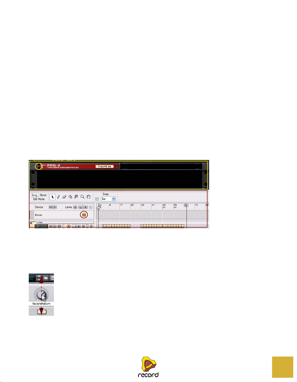
Frames and circles (call-outs)
In pictures throughout this manual there might be circles and/or rectangles highlighting certain areas or objects.
These are indicated by filled lines according to the examples in the picture above. Sometimes these highlighting
frames/circles might also be accompanied by descriptive texts. The different colors of the frames and texts are only
to enhance the contrast to the background picture.
Dashed arrows
A dashed arrow in a picture indicates the directions in which the pointer (or other tool) should be dragged to perform
the desired operation. The example in the picture above shows in which directions (up and down) to drag the pointer
to change the knob’s setting.
INTRODUCTION
25
Authorization and the Ignition Key
Record uses an authorization system designed to be as flexible as possible, while at the same time providing the best
possible copy protection for the product. Here's how it works:
• The core of the authorization system is your license number, which is registered to your user account on the
Propellerhead web site.
• You then use this license to authorize your Propellerhead Ignition Key.
Once this is done, you can use this USB key to run Record in Authorized Mode, anywhere and on any computer.
• If you don't have the Ignition Key at hand, you can still run Record in authorized mode, provided that you have
a working internet connection.
The program will then contact the Propellerhead web site and verify that Record is registered to your user account.
• Finally, should you be without both Ignition Key and internet connection, you can run Record in demo mode.
This is also the mode you use if you are trying out the program, but haven't yet purchased it. In this mode, you can
work as usual and even save your work. You cannot, however, open songs in demo mode (for details, see “Running
Record in demo mode”).
Registering and authorizing Record
To be able to run Record in authorized mode (see “Running Record with the Ignition Key” and “Running Record with
Internet Verification”), the program must be registered to your account on the Propellerhead web site.
! If you purchased Record directly from the Propellerhead web site, the Record license has already been regis-
tered to your user account.
This means you can run Record using Internet Verification, right away (see “Running Record with Internet Verifica-
tion”). However, when you receive your Propellerhead Ignition Key you need to authorize it, so please read on!
Here's how you register and authorize your copy of Record.
! Note that a working internet connection is required to be able to perform the following steps.
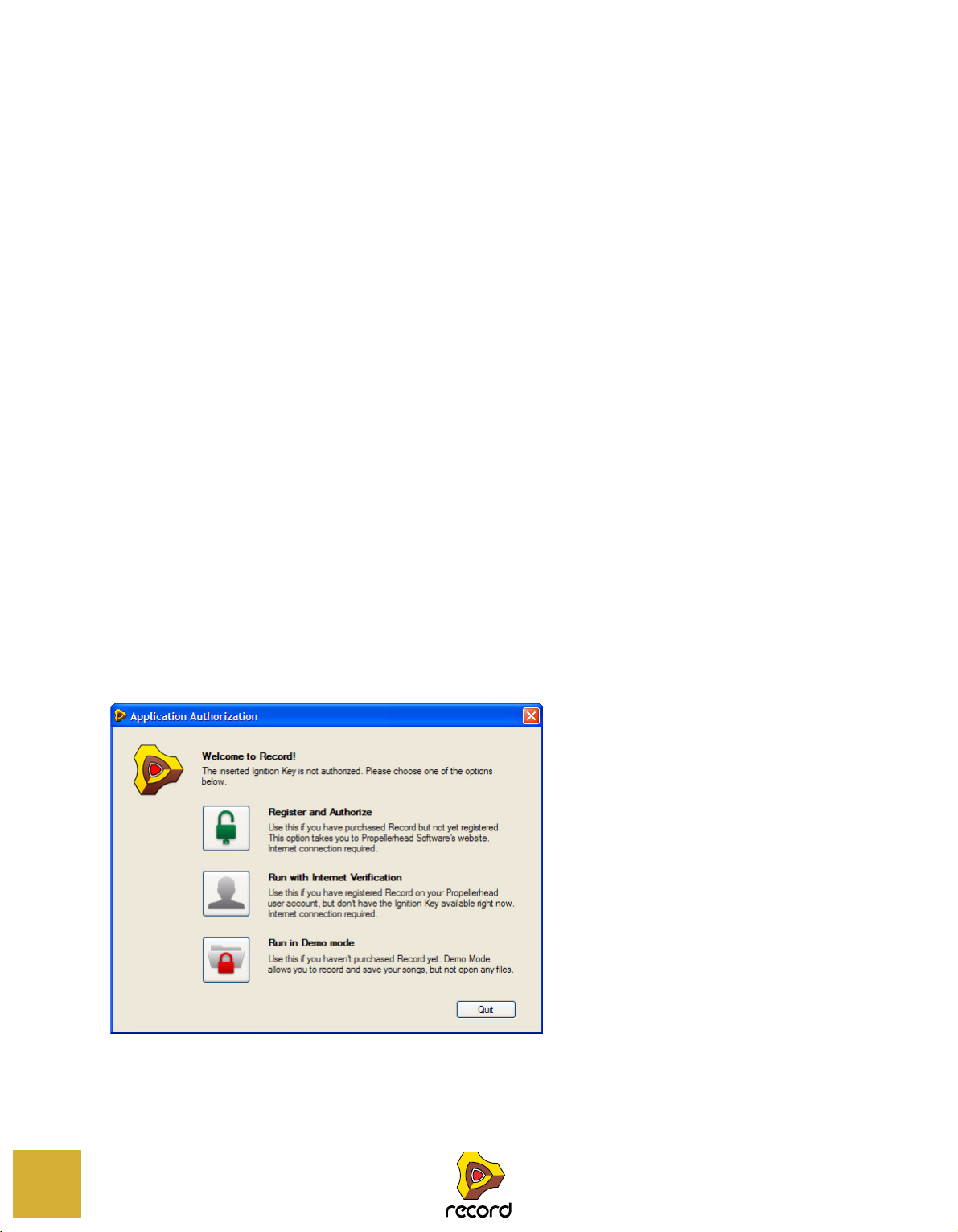
1. Launch Record.
When you start Record for the first time, this window is displayed:
26
INTRODUCTION
2. Click on the Register and Authorize button.
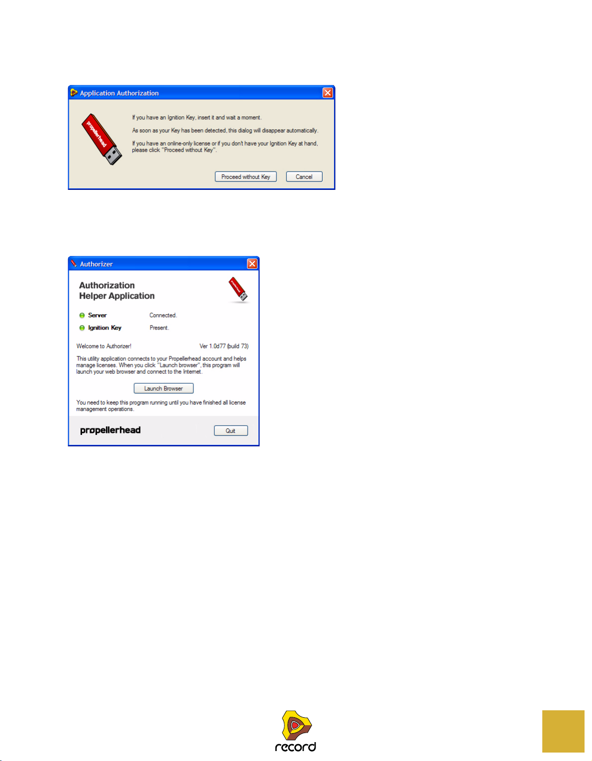
The following dialog appears:
3. Insert the Ignition Key in a free USB port on your computer.
If you don't have the Ignition Key at hand, but just want to register Record, click "Proceed without Key".
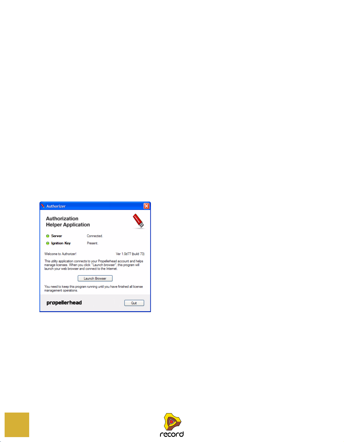
Record will start the Authorizer, an application which manages authorizations and the Ignition Key. This will guide
you throughout the rest of the registration and authorization process:
4. Click the "Launch Browser" button.
The default Internet browser on your computer is launched and will direct you to the Record registration and authorization page at the Propellerhead web site.
5. Enter your user name and password and log in on your Propellerhead account.
If you don't have an account already, click on the "Create account" link and follow the instructions to register a
new account.
The following step depends on the situation:
6. If you haven't already registered Record, you will be asked to do that: Enter the license number and registration code found in the Record box, then click the button below.
• If your Ignition Key is inserted, the button will be called "Register and Authorize".
Your license will be registered and the Ignition Key will be authorized with your license.
If your Record license is already registered, it will be shown on the web page. Select it and click the button called
"Authorize". This authorizes your Ignition Key with your license.
• If you don't have the Ignition Key inserted, the button will be called "Register".
Your license will be registered, allowing you to run Record in authorized mode with Internet Verification. You can
later return to authorize your Ignition Key.
INTRODUCTION
27

• If your Record license is already registered, it will be shown on the web page.
Select it and click the button called "Authorize". This authorizes your Ignition Key with your license.
7. When you're done, go back to Authorizer and click Quit.
Record will restart automatically, and you will now be able to run the program in Authorized Mode.
Running Record with the Ignition Key
If you launch Record with an authorized Ignition Key inserted, the program will simply start without further ado.
q From now on, always insert the Ignition Key before starting your computer and launching Record. This way Re-
cord will start up immediately, without the Application Authorization procedure.
When you have an authorized Ignition Key inserted in your computer, it’s no longer necessary to have an Internet connection when running Record.
Running Record with Internet Verification
If you launch Record without an Ignition Key inserted, the following window appears:
28
1. Click on the "Run with Internet Verification" button.
! Note that this requires a working internet connection (and that your Record license has been registered to your
user account as described in “Registering and authorizing Record”).
2. Enter the username and password for your Propellerhead account in the dialog that appears.
Record launches in Authorized Mode.
• Should you at any point insert your authorized Ignition Key, internet connection will no longer be required.
• It is not possible to run two instances of Record (on different computers) authorized to the same user account.
Record will then enter demo mode (see “Running Record in demo mode”).
INTRODUCTION
Running Record in demo mode
If you don't have a Record license, or if you're without both your Ignition Key and a working internet connection, you
can run Record in demo mode:
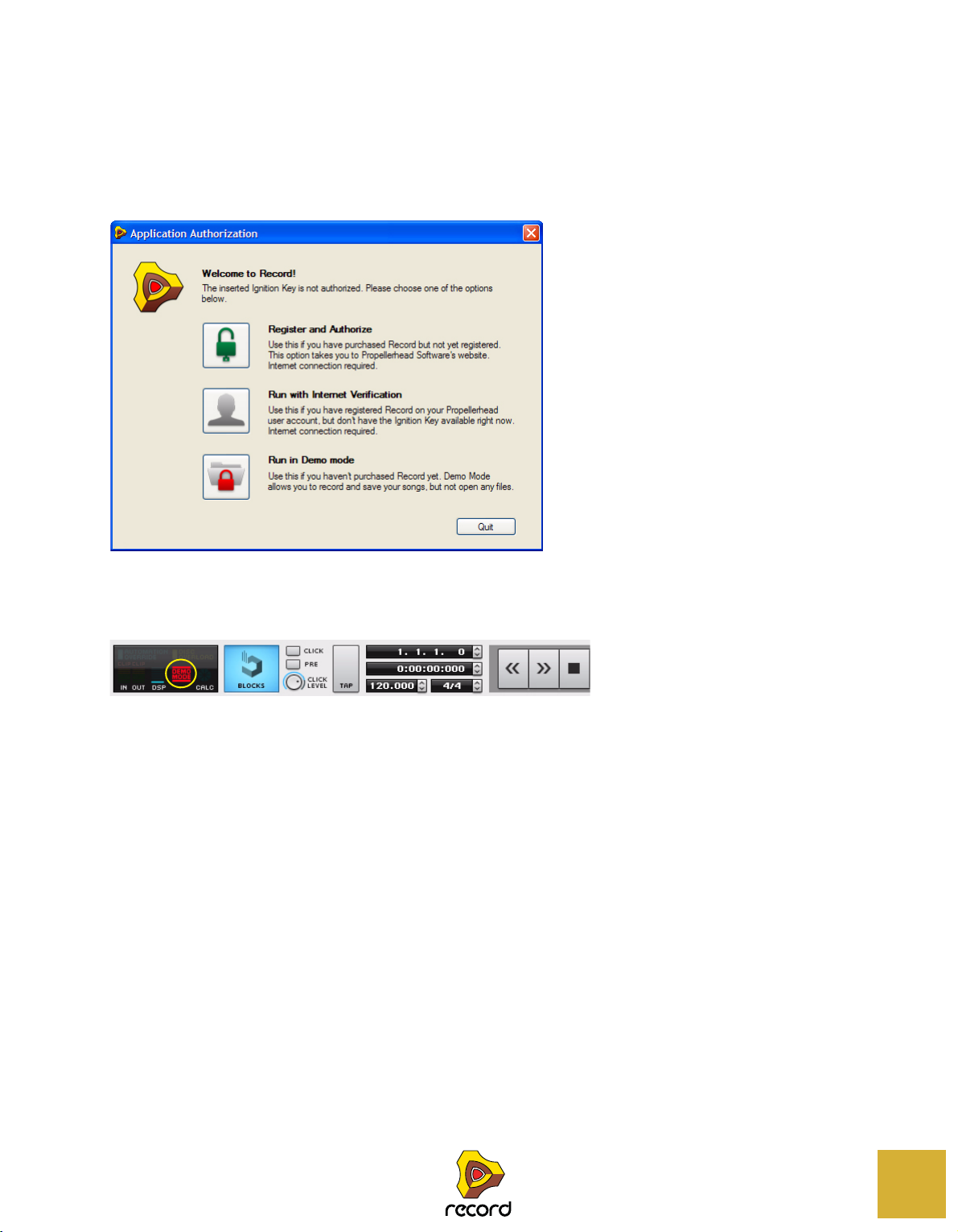
1. Launch Record.
The following window appears:
2. Click on the "Run in Demo mode" button.
Record launches in Demo Mode.
The Demo Mode alert lights up to the left on the Transport Panel:
Running Record in Demo Mode allows you to perform all operations as in Authorized Mode, with two exceptions:
• You cannot export audio or bounce mixer channels to disk.
• You cannot open songs.
The only songs that can be opened in Demo Mode are the dedicated demo songs (file extension ".recdemo"). See
“Opening a Record Demo Song”.
If you remove your Ignition Key or lose the Internet connection while running Record with Internet Verification, the
program will automatically enter Demo Mode. You can continue working, and save your songs as usual. When you put
back the Ignition Key or reconnect to the Internet, Record will automatically revert to authorized mode and the Demo
Mode alert will go out on the Transport Panel.
INTRODUCTION
29
Running Record in combination with Reason
If you have Reason version 5 registered and installed on your computer, Record will automatically detect this when
you launch the program. All Reason devices will be available in Record, and Reason songs can be opened (see
“About opening Reason Songs in Record (Record+Reason)”).
Registering Reason
If you haven't already registered Reason, please go to www.propellerheads.se, click "Your Account" and follow the instructions for registering Reason. You will need the license number and registration code on the Authorization Card
that was included in the Reason box.
After registering Reason to your user account, you can run Record+Reason with Internet Verification as described in
“Running Record with Internet Verification”.
Authorizing the Ignition Key for Reason
To be able to run Record+Reason in authorized mode with the Ignition Key, you need to authorize the key with your
Reason license:
1. Insert the Ignition Key in a free USB port.
2. Launch Record.
An alert will appear, telling you that Reason has been found but isn't authorized.
3. Click the “Authorize” button.
This launches the Authorizer application, which will guide you throughout the rest of the authorization process:
30
4. Click the "Launch Browser" button.
The default Internet browser on your computer is launched and will direct you to the Propellerhead web site.
5. Enter your User name and Password and log in to your Propellerhead Account.
6. Click on the “Your Products” link.
This takes you to the "Your Products" page, listing all products that are registered to your user account.
7. Locate the Reason Version 5 license in the list and click the "Manage license" link next to the license.
8. On the Manage License page, you are asked if you want to authorize the inserted Ignition Key with your Reason license. Click the Authorize button.
The Authorizer will now write the Reason license to the Ignition Key. This make take a short while.
INTRODUCTION

9. When the web page tells you that the Authorization process is complete, return to the Authorizer and click the
Quit button.
Record will restart. From this point on all Reason devices will be available on the Create menu and Device Palette
in Record.
If Record cannot find your Reason installation
If you have Reason installed in a non-standard location, or if you have changed the name of the Reason folder, Record may not find the Reason installation. If this happens, you can specify the location of the Reason folder manually:
1. Open the Preferences dialog from the Edit menu (Windows) or Record menu (Mac).
2. Select the File Locations page.
It contains a Reason Application Folder setting.
3. Click the "Change..." button in the Reason Application Folder section.
This opens a standard file browser dialog.
4. Navigate to where your Reason folder is, select the Reason folder and click Choose.
The browser closes and the location (path) you specified is shown in the Reason Application Folder on the Preferences page.
• If you get the "No Reason Installation Found" message when you click the Choose button, this is because the
program couldn't find a valid Reason version in the folder you specified.
Make sure that you selected the actual folder containing the Reason application.
! Note that Record Version 1.5 requires Reason Version 5.
5. Restart Record for the change to take effect.
Now, the program will find your Reason installation and give you access to all Reason devices in Record.
INTRODUCTION
31

Reassigning the Function Keys in Mac OS X
When you work with Record, you will do a lot of navigating between the three main areas - the main mixer, the rack
and the sequencer. The quickest way to switch between these areas is to use the function keys F5, F6 and F7 (see
“Navigating between the areas” for details). Also, the F4 and F8 keys are shortcuts for showing and hiding the On-
screen Piano Keys window and the Tool Window, respectively.
However, on many Macintosh models (especially MacBooks), the function keys double as hardware control buttons.
For example, they might control the volume of the built-in speaker, the display brightness or keyboard backlight. To
make these keys actually work as function keys for software such as Record, you need to hold the "Fn" key while
pressing them.
This can work perfectly OK, but to get the best workflow in Record we recommend that you change this behavior, so
that pressing e.g. the F5 key actually sends "F5" to Record (and you hold down the Fn key to get the hardware control functions instead). Here is how you change this:
1. Open the System Preferences in Mac OS X and select the "Keyboard & Mouse" item.
The "Keyboard & Mouse" preferences are shown.
2. Select the "Keyboard" tab and make sure the checkbox "Use all F1, F2, etc. keys as standard function keys" is
ticked.
Now you can use F4-F8 for controlling functions in Record. To use hardware control features such as volume and
display brightness, you need to hold down the "Fn" key before pressing the function keys.
32
Some function keys might also be pre-assigned to Mac OS X keyboard shortcuts, which will have priority over software such as Record. This is easily changed:
3. Click the “Keyboard Shortcuts” tab in the “Keyboard & Mouse” window.
The Keyboards & Mouse Preferences window shows a list of keyboard shortcuts assigned to system functions.
For example, [Cmd]+[F5] is assigned to turn VoiceOver on or off. In Record, this is the keyboard shortcut for detaching the main mixer into a separate window.
INTRODUCTION

4. Scroll down to the "Turn VoiceOver on or off" item and either remove the tick from the checkbox or assign it to
another keyboard shortcut.
5. Scroll down further to the "Spaces" item (keyboard shortcut F8) and either remove the tick from the checkbox
or assign it to another keyboard shortcut.
In Record [F8] is assigned to show/hide the Tool Window.
6. Now, you’re finished with the settings and can close the “Keyboard & Mouse” window.
From now on, the function keys and keyboard shortcuts will perform their intended functions in Record.
INTRODUCTION
33

34
INTRODUCTION

Chapter
Common Operations and Concepts
2

About this chapter
Main Mixer
Rack
Sequencer
Transport Panel
This chapter gives a basic overview of the Record application and describes general methods and techniques employed throughout the Propellerhead Record software. It also explains the terminology used throughout the program,
manuals and help files.
Areas, windows and basic navigation
Song window overview
36
A Record Song window with its Main Mixer, Rack and Sequencer areas
The Record graphical user interface is divided into three main areas:
•The Main Mixer
The Main Mixer is located at the top in the Record Song window. Here are the channel strips for the audio and instrument tracks in your song.
•The Rack
The Rack is where all sound and effects devices you use in your song are located. The Rack resembles a traditional hardware rack, where sound modules and effects units can be mounted.
• The Sequencer
The Sequencer is where you record your audio and instrument tracks. Here you can also record automation of device parameters in the Rack and of channel strip parameters in the Main Mixer. The Sequencer also incorporates
the Transport Panel, where all sequencer transport controls are located.
The areas can be viewed together, as in the picture above, in pairs or separately - see “Navigating between the ar-
eas”. The areas can also be resized - see “Resizing”.
COMMON OPERATIONS AND CONCEPTS

The Main Mixer
Channel Strip Navigator
Mixer Navigator
Maximize Main Mixer button
Detach Mixer button
The Main Mixer with the Fader sections currently scrolled into view
In the Main Mixer, all channel strips of the Record song are visible. You can scroll vertically in the Main Mixer by clicking and dragging inside the frame in the Channel Strip Navigator to the right. This way you will be able to access all
channel strip parameters. If you have a lot of channels present you can also scroll horizontally by clicking and dragging the frame in the Mixer Navigator at the top.
By pressing function key [F5], or by clicking the Maximize Main Mixer Area button at the top right of the Channel
Strip Navigator, you can maximize the Main Mixer to cover the entire Record Song window.
The Maximize and Detach buttons for the Main Mixer
Below the Maximize Main Mixer Area button is the Detach Main Mixer button. Clicking on this, or holding [Ctrl](Win)
or [Cmd](Mac) and pressing [F5], will detach the Main Mixer and place it in a separate window. This is especially useful if you are using multiple screens with your computer.
For more details about the Main Mixer, please refer to “The Main Mixer” chapter.
COMMON OPERATIONS AND CONCEPTS
37

The Rack
Rack
Navigator
Maximize Rack button
Detach Rack button
The Rack with two rack columns next to each other, and the Rack Navigator to the right
In the Rack, all instruments, effects and mixer channel devices of the Record song are visible. You can scroll vertically
and horizontally in the Rack by clicking and dragging the frame in the Rack Navigator. You could also click anywhere
outside the frame in the Rack Navigator to immediately jump to the desired position. Alternatively, place the pointer
on either of the wooden “side panels” in the rack, and click and drag in any direction. This way you will be able to access all devices in the rack.
By pressing function key [F6], or by clicking the Maximize Rack Area button at the top right of the Rack Navigator,
you can maximize the Rack to cover the entire Record Song window.
The Maximize and Detach buttons for the Rack
Below the Maximize Rack Area button is the Detach Rack button. Clicking on this, or holding [Ctrl](Win) or
[Cmd](Mac) and pressing [F6], will detach the Rack Area and place in a separate window. This is especially useful if
your are using multiple screens connected to your computer.
When you detach the Rack, the Transport Panel at the bottom of the Sequencer will be duplicated below the Rack in
the new window. This way, you will be able to control the Sequencer transport functions without needing to change
window.
For more details on how to work with the Rack, refer to “Working with the Rack”.
38
COMMON OPERATIONS AND CONCEPTS

The Sequencer
Track Navigator
Song Navigator
Track List
Edit/Arrangement Pane
Toolbar
Ruler
Maximize Sequencer button
The Sequencer with a number of recorded audio tracks
To the left in the Sequencer, all tracks in the Record song are listed in the Track List. By clicking on a track in the
Track List you select the track for playback from a connected MIDI master keyboard and/or for recording.
At the top to the left are the Song View, Blocks View and Edit Mode buttons and the Toolbar, with various sequencer
editing tools.
The big center section of the Sequencer is called the Edit/Arrangement Pane. Here is where all recorded sequencer
data is displayed.
You can scroll and zoom in the Sequencer by using the Track Navigator to the right and the Song Navigator at the
bottom of the Sequencer - see “Scrolling” and “Zooming in the Sequencer”.
By pressing function key [F7], or by clicking the Maximize Sequencer Area button at the top to the right of the Track
Navigator, you can maximize the Sequencer to cover the entire Record Song window.
The Maximize button for the Sequencer
For more details about the sequencer, refer to “Sequencer Functions”.
COMMON OPERATIONS AND CONCEPTS
39

The Transport Panel
At the bottom of the Record Song window is the sequencer Transport Panel. From here you control the sequencer
transport functions, such as Rewind, Fast Forward, Stop, Play and Record. You can also set Tempo and Time Signature and various other parameters.
The Transport Panel is always available together with the Sequencer. If you have detached the Rack, a duplicate of
the Transport Panel will be also present in the Rack window.
To the left on the Transport Panel are indicators for Audio In and Out levels, DSP Load, Disk Overload, Audio Calculation, Demo Mode and Automation Override status.
By clicking the small grey triangle button to the far upper right you can hide the Transport Panel if you like.
For more details about the Transport Panel, please refer to “Transport Panel details”.
The ReGroove Mixer
To the right of the Toolbar in the Sequencer is a big “G” button. Clicking this will bring up the ReGroove Mixer.
40
The ReGroove Mixer is used for adding advanced grooves to your instrument tracks in the Sequencer.
To hide the ReGroove Mixer, just click the “G” button again.
For more details about the ReGroove Mixer, please refer to “The ReGroove Mixer”.
COMMON OPERATIONS AND CONCEPTS

Navigating between the areas
By using the functions keys [F5], [F6] and [F7] you can quickly and easily navigate between the different areas of the
Record window.
D Press [F5] to toggle between a maximized Main Mixer area and the previous view.
D Press [F6] to toggle between a maximized Rack area and the previous view.
D Press [F7] to toggle between a maximized Sequencer area and the previous view.
! If the Main Mixer and/or the Rack are detached in separate windows, you have to press [F5] to view the Main
Mixer window, [F6] to view the Rack window and [F7] to view the Sequencer window. It’s not possible to toggle
between views/windows by repeatedly pressing the same function key.
It’s also possible to press any of the [F5], [F6] and [F7] function keys simultaneously in different combinations to
switch between combined area views. For example, pressing [F5] and [F6] simultaneously will bring up a combined
maximized view of the Main Mixer and Rack areas in the Record window. The Sequencer area will then automatically
become minimized
Pressing all three function keys simultaneously, or holding [Ctrl](Win) or [Cmd](Mac) and pressing [F7], will bring up
all areas together, equally sized.
! Note that using three function keys simultaneously is not supported on all computer keyboards.
! If the Main Mixer and/or the Rack are detached in separate windows, pressing any of the [F5], [F6] and [F7]
keys in combination will automatically attach the corresponding (detached) window(s).
To select an area for editing etc., simply click anywhere in the desired area. The selected area will then be surrounded
by a thin blue rectangle.
Showing/hiding the Navigators
Deselecting “Show Navigators” on the Options menu will hide all navigators in all areas of the Record song document
window(s). These include the Mixer Navigator and Channel Strip Navigator in the Main Mixer, the Rack Navigator in
the rack as well as the Track Navigator and Song Navigator in the sequencer.
Selecting “Show Navigators” on the Options menu will show all navigators in the Record song document window(s).
Using several Record Song windows
You can have several Songs open at the same time. Each Song will appear in a separate Song window, complete with
Main Mixer, Rack, Sequencer and Transport Panel. Each Song window can be moved, minimized and resized using
the standard Windows and Mac procedures.
COMMON OPERATIONS AND CONCEPTS
41

The Tool Window
The Tool Window is a floating window which features three (or four, if you run Record+Reason) tabs that contain
short-cuts for creating devices, editing in the sequencer, editing grooves for the ReGroove mixer and sample editing
functions. The Tool Window can be accessed from the Window menu.
D Open the Tool Window by selecting “Show Tool Window” from the Window menu. Alternatively, press [F8].
The [F8] key can be used for toggling between showing and hiding the Tool Window.
42
The Tool Window
• See “Creating devices” for information on how to use the “Device Palette” tab.
• See the “Note and Automation Editing” chapter for information on how to use the various functions of the “Sequencer Tools” tab.
• See “The ReGroove Mixer” chapter for information on how to use the functions of the “Groove Settings” tab.
• See the “Sampling (Record+Reason)” chapter for information on how to use the functions of the “Song Samples” tab.
COMMON OPERATIONS AND CONCEPTS

The On-screen Piano Keys window
The On-screen Piano Keys floating window features a virtual keyboard which lets you play instrument devices without needing to have a MIDI master keyboard connected to your computer. The On-screen Piano Keys window can be
accessed from the Window menu.
D Open the On-screen Piano Keys window by selecting “Show On-screen Piano Keys” from the Window menu.
Alternatively, press [F4].
The [F4] key can be used for toggling between showing and hiding the On-screen Piano Keys window.
The On-screen Piano Keys window in “Mouse” mode
See “On-screen Piano Keys” for more information.
COMMON OPERATIONS AND CONCEPTS
43

General window techniques
Resizing
Adjustable dividers in the Record Song window
Between each area in the Record Song window are dividers that separate the areas from each other. Some of the dividers can be adjusted, making it possible to resize the areas. The horizontal dividers between the Main Mixer and
Rack, and between the Rack and Sequencer can be adjusted, as well as the vertical divider to the left of the Rack
Navigator in the Rack. Adjustable dividers have four (Windows) or one (Mac) small “dents” in the center.
When you place the mouse pointer on this type of divider, the pointer will change to a double-arrow symbol. Clicking
and dragging these types of dividers makes it possible to resize the adjacent areas.
44
COMMON OPERATIONS AND CONCEPTS

Scrolling
Record offers a few different options for scrolling in the different areas.
Scrolling with the Navigators
Navigators in the Record Song window
Whenever there is information “outside” the visible screen area, you may want to scroll to the desired destination. The
Record Song window features a number of Navigators that can be used for scrolling. Navigators are present by default in the Main Mixer, in the Rack and in the Sequencer.
The Main Mixer and the Sequencer have both horizontal and vertical Navigators.
The Rack has only one Navigator which can be used for scrolling both vertically and horizontally (when using more
than two rack columns next to each other). The Rack Navigator can also be resized by moving the vertical divider to
the left of the Rack Navigator. Resizing the Rack Navigator will also resize the rack devices inside the Navigator,
making them easier to distinguish.
D To scroll with a Navigator, click anywhere inside the frame in the Navigator and drag the frame to the desired
position.
As the pointer enters the frame, it automatically switches to a hand symbol.
D Alternatively, click anywhere in the Navigator area to immediately jump to the desired position.
• At high zoom values in the Sequencer, you can hold [Shift] and drag the Song Navigator frame to scroll with
greater precision.
COMMON OPERATIONS AND CONCEPTS
45

Scrolling with the Hand tool
Scrolling with the Hand tool in the Rack
In the Rack and Sequencer, you can also use the Hand tool for scrolling the view.
1. In the Rack, place the pointer on either of the wooden side panels of a rack column.
The pointer will switch to a hand symbol.
2. Click and drag the rack vertically and/or horizontally to scroll in the rack, as shown in the picture above.
If you are using only a single rack column, it’s only possible to scroll vertically.
In the Sequencer you have to manually switch to the Hand Tool by selecting it from the sequencer Toolbar. With the
Hand Tool selected, you can scroll in any direction on the Edit/Arrangement Pane. Refer to “Hand Tool” for more in-
formation.
Zooming in the Sequencer
In the Sequencer it’s possible to zoom in and out using the Track Navigator and Song Navigator. You can also use the
Magnifying Glass Tool on the Sequencer Toolbar - see “Magnifying Glass Tool”.
q See also “Scrolling and zooming using a wheel mouse”.
Zooming vertically in the Sequencer
D To zoom in vertically in the Sequencer arrangement, and thus increase the Track height, click on the “+” mag-
nification button below the Track Navigator:
Increase the Track height by clicking the + magnification button below the Track Navigator
D To zoom out vertically, click on the “-” magnification button.
• When the Sequencer is in Edit Mode, individual vertical zoom controls become available.
46
COMMON OPERATIONS AND CONCEPTS

Zooming horizontally in the Sequencer
You can also zoom in and out horizontally in the Sequencer by using the Song Navigator.
D To zoom in horizontally, click on the “+” button to the left in the Song Navigator.
D To zoom out horizontally, click on the “-” button to the left in the Song Navigator.
D To zoom in and out horizontally, click and drag a Song Navigator handle sideways.
The pointer changes to a double arrow symbol and you can now zoom in by resizing the Song Navigator Frame.
D [Shift]-click on a Song Navigator handle and drag horizontally to zoom in and out symmetrically.
D By right-clicking (Win) or [Ctrl]-clicking (Mac) inside the Song Navigator frame you can both scroll (drag side-
ways) and zoom (drag up or down) simultaneously.
Scrolling and zooming using a wheel mouse
If you’re using a mouse equipped with a scroll wheel, this can be used for the following scrolling and zooming operations:
Scrolling in the Main Mixer with a wheel mouse
D Spin the scroll wheel to scroll vertically in the Main Mixer.
D Press [Shift] and spin the scroll wheel to scroll horizontally in the Main Mixer.
Scrolling in the Rack with a wheel mouse
D Spin the scroll wheel to scroll vertically in the Rack.
D Press [Shift] and spin the scroll wheel to scroll horizontally in the Rack.
Note that the Rack must have at least two rack columns next to each other for this to work.
Scrolling in the Sequencer with a wheel mouse
D Spin the scroll wheel to scroll vertically on the Edit/Arrangement Pane.
D Press [Shift] and spin the scroll wheel to scroll horizontally on the Edit/Arrangement Pane.
! Note that scrolling horizontally cannot be done when the Song Navigator frame is fully expanded.
Zooming in the Sequencer with a wheel mouse
D Press [Ctrl](Win) or [Cmd](Mac) and spin the scroll wheel to zoom in and out vertically on the Edit/Arrange-
ment Pane.
D Press [Ctrl]+[Shift](Win) or [Cmd]+[Shift](Mac) and spin the scroll wheel to zoom in and out horizontally on
the Edit/Arrangement Pane.
COMMON OPERATIONS AND CONCEPTS
47

Editing parameters
Since a large part of Record is laid out like “real” hardware devices, such as the Main Mixer, instrument and effect devices etc., almost all controls are designed like their real world counterparts - mixer faders, effect unit knobs, transport
buttons, etc. How to adjust these controls is described in the following paragraphs.
Knobs
D To “turn” a knob, point at it, hold down the mouse button and drag up or down (as if the knob was a vertical
slider).
Dragging upwards turns the knob clockwise and vice versa.
D If you press [Shift] and drag, the knob will turn slower, allowing for higher precision.
You can also adjust the knob precision with the “Mouse Knob Range” setting on the General page in Preferences.
This dialog is opened from the Edit menu (or from the Record menu if you are running Mac OS X).
D To reset a knob to its default value (usually zero, center pan or similar), press [Ctrl](Win) or [Cmd](Mac) and
click on the knob.
Faders and sliders
D To move a fader or slider, click on the handle and drag in the fader/slider direction.
D You can also click anywhere on the fader/slider to instantly move the handle to that position.
D If you press [Shift] and drag, the fader/slider will move more slowly, allowing for higher precision.
D To reset a fader/slider to its default value (usually zero, 100, center pan or similar), press [Ctrl](Win) or
[Cmd](Mac) and click on the fader/slider handle.
48
COMMON OPERATIONS AND CONCEPTS

Buttons
Click on the Fold/
Unfold Button to
unfold the front panel.
Click on the second Fold/
Unfold Button on the
unfolded panel to bring up
the Remote Programmer.
Many functions and modes are controlled by clicking buttons. Many of the buttons in Record have a “built-in” LED, or
the button itself lights up, indicating whether the button is on or not.
Fold/Unfold buttons
Fold/Unfold buttons are distinguished by a small triangle at the top to the left on a device. Clicking on a Fold/Unfold
button will unfold the device panel so that more controls are visible and can be accessed for editing on the screen.
On some devices, such as the RV7000 Advanced Reverb, there are more than one Fold/Unfold button. Clicking on
the second Fold/Unfold button on the unfolded front panel will open up the Remote Programmer panel from which
more parameters can be accessed:
The Fold/Unfold buttons on an RV7000 Advanced Reverb device
COMMON OPERATIONS AND CONCEPTS
49

Multi Mode selectors
or
Some parameters allow you to select one of several modes. There are two different graphical representations of this
in Record.
The multi mode selector type below consists of a button with the different modes listed above it:
D Click the button to step through the modes or click directly on one of the modes printed on the panel, or click
on the corresponding LED, to select mode.
The currently selected mode is indicated by a lit LED.
The multi mode selector type below is a switch with more than two positions:
D To change mode, click and drag the switch, or click directly at the desired switch position (just as when adjust-
ing a slider).
Numerical controls
In Record, numerical values are often displayed in numerical displays with “spin controls” (up/down arrow buttons) on
the side. Some parameter values, such as oscillator and LFO waveforms, are displayed graphically in the displays.
There are two ways of changing values in these types of controls:
D By using the up and down buttons on the spin controls.
To adjust a value in single steps, click on its up or down arrow button. To scroll a value continuously, click on an arrow button and keep the mouse button depressed.
D By clicking and holding the mouse button depressed in the actual display and then dragging the mouse up or
down.
This allows you to make coarse adjustments very quickly.
50
COMMON OPERATIONS AND CONCEPTS

Alpha-numeric controls
or
In Record, alpha-numeric values and/or device presets are displayed in alpha-numeric readouts with “spin controls”
(up/down arrow buttons) on the side. There are two ways to change alpha-numeric/preset values:
D By using the up and down buttons on the spin controls.
To adjust a value or select a preset in single steps, click on the up or down arrow button. To scroll a value continuously, click on an arrow button and keep the mouse button depressed.
D By clicking and holding the mouse button depressed in the actual alpha-numeric display and selecting from
the list that appears.
This allows you to make coarse adjustments very quickly or to immediately change to a preset anywhere in the list.
q This type of control is used to select, e.g., patch and reverb algorithms and some oscillator waveforms.
COMMON OPERATIONS AND CONCEPTS
51

Numerical segment displays
Click the up/down arrow buttons to change
tempo in steps of 1 BPM (the leftmost segment).
Click on the left display segment to select the “whole BPM” value.
Then, either click and drag up or down or click on the up/down arrow
buttons to change tempo in steps of 1 BPM.
Alternatively, type in the new tempo and press [Enter] on the computer
keyboard.
You can also type in a number preceded by [+] or [-] to add or subtract
the number from the current tempo value. Then, press [Enter] on the
computer keyboard.
Click on the right display segment to select the “1/1000 BPM” value.
Then, either click and drag up or down or click on the up/down arrow
buttons to change tempo in steps of 1/1000 BPM.
Alternatively, type in the new tempo and press [Enter] on the computer
keyboard.
You can also type in a number preceded by [+] or [-] to add or subtract
the number from the current tempo value. Then, press [Enter] on the
computer keyboard.
Double-click on the display, type in the new tempo
and press [Enter] on the computer keyboard.
In the numerical segment displays on the sequencer Transport Panel and in the sequencer Inspector, values can be
edited in a number of different ways. The editing principle is exactly the same for the Transport Panel and Inspector
displays, which is shown in the two examples below.
Transport Panel segment displays
The segment displays of the Transport Panel can be edited as shown in the following Tempo display examples. The
Tempo display segments show (from left to right) BPM and 1/1000 BPM:
The other segment displays on the Transport Panel can be edited in the same way as described above.
52
COMMON OPERATIONS AND CONCEPTS

Inspector segment displays
Click the up/down buttons to change the value in
steps of 1 Bar (the leftmost segment).
Click in the display to select either the Bar, Beat,
1/16th note or Ticks segment. Then, click the up/
down buttons to change the value of the selected
segment in steps of 1 unit.
Click in the display to select either Bar, Beat,
1/16th note or Ticks. Then, click and drag the
cursor up/down to change in steps of 1 unit.
Double-click in the display. Then, type in the
desired value and press [Enter].
Click in the display to select either Bar, Beat,
1/16th note or Ticks. Then, type in a number and
press [Enter].
Alternatively, select a segment, type in a number
preceded by a [+] to add or a [-] to subtract the
number from the current value. Then, press [Enter].
The segment displays in the Inspector can be edited as shown in the following Position display examples. The Position display segments show (from left to right) Bars, Beats, 1/16th Note and Ticks:
The other segment displays in the sequencer Inspector can be edited in the same way as described above.
Tool Tips
If you hover with the mouse over a control on a device panel and wait a moment, a tool tip appears. The tool tip shows
the name of the parameter associated with that control and its current value. This helps you fine-tune settings, set
several parameters to the same value, etc.
D You can turn off the Tool Tips function by deactivating the option “Show Parameter Value Tool Tip” in the “Ap-
pearance” section on the General page in Preferences.
COMMON OPERATIONS AND CONCEPTS
53

Context menus
Context menus are “tailored” to contain only menu items that are relevant to the current circumstances. Using the
various context menus allows you to work more quickly and more efficiently with Record.
D To bring up a context menu, right-click (Win) or [Ctrl]-click (Mac) on the desired object, section or area in Re-
cord.
The Mixer 14:2 device panel context menu
q If you are using a Mac with a two button mouse, you may want to set this up so that clicking the right mouse
button generates a [Ctrl]-click. This way, you can right-click to bring up context menus.
The contents of the context menus depend on where you click. These are the primary types of context menus you will
encounter in Record:
Parameter context menus
If you click on an automatable control (a mixer parameter, a device parameter, a fader, etc.), the context menu will
contain the following items:
• Functions for editing and clearing the recorded automation data for the control.
• Functions for associating computer keyboard commands and/or MIDI messages to the parameter.
This allows you to remote control parameters from a MIDI device or from the computer keyboard.
54
COMMON OPERATIONS AND CONCEPTS

Device context menus
If you click anywhere on a device in the Rack (but not on a parameter or display), the context menu will contain the
following items:
The Mixer 14:2 device panel context menu
• Cut, Copy, Paste, Delete and Duplicate Device and Track items, allowing you to rearrange and manage the devices in the rack.
• Commands for managing Device Groups.
• A duplicate of the Create menu, allowing you to create new devices.
• A “Go To” submenu, listing all devices connected to the current device.
Selecting a device from the Go To submenu scrolls the rack to bring that device into view.
• Auto-routing and Disconnect functions.
This allows you to automatically route (connect) or disconnect a selected device in a logical way.
• Combine and Uncombine are used when you want to use the selected device in, or exclude it from, a Combinator setup.
• A Browse Instruments item which lets you browse for sounds for a selected Instrument device.
This item is available only for Instrument devices.
• Additional device-specific items.
If the device is pattern-based, there will be various pattern functions (Cut/Copy/Paste, Clear, Shift, Randomize,
etc.). These affect the currently selected pattern in the device.
If the device uses patches, there will be functions for managing patches.
Depending on the device there may also be various device-specific functions available. For example, the drum machine device has functions for manipulating the pattern for the selected drum sound only, etc.
• “Create Track for ...” and “Delete Track for ...” are used if you want to create a Sequencer Track for the selected
device, or delete the Sequencer Track used for the device without deleting the actual device.
• The “Go To Track for ...” will scroll the corresponding Sequencer Track into view in the Sequencer.
• The “Lock Control Surface to this Device” lets you lock a connected control surface to the selected device.
• The “Track Color” item lets you select color for the associated Sequencer Track (and Main Mixer channel strip,
if the selected devise is an Audio Track device).
COMMON OPERATIONS AND CONCEPTS
55

Main Mixer channel strip context menu
The Channel Strip context menu.
If you click anywhere on a channel strip in the Main Mixer (but not on a parameter or display), the context menu will
contain the following items:
• Cut, Copy, Paste, Delete and Duplicate Channels and Track items, allowing you to rearrange and manage the
channel strips in the Main Mixer.
• Commands for managing Device Groups.
• A duplicate of the Create menu, allowing you to create new devices.
• The “Copy Channel Settings” item lets you copy groups of settings for the selected channel strip.
The groups that can be selected are: “Dynamics”, “Filters and EQ”, “Insert FX”, “FX Sends” and “All”.
• The “Paste Channel Settings” item appears if you have previously copied any channel settings and want to
paste these to the selected channel strip.
• The “Browse Insert FX Patches” lets you browse for, and load, Effect Combi patches to the Insert FX section.
• The “Reset Channel Settings” resets all channel strip parameters to their default values.
It also automatically removes any used Insert FX devices from the channel strip.
• The “Set Remote Base Channel” item lets you set the remote base channel to the selected channel strip.
This is useful when you remote control channel strips from a control surface via MIDI.
• The “Lock Control Surface to this Device” lets you lock a connected control surface to the selected channel
strip.
• The “Track Color” item lets you select color for the associated Sequencer Track (and Main Mixer channel strip,
if the selected devise is an Audio Track device).
• The “Create Send FX” lets you browse for an effects device, or Effect Combi patch, to connect and use as a
send effect.
The send effect will be automatically connected to the first available Send FX connectors of the Master Section
device in the Rack.
56
COMMON OPERATIONS AND CONCEPTS

Rack “background” context menu
If you click in an empty area of the rack, the context menu will contain the following items:
• A Paste Devices and Tracks item, allowing you to paste any copied or cut devices and tracks.
• A duplicate of the Create menu, allowing you to create new devices.
Main Mixer “background” context menu
If you click in an empty area of the Main Mixer, the context menu will contain the following items:
• A duplicate of the Create menu, allowing you to create new devices.
• The “Create Send FX” lets you browse for an effects device, or Effect Combi patch, to connect and use as a
send effect.
The send effect will be automatically connected to the first available Send FX connectors of the Master Section
device in the Rack.
Sequencer context menus
If you click in the Sequencer, the context menus will contain items related to editing tracks, clips and events. The
available items will differ depending on in which section or lane you click (Track List, note lane, etc.), and depending
on whether you click on a note or automation event or not.
For example, the sequencer context menus contain functions for inserting or removing bars, deleting tracks, changing or deleting note and automation events.
COMMON OPERATIONS AND CONCEPTS
57

Undo and Redo
Virtually all actions in Record can be undone. This includes creation, deletion and reordering of devices in the rack,
parameter value adjustments, recording and editing in the sequencer etc. You can undo up to 30 actions.
D To undo the latest action, select “Undo” from the Edit menu, or hold down [Ctrl](Win) or [Cmd](Mac) and press
[Z].
The action to be undone is indicated next to the Undo command on the Edit menu. For example, if your latest action was to delete some device(s) from the rack, the Edit menu will display “Undo Delete Devices and Tracks”.
D To redo the last undone action (“undo the undo operation”), select “Redo” from the Edit menu, or hold down
[Ctrl](Win) or [Cmd](Mac) and press [Y].
Similarly, the action to be redone is shown on the Edit menu.
About multiple Undos and Redos
The concept of multiple undos may require an explanation: You can undo up to 30 actions, or in other words, Record
has an Undo History with up to thirty steps.
Let’s say you have performed the following actions:
1. Created a Mixer device.
2. Created a synth device.
3. Adjusted the Attack parameter of the synth device.
4. Changed the panning for the synth device in the Mixer.
5. Adjusted the playback tempo on the Transport Panel.
After these five actions, the Undo History will look as follows:
58
UNDO
|
5. Adjust tempo
4. Change pan
3. Adjust Attack
2. Create Synth Device
1. Create Mixer Device
If you now select Undo, your latest action (the tempo change) will be undone, and moved to a “Redo list”:
UNDO
|
4. Change pan
3. Adjust Attack
2. Create Synth Device
1. Create Mixer Device 5. Adjust tempo
COMMON OPERATIONS AND CONCEPTS
REDO
|

Selecting Undo again undoes the next action in the list (the panning adjustment):
UNDO
|
3. Adjust Attack
2. Create Synth Device 4. Change pan
1. Create Mixer Device 5. Adjust tempo
REDO
|
If you now select Redo, the most recently undone action will be redone. In this case, your panning adjustment will be
performed again (and added to the Undo History again):
UNDO
|
4. Change pan
3. Adjust Attack
2. Create Synth Device
1. Create Mixer Device 5. Adjust tempo
REDO
|
At this point, you still have the option to Redo the tempo change. But if you instead perform another action (e.g.
change the level of the synth device in the mixer), this would become the action at the top of the Undo History - and
the Redo list would be cleared.
UNDO
|
5. Change level
4. Change pan
3. Adjust Attack
2. Create Synth Device
1. Create Mixer Device (Empty)
REDO
|
You can no longer redo the “undone” tempo change!
COMMON OPERATIONS AND CONCEPTS
59

60
COMMON OPERATIONS AND CONCEPTS

Chapter
On-screen Piano Keys
3
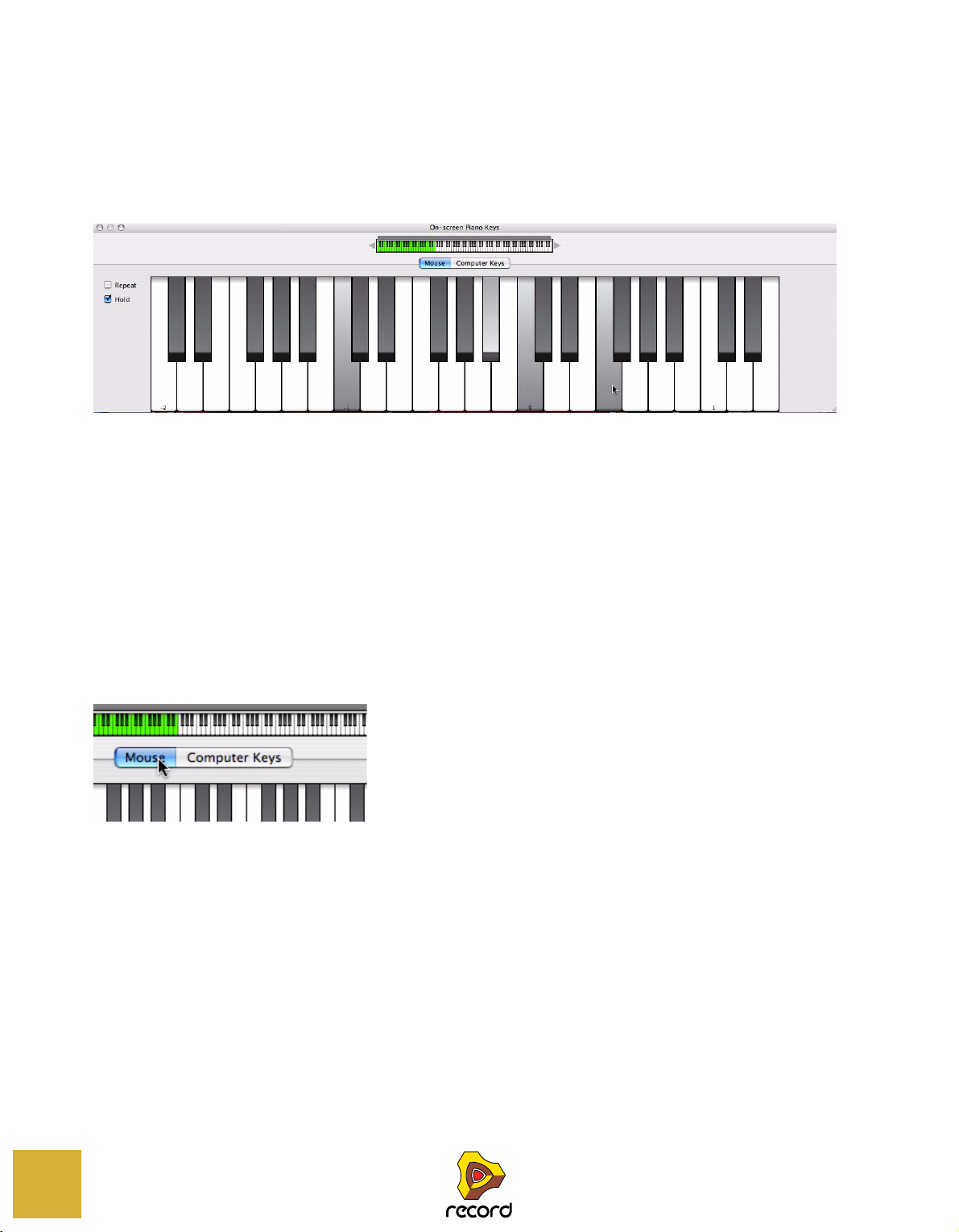
About this chapter
This chapter describes the functions of the On-screen Piano Keys window.
The On-screen Piano Keys window enables you to play instrument devices using either your mouse or computer key-
board. This provides a simple and convenient way to input notes or chords when using the program without an attached MIDI master keyboard.
Using the On-screen Piano Keys
Opening the Piano Keys window
D To open the window, select “Show On-screen Piano Keys” from the Windows menu, or press [F4].
Like the Tool window, the On-Screen Piano Key window “floats” on top of other windows, remaining visible most
of the time.
• You can choose between two basic operational modes to enter notes; “Mouse” or “Computer Keys”.
Mouse Mode is for entering notes with the mouse, and Computer Keys Mode for using the computer keyboard to
enter notes. The two modes are described separately below.
The respective buttons in the middle of the window are used to switch modes.
62
Mode buttons.
• Regardless of mode, the On-screen Piano Keys window always follows Master Keyboard input.
This means that the Piano Keys will trigger the device associated with the track that has Master Keyboard Input.
The Piano Keys input is merged with any attached keyboard/control surface input so you can use both simultaneously.
• The available note range is 10 octaves (C -2 to E 8).
• When the On-screen Piano Keys window is in Mouse mode, you can resize it by clicking and dragging the window frame according to standard procedures.
This is especially useful in “Mouse” mode, since you can adapt the window to show the desired note range.
ON-SCREEN PIANO KEYS

The Keyboard Navigator
Keyboard Navigator
Available notes for the
currently selected instrument
This is present in both modes and shows the total key range. The green area indicates the key range available in the
On-screen Piano Keys window.
Keys that produce sound are indicated by a gray strip above the keyboard in the Keyboard Navigator. This is useful
when playing a patch where only certain keys or key ranges produce sound, e.g. a REX file or a sampler patch (Record+Reason).
Setting Octave range
There are several ways to set the Octave range:
D Click the arrow buttons on either side of the Keyboard Navigator.
Each click will shift one octave up or down.
D Click and drag the green key range area in the Keyboard Navigator.
The current octave number is always shown for the leftmost key - by default the [A] key on the computer keyboard.
Mouse mode
When Mouse Mode is selected, the Piano Keys window will show a standard piano keyboard.
D To enter notes, simply click on the keyboard with your mouse.
As described above, the record enabled track governs what instrument device is played.
ON-SCREEN PIANO KEYS
63

D The keys are velocity sensitive. The higher up on the key you click, the lower the velocity and vice versa.
Velocity=40
Velocity=127
The velocity range is between 40 and 127.
Low and high note velocities.
D The keyboard octave range can be set using the arrow buttons at each side of the navigator keyboard.
Each C key is labeled with the octave number. You can also simply drag the green key range area to where you
want. It will snap to octave ranges.
D In Mouse Mode, the keyboard can be resized both vertically and horizontally.
Resizing horizontally extends or diminishes the key range. By resizing the window vertically you change the key
size for the keyboard, as well as the key range.
Adding sustain
If you press [Shift] when entering notes, the notes will sustain, just like when using a sustain pedal.
Repeat and Hold functions
D The Repeat function will continuously repeat the last clicked note as quarter notes with a quarter note pause
in between (at the current tempo).
This feature can be useful when tweaking synth parameters or browsing for patches. It is activated/deactivated by
checking/unchecking the box.
D The Hold function will keep any keys you click on pressed down for as long as Hold is active.
Hold is activated/deactivated by checking/unchecking the box.
Computer Keys mode
When Computer Keys Mode is selected, the On-screen Piano Keys window shows a graphic (partial) representation
of a computer keyboard. The window cannot be resized in this mode.
64
ON-SCREEN PIANO KEYS

D In Computer Keys Mode you can play notes and chords using your computer keyboard.
The Computer Keys keyboard range is fixed to 18 notes (from C to F), although the octave range will give you access to any notes within the ten octaves shown in the navigator. You can also click on the keys with your mouse
to trigger notes. The numerical keys in the top row are not used to enter notes but to set velocity, see “Velocity”.
D The default layout of the Computer Keys logically reflects the layout of a piano keyboard’s black and white
keys.
The first (leftmost) key represents C and so on up to F an octave above. By default, the [A]-key will play the first C,
the [W]-key a C# and so on, according to piano keyboard standards. If you wish, you can customize the note to key
assignment in the Preferences - Language and Computer Keyboard page (see “On-screen Piano Keys” in Preferences).
Octave range
D Press [Z] or [X] on your computer keyboard to shift one octave down or up, respectively.
There are also “Z” and “X” Octave buttons in the On-screen Piano Keys window that function in the same way.
See “Setting Octave range” for more ways of changing the Octave range.
Repeat and Hold functions
See “Repeat and Hold functions”.
Adding sustain
D Press [Shift] when entering notes to make the notes sustain, just like when using a sustain pedal.
There is also a Sustain button in the On-screen Piano Keys window that has the same functionality.
Velocity
In Computer Keys Mode, note velocity for notes you enter is set using the numerical keys in the top row. The currently
set value is also shown in the Velocity value field. The numerical keys correspond to the following velocity values:
Numerical key
|
11
214
328
442
556
670
784
8 98 (default)
9 112
0 127
Velocity value
|
ON-SCREEN PIANO KEYS
65

Velocity Variation
This feature will randomly vary the velocity values for the notes you enter. There are four modes; None (default),
Light, Medium and Heavy. The degree of velocity variation is as follows.
Item
|
None (default) 0
Light +/- 5%
Medium +/- 10%
Heavy +/- 25%
Variation
|
66
ON-SCREEN PIANO KEYS

Chapter
Audio Basics
4

About this chapter
This chapter contains some useful information about how audio is handled by Record and how the audio is routed.
Some of it may seem a bit technical, but we recommend that you read it to get the most out of Record.
How Record communicates with your audio hardware
Record receives, generates and plays back digital audio - a stream of numerical values in the form of ones and zeroes. For you to be able to record and play back anything, the audio must be converted from analog to digital when
recording, and from digital to analog when playing back through some kind of listening equipment (a set of speakers,
headphones, etc.).
This conversion is most often handled by the audio card installed in your computer, or by an external audio interface
connected via USB or FireWire. To achieve the best possible performance, Record requires that the audio card uses
an ASIO driver on Windows systems. On Mac OS X systems, Record supports Core Audio drivers.
To receive and deliver digital audio to the computer’s audio hardware, Record uses the driver you have selected in the
Preferences dialog. In the Rack on screen, this connection is represented by the Hardware Interface (also known as
the Hardware Device):
The Hardware Interface is always located at the top of the rack
! If you are using Record as a ReWire slave, Record will instead feed the digital audio to the ReWire master ap-
plication (typically another audio sequencer program), which in turn handles the communication with the audio hardware. See “ReWire” for more details.
The Hardware Interface contains 64 input and 64 output “sockets”, each with an indicator and a level meter. There
are also two Sampling Inputs that can be used for sampling audio to sampler devices (Record+Reason). 16 input and
16 output sockets are shown on the main panel, and an additional 48+48 sockets are shown if the “More Audio” button is activated on the main panel. Each one of these indicators represents a connection to an input or output on your
hardware audio interface (or a ReWire channel to another application if you are using ReWire).
However, the number of available inputs and outputs depends on the number of inputs and outputs on your hardware
audio interface. For example, if you are using a standard sound card with stereo inputs and outputs, only the first two
inputs and outputs will be available. In the Hardware Interface, the indicators are lit green for all currently active and
connected inputs and outputs. Activation of inputs and outputs on your hardware audio interface is done on the Audio page in the Preferences dialog (see “Active Input and Output Channels”).
Inputs and outputs that are currently connected have green indicators. Available but un-connected inputs and outputs have yellow indicators and any connections made to unavailable inputs and outputs have red indicators.
68
In this case, Inputs 1 and 2 are available, but not connected, Outputs 1 and 2 are available and
connected, whereas Output 3 is unavailable, but connected on the back of the Hardware Interface.
! You never have to connect any cables to the Audio In jacks of the Hardware Interface to be able to record au-
dio on sequencer tracks. This routing is made internally “in the background”, which means you just have to select audio interface inputs from the Audio Input drop-down list - see “Selecting audio input(s) and defining
mono or stereo”.
AUDIO BASICS

Manual audio routing
In most cases, you will want to have the Main Mixer Master Section device connected to outputs 1 and 2 of the Hardware Interface. This connection is made automatically as soon as you create a new Song document. However, there
might be situations where you want to manually route audio to other outputs of the Hardware Interface. For example
if you want to use the Control Room Outputs of the Main Mixer (see “Control Room output section”).
To send the sound of a device in the Rack to a specific output, you route the device output to the corresponding Output jack on the Hardware Interface. This is done by using the patch cables on the back of the rack, as described in
“Manual routing”. If we flip the rack around, by pressing the [Tab] key, the Hardware Interface looks like this:
On the rear of the Hardware Interface, Inputs 1 and 2 are available but not connected,
Outputs 1 and 2 are available and connected, whereas Output 3 is connected but unavailable.
! You never have to connect any cables to the Audio In jacks of the Hardware Interface to be able to record au-
dio on sequencer tracks. This routing is made internally “in the background”, which means you just have to select audio interface inputs from the Audio Input drop-down list in the sequencer Track List - see “Selecting
audio input(s) and defining mono or stereo”.
Audio quality
The audio quality in a computer based recording system depends on two things:
• The quality of the software calculating the audio.
In our case, this is the Record DSP (Digital Signal Processing) code.
• The quality of the hardware audio interface used for recording and playing back the sound.
Software
• Record uses 32-bit floating point arithmetic for all internal audio operations, with 64-bit summing in the mix
bus in the Main Mixer Master Section.
This ensures the highest possible audio quality throughout the entire signal chain.
• Record supports 16, 20, and 24 bit resolution for input and output audio.
• Record supports all standard sample rates between 44.1 kHz and 192 kHz.
Record also supports lower sampling frequencies, but using a sample rate of less than 44.1 kHz is not recommended since it might affect the audio quality negatively.
• A number of digital audio techniques that reduce the risk of “aliasing”, background noise, unwanted distortion
and “zipper noise” are implemented in Record.
Audio hardware
How good a hardware audio interface actually sounds depends on a number of things; its frequency range and frequency response curve, the resolution (bit depth), the signal to noise ratio, the distortion under various circumstances,
etc. Furthermore, some designs are more prone to disturbance from the other electronics in the computer than others. Such disturbance might add hum or high pitched noise to the signal.
The only advice we can give is that if you are serious about sound, choose your audio hardware carefully!
AUDIO BASICS
69

Audio settings
Sample rate and resolution are properties of digital audio which determine the quality of the sound. Generally, higher
sample rate and resolution result in better audio quality (but also larger audio files and higher demands on computer
performance and audio hardware). The table below shows some common sample rate/resolution combinations:
Sample rate:
|
44.1 kHz 16 bit This is the format used on standard audio CDs.
44.1 kHz –
192 kHz
Resolution:
|
24 bit These are formats used in professional studios and high-end recording
Comment:
|
equipment.
To cater for all different situations, Record supports multiple sample rates and resolutions.
Sample Rate settings for recording and playback
Record handles all internal audio processing in 32-bit floating point resolution, with 64-bit summing in the mix bus in
the Main Mixer Master Section. However, the resolution of the input and output audio is determined by the hardware
audio interface. That is, if you have a 24-bit audio card, Record will record and output audio in 24-bit resolution, and
if you have a 20-bit audio card, audio will be recorded and played back in 20-bit resolution.
The recording and playback sample rate can be specified on the Audio tab in the Preferences dialog (accessed from
the Edit menu (Win) or Record menu (Mac)):
D Select the desired sample rate from the drop-down menu.
Note that the available options on this pop-up menu depend on which sample rates are supported by the audio
hardware.
! Record supports multiple sample rates in the same song!
Record allows import (or recording) of audio of any sample rate. If the original sample rate of a recording is different than the rate currently set for the audio card, Record will automatically do a sample rate conversion.
First, a real-time sample rate conversion algorithm is used (allowing the audio to be played back immediately).
Meanwhile, in the background, the program calculates a sample rate conversion of the highest quality, which will
be used as soon as it is calculated. The CALC progress indicator on the transport panel lights up whenever the
program is doing high quality calculations in the background:
70
The CALC progress indicator on the Transport Panel appears when Record performs high quality audio calculation
AUDIO BASICS

Buffer Size settings
The Buffer Size can be adjusted on the Audio tab in the Preferences dialog (accessed from the Edit menu (Win) or
Record menu (Mac)):
D Select Buffer Size by clicking and dragging the slider sideways.
The trick here is to find the optimum relationship between audio quality, DSP Load and latency. Experiment with different Sample Rate settings in combination with different Buffer Size settings to get the best result.
A professional audio interface used together with a state-of-the-art computer should normally be able to handle a
combination of a high sampling frequency (96 kHz) and a small Buffer Size (64-128 samples) without problems. A
budget priced audio interface normally requires a lower sampling frequency (44.1 kHz) in combination with a little
higher Buffer Size (256-512 samples).
See “About latency” for more information about buffer size and latency.
CPU Usage Limit settings
In the “Miscellaneous” section on the “General” page in Preferences, you can define an upper limit for the CPU usage. If the DSP Load should exceed this set limit, the Record application will stop receiving and outputting sound. If
this happens, you might have to change the audio settings (see “Sample Rate settings for recording and playback”
and “Buffer Size settings”) - or remove tracks and/or devices from your song. By default, the “CPU Usage Limit” is set
to 80%. This is where the CPU load usually starts to make the sound crackle and distort.
About MultiCore Audio Rendering
Record fully supports multicore audio rendering. This means that if your computer has multiple CPU Cores (Dual
Core or Quad Core, for example), or multiple CPUs, Record takes advantage of this to significantly enhance the performance. A higher system performance allows for more tracks and devices in your songs.
If your computer has a multi-core CPU, or multiple CPUs, MultiCore Audio Rendering is active by default, as indicated
on the “General” page in Preferences:
AUDIO BASICS
71

Master Tune setting
The Clip indicators will stay lit for a short
moment, to make them easier to spot.
If the audio out level is, or has been,
too high, the Clip indicators in the
Master Section will stay lit until you
click the “Reset” button.
Audio Out Clip indicators
Reset button
By default, Record plays back a “middle A” at 440 Hz, which is the standard tuning in most instruments. However, if
you are playing Record together with other instruments, you may want to adjust the tuning:
1. Select “Preferences...” from the Edit menu (Win) or Record menu (Mac).
2. Select the “Audio” page from the drop-down menu.
3. Adjust the global tuning with the Master Tune slider or button controls.
D If you like, you can also adjust the Master Tune during playback.
! The Master Tune setting affects the tuning of all sound sources in Record, including the Tuner function on the
Audio Tracks. It also affects the tuning of the Redrum and Dr.Rex loop player, if you run Reason with Record.
About audio levels
When recording and playing back in Record, you should keep an eye on the Audio In and Audio Out Clip indicators
on the Transport Panel, or on the Hardware Interface and the Big Meter. You should also keep an eye on the clip indicators on the Main Mixer Master Section. If any of the clip indicators light up, the audio level is too high, resulting in
clipping (digital distortion).
The Clip indicators on the Audio In and Audio Out meters on the Transport Panel
The Clip indicators in the Master Section of the Main Mixer
72
AUDIO BASICS

! Note that the Main Mixer Master Section Clip indicators will only work if there are no other devices connected
Channel Selection buttons
for the “Big Meter”
The “Show Big Meter” button
Clip indicators
Reset
button
Channel Selection knob
for the “Big Meter”
between the Master Section device and the Hardware Interface!
The Big Meter on the Hardware Interface
D To remedy Audio In clipping, adjust the level at the input source, i.e. on the hardware audio interface or on the
preamp connected to the hardware audio interface.
! When recording or sampling external audio signals, clipping cannot be adjusted in the Record application - it
must be adjusted at the audio input source!
! When sampling audio internally from devices in the rack, you have to adjust the Output Level on the source de-
vice to make sure clipping doesn’t occur in the Hardware Interface (Record+Reason).
D To remedy Audio Out clipping, lower the master level on the Mixer (or other device) that is connected to the
Hardware Interface, until Audio Out clipping doesn’t light up on playback.
You could also use the MClass Maximizer as an insert effect on the Master Section in the Main Mixer to ensure
that clipping never occurs - see “The MClass Maximizer”.
D To get a better overview of the levels, bring up the Big Meter on the Hardware Interface, by clicking the “Big
Meter” button on the front panel. Then, select the input or output pairs to view in the Big Meter by clicking on
the corresponding channel selection button below each input or output pairs. Alternatively, select channel by
turning the channel selection knob.
If the audio level is, or has been, too high, the Clip indicators on the Big Meter will stay lit until you click the Reset
button, or select new audio channels for the Big Meter.
! In some situations, the Audio Out Clip indicator on the Transport Panel and the Output Clip indicators on the
Record Hardware Interface might light up if the metronome Click is active in the sequencer during playback
(see “Click and Pre-count”). This is nothing to worry about and won’t cause any distortion in your song. To determine if the metronome is causing the clipping indication, just disable Click and see if the clipping stops.
! Note that it doesn’t matter if the level meters on the individual devices (effects, MIxer channels, etc.) “hit the
red”. Output clipping can only occur in the Hardware Interface.
The technical reason for this is that internally, Record uses high resolution floating point processing, which ensures highest audio quality and virtually limitless headroom. In the Hardware Interface, the floating point audio is
converted to the resolution used by the computer’s audio interface, and that’s where audio out clipping might occur.
AUDIO BASICS
73

If you are using multiple outputs
Output 7 indicates
audio clipping.
If you are using an audio interface with more than two outputs, you might want to have different devices connected
to different outputs. If the Audio Out Clip indicator on the Transport Panel lights up, you should play back the section
again while checking the Record Hardware Interface. Each output socket has a level meter - if the red meter segment lights up, the output is clipping.
The indicator for Output 7 on the Hardware Interface indicates clipping
D If necessary, bring up the Big Meter and select the output pair where the clipping occurs. Lower the output
level of the device connected to the clipping output, until no clipping occurs.
If you are using ReWire
If you are streaming audio to another application using the ReWire protocol, clipping can not happen in Record. This
is because the conversion from floating point audio happens in the other audio application. See “ReWire” for more information.
74
AUDIO BASICS

System signal paths
INSERT
DYNAMICS
SEQ RACK
LEVEL LEVEL
1
2
3
4
PAN
FX SEND FX RETURN
Rotary 1
Button 1
Rotary 2
Button 2
Rotary 3
Button 3
Rotary 4
Button 4
EDIT INSERTS
DYN
2
6
VU
VU
2
5
1
8
4
0
0
MUTE
MUTE
MUTE
MUTE
DIM
-20dB
SOLO
ALL OFF
MUTE
ALL OFF
ON
BY
PASS
KEY
EXTERNAL
SIDECHAIN
ROUTING
Init Patch
5
6
7
8
MUTE
MUTE
MUTE
MUTE
LEVEL
CONTROL
ROOM
OUT
7
MASTER
FX SEND
FX RET
SOURCE
THRESHOLD
RATIO
ATTACK
RELEASE
MAKE-UP
MAS
L
Rec Source
External Routing
Bypass Insert FX
Rotary 1
Button 1
Rotary 2
Button 2
Rotary 3
Button 3
Rotary 4
Button 4
G
HF
HMF
Khz
Khz
P
E
Khz
Khz
dB
dB
Q
LMF
LF
Khz
dB
Q
Khz
dB
RATIO
REL
RANGE
REL
THRES
HOLD
THRES
COMP/LIM
GATE/
EXP
EQ
DYN
INSERT
DYNAMICS
FADER
GE CL
L R
ON
HPF
INV
LPF
PEAK
ON
FAST
FAST
KEY
O
E
DYN
S/C
BYP
EDIT INSERTS
0
20
56
12
8
MUTE
SOLO
FX SEND
1
PRE
2
PRE
3
PRE
4
PRE
5
PRE
6
PRE
7
PRE
8
PRE
Init Patch
SEQ RACK
DISK CHA...
My Master Patch
D
Show Programmer
Show Insert FX
MODE
VU
PPM
PEAK
RESET
840
-10
-20VU-56
1 2 3 4 5 6 7 8 9 10 1112 13 14 15 16 1 2 3 4 5 6 7 8 9 10 1112 13 14 15 16
AUDIO INPUT AUDIO OUTPUT
ADV. MIDI DEVICE IN USE
MORE AUDIO I/O IN USE
REWIRE
AUDIO CARD
SHOW BIG METR
FIREWYRE 16x16 Audio Interf
L
R
8
4
6
840
-10--20-VU
-56
External Routing
Bypass Insert FX
Rec Source
Init Patch
Frippe FW ASIO Interfaze Analog In 1
MUTE SOLO
Show Programmer
Stretch Type
Show Insert FX
8
4
6
AUDIO TRA...
Audio Track 1
S
S
FIREWYRE 16x16 AUDIO INTERFACE
N
A
T
- L -
- R -
- L -
- R -
POWER
1234 56 78 910111213141516
35689
Rack
Monitor signal via Audio Track device
Input signal from Hardware Device
Input signal
Monitor signal
Playback signal via Audio Track device
Audio Track device control
Master Section control
Output signal from Master Section device
Playback signal from Audio Track in sequencer
Sequencer
Main Mixer
Audio Interface
Depending on the track types in the sequencer, the default signal chain varies. In this section we’re going to describe
the default audio signal paths for Audio Tracks and Instrument Tracks.
Audio Track signal paths
When you’re recording and playing back audio that originates from an external source, like a guitar or a vocalist, the
audio signal must first travel from the source, via a hardware audio interface, into the Record application. Then, when
played back, the audio travels from the Record application, via the hardware audio interface, to a speaker system or
similar. The figure below shows a schematic overview of the audio signal paths for a “standard” auto-routed Audio
Track in Record:
HAS
AIN
N
AUDIO I
TER SECTION
TTM SERIES SUPERDIGITA
An Audio Track signal path in Record
UDIO OU
IM -20dB
0-10-20VU-5
0-10-20VU-5
4
-
2
0
0
-5
6
AUDIO BASICS
75
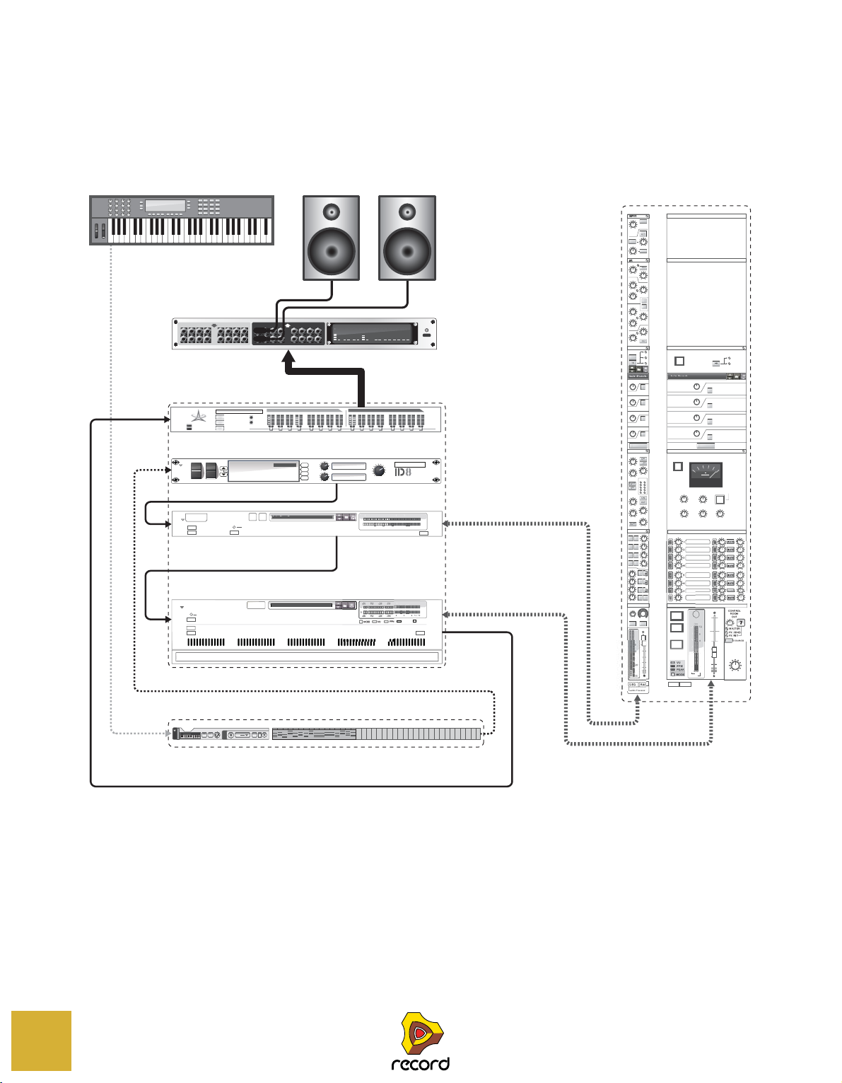
Instrument Track signal paths
INSERT
DYNAMICS
SEQ RACK
LEVEL LEVEL
1
2
3
4
PAN
FX SEND FX RETURN
Rotary 1
Button 1
Rotary 2
Button 2
Rotary 3
Button 3
Rotary 4
Button 4
EDIT INSERTS
DYN
2
6
VU
VU
2
5
0
8
0
MUTE
MUTE
MUTE
MUTE
DIM
-20dB
SOLO
ALL OFF
MUTE
ALL OFF
ON
BY
PASS
KEY
EXTERNAL
SIDECHAIN
ROUTING
Init Patch
5
6
7
8
MUTE
MUTE
MUTE
MUTE
LEVEL
CONTROL
ROOM
OUT
7
MASTER
FX SEND
FX RET
SOURCE
THRESHOLD
RATIO
ATTACK
RELEASE
MAKE-UP
L
Rec Source
External Routing
Bypass Insert FX
My Master Patch
D
Show Programmer
Show Insert FX
MODE
VU
PPM
PEAK
RESET
840
1 2 3 4 5 6 7 8 9 10 1112 13 14 15 16 1 2 3 4 5 6 7 8 9 10 1112 13 14 15 16
AUDIO INPUT AUDIO OUTPUT
ADV. MIDI DEVICE IN USE
MORE AUDIO I/O IN USE
REWIRE
AUDIO CARD
SHOW BIG METR
FIREWYRE 16x16 Audio Interf
8
4
840
FIREWYRE 16x16 AUDIO INTERFACE
N
A
T
- L -
- R -
- L -
- R -
POWER
1234 56 78 910111213141516
35689
Rack
MIDI In
MIDI Out from Master Keyboard
ID8 audio output signal via Mix Channel device
Mix Channel control
Master Section control
Output signal from Master Section device
Live and playback MIDI data from Instrument Track in sequencer
Sequencer
Main Mixer
Audio Interface
ID8 audio output signal
External Routing
Bypass Insert FX
Rec Source
Init Patch
Show Programmer
Show Insert FX
MUTE SOLO
L
8
4
0
-20VU
-56
284
0-10
-20VU-56
MIX CHAN...
PITCH MOD
VOLUME
Piano
Upright
Delay
Chorus
Dance
Vibes
Grand
A
B
C
D
instrument device
ID8 1
Rotary 1
Button 1
Rotary 2
Button 2
Rotary 3
Button 3
Rotary 4
Button 4
G
HF
HMF
Khz
Khz
SE
Khz
Khz
dB
dB
Q
LMF
LF
Khz
dB
Q
Khz
dB
RATIO
REL
RANGE
REL
THRES
HOLD
THRES
COMP/LIM
GATE/
EXP
EQ
DYN
INSERT
DYNAMICS
FADER
GE CL
L R
ON
BELL
HPF
INV
LPF
ON
FAST
FAST
KEY
ON
E
S/C
BYP
EDIT INSERTS
8
MUTE
SOLO
FX SEND
1
PRE
2
PRE
3
PRE
4
PRE
5
PRE
6
PRE
7
PRE
8
PRE
Init Patch
SEQ RACK
MIX CHAN...
ID8 1
S
S
When you’re recording and playing back audio from an instrument device, like the ID8 Instrument device, the audio
signal only has to travel only in one direction: from the Instrument device, via the hardware audio interface, to a
speaker system or similar. The figure below shows a schematic overview of the audio signal paths for an auto-routed
Instrument Track in Record:
PHA
AIN
AUDIO I
ASTER SECTION
TTM SERIES SUPERDIGITA
An Instrument Track signal path in Record
UDIO OU
IM -20dB
0-1
0
12
4
0
0
-5
6
12
1
2
76
AUDIO BASICS

General information about audio and computers
About latency
On any personal computer system, there is a delay between the moment you input a sound, or “tell” the hardware to
play a sound, and when you actually hear it. This delay is referred to as the “latency” of the design. This imposes a
problem for any system where you want real-time user input to affect the sound.
Why is there latency?
All audio applications receive and generate their audio in chunks. These chunks are then passed on to the audio card
where they are temporarily stored before being converted into regular audio signals. The storage place for these
chunks are called “buffers” (an analogy would be a bucket brigade, where a number of people each have a bucket,
and water is poured from one bucket to another to reach its final destination).
The smaller the buffers and the fewer they are, the more responsive the system will be (lower latency). The general
rules regarding the buffer size are these:
• A small buffer size reduces the latency (the time it takes for the audio to “travel” from the audio interface input(s) to the application and from the application to the audio interface output(s)).
However, a small buffer size also increases the DSP Load. Too small a buffer size setting could also make the
sound crackle and distort.
• A large buffer size reduces the DSP Load (allowing for more tracks to be played back simultaneously) and also
ensures good audio quality.
However, a large buffer size also increases the latency.
A high sample rate will also reduce the latency. However, this will also raise the demands on the computer and its
software. If the system can’t cope with moving the data to and from the buffers fast enough, there will be problems
that manifest themselves as glitches in audio playback.
To make things worse, audio playback is always competing with other activities on your computer. For example, a
buffer size that works perfectly under normal circumstances might be too small when you try to open files during
playback, switch over to another program while Record is playing or simply play back a very demanding song.
What is acceptable?
On a regular PC, the latency can vary quite a lot. This is an effect of the fact that computers and their operating systems were created for many purposes, not just for recording and playing back audio. For multimedia and games, a latency of a 100 ms might be perfectly acceptable, but for recording and playing back audio it is definitely not!
• PC audio cards running under Windows with a MME driver might at best give you a latency of around 160ms.
• The same card with a DirectX driver running under Windows provides at best around 40ms.
• A card specifically designed for low latency, with an ASIO driver under Windows, or a Core Audio driver under
Mac OS X, can usually give you figures as low as 2-3 ms. This is definitely good enough for audio applications.
That’s also why ASIO or Core Audio drivers are required to run Record.
Record’s built-in sequencer is not affected by latency
When Record’s sequencer is playing back a song, the timing between notes and audio is perfect! Once playback of a
Record pattern or song is up and running, latency isn’t a consideration at all. The computer clocks the audio between
the steps and does this with perfect quartz accuracy! The timing is immaculate!
AUDIO BASICS
77

ReWire and Latency
When you run Record as a ReWire slave, it is the other program, the ReWire master, that is responsible for actually
rendering the audio and playing it back via the audio card. It means that any latency is present in the ReWire master.
! When Record runs as a ReWire slave, what audio hardware you have, what audio driver you use, and the audio
settings you have made in the Preferences dialog are of no importance at all! All audio hardware settings are
then instead made in the ReWire host application.
! Note, however, that you may have to adjust the “External Sync Offset” in Preferences if Record is synced via
MIDI from the host application (see “Synchronization considerations”).
For information on ReWire, see “ReWire”.
Reducing latency
There are a few general methods for making sure latency is as low as possible:
D Make sure you are using the latest version of the drivers for your hardware audio interface.
D Adjust the Sample Rate and Buffer Size parameters as described in “Audio settings”.
D Remove unnecessary background tasks on your computer.
This might be any background utility you have installed as well as networking, background internet activities etc.
D Optimize your songs.
You might run into situations where you have to raise the Output Latency setting to be able to play back a very demanding song on your computer. Another option would be to actually optimize the song. See “Optimizing Perfor-
mance” for details.
D Get a better audio interface.
This is only required if you find that you need to increase Output Latency because your audio card can’t really cope
with the songs you try to play.
D Get a faster computer.
This is only required if you find that you need to increase Output Latency because your computer can’t really cope
with the songs you try to play.
About processors
When you run Record, the clock speed of the processor is a major factor determining how many audio tracks and devices you can use at the same time.
If you plan to buy a computer specifically for Record, you could play it safe and choose a computer with at least an Intel P4, or equivalent AMD processor, running at 2.0 GHz or faster. MultiCore processors will give better performance
and are highly recommended.
About RAM
Another important performance factor is the amount of installed RAM in the computer. Generally, one could say: the
more the better, especially if you’re running several applications simultaneously. To run Record, a minimum of 1 GB
RAM is required, but more is recommended for even better performance.
78
AUDIO BASICS

Mac specific information
About using the built-in audio inputs and outputs
All Mac models come with a built-in audio interface, providing stereo input and output jacks (and in some cases a
built-in microphone). Depending on your needs, the quality of these inputs and outputs may be fully sufficient for use
with Record. However, in Mac OS X 10.4 the system presents the built-in inputs and outputs as two or three individual audio devices. This means that, by default, you can only select the "Built-in Output" option in Record's Preferences. This works fine for playback, but since you get no inputs at all, you cannot record audio.
To get access to both built-in inputs and outputs in Mac OS X 10.4, you need to create an "Aggregate Device", combining inputs and outputs into one "virtual" audio device. This is done in the Aggregate Device Editor.
! Although Aggregate Devices can be used, regular audio devices with both inputs and outputs have proven to
be more reliable and allow lower latencies. Therefore, we recommend using external audio hardware with
good Core Audio drivers instead.
! In Mac OS X 10.5 and later, the Core Audio drivers support combinations of audio inputs and outputs. If you
run Record under Mac OS X 10.5 or later you do not have to create an Aggregate Device!
Proceed as follows to create an Aggregate Device:
1. In OS X, open “Audio MIDI Setup” in the “Utilities” folder in “Applications”.
2. Select “Open Aggregate Device Editor” from the Audio menu.
The Aggregate Device Editor
3. In the Aggregate Device Editor, click the “+” button to create a new aggregate device.
If you like, you can rename your new aggregate device.
4. Place a tick in the “Use” check boxes for each of the Audio Devices you want to use.
For example, if you want to use the “Built-in Line Input” and “Built-in Output”, tick these two boxes.
! If you want to use the “Built-in Microphone” together with the “Built-in Output”, note that there might be audio
feedback loops if you use the computer’s internal speakers or external speaker close to the built-in microphone! We recommend NOT using the “Built-in Microphone” option, partly because of the feedback loop problem and partly because of the limited audio quality of the built-in microphone.
5. Click “Done” to finish and exit the Aggregate Device Editor.
6. In the Audio MIDI Setup window, choose the Aggregate Device you just created by selecting it in the “Default
Input” and “Default Output” drop-down lists respectively.
7. Select your Aggregate Device from the “Properties For” drop-down list and set up the “Format” in the dropdown lists that appear in the “Audio Input” and “Audio Output” sections at the bottom of the window.
D Choose “2ch-24bit” for best audio resolution.
8. When you’re done, exit the Audio MIDI Setup.
! If Record was running while you created you new aggregate device, you’ll have to restart Record for the new
aggregate to be available in the “Audio Card” drop-down list on the “Audio” page in the Preferences dialog.
AUDIO BASICS
79

80
AUDIO BASICS

Chapter
Sequencer Functions
5

About this chapter
Edit/Arrangement
Pane
Toolbar
Track
List
Ruler
Inspector (context sensitive)
Audio Clips
Note Clips
Tracks
Edit Mode and Song/Blocks View buttons
Track Navigator
Transport Panel
Song Navigator
Lanes
Automation Clips
Blocks On/Off
Blocks Track
This chapter describes the layout and general functions of the main sequencer. Recording, editing clips and events,
arranging and working with Blocks in the sequencer are described in detail in the chapters “Recording in the Se-
quencer”, “Audio Editing in the Sequencer”, “Note and Automation Editing”, “Arranging in the Sequencer” and “Working with Blocks in the Sequencer”.
Introduction
The sequencer is where you record your songs. The sequencer can be used to record audio tracks as well as instrument tracks, performance controllers, parameter automation and pattern automation (Record+Reason). You can also
arrange your songs, or parts of your songs, in Blocks. In Blocks mode you can build complete “sections” - consisting
of a desired number of bars and tracks - that can be reused throughout the song. This chapter mainly describes the
Song View and Edit Mode. Functions specific to Blocks and the Blocks View are described in the separate chapter
“Working with Blocks in the Sequencer”.
Sequencer area overview
82
SEQUENCER FUNCTIONS

Song View and Edit Mode
If the Blocks button on the Transport Panel is off, only the Edit Mode button is shown in the Toolbar. If the Blocks
button on the Transport Panel is on, the Song View and Block View buttons also appear in the Toolbar. The Song
View is the “normal view” where you are working with your song arrangement. This mode gives a good overview of
the content of the tracks in your song.
If the Blocks button on the Transport Panel is activated, you can click the Block View button to enter Block View. In
Block View you arrange the clips you want to include in specific Blocks (see “Working with Blocks in the Se-
quencer”). Edit Mode is where you edit the contents of the clips in your song. In Edit Mode the Edit Pane shows de-
tailed information about the content of one track (see “Tracks overview”), or lane (see “Lanes overview”) at a time and
you can edit the events in individual clips (see “Clips overview”).
q When you open a note or audio clip by double-clicking it in Song View or Block View, the sequencer automat-
ically switches to Edit Mode. However, if you double-click a parameter automation clip, it opens up for editing
directly in the Song View or Block View.
Song View
In the Song View, all clips on all tracks can be viewed. Use this mode to get an overview of your arrangement, and
when you want to perform clip-based editing such as rearranging whole sections of your song, etc.
! Note that when the Blocks button on the Transport Panel is off, there is no separate Song View button in the
Toolbar, simply because Song View is the default view here.
SEQUENCER FUNCTIONS
83

Edit Mode
In Edit Mode, you get a close-up look at the recordings on a track. In Edit Mode, the Edit Pane can be divided into
several horizontal edit rows, showing different types of events (notes, velocity, audio, parameter automation, etc.). This
is the view mode of choice for fine editing the content of your recorded clips, and for drawing notes, performance
controllers and other events manually.
Toolbar overview
The sequencer Toolbar features various sequencer editing tools as well as the Snap function. The tools can be used
in both Edit Mode and the Song/Block Views, with slightly different purposes in the respective modes. See “Toolbar
details” for details about each tool.
Track List overview
To the left in the sequencer, all tracks are listed in the Track List. Each track in the sequencer is associated with a
specific device in the rack. By clicking on a device icon in the Track List you automatically set Master Keyboard Input
(see “Setting Master Keyboard Input”) to the corresponding device in the rack for playing and/or recording.
84
SEQUENCER FUNCTIONS

Tracks overview
Tracks
Lanes
Most rack devices in a song automatically get their own dedicated track in the sequencer when you create the device.
Each track can feature one or several lanes on which audio, note, performance controller, pattern (Record+Reason)
and parameter automation events can be recorded - in clips. See “Track details” for more details about tracks.
! If the Blocks button on the Transport Panel is on, the Blocks Track is also shown at the top in the Track List.
Lanes overview
Each track consists of one (default) or several parallel lanes. The lanes can contain clips that feature note events or
audio recordings, depending on track type. A track can also feature automation lanes that contain clips with parameter automation events - or pattern automation for pattern based devices (Record+Reason). See “Lane details” for
more details about lanes.
SEQUENCER FUNCTIONS
85

Clips overview
Audio Clips
Note Clips
Automation Clips
Note, audio, performance controller, pattern (Record+Reason) and parameter automation events are always contained in clips. A clip is basically a “container” for recorded data. Audio clips are displayed in the Edit/Arrange Pane
as a rectangular box with one or two graphical audio waves inside (mono or stereo). Note events are displayed in a
“piano roll” fashion in the clip. Performance controllers and parameter automation events are displayed as continuous
lines, and pattern events (Record+Reason) are displayed as repeated rectangles in the clips. See “Clip basics” for information about the different clip types.
Inspector overview
The context sensitive Inspector shows the properties of whatever is currently selected in the sequencer: clips, notes,
automation events, audio comp rows and cuts etc. The properties of the selected item can be edited by changing the
values in the various displays. See “About the Inspector” for more info.
Ruler overview
The Ruler is the song’s “time line”, measured in bars. In the Ruler, the Song Position Pointer indicates the current position in the song, i.e. in which bar the song is, or will begin, playing. The Ruler also shows the Left and Right Loop Locators as well as the Song End Marker. See “Ruler details” for more details.
Edit/Arrangement Pane overview
The big center section of the sequencer is called the Edit/Arrangement Pane. This is where all recorded events reside in clips - on one or more lanes on the respective track.
86
SEQUENCER FUNCTIONS

Track Navigator overview
To the far right in the sequencer is the Track Navigator. With the Track Navigator you can scroll vertically in the Edit/
Arrange Pane. In the Track Navigator, you can also see which track is selected (dark background color) and which
track has Master keyboard Input (red frame around the device icon). See “Scrolling” and “Zooming in the Sequencer”
for more details.
Song Navigator overview
Below the Edit/Arrangement Pane is the Song Navigator. With the Song Navigator you can scroll and zoom horizontally on the Edit/Arrangement Pane. The Song Navigator also features indicators for the Ruler’s Loop Locators, Song
Position Pointer and Song End Marker. In the Song Navigator, all clips on all lanes are displayed as colored lines, indicating their positions in the song. See “Scrolling” and “Zooming in the Sequencer” for more details.
Transport Panel overview
The Transport Panel features the sequencer transport controls (Rewind, Fast Forward, Stop, Play and Record) as well
as controls for Tempo, Time Signature, Position, Time and Loop Locator placements and some other functions. See
“Transport Panel details” for more details.
SEQUENCER FUNCTIONS
87
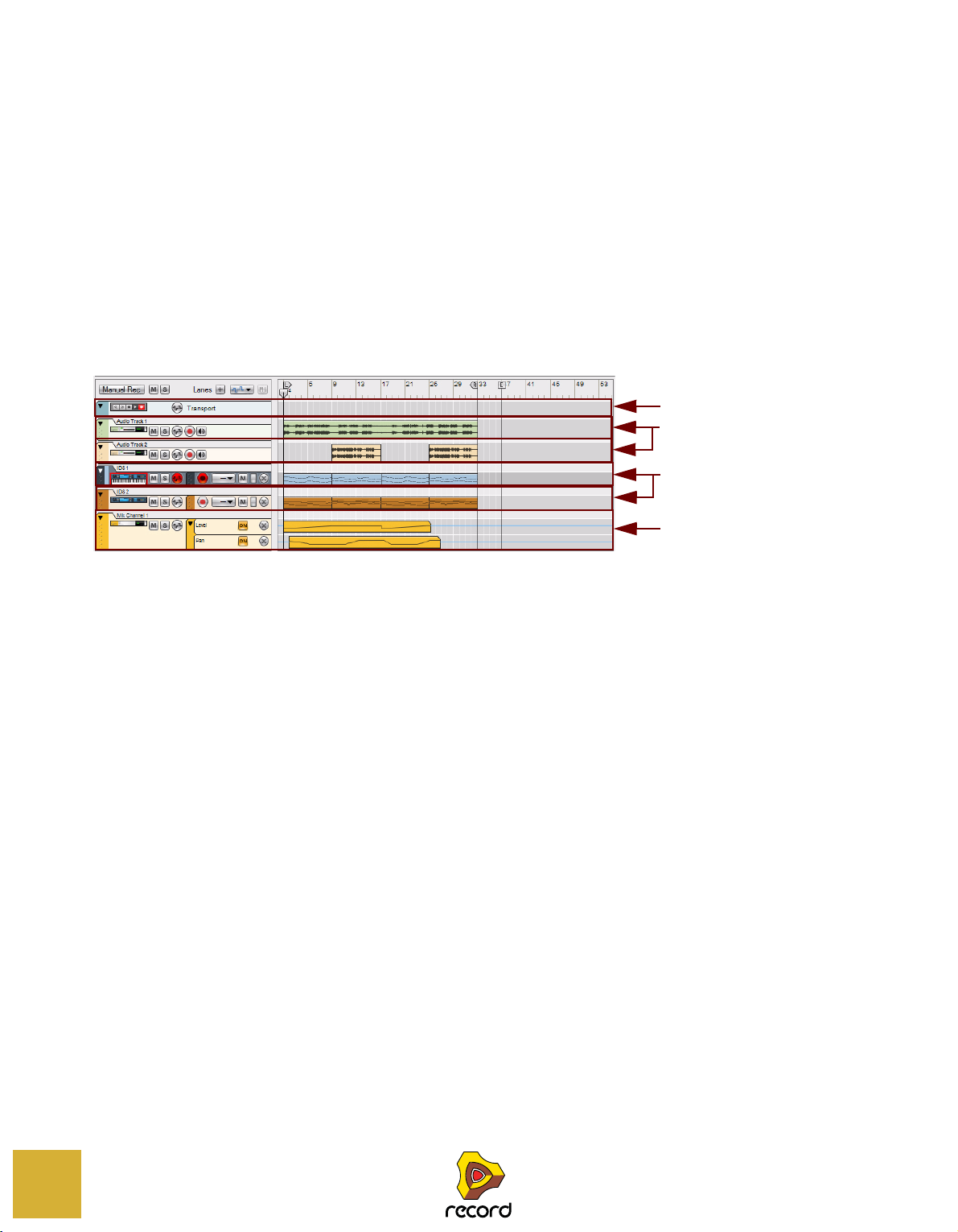
Track details
Transport Track
Audio Tracks
Instrument Tracks
Automation Track
Track definition
The tracks in the sequencer are where you record your audio, note and automation to create your songs. A track is always associated with a device in the rack (except for the Transport track and Blocks track). An icon with a picture of
the associated device is shown in the Track List on the left hand side in the sequencer. In the Track List, the name of
the associated device is shown, as well as icons and buttons related to the specific track. Each track can incorporate
various lane types (depending on track type). To the right of the Track List - on the Edit/Arrangement pane - each
track has its own dedicated area for recorded events.
In the picture below, six sequencer tracks are shown. From the top down are the Transport Track (which is always
present and cannot be moved or deleted), two audio tracks, two instrument tracks associated with one ID8 instrument device each, and one automation track for a Mix Channel strip.
88
SEQUENCER FUNCTIONS
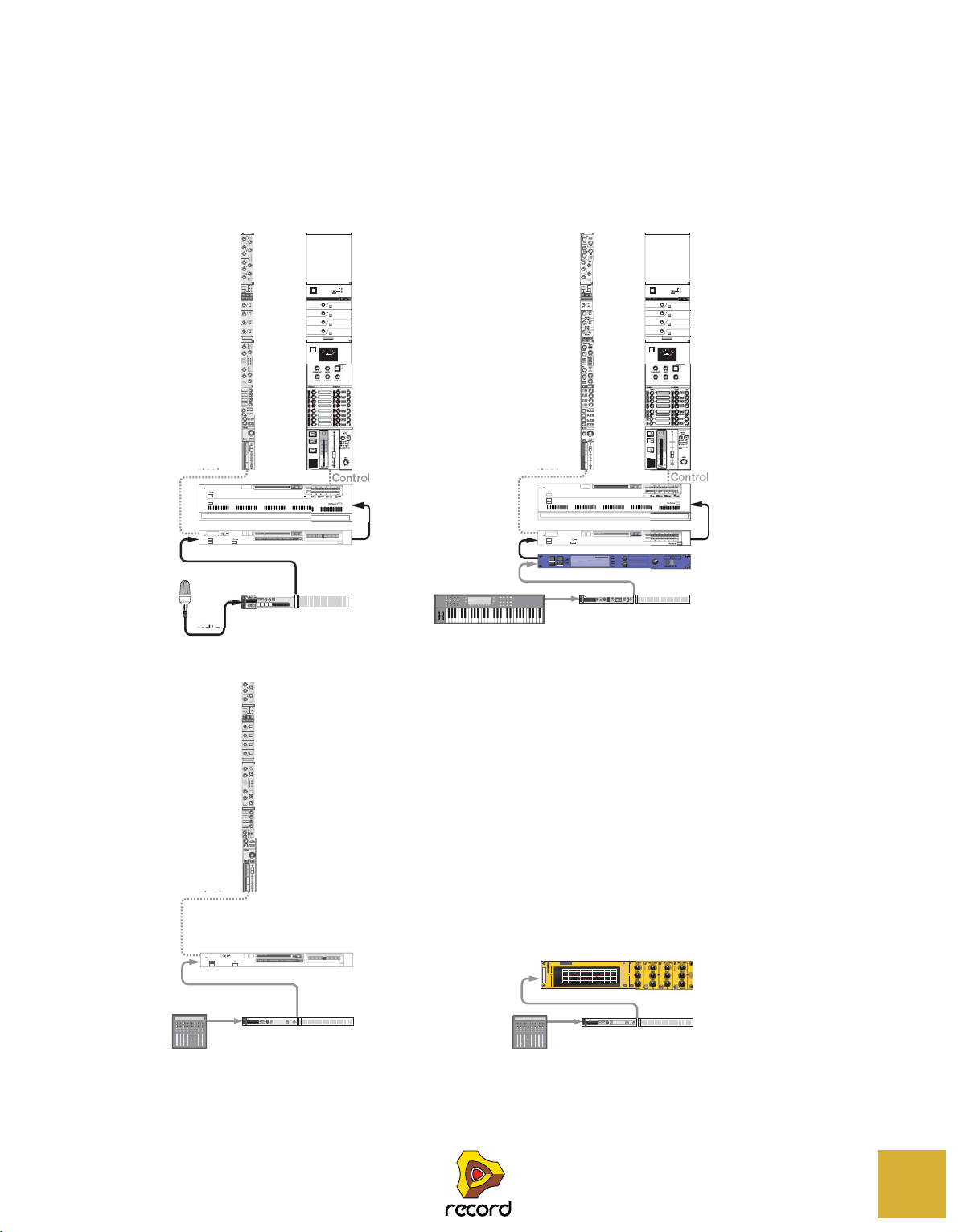
The relationship between the track, the rack and the Main Mixer
Audio Track
Instrument Track
Automation Track (of channel strip parameters)
Automation Track (of device parameters)
Rotary 1
Button 1
Rotary 2
Button 2
Rotary 3
Button 3
Rotary 4
Button 4
LF
Khz
dB
Q
Khz
dB
RATIO
REL
RANGE
REL
THRES
HOLD
THRES
COMP/LIM
GATE/
EXP
EQ
DYN
INSERT
DYNAMICS
FADER
GECL
L R
ON
ON
EXP
FAST
FAST
BYP
EDIT INSERTS
MUTE
SOLO
FX SEND
1
PRE
2
PRE
3
PRE
4
PRE
5
PRE
6
PRE
7
PRE
8
PRE
Init Patch
External Routing
Bypass Insert FX
Rec Source
Init Patch
Frippe FW ASIO Interfaze Analog In 1
MUTE SOLO
Show Programmer
Stretch Type
Show Insert FX
0
VU-56
DISK CHA...
Mix Channel 1
S
S
FX2 Send On
ON
ON
MIDI
MIDI
Control
PITCH MOD
VOLUME
Piano
Upright
Delay
Chorus
Dance
Vibes
Grand
A
B
C
D
instrument device
ID8 2
External Routing
Bypass Insert FX
Rec Source
Init Patch
Frippe FW ASIO Interfaze Analog In 1
MUTE SOLO
Show Programmer
Stretch Type
Show Insert FX
1080-10
-20VU-56
AUDIO TR...
External Routing
Bypass Insert FX
Init Patch
Show Programmer
Show Insert FX
MUTE SOLO
VU
-56
VU
-56
MIX CHAN...
INSERT
DYNAMICS
1
2
3
4
PAN
FX SEND FX RETURN
Rotary 1
Button 1
Rotary 2
Button 2
Rotary 3
Button 3
Rotary 4
Button 4
EDIT INSERTS
DYN
MUTE
MUTE
MUTE
MUTE
DIM
-20dB
SOLO
ALL OFF
MUTE
ALL OFF
ON
BY
PASS
KEY
EXTERNAL
SIDECHAIN
ROUTING
Init Patch
5
6
7
8
MUTE
MUTE
MUTE
MUTE
LEVEL
CONTROL
ROOM
OUT
7
MASTER
FX SEND
FX RET
SOURCE
THRESHOLD
RATIO
ATTACK
RELEASE
MAKE-UP
INSERT
DYNAMICS
LEVEL
1
2
3
4
PAN
FX SEND FX RETURN
Rotary 1
Button 1
Rotary 2
Button 2
Rotary 3
Button 3
Rotary 4
Button 4
EDIT INSERTS
DYN
MUTE
MUTE
MUTE
MUTE
DIM
-20dB
SOLO
ALL OFF
MUTE
ALL OFF
ON
BY
PASS
EXTERNAL
SIDECHAIN
ROUTING
Init Patch
5
6
7
8
MUTE
MUTE
MUTE
MUTE
LEVEL
CONTROL
ROOM
OUT
7
MASTER
FX SEND
FX RET
SOURCE
THRESHOLD
RATIO
ATTACK
RELEASE
MAKE-UP
Rotary 1
Button 1
Rotary 2
Button 2
Rotary 3
Button 3
Rotary 4
Button 4
HF
HMF
Khz
Khz
dB
dB
Q
LMF
LF
Khz
dB
Q
Khz
dB
RATIO
REL
THRES
HOLD
THRES
COMP/LIM
GATE/
EXP
EQ
DYN
INSERT
DYNAMICS
FADER
GECL
L R
E
BYP
EDIT INSERTS
MUTE
SOLO
FX SEND
1
PRE
2
PRE
3
PRE
4
PRE
5
PRE
6
PRE
7
PRE
8
PRE
Init Patch
Rotary 1
Button 1
Rotary 2
Button 2
Rotary 3
Button 3
Rotary 4
Button 4
HF
HMF
Khz
Khz
dB
dB
Q
LMF
LF
Khz
dB
Q
Khz
dB
RATIO
REL
RANGE
REL
THRES
HOLD
THRES
COMP/LIM
GATE/
EXP
EQ
DYN
INSERT
DYNAMICS
FADER
GECL
L R
ON
ON
BELL
ELL
BELL
ON
EXP
FAST
FAST
O
E
BYP
EDIT INSERTS
MUTE
SOLO
FX SEND
1
PRE
2
PRE
3
PRE
4
PRE
5
PRE
6
PRE
7
PRE
8
PRE
Init Patch
Disk Channel 1
S
S
ID8 1
M
S
S
M
Rec Source
External Routing
Bypass Insert FX
My Master Patch
D
Show Programmer
Show Insert FX
MODE
VU
PPM
PEAK
RESET
VU
-56
VU
-56
VU
-56
MAS
ON
T
Rec Source
External Routing
Bypass Insert FX
My Master Patch
0dB
Show Programmer
Show Insert FX
MODE
VU
-56
L
V
6
VU
-56
Audio
Audio
Audio
Audio
Audio
MIDI
MIDI
Control
Control
Control
Control
H
C/S
Q
Bypass
On
Off
Equal
LO
S
O
CUT
MClass
FREQ
GAIN
Q
FREQ
GAIN
Q
FREQ
30-600Hz 30Hz-20kHz 30Hz-20kHz30Hx
GAIN
SLOPE
FREQ
3kHz-18kHz
GAIN
SLOPE
18 dB
12 dB
6 dB
0 dB
-6 dB
-12 dB
-18 dB
39Hz 78Hz 156Hz 312Hz 625Hz 1kHz 2.2kHz 4kHz 8kHz 16kHz
M EQ 1
Mix Channel 1
S
S
FX2 Send On
ON
ON
MIDI
MIDI
A track in the sequencer is always associated with a device in the rack; i.e. there can never be a sequencer track without an associated rack device (except for the Transport track and Blocks track). Audio Track devices and Mix Channel devices in the rack also have their corresponding Channel strips in the Main Mixer. Mixer Channel strips can be
considered “remote controls” for their corresponding rack devices. Depending on track type, the signal chain differs
somewhat. The picture below shows the signal flow in four scenarios with three different track types:
N
MASTER SECTION
IM -20dB
TTM SERIES SUPERDIGITAL
-
TER SECTI
TM SERIES SUPERDIGITAL
1210840-10-2
DIM -2
izer
IGH DEFINITION PARAMETRI
U-5
L
HELVING E
HELF
SEQUENCER FUNCTIONS
89

Audio track relationships
Audio Track
Audio Track device
Audio Track Channel strip
Control
Audio and mixer
automation
An audio track is always associated with an Audio Track device in the rack and its corresponding Audio Track channel strip in the Main Mixer. An Audio Track device can also house insert effects.
In the figure above, the audio track is associated with the Audio Track device in the rack,
which in turn is controlled from the Audio Track channel strip in the Main Mixer. The audio track
features recorded audio and mixer automation.
90
SEQUENCER FUNCTIONS

Instrument track relationships
The ID8 Track
Audio
ID8 Mix Channel device
ID8 Mix Channel strip
Control
MIDI and
parameter
automation
ID8 device
An instrument track is always associated with an instrument device in the rack. The instrument device in the rack is,
in most situations, connected to a Mix Channel device in the rack. The Mix Channel device in the rack is controlled
from the corresponding channel strip in the Main Mixer. A Mix Channel device can also house insert effects.
In the figure above, the ID8 track is associated with the ID8 instrument device in the rack. The ID8 instrument
device is connected to the ID8 Mix Channel device in the rack, which in turn is controlled from the ID8
channel strip in the Main Mixer. The ID8 track features recorded MIDI notes and parameter automation.
Note that when you create an instrument, the connected Mix Channel device doesn’t automatically get a track in the
sequencer. If you want to record Mixer Channel automation, you have to first create a separate sequencer track for
the Mix Channel device. See “Automation (non-instrument) track relationships”.
SEQUENCER FUNCTIONS
91

Automation (non-instrument) track relationships
The Mix Channel Automation Track
ID8 Mix Channel device
Mix Channel strip
Control
Parameter
automation
The Equalizer
Automation Track
The Equalizer device
MIDI
A pure automation track is always associated with a “non-instrument” device, i.e. a device which can’t receive MIDI
Note
information. Consequently, an automation track can only consist of parameter automation lanes. Examples of
non-instrument devices are Mix Channel devices with their corresponding Mix Channel strips, effect devices, mixer
devices and Spider Merger & Splitter devices. The picture below shows an example with an automated Mix Channel:
92
In the figure above, the Mix Channel automation track is associated with the Mix Channel device
in the rack, which in turn is controlled from the channel strip in the Main Mixer.
The picture below shows an example with an automated MClass Equalizer device. Note that no mixer channel strip is
involved in this situation since the automation only concerns a non-instrument device and not any Mix Channel device:
In the figure above, the Equalizer automation track is associated with the Equalizer device in the rack.
SEQUENCER FUNCTIONS

Master Keyboard Input
The standard way of routing MIDI from a connected MIDI master keyboard or control surface to a device in the rack
is to set the Master Keyboard Input in the sequencer. When MIDI is routed to a selected track in the sequencer, the
notes and controller data are automatically echoed to the associated device in the rack.
• Setting Master Keyboard Input to an instrument track is necessary if you want to play notes on an instrument
device from your MIDI master keyboard (and control the instrument device parameters via MIDI).
By locking additional MIDI keyboards to separate devices in the rack, you will be able to play and record on several
sequencer tracks simultaneously, see “Locking a surface”.
• Setting Master Keyboard Input to an audio track is only necessary if you want to control the Main Mixer chan-
nel strip parameters via MIDI.
• Setting Master Keyboard Input to a “non-instrument” (parameter automation only) track is only necessary if
you want to control the device’s parameters via MIDI.
Besides the standard routing described above, it’s also possible to lock certain rack devices to specific control surfaces. See “Locking a surface” for more details.
! If you have several MIDI keyboards/control surfaces locked to individual devices in the rack, it is possible to
control and record on several tracks simultaneously!
Setting Master Keyboard Input
D To set Master Keyboard Input to a track and its associated device, click the device icon in the Track List.
Master Keyboard Input set to an instrument track
Master Keyboard Input set to an audio track
The device icon gets a keyboard symbol below it and a red border, indicating that the track and associated device
has Master Keyboard Input. The track and device will now respond to incoming MIDI data from a connected MIDI
keyboard/control surface. By default, setting Master Keyboard Input also automatically selects the track, which is
indicated by the darker color of the track in the Track List.
It’s also possible to set Master Keyboard Input and track selection independently from each other by selecting
“Separated” on the “Keyboards and Control Surfaces” page in Preferences - see “Preferences – Keyboards and
Control Surfaces”.
• Only one track at a time can have Master Keyboard Input. However, if you have locked additional MIDI key-
boards to specific devices in the rack via Remote (see “Locking a surface”), you will be able to play and record
these together with the track that has Master Keyboard Input.
SEQUENCER FUNCTIONS
93

The relationship between tracks, lanes, clips and events
Track
Lane
Lane
Lane
Lane
Clip
Clip
Clip
Clip
Note Events
A track is the top level in the sequencer Track List hierarchy. A track can consist of one or several parallel lanes. A
lane can contain clips, which in turn can contain audio recordings, note events, performance controller events, parameter automation events or pattern events (Record+Reason), depending on track type.
An instrument track with four note lanes featuring clips with note events.
• A device in the rack can never have more than one track in the sequencer.
• A clip is a “container” for various types of events (audio recordings, note, performance controller, parameter
automation or pattern (Record+Reason) events).
Track types
These are the different track types:
• The Blocks track.
The Blocks track is present at the top of the Track List only when the Blocks button on the transport Panel is on.
On the Blocks track you can create Block Automation clips to decide which Blocks should play back. Refer to
“Working with Blocks in the Sequencer” for more information about the Blocks feature.
• The Transport track.
The Transport track is always present at the top of the Track List and cannot be moved or deleted. The Transport
Track can have a maximum of two lanes: one containing time signature automation, and the other containing
tempo automation. See “Automating time signature” and “Editing tempo automation” for more details.
94
SEQUENCER FUNCTIONS

• Audio tracks
An audio track can only have a single audio lane containing clips with mono or stereo audio recordings. However,
each audio clip can contain several recordings, i.e. different "takes". You can view and comp these takes in Edit
Mode. See “Audio Editing in the Sequencer” for more details. An audio track can also have parameter automation
lanes containing automation for the Audio Track Channel strip parameters in the Main Mixer.
• Instrument tracks
Devices that can receive MIDI notes, such as the Combinator device, will automatically be assigned a record enabled track when created. On an instrument track you can create a number of separate note lanes that can incorporate clips containing a combination of note and performance controller events. Multiple lanes are perfect if you,
for example, are recording a drum track and want to record each drum sound on a separate lane. An instrument
track can also have a number of parameter automation lanes that can contain clips with instrument parameter automation events.
• Parameter automation (“non-instrument”) tracks
Tracks for devices that do not receive MIDI note data (e.g. effects and mixer devices and mixer channels in the
Main Mixer) can only contain parameter automation lanes. These “non-instrument” devices are not automatically
assigned a track when created. To automate parameters for non-instrument devices you need to manually create
a track for these. The number of available lanes is limited by the number of parameters of each device. There can
be one lane for each automatable parameter in the device.
SEQUENCER FUNCTIONS
95

Track List elements
Device Icons
with names
Track Mute buttons
Track Solo buttons
Record Enable Parameter Automation buttons
Note Lanes
Parameter Automation
Lanes
Parameter Automation
Lanes
Parameter Automation
Lanes
Transport Track
Audio Track
Instrument Track
Automation Track
In the picture below, a Track List with four different tracks is shown. From the top down are the Transport Track
(which is always present and cannot be moved or deleted), an Audio Track associated with an Audio Track device, an
Instrument Track associated with an ID8 Instrument device and an Automation Track associated with the Mix Channel device connected to the ID8 Instrument device.
The Transport Track in the picture features two parameter Automation Lanes (for Time Signature and Tempo) that
have been manually created for the track. The audio track features only a single audio lane. The ID8 1 track features
four note lanes and has two parameter automation lanes added. The Mix Channel 1 track is associated with the Mix
Channel 1 device and has three parameter automation lanes added.
96
Depending on track type, the elements shown in the Track List can vary. The only common element for all track types
is the "Record Enable Parameter Automation" button which should be enabled when you want to record parameter
automation for the associated device. This and the other track elements will be described in detail later in this chapter.
SEQUENCER FUNCTIONS

Creating tracks
Audio Track
Audio Track device
Audio Track Channel strip
Control
Audio and mixer
automation
Creating an audio track
An audio track can be created as follows:
1. Hold down [Ctrl](Win) or [Cmd](Mac) and press [T]. Alternatively, select “Create Audio Track” from the “Cre-
ate” menu or from the context menu in the Track List, rack or Main Mixer.
D Alternatively, click the “Create Audio Track” button on the “Devices” tab in the Tool Window.
2. An audio track is created in the sequencer and the associated Audio Track device is created in the rack. The
Audio Track device’s channel strip is created in the Main Mixer.
By default, the audio track is set up in mono. You can easily change to stereo by selecting “Stereo Input” in the
“Audio Input” drop-down list - see “Selecting audio input(s) and defining mono or stereo”. If you select “Stereo In-
put”, the Audio Track channel strip in the Main Mixer automatically switches to a stereo channel.
SEQUENCER FUNCTIONS
97

Creating an instrument track
The ID8 Track
Audio
ID8 Mix Channel device
ID8 Mix Channel strip
Control
MIDI and
parameter
automation
ID8 device
To create an instrument track, you need only create the instrument device. An instrument track is automatically created when you create a device which can receive MIDI notes:
1. Select desired instrument type from the “Create” menu.
Alternatively, to select an Instrument patch and automatically load the patch into the appropriate device type, hold
down [Ctrl](Win) or [Cmd](Mac) and press [I], or select “Create Instrument” from the “Create” menu to bring up the
Patch Browser. Under Windows, you can also press [Insert] to open the Patch Browser. In the Patch Browser you
can select and preview patches before loading them into the instrument.
D Alternatively, drag and drop or double-click the desired instrument device from the “Device Palette” tab on the
Tool Window. Or, to bring up the Patch Browser, click the “Create Instrument” button on the “Device Palette”
tab.
2. An instrument device is created in the rack and the associated track is automatically created in the sequencer.
In addition, a Mix Channel device for the instrument is automatically created in the rack and its channel strip is created in the Main Mixer. All devices are automatically connected. The Mix Channel device automatically adapts its
inputs to the created instrument type - if the instrument is in mono, the Mix Channel device will be in mono, and if
the instrument has stereo outputs, the Mix Channel device will be in stereo.
98
! Note that no automation track is created for the Mix Channel device. This has to be manually created if you
want to automate any of the Mix Channel strip parameters (see “Creating a parameter automation track for a
non-instrument device”).
SEQUENCER FUNCTIONS

Creating a parameter automation track for a non-instrument device
RV7000 device
RV7000 device
TheRV7000 Automation Track
For non-instrument devices, such as effects devices and Mix Channel devices, you need to manually create a track if
you want to record parameter automation. You can do that either by following the description below or by following
either of the two last descriptions in “Creating/adding parameter automation lanes”.
The track creation procedure described below also applies if you have manually deleted a track for an instrument device or an Audio Track device and want to create a new track for the device:
1. Select the device by clicking on it in the rack.
A border around a device in the Rack indicates that it has been selected.
2. Select ”Create Track for (name of device)” from the Edit menu or the device context menu.
! Note that if a track already exists for the device, this menu item will not be available - a device can only have
one track.
• The new track will be automatically associated with the device and will get the same name as the device.
D Another way of creating a parameter automation track is by holding [Alt](Win) or [Option](Mac) and clicking
on a parameter on the device panel. Alternatively, select “Edit Automation” from the parameter context menu.
q If you press [Alt](Win) or [Option](Mac) when you create a non-instrument device, this will automatically create
an associated automation track for the device.
SEQUENCER FUNCTIONS
99

Short-cut for creating a Mix Channel track or Audio track
A faster way of creating a track for a Mix Channel device, or to create a new audio track (if you deleted the original
one), is to go via the corresponding mixer channel strips in the Main Mixer:
1. Scroll to the Main Mixer and locate the channel strip you want to create a track for.
2. [Shift]-click the SEQ (Goto Sequencer Track) button at the bottom of the channel strip.
A new track will be automatically created in the sequencer for the selected channel strip.
! If a track should already exist for the selected channel strip, [Shift]-clicking the SEQ (Goto Sequencer Track)
button will only scroll the corresponding sequencer track into view, not create any new track.
Selecting tracks
D Select a track by clicking on it in the Track List.
A selected track gets a darker color.
q Selecting a track in the sequencer will automatically scroll the corresponding device into view in the rack.
• Selecting an audio track will set Edit Focus to its channel strip in the Main Mixer.
• Selecting another type of track (e.g. an instrument track) will set Edit Focus to the Mix Channel belonging to
that device group.
See “About Device Groups” for information about device groups.
D You can also select the next or previous track in the Track List list by using the up and down arrow keys on the
computer keyboard.
! By default, selecting a track will automatically set Master Keyboard Input to that track. If you’d rather select
tracks independent of the Master Keyboard Input selection, select “Separated” mode in the Preferences menu
(“Keyboards and Control Surfaces” page). In “Separated” mode, you can select another track without automatically changing Master Keyboard Input. To change Master Keyboard Input, click the device icon on the desired track in the Track List.
D It is possible to select several tracks by using standard [Shift], or [Ctrl](Win) or [Cmd](Mac), selection tech-
niques.
This allows you to e.g. move or delete several tracks in one go.
100
SEQUENCER FUNCTIONS
 Loading...