

Page 1

Operation Manual
Page 2
Page 3

TABLE OF CONTENTS
Page 4

5 The Sequencer
6 Recording
10 Copying REX loops and Patterns to Sequencer
Tracks
12 Editing - About Snap
13 Editing in the Arrange View
16 Using Groups
19 The Edit View
28 Quantizing
29 The Change Events Dialog
31 Importing and Exporting MIDI Files
33 Routing Audio and CV
34 About the various signals that can be routed
34 About Cables
35 Automatic Routing
36 Manual Routing
37 Using CV and Gate
39 Routing MIDI to Reason
40 About the Various MIDI Inputs
41 Sending MIDI Data to Reason
43 Controlling Devices directly via MIDI
45 Using Reason as a ReWire Slave
46 About this Chapter
46 Why use Reason with ReWire?
46 Introducing ReWire!
47 Preparations for Using ReWire - Macintosh only
47 Launching and Quitting
48 Steinberg Cubase VST
50 Emagic Logic Audio
51 Mark of the Unicorn Digital Performer
52 Using the Transport and Tempo Controls
52 MIDI Control With ReWire
52 Converting ReWire Channels to Audio Tracks
52 Synchronization
53 MIDI and Keyboard Remote Control
54 Introduction
54 MIDI Remote Mapping
57 Keyboard Remote
58 Saving Remote Setups
59 Synchronization
60 ReWire users – Read This!
60 What is Synchronization and MIDI Clock?
60 Slaving Reason to an External Device
61 Slaving Reason to Another Program on the Same
Computer
62 MacOS: Slaving Reason to a non-OMS Program
63 Synchronization Considerations
2
TABLE OF CONTENTS
Page 5
65 Optimizing Performance
66 Introduction
66 Optimization and Output Latency
67 Optimizing Your Computer System
67 Optimizing Songs
69 Songs and Memory Requirements
71 Transport Panel
72 Overview
99 Subtractor Synthesizer
100 Introduction
100 The Oscillator Section
106 The Filter Section
110 Envelopes - General
112 LFO Section
114 Play Parameters
116 External Modulation
117 Connections
77 Reason Hardware Interface
78 Introduction
78 MIDI In Device
79 Audio Out
81 The Mixer
82 Introduction
82 The Channel Strip
84 The Mixer Signal Flow
84 The Auxiliary Return Section
84 The Master Fader
85 Connections
86 Chaining Mixers
87 Redrum
88 Introduction
88 About File Formats
89 Using Patches
90 Programming Patterns
93 Redrum Parameters
96 Using Redrum as a Sound Module
97 Connections
119 NN-19 Digital Sampler
120 Introduction
120 General Sampling Principles
121 About Audio File Formats
122 About Key Zones and Samples
125 Automap Samples
126 NN-19 Synth Parameters
129 Play Parameters
132 Connections
133 Dr. Rex Loop Player
134 Introduction
134 About File Formats
135 Adding a Loop
136 Creating Sequencer Notes
137 Slice Handling
138 Dr.Rex Synth Parameters
143 Connections
145 Matrix Pattern Sequencer
146 Introduction
147 Programming Patterns
152 Example Usage
T AB LE OF CONTENTS
3
Page 6

155 ReBirth Input Machine
156 Introduction
156 Preparations
156 Routing
157 The Effect Devices
158 Common Device Features
159 RV-7 Digital Reverb
160 DDL-1 Digital Delay Line
161 D-11 Foldback Distortion
161 ECF-42 Envelope Controlled Filter
164 CF-101 Chorus/Flanger
165 PH-90 Phaser
166 COMP-01 Auto Make-up Gain Compressor
167 PEQ-2 Two Band Parametric EQ
169 Menu and Dialog Reference
170 File Menu
175 Edit Menu
188 Create Menu
188 Options Menu
190 Windows Menu (Windows Version)
191 Windows Menu (MacOS Version)
191 Help/Contacts Menu
193 About Audio on Computers
194 General Information
195 PC Specific Information
196 Macintosh Specific Information
199 Index
197 MIDI Implementation
198 About This Chapter
198 How various MIDI messages are Implemented
4
TABLE OF CONTENTS
Page 7
THE SEQUENCER
1
Page 8

Recording
Recording and Playback Basics
The basic procedures for recording and playback are described in the Getting Started book. Here is a brief repetition:
➜
To activate recording, click the Record button on the Transport
panel or press [*] on the numeric keypad.
If your computer keyboard lacks a numeric keypad, you can activate recording by holding down [Command] (Mac) or [Ctrl] (Windows) and
pressing [Return].
➜
Recording starts at the current song position.
➜
You can get a metronome click during recording by activating Click
on the transport panel.
The volume of the metronome click can be adjusted with the Level knob.
➜
If the Loop is activated, the area between the Left and Right locators
will be repeated, allowing you to add or replace material on each
loop pass (depending on the Overdub/Replace switch - see below).
➜
To start playback from the current song position, click the Play button or press [Enter] on the numeric keypad.
To stop, click the Stop button, press [0] on the numeric keypad or press
[Return]. You can also toggle between Play and Stop by pressing the
Space bar.
➜
To move the song position, click in the ruler, use the Rewind/Fast
Forward buttons or edit the position numerically on the transport
panel.
You can also move the song position to the Left or Right Locator by
pressing [1] or [2] on the numeric keypad.
Recording Notes
The Overdub/Replace switch
If you record over an area where there are notes recorded already, the result
depends on the Overdub/Replace switch on the transport panel:
➜
In Overdub mode, the new recording is added to whatever was on
the Track before.
For example, this is useful for adding elements during loop recording or
for adding controller data to recorded notes.
➜
In Replace mode, the new recording replaces any previously recorded notes.
Only the notes in the actual recording area are replaced.
!
It’s probably best to use Overdub mode as your default mode, to
avoid removing material by mistake.
Quantizing during Recording
If the Quantize Notes During Recording switch is activated on the sequencer
toolbar, notes will automatically be quantized when you record them. This is
described in detail on page 29.
Recording Controllers
In Reason, you can automate virtually all device parameters, creating completely automated mixes if you like. This is done by recording (or drawing)
controllers in the sequencer.
Before you record automation
Before you start recording automation of a parameter, you may want to set it
to a suitable “static value”. By this, we mean the value the parameter should
have whenever it isn’t automated in the song. Here is why:
➜
When you first record a section of automation for a parameter, its
original value will be inserted throughout the rest of the song.
This is explained in detail on page 8.
Let’s say you want to create a fade-out by recording your lowering a fader in
the Mixer. Then it’s a good idea to first set the fader to the correct static value
(i.e. the value the fader should be set to before you start the fade-out).
The same thing is true if you want to create a filter sweep for a synthesizer,
somewhere within the song: First set the filter frequency to the value it should
have elsewhere in the song, then record the filter sweep.
6
THE SEQUENCER
Page 9

Recording automation of a device parameter
1. Make sure there is a sequencer track for the device.
For the instrument devices and the Matrix, sequencer tracks are automatically added when you create the device. For a mixer or effect device,
you need to add tracks manually, by selecting “Create Sequencer Track
for...” from the device context menu. You can also select “Sequencer
Track” from the Create menu and connect the created track manually to
the desired device (in the Out column in the track list).
2. Click in the In column for the track in the track list, so that a MIDI
connector symbol appears.
This indicates that the track will receive MIDI and is ready for recording.
3. Start recording from the desired position.
4. During recording, adjust the desired parameter(s), from the device
panel or from a MIDI controller.
You can record automation for several parameters in the same recording
pass. However:
➜
You can only record automation for one device at a time (the device
whose track receives MIDI).
If you want to record automation for parameters on another device, you
need to click in the In column for the corresponding track, so that the
MIDI connector symbol is moved there.
5. Stop recording.
On the device panel, each automated parameter will have a green frame.
The parameters Feedback and Pan are automated.
Recording more for the same controller
If you need to redo a section of recorded automation, or add some automation of the same controller elsewhere in the song, proceed as follows:
!
The Overdub/Replace switch does not affect controller recording.
However, you should make sure this is set to “Overdub”, to avoid
accidentally deleting any notes on the track.
1. Set up and start recording in the same way as described above.
As long as you don’t touch the parameter, its automation data will be
played back normally.
2. At the desired position, adjust the parameter.
As soon as you start changing the parameter value, the Punched In indicator will light up on the transport panel.
From this point on, the previously recorded automation will be replaced!
3. Stop recording when you are done.
You have now replaced the section from where you Punched In up to
where you stopped recording.
➜
Any time after Punching In, you can click the Reset button below
the Punched In indicator.
This turns off the Punched In indicator and “resets” the controller recording (making the previously recorded automation active again, from that
position). You are still in record mode, and as soon as you adjust the parameter again, the Punched In indicator will be lit.
Basically, clicking the Reset button is the same as stopping recording
and starting recording again.
In the Arrange view, recorded controllers are indicated in blue (the pale blue “strip”
indicates that the track contains any kind of controller automation).
If you play back the recorded section again, the parameters will change automatically. Outside the recorded section, the parameters will have their original settings (the values they had before you started recording).
Moving Automated Controllers during Playback - “Live Mode”
Even if you have automated a parameter, you can still “grab it” and adjust it
during playback, overriding the automation. This can be very useful when
playing Reason live, for example:
1. During playback, click and drag an automated parameter.
The Punched In indicator lights up on the transport panel. From this point
on, the recorded automation for the parameter is disabled.
2. To activate the automation again, click the Reset button.
This returns control of the parameter to the sequencer.
➜
Automation override is automatically reset when you stop playback.
THE SEQUENCER
7
Page 10

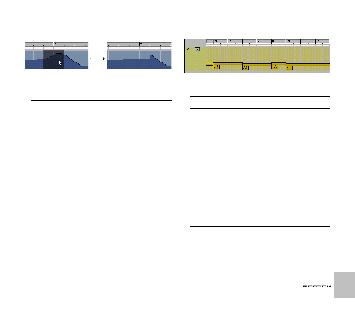
Background: How recorded controllers are handled
Even though the recording procedures are practically the same, the sequencer handles controllers differently from notes. While each recorded note
is a separate event, there are no “controller events” as such in the sequencer. Instead, it works like this:
Each sequencer track has a number of controller “subtracks” (one for each
automatable parameter in the corresponding device). A controller subtrack
can be viewed as a length of magnetic tape, which you can fill with controller
data.
When you haven’t yet recorded any automation for a parameter, its subtrack
is empty. The parameter is not automated.
As soon as you record anything for the controller, anywhere in the song, the
whole subtrack
This makes it possible to set up a static mix first, and then add some automated parameter changes anywhere in the song while maintaining the static
values elsewhere in the song.
is filled with controller data:
This is the section you recorded.
This is the original, static value for the parameter.
Recording Pattern Changes
If your song contains pattern devices, you probably want to use more than a
single pattern throughout the song. To facilitate this you can record pattern
changes in the sequencer (or draw them in manually, as described on page
25).
1. If you want to use the same pattern for the main part of the song
(and only want to add some variation patterns here and there), make
sure this “main pattern” is selected before you start recording.
When you first record a pattern change somewhere in the song, the originally selected pattern will be inserted throughout the rest of the song.
This is similar to the way controller automation works - see page 6.
2. Locate the sequencer track for the device, and make sure MIDI is
routed to the track.
That is, the MIDI connector symbol should be shown in the In column for
the track in the track list.
3. Start recording from the desired position.
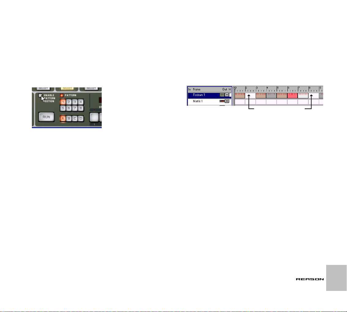
When playback starts, the pattern device will automatically start (provided the pattern section is enabled on the device).
4. During recording, change patterns with the Bank and Pattern buttons on the device panel.
Make sure to change the patterns slightly in advance - the actual pattern
change will be recorded (and happen) on the next downbeat according to
the main sequencer time signature.
5. When you are done, stop recording.
The green frame around the pattern buttons indicates that pattern changes are
automated for the device.
8
THE SEQUENCER
In the Arrange view, recorded pattern changes are indicated as dark yellow bars
(the pale yellow “strip” indicates that the track contains any pattern change data at
all).
Page 11

➜
Each pattern change will be recorded on a downbeat (at the start of
a new bar in the sequencer).
You can move pattern changes to other positions in the Edit View if
needed (see page 26).
➜
You can punch in on recorded pattern changes, to replace a section
of the track.
This works the same as punching in on controllers (see page 7).
➜
After recording the pattern changes, you can use the function Convert Pattern Track to Notes, to transfer the notes in the patterns to
the main sequencer.
This allows you to create unlimited variations by later editing the notes in
the Edit View. See below.
THE SEQUENCER
9
Page 12
Copying REX loops and Patterns to Sequencer Tracks
As described on page 136, you need to use the “To Track” function when using the Dr.Rex Loop Player device. This creates sequencer notes on the selected track, so that each slice in the REX loop gets a corresponding
sequencer note. Playing back the sequencer track will then play all slices in
the correct order, with the original timing of the loop.
Similar functions are available for the pattern devices (Redrum and Matrix).
• By using the function Copy Pattern to Track on the Edit menu or device context menu, you can copy the contents of the current pattern
to notes on the selected sequencer track.
• The function Convert Pattern Track to Notes works in a similar way,
but converts all patterns in a song to notes (taking pattern changes
into account).
The procedures differ slightly for the different device types:
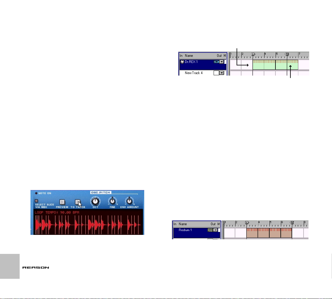
Using the “To Track” function for REX Loops
This assumes that you have loaded a REX loop into the Dr.Rex device. For
details, see page 135.
1. Set the left and right locator to encompass the section you want to
“fill” with notes for the REX loop.
2. Select the track connected to the Dr.Rex device.
To avoid confusion, make sure there are no events between the locators
on the track.
3. Click the “To Track” button on the Dr.Rex device panel.
Notes are created for the slices in the loop, and added to the track.
➜
If the length of the area between the locators is greater than the
length of the REX loop, the loop will be repeated on the track.
This function always creates an exact number of loops, meaning that the
last loop may “stick out” after the right locator.
The created notes are automatically grouped (as indicated
by the colored boxes). Read more about groups on page 16.
Here, the loop was 2 bars long. Since there are three bars between
the locators, the second loop will stick out after the right locator.
The “Copy Pattern to Track” function
This is available for the Redrum and the Matrix. It is useful when you have
created a single pattern and want to use it as starting point for editing in the
sequencer. You could also use this if you e.g. have created a drum pattern
and want to have this pattern play back some other type of device.
Proceed as follows:
1. Set the left and right locator to encompass the section you want to
“fill” with the notes in the pattern.
You may want to make sure the length of the area between the locators
is a multiple of the pattern length, to avoid “cutting off” the pattern.
2. Select the track connected to the pattern device.
In fact, you can select any track. For example, if the device is a Matrix, it
may make sense to copy the notes not to the Matrix track, but to the track
for the device
any sound in itself, and thus can’t be played by the sequencer notes).
3. Select the device and select “Copy Pattern to Track” from the Edit
menu or the device context menu.
➜
If you selected a track not connected to the pattern device, an alert
will appear, asking if that’s really what you want.
Click OK to proceed, or Cancel to abort.
The pattern is converted to sequencer notes on the track (see the notes below). If the length of the area between the locators is greater than the pattern
length, the pattern will be repeated to fill out the area.
controlled
by the Matrix (since the Matrix doesn’t produce
10
THE SEQUENCER
The created notes are automatically grouped (as indicated by the colored boxes). Read
more about groups on page 16.
Page 13
Redrum notes
When you use this function with the Redrum, you should note the following:
• The notes will have the pitch of the corresponding drum sound (see
“Using Redrum as a Sound Module” on page 96) and the velocity
depending on the Dynamic value.
Soft notes have velocity 30, medium notes have velocity 80 and hard
notes have velocity 127.
• You probably want to turn off the “Enable Pattern Section” switch
on the Redrum device panel.
Otherwise, the drum sounds will be “double-triggered” when you start
playback (once by the pattern section itself, once by the main sequencer).
Matrix notes
When you use this function for the Matrix, you should note the following:
• A note will be created for each pattern step with a gate value other
than zero.
The notes will have the pitch according to the key CV value for the step,
and the velocity according to the gate value.
• The curve CV is not copied.
• Make sure that the track is connected to the correct device!
Having the track connected to the Matrix itself is pointless, since the Matrix cannot produce any sound.
• You may want to disconnect or even remove the Matrix after performing a “Copy Pattern to Track”.
This is because you probably don’t want both the Matrix and the sequencer notes to play back at the same time.
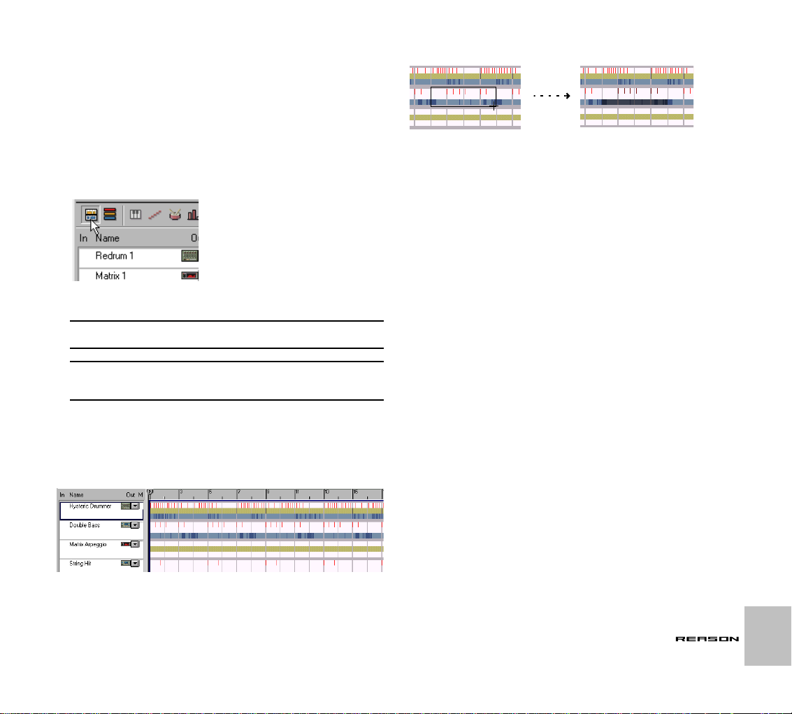
The “Convert Pattern Track to Notes” function
If you have recorded or drawn pattern changes on a Redrum or Matrix track,
you can have the whole track converted to notes, in the following way:
1. Select the track with the pattern changes.
2. Select “Convert Pattern Track to Notes” from the Edit menu or the
context menu for the track.
For each bar, the corresponding pattern is converted to notes on the
track (following the same rules as for the “Copy Pattern to Track” function). The track will play back just the same as when you played the pattern device with the pattern changes (including the Pattern Enabled/Mute
switch).
In these sections, the pattern
was muted (Pattern Enable off)
in the pattern track.
➜
All pattern changes are automatically removed from the track after
the operation.
Redrum notes
• The “Enable Pattern Section” switch is automatically turned off
when you use this function.
Matrix notes
• After performing “Convert Pattern Track to Notes”, you need to
move the contents to another track, or re-route the track to another
device.
Having the track connected to the Matrix itself is pointless, since the Matrix cannot produce any sound.
• You may want to disconnect or even remove the Matrix after performing this function.
This is because you probably don’t want both the Matrix and the sequencer notes to play back at the same time.
THE SEQUENCER
11
Page 14

Editing - About Snap
When you select and edit material (both in the Arrange View and the Edit
View), the Snap (Snap to Grid) function determines the result. By activating
Snap, editing becomes “restricted” to the note values selected on the Snap
pop-up menu (the Snap value). The Snap button and pop-up menu are located on the sequencer toolbar:
Use this pop-up menu to select the Snap value.
Click here to turn Snap on or off.
!
Note that you can select different Snap values for the Arrange View
and the Edit View.
Snap has an effect on the following operations:
➜
Moving the Song position, Locators and End marker.
When you adjust these markers with Snap activated, they will be “magnetic” to the Snap value.
➜
Selecting events by enclosing them in a selection rectangle.
Since the selection rectangle is magnetic to the snap value, this determines the smallest “block” you can select.
However, selecting by clicking directly on notes in the Edit View (or
Groups in the Arrange View - see page 17) is not restricted by Snap.
➜
Moving and duplicating events.
When you move one or several Events with Snap activated, they will
keep their relative distance to the Snap value positions. In the example
below, Snap is set to 1/4 (quarter notes):
➜
Drawing Groups in the Arrange View.
When you create Groups with the Pencil tool, their start and end positions will be magnetic to the snap value positions. See page 16.
➜
Drawing events in the Edit view.
The Snap value determines the smallest note position on which you can
draw a note or insert a controller value or pattern change. Furthermore,
the Snap value determines the smallest length of the events when you
draw. See page 20.
12
THE SEQUENCER
Page 15
Editing in the Arrange View
The Arrange View allows you to view several tracks at the same time, and
provides a good overview of the song. This view is best suited for large-scale
editing, such as rearranging blocks of music, adding or removing bars or applying quantizing and editing functions to events on different tracks at the
same time.
➜
To select the Arrange View, click the Arrange View button in the top
left corner of the sequencer area.
You can also toggle between Arrange View and Edit View by pressing
[Shift]-[Tab] or [Command]/[Ctrl]-[E].
!
On the following pages we will use the word “event” as a collective
name for notes, controller changes and pattern changes.
The procedures below apply to separate events in the Arrange
!
View. Some techniques are different for Grouped events, as described on page 16.
Selecting Events
Each track in the Arrange View is divided vertically into three “lanes”, in
which events are shown as thin vertical lines. The top lane shows notes (including drum notes and REX slices) in red, the middle lane shows pattern
changes in yellow and the lower lane shows controller value changes in blue.
To select events in the Arrange view, click and drag a selection rectangle.
➜
If Snap is activated, the selection rectangle will be magnetic to the
Snap value.
➜
You can drag a selection rectangle covering only one lane, thereby
selecting only the notes, pattern changes or controllers.
You can also draw a selection rectangle covering several tracks.
➜
If you hold down [Shift] when you select events, any already selected events remain selected.
This allows you to make multiple, non-contiguous selections: first select
some events, then press [Shift] and select some more events, and so on.
➜
You can also use the “Select All” function on the Edit menu.
This selects all events, controllers and pattern changes in the song.
➜
The selection you make in the Arrange View will be maintained if
you select the Edit View.
See page 21.
➜
To de-select events, just click anywhere in an empty area.
Moving Events
To move the selected events, click in the selection, and drag and drop it on a
new position.
➜
When you move the selection, it is “magnetic” to the lanes.
That is, you cannot drag notes to a controller lane, etc.
➜
If you hold down [Shift] and drag, movement is restricted to horizontal or vertical only.
➜
If Snap is activated, you will only be able to drop the selection so
that it maintains its relative distance to the Snap value positions.
See page 12.
THE SEQUENCER
13
Page 16
Duplicating Events
To duplicate the selected events, hold down [Option] (Mac) or [Ctrl] (Windows) and proceed as when moving events.
➜
You can also use the Duplicate Track function on the Edit menu or
the track context menu.
This creates a copy of the selected track, complete with all events. The
duplicated track will appear below the original track in the track list.
Using Cut, Copy and Paste
You can move or duplicate events using the Cut, Copy and Paste commands
on the Edit menu. When you Paste, the events appear at the song position,
on their original track(s).
!
If you have deleted the original tracks, or if you Paste into another
Reason song document, new tracks will be created as needed.
➜
See the note below about Copying and Pasting whole tracks!
Using Copy and Paste to repeat a section
When you Cut or Copy a selection, the song position will automatically move
to the end of the selection (or, if Snap is activated, to the closest Snap value
position after the end of the selection). This allows you to quickly repeat a
section, in the following way:
1. Make sure playback is stopped.
2. Set the Snap value to “Bar” (or to the length of the section you want
to repeat, if is smaller than one bar).
3. Activate Snap.
4. Select the section you want to repeat.
Since you can make selections over several tracks, this is a quick way to
copy entire song sections.
!
Note that Snap doesn’t apply in quite the same way when selecting
Groups (see page 17). Make sure the selection contains exactly
what you want before proceeding.
5. Select Copy from the Edit menu.
The song position is moved to the closest snap value after the end of the
selection (provided that playback is stopped).
6. Select Paste from the Edit menu.
The copied section is pasted in, and the song position is moved to the
end of pasted section.
7. Paste again, as many times as you want to repeat the section.
Using Cut, Copy and Paste with Tracks
You can select one or several tracks by clicking or [Shift]-clicking in the track
list. This allows you to use Cut or Copy on the track, complete with contents.
➜
If you Paste the track(s) into their original song, this simply duplicates the tracks.
However, the Pasted tracks will not be connected to any devices in the
rack.
➜
You can also Paste the track(s) into another song.
Note that only the tracks (complete with contents) are copied and pasted
- not their respective devices. You may want to separately copy and
paste the devices to the other song.
Deleting Events
To delete events in the Arrange view, select them and press [Delete], [Backspace] or select Delete from the Edit menu.
14
THE SEQUENCER
Page 17

Inserting and Removing Bars
When editing the overall structure of a song, you may need to rearrange the
order and length of whole sections (e.g. make the “verse” two bars shorter,
add a few bars to the intro, etc.). On the Edit menu or sequencer context
menu you will find two useful functions for this:
Insert Bars Between Locators
This function inserts an empty area between the locators. All events after the
left locator are moved to the right to “make room” for the inserted area.
Remove Bars Between Locators
This function removes all material between the locators. All events after the
right locator are moved to the left to “fill out” the gap after the removed section.
✪
The “Remove Bars Between Locators” function will automatically
shorten any Groups intersected by the locators. This can be used
as a feature in itself, as described on page 18.
Other Editing Functions in the Arrange View
You can also apply quantizing (see page 28) and use the Change Events
function (see page 29) in the Arrange View. This is useful since it allows you
to edit events on several tracks in one go.
➜
Note that you can select one or several tracks and have quantizing
or Change Events apply to all events on the selected tracks.
Selecting several tracks is done by [Shift]-clicking in the track list.
THE SEQUENCER
15
Page 18
Using Groups
Sometimes it is practical to work with a section of events as one entity. This
is done by Grouping the events. You may for example have a two-bar bass
line that you want to move or repeat in the song - by Grouping the events,
you can select, move and handle the bassline as a single object.
!
This applies to the Arrange View only - you can still edit individual
events in a Group in the Edit View.
Appearance and Color
In the Arrange View, Groups appear as colored boxes.
Creating Groups
There are two main ways to create Groups:
By using the Group command
1. Select the events that you want to Group.
It doesn’t matter which lanes you select - all notes, pattern changes and
controllers within the area will be included in the Group.
➜ If you select events on several tracks, one Group for each track will
be created.
Each Group can only contain events on one track.
2. If you want the Group to have a specific length, activate Snap and
select an appropriate Snap value.
Often it is practical to create Groups that are one or several whole bars
long.
3. Select Group from the Edit menu or the sequencer context menu.
Or, hold down [Command] (Mac) or [Ctrl] (Windows) and press [G].
16
The color of the Groups depends on their contents:
!
Groups with the same color contain the same events.
This makes it easy to get an overview of the song, since variations will appear as Groups in another color.
These Groups are “variations”
- all the others have the same contents.
THE SEQUENCER
The events are Grouped.
By drawing with the Pencil tool
1. Select the Pencil tool.
You can also select the Pencil tool momentarily by holding down [Command] (Mac) or [Alt] (Windows).
2. If you want the Group to have a specific length, activate Snap and
select an appropriate Snap value.
Often it is practical to create Groups that are one or several whole bars of
length.
3. Click where you want the Group to start, drag to the right and release the mouse button.
A Group is created, containing the enclosed Events. It is also possible to
create empty Groups this way.
✪ Groups are also automatically created when you use the “To
Track”, “Copy Pattern to Track” and “Convert Pattern Track to
Notes” functions. See page 10.
Page 19

Selecting Groups
To select a Group, just click on it in the Arrange View.
This Group is selected.
➜ If you hold down [Shift] and click, you can select multiple Groups.
You can de-select individual Groups by [Shift]-clicking them again.
➜ You can also select Groups by clicking and dragging a selection
rectangle, just as with events.
If Snap is on, the selection rectangle will be magnetic to the Snap value
positions. However, note that a Group doesn’t have to be fully enclosed
by the rectangle to be selected - the selection rectangle only needs to intersect or touch the Group.
✪ Note that it’s possible to select Groups and “loose events” at the
same time with this method. Make sure the selection rectangle encloses the elements you want!
➜ Another way of selecting Groups is to use the arrow keys on the
computer keyboard.
Pressing the right arrow key selects the next Group on the track, pressing
the down arrow key selects the closest Group on the track below, etc.
Holding down [Shift] and using the arrow keys allows you to make multiple selections.
➜ If you select a Group and go to the Edit View, all events in the Group
will be selected.
➜ To de-select the selected Group(s), click anywhere in an empty part
of the Arrange View.
Resizing Groups
When a Group is selected, a handle appears on its right edge. You can click
on this handle and drag to make the Group smaller or larger. The following
rules apply:
➜ If you drag to the left to make the Group smaller, any events that
end up outside the Group boundary are no longer included in the
Group.
As a consequence, if you drag the handle all the way past the start of the
Group, all events are Ungrouped (see below).
➜ If you drag to the right to make the Group larger, any events you en-
close will become part of the Group.
➜ Note: Groups cannot overlap!
This means that if you enlarge a Group so that it partially covers another
Group, this will automatically resize the other Group as well:
The second Group now starts here!
THE SEQUENCER
17
Page 20

Dividing Groups
You can divide a Group into two by clicking with the Pencil tool at the desired
position and dragging to the end of the Group.
Find Identical Groups
This command on the Edit menu helps you locate all Groups with the same
contents:
1. Select a Group.
2. Select “Find Identical Groups” from the Edit menu.
All Groups with the same contents are selected in the Arrange View.
Actually, this is just a consequence of the fact that Groups cannot overlap.
As soon as you create a Group that overlaps another Group, the other Group
is automatically resized. For example, if you were to draw a small Group
within a larger Group, you would end up with three Groups:
Tip: Splitting Groups on several Tracks
If you have Groups on several tracks and want to split these at the same position, you can use the following method:
1. Set both the Left and the Right Locator to the desired split position.
2. Select “Insert Bars Between Locators” from the Edit menu.
The Groups are split.
Combining Groups
There are two main ways to combine two or more Groups into one:
By using the Group command
1. Select the first and the last Group that you want to combine.
All Groups in between these will be included as well.
2. Select Group from the Edit menu.
You will now have one larger Group.
By Resizing
1. Click the size handle of the first Group and drag to the right.
2. Release the mouse button at the end of the last Group.
All Groups in between are combined to one larger Group.
Ungrouping
There are two ways to dissolve a Group:
➜ Select it and select Ungroup from the Edit menu or sequencer con-
text menu,
or
➜ Click on the Group size handle and drag it all the way to the left.
Neither of these methods affect the events in the Group, they just remove the
Grouping.
Editing with Groups
You can work with Groups much like you edit selected events in the Arrange
view:
➜ To move a Group, click on it and drag it to a new position, taking the
Snap value into account.
If you move the Group so that it partially overlaps another Group, the
other Group will automatically be resized. If the moved Group overlaps
the other Group completely, you will get one large Group containing the
events from both.
➜ To duplicate a Group, hold down [Option] (Mac) or [Ctrl] (Windows)
and proceed as when moving.
This duplicates the Group and all its contents. You can also use Copy
and Paste for this, following the same rules as for selected events.
➜ To delete a Group, select it and press [Delete], [Backspace] or se-
lect Delete from the Edit menu.
This deletes the Group and all its contents.
18
THE SEQUENCER
Page 21

The Edit View
The Edit View allows you to perform detailed editing to the events on a single
track. This is also where you create notes, pattern changes and controller
values from scratch by drawing.
➜ To select the Edit View, click the Edit View button in the top left cor-
ner of the sequencer area.
About the Lanes
The Edit View is (or can be) divided vertically into lanes. There are six different lanes, suitable for editing different types of events. Any combination of
lanes can be shown. You show and hide lanes by clicking their respective
buttons in the sequencer toolbar:
Key lane Drum lane
Pattern lane
Controller lane
You can also toggle between Arrange View and Edit View by pressing
[Shift]-[Tab] or [Command]/[Ctrl]-[E].
Selecting a Track for Editing
The Edit View shows the events of the track that has the focus in the track
list.
➜ If one track is selected when you enter Edit View, that track will have
the focus and its events will be shown.
➜ If more than one track is selected in the track list when you select
Edit View, the track you last clicked on will have focus.
➜ You can change edit track at any time, by clicking in the track list.
This way you can stay in the Edit View and select different tracks for editing, without having to go back to the Arrange View.
REX lane
➜ If you hold down [Option] (Mac) or [Alt] (Windows) and click a Lane
button, only that lane will be shown (all other lanes are hidden).
By default, the lanes that are shown when you select Edit View depends on
the device type to which the track is connected (and whether the track contains controller data). For Redrum tracks, the Drum lane, Velocity lane and
Pattern lane are shown, for Dr.Rex tracks, the REX lane and Velocity lane
are shown, and so on.
However, once you show or hide lanes, the new combination of lanes will be
stored individually for each track. The next time you select Edit View for that
track, the lane configuration will be the same.
Velocity lane
Resizing and Zooming
➜ You can resize lanes by dragging the dividers between them.
➜ Where applicable, the lanes have individual zoom controls and
scrollbars.
THE SEQUENCER
19
Page 22

➜ For extensive editing, you may want to maximize the sequencer
area so that it fills the window.
This is done by clicking the Maximize Sequencer button or by holding
down [Command] (Mac) or [Ctrl] (Windows) and pressing [2] on the left
part of the computer keyboard.
The Maximize Sequencer button.
About the Ruler and the Group strip
At the top of the Edit View you will find the ruler. Just like the ruler in the Arrange View, this shows meter positions (bars and beats), helping you find the
right positions in the song.
➜ You can adjust the horizontal zoom individually for the Edit View
and the Arrange View.
This makes sense, as you will probably work with a larger magnification
when performing fine editing.
Just below the ruler is a narrow empty strip. This shows the Groups (if any)
as colored bars, providing additional means of orientation in the Edit view.
Groups
Drawing and Editing Notes
Notes are drawn and edited in one of three lanes: the Key lane, the Drum
lane and the REX lane:
The Key lane. The piano keyboard to the left indicates the pitch of the notes, covering
the whole MIDI note range (C-2 to G8). Note that the black and white keys are reflected
in the background colors of the grid, making it easier to find the right pitch when drawing
and moving notes!
This is the lane to use when editing Subtractor or Sampler tracks.
The Drum lane. This is divided vertically into ten pitches, corresponding to the ten drum
sound channels on a Redrum device (and named accordingly, if the track is connected
to a Redrum device). Use this for editing drum tracks.
20
✪ When you edit events within a Group, you will note that the Group
indicator changes color. This is because the color of a Group depends on its contents, as described on page 16.
THE SEQUENCER
The REX lane. This is divided vertically into pitches (from C3 and up), corresponding to
the slices in a Dr.Rex loop player device. Use this for editing Dr.Rex tracks.
➜ In all three lanes, the actual notes are shown as “boxes”, with the
note length indicated by the width of the box and the velocity values
indicated by the color of the box (the darker the color, the higher the
velocity).
The basic note editing procedures are the same for all three lanes.
Page 23

Drawing notes
1. If you want to restrict note input to certain note values (e.g. sixteenth notes), set the Snap value accordingly and activate Snap.
2. Select the Pencil tool.
You can toggle temporarily between the Arrow tool and the Pencil tool by
holding down [Command] (Mac) or [Alt] (Windows).
3. If needed, click in the piano keyboard display, drum sound list or
slice list to find the correct pitch.
If the track is connected to a device, this will play the corresponding note.
4. Click in the note display part of the lane, at the desired position.
A note will be inserted at the closest Snap value position.
➜ If you just click, the note will get the length of the Snap value.
This is true regardless of whether Snap is activated or not.
➜ If you instead click and keep the mouse button pressed, you can
drag to the right to set the length of the note.
If Snap is on, the length will be a multiple of the Snap value (unless you
hold down [Shift] while you drag). Also, see the note about drum note
lengths below.
Selecting notes
To select notes in the Edit View, use one of the following methods:
➜ Click on a note with the Arrow tool to select it.
➜ To select several notes, hold down [Shift] and click.
You can de-select individual notes by [Shift]-clicking them again.
➜ You can also click and drag a selection rectangle around the notes
you want to select.
If Snap is on, the selection rectangle will be magnetic to the nearest snap
value positions. For example, if Snap is set to “Bar”, dragging a rectangle
will select all notes within an exact range of bars (and within the pitches
enclosed by the rectangle).
➜ You can select the next or previous note on the track by pressing
the right or left arrow key on the computer keyboard.
Holding down [Shift] and using the arrow keys allows you to make multiple selections.
➜ To select all notes on the track, use the Select All function on the
Edit menu.
Make sure that the correct lane (Key, Drum or REX) has focus first - otherwise you may select all controllers or pattern changes. To set focus to
a lane, click somewhere in it (focus is indicated by a thin extra border
within the lane).
➜ To deselect all notes, click somewhere in an empty area.
Moving notes
➜ To move a note, click and drag it to a new position.
If several notes are selected, all will be moved. The individual distance
between the moved notes will be kept.
➜ If Snap is on, the moved events will keep their relative distance to
the Snap value positions.
For example, if Snap is set to “Bar”, you can move the selected notes to
another bar without affecting their timing.
➜ If you hold down [Shift] when you drag, movement is restricted to
horizontal or vertical only.
This helps you move notes without accidentally transposing them, or
transposing notes without accidentally changing their meter position.
Duplicating notes
To duplicate the selected notes, hold down [Option] (Mac) or [Ctrl] (Windows) and proceed as when moving notes.
Using Cut, Copy and Paste
You can move or duplicate events using the Cut, Copy and Paste commands
on the Edit menu.
➜ When you Cut or Copy, the song position is automatically moved to
the end of the selection (or, if Snap is activated, to the closest Snap
value position after the end of the selection).
You can use this for repeating events, as described on page 14.
➜ When you Paste, the events appear at the song position, on their
original track(s).
THE SEQUENCER
21
Page 24

Resizing notes
When you select a note, a handle appears on its right edge. You can click on
this handle and drag to make the note shorter or longer.
➜ If Snap is on, the end of the note will be magnetic to the Snap value
positions.
You can disable this function temporarily by pressing [Shift] when you
drag. This allows you to resize the note to any length, regardless of the
Snap value.
➜ If several notes are selected, all will be resized by the same amount.
About resizing drum notes
Drum notes can be resized as any other notes. However, the result of this
depends on the settings of the Decay/Gate switch and the Length knob for
the drum sound on the Redrum panel:
➜ If Decay mode is selected, the drum sound will play to its end, re-
gardless of the note length.
Or rather, it will fade out according to the Length setting.
➜ If Gate mode is selected, the note length affects the resulting
sound.
However, the maximum length of the sound is set by the Length knob the sound will be cut off after this length, regardless of the note length.
Finally, even if the Length knob is set to its maximum value, the sound
will not play longer than the length of the drum sample.
Deleting notes
To delete notes, select them and press [Backspace] or [Delete], or select Delete from the Edit menu.
Editing velocity
The velocity values of notes are edited in the Velocity lane.
The velocity values are shown as bars, with higher bars indicating higher velocity. Note
also that the color of the notes and bars reflect the velocity.
To change the velocity of a note, click on its velocity bar with the Pencil tool
and drag the bar up or down. You can also edit the velocity of several notes
by dragging the pencil across the bars, at the desired height.
Drawing a velocity ramp.
However, note the following feature:
! If you hold down [Shift] when you edit velocity values with the Pen-
cil tool, only the selected notes will be affected!
This can be very useful, especially in “crowded” sections with lots of notes.
Consider for example if you have a busy drum beat, and want to adjust the
velocity of the hi-hat notes only. Simply dragging with the pencil tool would
change the velocity of all other drum notes in the area, but if you first select
the hi-hat notes in the Drum lane and press [Shift], you can edit their velocity
without affecting any other notes!
22
THE SEQUENCER
Page 25

Editing Controllers
Controllers are shown and edited in the Controller lane. This lane in turn is divided into several “subtracks”, one for each automatable parameter for the
corresponding device.
The Controller lane for a Subtractor track, with three controllers shown.
Showing and Hiding Controllers
For each track, you can select which controllers should be shown. This can
be done in several ways:
➜ Hold down [Option] (Mac) or [Alt] (Windows) and click on a parame-
ter on a device panel in the rack.
This sets focus to the first sequencer track connected to the device,
opens Edit View, brings the Controller lane and shows the automation
subtrack for the specified parameter, all in one go.
➜ You can do the same thing by selecting “Edit Automation” on the
context menu for the parameter.
You bring up the parameter context menu by [Ctrl]-clicking (Mac) or rightclicking (Windows) on the parameter on the device panel.
➜ By using the Controller pop-up menu on the sequencer toolbar, you
can hide or show individual controllers from the sequencer.
Shown controllers are indicated by a tick mark on the pop-up menu - select a controller to show it or hide it.
Controllers for which there is data (automation) in the track are indicated
with an asterisk next to the controller name.
➜ Click the “Show All Device Controllers” button to show all control-
lers available for the track’s device.
➜ Click the “Show All Automated Controllers” button to show all con-
trollers for which you have recorded or drawn automation in the
Track.
➜ Click the “Hide All Controllers” to hide all controllers.
This will leave the Controller lane empty.
✪ If you use a Mac with a two-button mouse, it’s a good idea to assign
[Ctrl]-click to the right mouse button, allowing you to bring up context menus by right clicking.
THE SEQUENCER
23
Page 26

Drawing and Editing Controllers
Regardless of whether you’re editing recorded controllers or creating controller changes from scratch, you do it by drawing with the Pencil tool.
Note:
➜ If Snap is on, the controller value change you enter will snap to the
nearest Snap value position.
Also, the length of the changed section will be a multiple of the Snap value.
In this example, Snap is set to 1/4. Thus, the controller changes you enter will be in
“steps”, one or more quarter notes in length.
➜ If the controller hasn’t been automated yet (the words “Not Auto-
mated” are shown in the Controller lane), it is a good idea to first set
the parameter to a good “default value” on the device panel.
The reason is that as soon as you enter a controller value, the rest of the
track will be filled with the original value of the parameter (the value set
on the device panel). This works exactly the same as when recording
controllers - see page 6.
Selecting sections of a controller track
To select a section of the “subtrack” for a controller, click and drag a selection rectangle with the Arrow tool. If Snap is on, the selection will be magnetic
to the Snap value positions, just as when selecting notes.
The selected section is shown as a shaded rectangle.
➜ By holding down [Shift] and dragging, you can select multiple, dis-
continuous sections of the controller subtrack.
✪ If you select Groups or sections of the controller lane in the Arrange
View, this section will be selected when you got to Edit View and
vice versa.
Moving and Duplicating Controller sections
➜ To move a selected controller section, click and drag it to another
position on the same subtrack.
Snap is taken into account as usual.
➜ To duplicate a selected controller section, hold down [Option] (Mac)
or [Ctrl] (Windows), click and drag it.
! Moving or duplicating controllers will replace the controller values
at the new position (just as if you had edited them with the Pencil
tool).
Using Cut, Copy and Paste
You can move or duplicate selected controller sections using the Cut, Copy
and Paste commands on the Edit menu.
➜ When you Cut or Copy, the song position is automatically moved to
the end of the selection (or, if Snap is activated, to the closest Snap
value position after the end of the selection).
You can use this for repeating events, as described on page 14.
➜ When you Paste, the controller section appears at the song posi-
tion, on its original subtrack.
24
THE SEQUENCER
Page 27
Deleting Controller sections
You can delete the selected controller section by pressing [Backspace] or
[Delete] or by selecting Delete from the Edit menu. The result is this:
The controller value just before the deleted selection will remain until the end of the
selection.
! You can´t remove all automation using this method - there will al-
ways be at least one controller value left. To remove all automation,
use the Clear Automation function:
Clearing Automation
To remove all automation for a controller, select “Clear Automation” from one
of the following menus:
➜ The context menu for the controller subtrack.
This appears when you [Ctrl]-click (Mac) or right-click (WIndows) in the
subtrack.
➜ The Edit menu.
Requires that the controller subtrack has focus. Click in the subtrack if
you are uncertain.
➜ The parameter context menu.
This appears when you [Ctrl]-click (Mac) or right-click (WIndows) on the
parameter on the device panel.
Note that this clears all automation for the parameter, on all tracks!
Selecting “Clear Automation” will remove all controller values from the subtrack, and the text “Not Automated” will be shown.
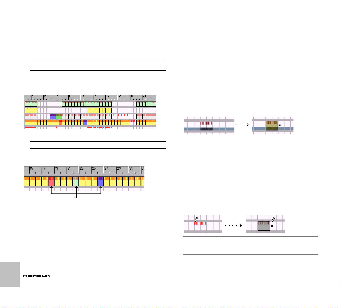
Inserting and Editing Pattern Changes
Pattern changes are viewed and edited in the Pattern lane:
A pattern change is shown as a yellow “tab” with the Bank and Pattern number. From the tab, a bar stretches to the right, for as long as the selected pattern is “active”, i.e. to the next pattern change.
! When you record pattern changes, they are automatically posi-
tioned on downbeats (at the beginning of new bars).
Inserting Pattern Changes
To insert a Pattern change, proceed as follows:
1. If you haven’t automated any pattern changes for the track yet (the
words “Not Automated” are shown in the Pattern lane), it is a good
idea to first select a “default pattern” in the pattern device.
This is especially useful if you are using a main pattern and want to insert
changes to variation pattern here and there.
The reason is that just like when you record pattern changes, the rest of
the track will be “filled” with the original value as soon as you enter a pattern change somewhere on the track.
2. Activate Snap and set the Snap value to the note position where you
want to insert pattern changes.
It is probably a good idea to set Snap to “Bar”, at least if you are working
with patterns of a length corresponding to the time signature (e.g. 16 or
32 step patterns and 4/4 time signature). However, if you are working
with patterns of another length, it can make sense to use other Snap values.
! Don’t insert pattern changes with Snap turned off, unless you want
chaotic rhythm changes!
THE SEQUENCER
25
Page 28
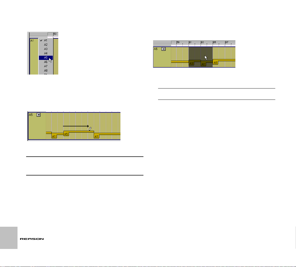
3. Pull down the Pattern pop-up menu to the left in the Pattern lane,
and select the pattern you want to insert.
The selected pattern is shown next to the pop-up menu.
The patterns are listed with the bank letter and pattern number (A1, A2, A3, and so
on).
4. Click with the Pencil tool at the position where you want the pattern
change to happen, and keep the mouse button pressed.
5. Drag to the right.
When you drag, you will see the previous or original pattern being replaced by the pattern you insert.
6. Release the mouse button at the position where you want the pattern change to “end”.
! The “Pattern Enable/Mute” switch (the button above the pattern se-
lection buttons on the device panel, used for temporarily silencing
the pattern playback) is automated using controller automation. The
controller is called “Pattern Enabled”.
Selecting Pattern Changes
To select a section of Pattern lane, click and drag a selection rectangle with
the Arrow tool. If Snap is on, the selection will be magnetic to the Snap value
positions, just as when selecting notes.
The selected section is shown as a shaded rectangle.
➜ By holding down [Shift] and dragging, you can select multiple, dis-
continuous sections of the Pattern lane.
✪ If you select Groups or sections of the pattern lane in the Arrange
View, this section will be selected when you got to Edit View.
Moving and Duplicating Pattern Change sections
You can move and duplicate selected sections of the Pattern lane, just as
when moving controller sections. Just like when inserting pattern changes, it
is recommended that Snap is activated (and in most cases set to “Bar”) when
you do this.
You can also move or duplicate sections using the Cut, Copy and Paste
commands on the Edit menu. Again, the same rules apply as when editing
controllers.
26
THE SEQUENCER
Page 29

Deleting Pattern Change sections
You can delete the selected section of the Pattern Lane by pressing [Backspace] or [Delete] or by selecting Delete from the Edit menu. The result is
this:
The pattern before the deleted section will remain selected until the end of the section.
! Again, make sure Snap is activated.
! You can´t remove all pattern change data using this method. To re-
move all pattern automation, use the Clear Automation function:
Clearing Automation
To remove all pattern changes, proceed as follows:
1. [Ctrl]-click (Mac) or right-click (WIndows) in the Pattern lane.
The context menu appears.
2. Select “Clear Automation”.
This will remove all pattern changes from the track, and the text “Not Automated” will be shown.
THE SEQUENCER
27
Page 30

Quantizing
The Quantize function moves recorded notes to (or closer to) exact note
value positions. This can be used for correcting errors, “tightening up” recorded music or changing the rhythmic feel.
Applying Quantizing
In Reason, you use the Quantize function in the following way:
1. Select the notes you want to quantize.
Only notes will be affected, so you can select Groups or complete Tracks
if you like.
2. Pull down the Quantize pop-up menu on the sequencer toolbar and
select a Quantize value.
This determines to which note values the notes will be moved when you
quantize. For example, if you select sixteenth notes, all notes will be
moved to (or closer to) the closest sixteenth note position.
The Quantize pop-up menu.
3. Select a value from the Quantize Strength pop-up menu.
This is a percentage, governing how much each note should be moved. If
you select 100%, notes will be moved all the way to the closest Quantize
value positions; if you select 50%, notes will be moved half-way, etc.
4. Click the Quantize button or select “Quantize Notes” from the Edit
menu.
The selected notes are quantized.
The Quantize
button
In this example, a sloppily recorded hi-hat pattern is quantized to straight sixteenth
notes (Quantize value 1/16, Strength 100%).
Quantizing to Shuffle
On the Quantize pop-up menu, you will also find an option called “Shuffle”. If
this is selected when you quantize, the notes are moved towards sixteenth
note positions, but with the Shuffle applied.
As described in the Getting Started book, Shuffle creates a “swing feel” by
delaying the even-numbered sixteenth notes (the sixteenth notes that fall in
between the eighth notes). The amount of Shuffle is set with the Pattern
Shuffle control on the transport panel.
The Pattern Shuffle control.
Quantizing to Shuffle is useful if you want to match the timing of recorded
notes with pattern devices in the song (if Shuffle is activated in the patterns).
➜ The Quantize Strength setting applies as when quantizing to regular
Quantize values.
28
THE SEQUENCER
Page 31

Quantizing to Grooves
The Quantize pop-up menu also contains three items named “Groove 1-3”.
These are three different, slightly irregular rhythmic patterns. If you select
one of these as Quantize value and apply Quantize, your notes will be
moved towards the note positions in the Groove pattern, creating different
rhythmic feels.
Creating your own Groove
You can create your own groove and apply this using Groove Quantize:
1. Create or record a rhythmic note “pattern” of some kind.
You may for example record a drum pattern, or use the notes playing the
slices in a REX loop.
2. Select the notes you want to include in the user groove.
The groove can be of any length, but it’s usually most practical to make it
one or two bars long.
3. Select “Get User Groove” from the Edit menu or sequencer context
menu.
Your pattern is stored as the User groove.
4. Select any notes that you want to quantize, make sure “User” is selected as Quantize value, and quantize as usual.
The rhythmic feel of your groove is applied to the notes.
! The User Groove is only stored temporarily - it isn’t included when
you save your Song.
Quantizing during recording
You can have Reason quantize notes automatically when they are recorded.
This is done by activating the “Quantize Notes during Recording” button on
the sequencer toolbar, before you start recording.
The Change Events Dialog
The Change Events dialog contains some special editing functions. Proceed
as follows:
1. Select the events to which you want to apply the editing functions
(in the Arrange view or Edit view).
The Change Events functions are mainly used with notes, but the Scale
Tempo function will also affect controllers and pattern changes (see below).
2. Select Change Events from the Edit menu or the context menu for
the selected events.
The Change Events dialog appears.
The Quantize value and Strength settings apply as usual.
3. Make settings for one of the functions in the dialog and click the Apply button next to the settings.
All settings can be made by clicking the spin controls or by clicking in a
value field and entering a value numerically. The functions are described
below.
4. If you like, use other settings in the same way.
You can use the transport controls as usual while the dialog is open. This
allows you to play back the events to check out the changes.
5. When you are done, close the dialog.
THE SEQUENCER
29
Page 32

Transpose
This function transposes the selected notes up or down, by the specified
number of semitones.
Velocity
Adjusts the velocity of the selected notes.
➜ The Add field lets you add a fixed amount to the velocity values.
To subtract, enter a negative amount. Note that the possible velocity
range is 1-127. Adding an amount to a note with velocity 127 will not
make any difference.
➜ The Scale field allows you to scale velocities by a percentage factor.
Scaling with a factor above 100% will increase the velocity values, but
also make the difference between soft and hard notes bigger.
Scaling with a factor below 100% will decrease the velocity values, but
also make the difference between soft and hard notes smaller.
➜ By combining the Add and Scale functions, you can adjust the “dy-
namics” of the notes in various ways.
For example, by using a Scale factor below 100% and Add a suitable
amount, you can “compress” the velocity values (decreasing the difference between the velocity values without lowering the average velocity).
Scale Tempo
This function will make the selected events play back faster (Scale factor
above 100%) or slower (Scale factor below 100%). This is achieved by
changing the position of the events (starting from the first selected event)
and adjusting the length of the notes accordingly.
Alter Notes
This function alters the properties pitch, length and velocity of the selected
notes, in a random fashion.
➜ The function will only “use” values that already exist among the se-
lected notes.
For example, if you have selected notes within a specific pitch interval,
the altered notes will remain within this pitch interval. Similarly, only velocity values and note lengths that were already used in the selection will
be applied by the Alter function. You could say that the function “shuffles”
the existing properties in a selection and redistributes them among the
notes.
! This means that the less variation there is among the selected
notes, the less the effect of the Alter function.
➜ You can adjust the amount of Alteration with the Amount value.
✪ This function is especially useful for experimenting with REX loops.
Select some notes on a Dr.Rex track and use Alter Notes to create
instant variations, without losing the timing and rhythmic feel of the
loop!
30
The result of applying Scale Tempo with the Scale factor 200% (double speed).
➜ The buttons [*2] and [/2] are “shortcuts” to Scale factors 200% and
50%, respectively.
These are probably the most common values used, simulating double
tempo and half tempo.
! This function affects all types of events: notes, controllers and pat-
tern changes!
THE SEQUENCER
Page 33

Importing and Exporting MIDI Files
Reason can import and export standard midi files (SMF). This allows you to
transfer MIDI data between Reason and other applications.
Importing a MIDI File
To import a Standard MIDI File, select “Import MIDI File” from the File menu
In the file dialog that appears, locate and open the MIDI file.
➜ Under Windows, MIDI files have the extension “.mid”.
On a Macintosh, MIDI files are recognized if they have the file type “Midi”.
Now, a number of new tracks are created in Reason’s sequencer. The tracks
will have their original name, with their original MIDI channel added.
➜ If the imported MIDI file is of “Type 1”, there will be one sequencer
track for each track in the MIDI file.
➜ If the imported MIDI file is of “Type 0” (that is, it contains one track
with MIDI events on multiple channels), there will be one sequencer
track for each used MIDI channel.
➜ Any tempo changes in the MIDI file are disregarded.
The tempo in Reason will be set to the first tempo in the MIDI file.
➜ The new tracks will not be connected to devices in the rack.
You will need to connect the tracks manually to the proper devices, by
using the Out pop-up menu in the track list.
➜ All controller data in the MIDI file is included.
This means that pitch bend, volume and modulation wheel data are preserved properly. However, some controllers may “mean” different things
for the original MIDI instruments used when creating the MIDI file and the
devices in Reason. When you have connected a sequencer track to a device, you may therefore need to remove some unwanted automation
from the track.
Green frames will appear for the automated parameters in the device panels. This
helps you locate any unwanted controller data.
Exporting a MIDI File
To export your Reason song as a MIDI file, proceed as follows:
1. Set the End (E) marker at where you want the MIDI file to end.
The MIDI file will contain all events on all tracks from the start of the song
to the End marker.
2. Select “Export MIDI File” from the File menu.
3. In the file dialog that appears, specify a name and location for the
file.
Under Windows, the file will automatically get the extension “.mid”. Under
MacOS, this is not required. However, if you want the MIDI file to be recognizable under Windows (and by some hardware sequencers), you may
want to activate the option “Add Extension to File Name” before saving.
4. Click Save.
MIDI files exported by Reason will have the following properties:
➜ The MIDI file will be of Type 1, with one MIDI track for each track in
the Reason sequencer.
The tracks will have the same names as in the Reason sequencer.
➜ Since the Reason sequencer doesn’t use MIDI channels as such, all
tracks will be set to MIDI channel 1.
➜ The sequencer tempo is included in the MIDI file.
THE SEQUENCER
31
Page 34

32
THE SEQUENCER
Page 35

ROUTING AUDIO AND CV
2
Page 36

About the various signals that can be routed
This chapter describes the various ways you can route signals in Reason.
The following signal types are used:
Audio
Apart from the Matrix Pattern Sequencer, all devices have audio connectors
on the back. The audio connectors carries audio signals to or from devices
via virtual “cables”.
➜ Audio connectors are shown as large “quarter inch” jacks.
➜ Audio Effects devices, which are used to process audio, have both
audio inputs and outputs.
➜ Instrument devices, which generate audio, have either mono or ste-
reo left/right audio output connectors.
You do not have to use both outputs for devices with stereo outputs. Use
the left output to get a mono signal from a stereo device.
➜ To monitor audio outputs from devices, the signals can be either be
routed via a mixer - or directly- to the physical outputs of your audio
hardware.
Typically, if you are using audio hardware with standard stereo outputs,
you will most probably use one or several mixers in Reason to mix the
audio signals to the master outputs.
CV/Gate
CV (control voltage) signals are used to modulate parameter values, and do
not carry audio. Gate signals are also a type of control voltage, but are “normally” used for slightly different purposes.
➜ CV/Gate connectors are shown as smaller “mini” jacks.
➜ CV is typically used for modulation purposes.
For example you could modulate one parameter with the value produced
by another parameter.
➜ Gate outputs/inputs are typically used to trigger events, such as
note on/off values, envelopes etc.
Gate signals produce on/off values, plus a “value” which could be likened
to (and used as) velocity.
➜ You can only route CV/Gate signals from an output to an input (or
vice versa).
You cannot route an input to another input or an output to another output.
MIDI Routing
There are several ways you can route MIDI from external MIDI devices to
Reason devices. This is described in the chapter “Routing MIDI to Reason”.
About Cables
Hiding and Showing
If you have made many connections in Reason, the cables can sometimes
obscure the view, making it difficult to read the text printed on the back panels of the devices. You can hide all cables in the following way:
➜ To hide all cables, press [Command]+[L] (Mac) or [Ctrl]+[L] (Win-
dows), or (de)select “Show cables” on the Options menu.
When cables are hidden, connections are indicated by a colored connector. Repeating the above procedure make the cables appear again.
Cables hidden
➜ When hidden, you can still connect or disconnect cables in the
same way as when they are shown.
See page 36 for a description of the available routing methods.
Checking Connections
It is possible to check to which device a jack is connected (useful if the cables are hidden, or if the connected devices are located far apart in the rack):
➜ Positioning the pointer over a connector.
A tool tip appears after a moment, showing the device and the specific
connector at the other end.
34
ROUTING AUDIO AND CV
Page 37

Color Coding
Cables are color coded in the following way, making it easier to discern between the various connections:
• Audio connections are different shades of red.
• CV connections are different shades of yellow.
• Connections to and from Effects devices are different shades of
green.
These cables are green, indicating effect device connections.
This cable is yellow,
indicating a CV connection.
These cables are red, indicating connections
between instruments and mixer devices.
Automatic Routing
Auto-routing is when devices are automatically routed according to default
rules. Auto-routing is performed in the following circumstances:
• When a new device is created.
• When moving, duplicating or pasting devices with [Shift] pressed.
Automatic Routing Rules
Reason Mixer Device
➜ The first created mixer device will be routed to the first available in-
put pair in the Hardware Device.
If more mixers are created they will be connected via the mixers Chaining
connectors (see the Mixer chapter).
Routing Devices to the Mixer
➜ When an Instrument Device is created, it is auto-routed to the first
available mixer channel(s).
Routing a Send Effect to the Mixer
➜ When you have a mixer selected and create an effect device, it will
be connected as a send effect (to the first free Aux Send/Return).
Examples of effects that lend themselves well for use as send effects are
reverb, delay and chorus.
Routing an Effect Directly to a Device (Insert)
➜ When you have an instrument device selected and create an effect,
that effect will be connected as an insert effect. That is, the signal
from the device will pass through that effect and to the mixer (or to
another effect).
CV/Gate Auto-route
➜ The only instance of CV/Gate auto-routing in Reason is when you
create a Matrix Pattern Sequencer with either a Subtractor or NN-19
Sampler selected.
The Matrix Note and Gate CV outputs are automatically connected to the
Sequencer Control CV and Gate inputs on the instrument device, respectively.
Auto-routing Devices after they have been Created
Here follows some additional rules about auto-routing devices that are already in the rack:
➜ To reroute a device already in the rack, you can select it and use
Disconnect Device and Auto-route Device, both on the Edit menu.
➜ If you delete a device connected between two devices, the connec-
tion between the two remaining devices is automatically preserved.
A typical example would be if you have an effect device, connected as an
insert effect between a synth and a mixer. If you delete the effect, the
synth will be routed directly to the mixer.
➜ When you move a device, connections are not affected.
If you instead would like the program to re-route the device according to
its new location in the rack, hold down [Shift] when you move it.
➜ When you duplicate devices (by dragging) or use copy and paste,
the devices are not auto-routed at all.
If you would like them to be automatically routed, hold down [Shift] when
you perform the operation.
ROUTING AUDIO AND CV
35
Page 38

Bypassing Auto-Routing
➜ If you wish to create a new device, without any auto-routing taking
place, press [Shift] when creating the device.
Manual Routing
By selecting “Toggle Rack Front/Rear” from the Options menu or pressing
[Tab] you turn the rack around. On the back of each device you will find connectors of two different types: audio and CV. As mentioned before, audio inputs and outputs are shown as large “quarter inch” jacks, while CV input and
output jacks are smaller.
There are two ways to route audio from one device to another:
• By connecting “virtual patch cables” between inputs and outputs.
• By selecting connections from a pop-up menu.
Using Cables
! For the cables to be visible, the option “Show Cables” must be acti-
vated on the Options menu. See below.
1. Click on the desired input or output jack on one of the devices, and
drag the pointer away from the jack (with the mouse button
pressed).
A loose cable appears.
➜ You can change an existing connection in the same way, by clicking
on one end of the cable and dragging it to another connector.
Using pop-up menus
1. Click (or right-click) on a connector.
A pop-up menu appears, listing all devices in the rack.
2. Move the pointer to the desired device (the device to which you
want to create a connection).
A submenu appears, listing all suitable input/output connections. For example, if you clicked on an audio output on a device, the hierarchical submenus will list all audio inputs in all other devices.
➜ If a device is greyed out on the pop-up menu, there are no connec-
tions of the suitable kind.
3. Select the desired connector from the submenu.
The connection is created.
36
2. Drag the cable to the jack on the other device.
When you move the cable end over a jack of the correct type (audio/CV,
input/output) it will be highlighted to show that a connection is possible.
3. Release the mouse button.
The cable is connected. If both input and output are in stereo and you
connect the left channels, a cable for the right channel is automatically
added.
ROUTING AUDIO AND CV
Disconnecting Devices
Again, there are two ways to disconnect devices:
➜ Click on one end of the cable, drag it away from the jack and drop it
anywhere away from a jack.
or
➜ Click on one of the connectors and select “Disconnect” from the
context menu that appears.
Page 39

Using CV and Gate
CV/Gate is used for modulating and triggering device parameters. Each separate Device chapter lists the available CV/Gate connections, the parameters that can be modulated or be used for modulation outputs for the device.
Routing CV and Gate
There are not really any hard and fast “rules” applicable to CV/Gate routing.
A few points should mentioned:
➜ The specific “Sequencer Control” inputs present on the Subtractor
and NN-19 sampler devices are primarily intended for controlling
these devices as (monophonic) instruments from the Matrix Pattern
Sequencer.
If your intention is to use the Matrix CV/Gate outputs to create melodic
patterns using these Instrument devices, you should use the Sequencer
Control inputs.
✪ The Matrix Pattern Sequencer can be used in many other ways, be-
sides creating melodic patterns. For example you could use it to
modulate any CV controllable parameter, with the added advantage
of the modulation being synchronized to the tempo.
➜ Conversely, if you would like to apply Gate or CV modulation to
more than one voice, you should not use the Sequencer Control inputs, as these only function monophonically.
➜ Feel free to experiment: Use Gate signals to control parameter val-
ues and CV signals to trigger notes and envelopes, if you like.
See the chapter “Matrix Pattern Sequencer” for more tips about using
CV.
About the Voltage Trim Knobs
All CV inputs have an associated Trim knob. This is used to set the CV “sensitivity” for the associated parameter. The further clockwise a voltage trim
knob is set, the more pronounced the modulation effect.
• Turned fully clockwise, the modulation range will be 100% of the parameters range (0-127 for most parameters).
• Turned fully anti-clockwise, no CV modulation will be applied.
ROUTING AUDIO AND CV
37
Page 40

38
ROUTING AUDIO AND CV
Page 41

ROUTING MIDI TO REASON
3
Page 42

About the Various MIDI Inputs
All MIDI Inputs are set up in the Preferences-MIDI dialog. This chapter describes the various ways you can set up how incoming MIDI is received.
Sequencer Input
The Sequencer is the “standard” port for receiving MIDI input. This is what
you should be using if you intend to use the Reason sequencer.
Once you have selected your MIDI interface on the Sequencer Port pop-up
(and which channel it should receive on), you can direct incoming MIDI to
any device by just clicking the “In” column to the left of a track name in the
track list.
External Control Bus Inputs
The External Bus inputs provide up to 64 MIDI input channels divided into
four buses, each with 16 channels.
➜ These MIDI inputs are primarily for controlling Reason Devices from
an external sequencer.
This could be an external hardware sequencer or sequencer software that is
installed on the same computer as Reason. You should preferably use a
multiple port MIDI interface, so you can select separate ports for Reason and
the other MIDI devices to use, although this isn’t strictly required. See “Sending MIDI Data to Reason” below for further information.
Remote Control Input
The Remote Control input is used for assigning a MIDI port for receiving MIDI
Controller messages for “live” remote control. How to use Remote Control is
described in the chapter “MIDI and Keyboard Remote Control”.
MIDI Clock Input
Using MIDI Clock, you can slave (synchronize) Reason to hardware devices
(tape recorders, drum machines, stand alone sequencers, workstations etc.)
and other computer programs running on the same or another computer.
MIDI Clock is a very fast “metronome” that can be transmitted in a MIDI Cable. As part of the MIDI Clock concept there are also instructions for Start,
Stop and locating to sixteenth note positions.
➜ By first selecting the appropriate MIDI input using the MIDI Clock
pop-up and then selecting “MIDI Clock Sync” on the Options menu,
Reason is ready to receive MIDI Clock sync.
See the “Synchronization” chapter for more information.
40
ROUTING MIDI TO REASON
Page 43
Sending MIDI Data to Reason
Setting up MIDI Inputs under Mac OS
Reason requires OMS to receive MIDI. How to install OMS is described in
the chapter “Installation”. OMS uses a concept of Devices, which basically
means an external MIDI keyboard or sound module etc.
➜ Each of Reasons’ seven MIDI inputs can receive data from one OMS
device.
Use OMS Setup to create the devices needed (for example one per input).
➜ One OMS device can be used for several of Reason’s MIDI inputs.
However, note that this may lead to some confusion about what MIDI signals go where.
✪ We recommend that you use separate OMS Devices to each MIDI In-
put in Reason.
➜ If you have several MIDI programs running at the same time, they
can share MIDI ports between them. Again, this might lead to confusing results and is probably best avoided.
! Please try make sure that MIDI data sent to Reason is sent to Rea-
son only, and not to any other application running at the same time.
Setting up MIDI Inputs under Windows
In the Preferences-MIDI dialog, each MIDI input pop-up will show all MIDI input ports currently installed in your system.
Each of Reasons’ seven MIDI inputs can receive data from any port. It is possible to route several MIDI inputs so that they receive data from the same
physical MIDI In port, but you should generally avoid this as it can easily get
confusing.
➜ Reason only “grabs” the MIDI inputs you are actually using. MIDI in-
puts not selected in the Preferences – MIDI dialog are available to
other programs.
➜ Note that other MIDI programs may “grab” all MIDI ports in your
system when you launch them! If no MIDI inputs are available to
Reason on startup a warning alert will appear.
However, some of these programs allow you to disable the use of a particular MIDI input. If for example you have two MIDI interfaces, you may
be able to set things up so that one of them is used by Reason and the
other by the other application. Please consult the documentation for the
other application for details.
Sending MIDI Data from another Application
under MacOS
To send MIDI from another application installed on the same computer as
Reason, you need to have the OMS IAC (Inter Application Communication)
driver installed.
! Note that the IAC driver is not installed with the “Easy Install” op-
tion in the OMS installer. If you have installed OMS using this option, you need to perform a Custom install, where the IAC driver can
be selected (ticked) separately.
Installing more than one IAC Port
Once the IAC driver is installed, it is shown in your OMS Studio Setup dialog.
Up to four IAC ports can be defined.
1. Double click on the IAC Driver symbol.
2. Name as many ports as you require (up to four).
3. Close the dialog.
ROUTING MIDI TO REASON
41
Page 44
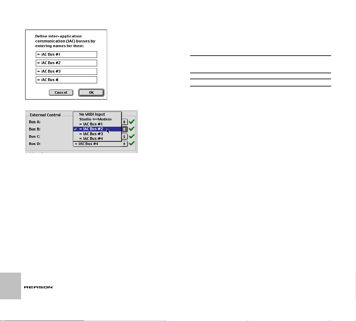
4. Save your OMS Studio Setup.
The OMS IAC port naming dialog.
Selecting IAC busses in Reason’s MIDI Preferences.
Setting up communication between two applications
Proceed as follows:
1. Open the OMS MIDI Setup dialog in OMS Setup and make sure that
“Run MIDI In Background” is enabled.
2. Launch Reason.
It is important that you launch Reason after making changes to OMS, or
the changes you have made will not be available.
3. Set up the other program so that it transmits MIDI to an OMS IAC
port.
4. In Reason, open the MIDI section of the Preferences dialog.
5. Open the MIDI input pop-up for the MIDI Input port(s) that should receive the incoming MIDI, and select the IAC port that you set up in
step 3.
Note that the Sequencer Port only receives MIDI on one selected channel at a time.
Sending MIDI Data from another Application
under Windows
To send MIDI from another application installed on the same computer as
Reason, you need to install HLD (Hubi’s Loopback Device) which is included
on your program CD.
! Note that there are other MIDI routing utilities available apart from
HLD. These may work just as well, so if you have such a utility already installed you could try using that instead.
! HLD will not run under NT/2000.
➜ To install, locate the folder “HLD” on your program CD, open the
“How to install HLD.hlp” file inside the folder, and follow the instructions given.
During the final stage of the installation process you can activate as
many buses as you need (up to four). When you are done, a computer
reboot is required.
Setting up communication between two applications
Proceed as follows:
1. Launch Reason.
2. Set up the other program so that it transmits MIDI to a HLD port (by
default named “LB” plus a number).
3. In Reason, open the MIDI section of the Preferences dialog.
42
ROUTING MIDI TO REASON
Page 45
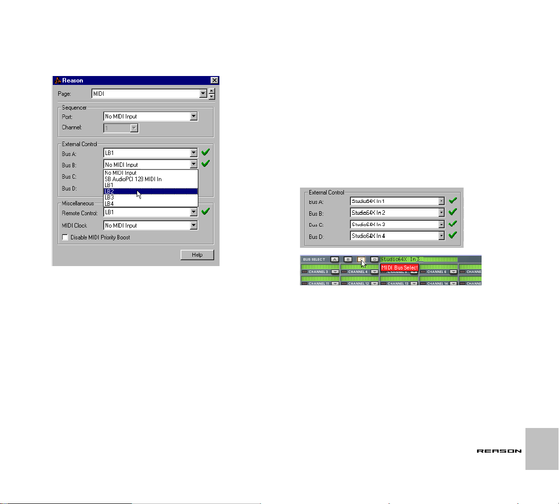
4. Open the MIDI input pop-up for the MIDI Input port(s) that should receive the incoming MIDI, and select the LB port that you set up in
step 3.
Note that the Sequencer Port only receives MIDI on one selected channel at a time.
Selecting a HLD port.
Controlling Devices directly via MIDI
Routing MIDI to Devices
Depending on your MIDI interface, up to four separate ports, each with 16
channels, can be routed to Reason’s External Control inputs. The following
applies regarding setting up the External Control buses:
➜ One port/device can be routed to each separate Bus input.
Simply select the port/device using the appropriate Bus pop-up menu in
the External Control section. One port/device can be routed to several
Bus inputs.
➜ When you have routed several MIDI ports/devices to corresponding
External Buses, you use the Bus Select switch in the MIDI In Device
to select a Bus (A-D) for editing the channel to device routing etc.
If you would like to use an external sequencer to control Reason, there are
basically two scenarios that could apply:
➜ You have a “stand-alone” hardware sequencer or sequencer soft-
ware installed on another computer.
In this case, you should route the MIDI output from the sequencer (or the
MIDI interface on the “other” computer) to the MIDI input on the interface
connected to Reason. You should choose the External Control bus inputs for the incoming MIDI. This data is then routed to devices via Reason’s MIDI In device.
➜ You have sequencer software installed on the same computer as
Reason.
This requires the “OMS IAC Driver” under MacOS, or Hubi’s Loopback
Device (or similar) under Windows, as explained in the previous section
of this chapter.
ROUTING MIDI TO REASON
43
Page 46

➜ If you want to manually play (i.e not recorded MIDI data) Reason de-
vices in real time from inside another sequencer program, MIDI thru
must be activated.
MIDI thru is when incoming MIDI is echoed out via the MIDI output. If you
don’t know how to do this, refer to the program’s documentation. You will
also need to make sure that the other application is “thruing” it’s data to
the correct MIDI port and on the right MIDI channel.
Bypassing the sequencer completely
It is possible to use Reason devices purely as “sound modules”, bypassing
the Reason sequencer completely. To do this, you should use the External
Control busses to receive MIDI, and deselect the Sequencer port in the Preference dialog.
Once you have set up communication between Reason and the other device
or application, you can hide the sequencer from view, by clicking the “maximize rack” button at the top of the rack’s vertical scrollbar.
Sending Controller Data via MIDI
It is possible to send controller data from an external sequencer to control
Reason parameters. Just set up your external device to transmit the correct
MIDI controller messages on the right MIDI channel.
To find out which MIDI Controller number corresponds to which control on
each device, please see the “MIDI Implementation Charts.pdf” document.
Once you have located the controller numbers and set everything up, you
can record and edit the controller data in the external sequencer as you normally do, and the Reason parameters will react correspondingly.
✪ Do not confuse Remote Control and direct MIDI control. MIDI Re-
mote allows you to map any MIDI Controller to any control on the
front panel, but is primarily intended for “live” tweaking of parameters during playback.
44
Recording Pattern changes
As specified in the MIDI Implementation, MIDI Controller #3 can be used to
switch patterns in a device. However, pattern changes activated this way occur immediately (not at the end of the bar), which may or may not be what
you prefer.
Please see page 8 for information on recording and editing pattern changes.
ROUTING MIDI TO REASON
Page 47

USING REASON AS A REWIRE SLAVE
4
Page 48

About this Chapter
This chapter describes how to use Reason as a ReWire slave, that is with
Reason delivering audio to another ReWire compatible application. It does
not deal with using ReBirth and Reason together; that is described on page
156.
Why use Reason with ReWire?
While Reason is a complete music tool in its own right, you might want to add
other elements to the music, such as:
• Vocals.
• Instrumental recordings.
• Hardware synthesizers (controlled via MIDI).
Connecting Reason to another application allows you to do just this, integrate your Reason songs with any other type of music, external MIDI and
acoustic recordings. By recording Reason onto audio Tracks in an audio sequencer you can also continue processing your Reason tracks with other internal and external effects.
Introducing ReWire!
To make this integration between two audio programs possible, Propellerhead Software has developed ReWire. This technology provides the following possibilities and features:
In ReWire version 1
• Real time streaming of separate audio channels, at full bandwidth,
into another audio program.
• Automatic, sample accurate, synchronization between the audio in
the two programs.
• The possibility to have the two programs share one sound card.
• Linked transport controls that allows you to play, rewind etc, from
either program.
• Less total system requirements than when using the programs together in the conventional way.
In ReWire 2
A number of features were added in Reason version 2. The following are the
most important:
• Up to 256 audio channels (previously 64).
• Bi-directional MIDI communication of up to 4080 MIDI channels (255
devices with 16 channels each)
• Automatic querying and linking features that (among other things)
allow a host to display the slave’s devices, controllers, drum
sounds etc. by name.
About ReWire 2
As of this writing there were no applications other than Reason supporting
ReWire 2. Hence, as we write this, teaming up Reason with another program
would only give you the features of ReWire version 1.
This chapter describes the ReWire version 1 feature set. As ReWire 2 implementations will start to appear in other audio applications we will post updated information on our web site, www.propellerheads.se.
How Does it Work?
Basically the key to ReWire is the fact that Reason is divided into three components:
• The Reason application.
• The Reason Engine (a DLL on the PC and a Shared Library file on
the Macintosh)
• ReWire (also a DLL on the PC and a Shared Library on the Macintosh).
ReWire and the Reason Engine are common resources to the two programs
(the other application and Reason) that generate the audio and passes it
onto the other audio application.
Terminology
In this text we refer to Reason as a ReWire slave and the application receiving audio from Reason (Steinberg Cubase, Emagic Logic Audio and Mark of
the Unicorn Digital Performer for example) as the host application.
About System Requirements
To run Reason together with another audio application of course raises the
demands on computing power. However, adding ReWire to the equation
does not in itself require a more powerful computer. On the contrary, it is
likely that ReWiring two programs requires less power than for example running them with one audio card each.
46
USING REASON AS A REWIRE SLAVE
Page 49

Still, you should be aware that running two powerful audio applications on
one computer will require a fast processor and most of all a healthy amount
of RAM.
Launching and Quitting
When using Rewire, the launch and quit order is very important:
Preparations for Using ReWire - Macintosh only
When you use ReWire, some of the system resources normally occupied by
Reason are “transferred” to the other audio application: More specifically, the
RAM required for loading samples in Reason, must now be provided by host
application instead. Therefore, when using ReWire we recommend you to
make the following changes to your memory settings for the two programs
(for details, see your Macintosh manual):
1. If you have raised the maximum memory setting in Reason (to be
able to use more samples) lower it back to the recommended value,
but make a mental note of how much it was set to.
2. Raise the Maximum memory for the host application by at least the
amount that you just lowered for Reason.
Launching for normal use with ReWire
1. First launch the host application.
2. Then launch Reason.
Quitting a ReWire session
When you are finished, you also need to Quit the applications in a special order:
1. First quit Reason.
2. Then quit the host application.
Launching the host application for use without Reason/
ReWire
If you don’t plan to run Reason, just launch the host application as usual. We
recommend that you then also deactivate all ReWire channels if required
(see the relevant section for your program, below). But this is not completely
critical, ReWire does not use up very much processing power when it isn’t
used.
Launching Reason for use without the host application
If you want to use Reason as it is, without ReWire, just launch it as you normally do.
Launching both programs without using ReWire
We don’t know exactly why you would want to run Reason and a Rewire host
application at the same time on the same computer, without using ReWire,
but you can:
1. First launch Reason.
2. Then launch the host application.
You may get a warning message in the host application, regarding ReWire,
but you can safely ignore it. Please also note that the two programs now
compete for system resources such as audio cards, just as when running either with other, non-ReWire, audio applications.
USING REASON AS A REWIRE SLAVE
47
Page 50

Steinberg Cubase VST
Cubase Versions
In this description we assume you are using Cubase VST 5.0 on the MacOS
or Windows platforms.
! For Cubase VST under Windows, please make sure you use 5.0rc2.
Earlier versions have some technical problems with ReWire connections.
OMS – Very Important information for MacOS
Users!
l If you have OMS installed, Cubase VST must be set to use OMS as well.
➜ The OMS Compatibility setting in the MIDI System Setup dialog
must be set to “IN & OUT”!
➜ “Run MIDI In Background” must be enabled in the OMS MIDI Setup!
Activating ReWire Channels in Cubase VST
3. If desired, double click on the labels in the right column, and type in
another name.
This is the label that will be used in VST to identify the ReWire channel.
48
! Do not deactivate Play in Background (on the Options menu in Cu-
base VST). If you do, the communication between the two programs
will be lost.
To activate the desired inputs from Reason, in Cubase VST, proceed as follows:
1. Pull down the Panels menu and select ReWire.
2. Click on the green buttons to activate/deactivate the desired channels.
The 64 channels correspond to the 64 audio inputs on the Hardware Device in Reason. Please note that the more ReWire channels you activate,
the more processing power is required.
USING REASON AS A REWIRE SLAVE
The ReWire window in Cubase VST. Here, four channels are activated.
4. Connect devices in Reason to the activated channels on the Hardware Device and the audio will appear in the Mixer in Cubase VST
(se below).
Page 51

How the ReWire Channels are handled in
Cubase VST
When you activate ReWire channels in the ReWire window in VST, as described above, new channels are added to the VST Channel Mixer.
A few ReWire channels in the VST Channel Mixer.
These channels have the following properties:
➜ The ReWire channel strips are red and appear between regular
channels and group channels.
➜ Stereo outputs from Reason appear as stereo channels in Cubase
VST.
➜ The name of the ReWire channel is printed at the bottom of each
strip, for identification.
➜ These channels are identical to regular VST audio Channel Mixer
strips, except that they have no input. That is, they have all the fx,
EQ, bussing and automation facilities provided by regular hard disk
recording channels.
➜ For information about how to set levels, panning, EQ, fx and bus-
sing, and how to create automation, see the Cubase VST documentation.
USING REASON AS A REWIRE SLAVE
49
Page 52

Emagic Logic Audio
In this description we assume you are using a version of Logic Audio that is
later than 4.6.
Activating ReWire Channels in Logic Audio
To activate the desired inputs from Reason, in Emagic Logic Audio, proceed
as follows:
1. Open the Audio Mixer window from the Audio menu.
Locate the first channel that you want to use for ReWire input and select
it by clicking at its name at the bottom of the channel strip.
2. In the inspector to the left, pull down the “Cha” menu and select the
desired ReWire input.
In the list that appears, all ReWire inputs are listed one after the other.
This list does not display the name of the application, so if you have more
than one ReWire application installed (for example both Reason and ReBirth) be careful to select the correct input.
3. Continue to select more channels and activate ReWire inputs for
these.
Logic Audio presents all ReWire inputs as mono, so to set up a stereo
pair, like the Left and Right outputs from Reason you need to use two
channels.
4. Connect devices in Reason to the corresponding channels on the
Hardware Device and the audio from these outputs will appear in
the Mixer in Emagic Logic.
How the ReWire Channels are handled in
Emagic Logic
When you activate ReWire channels in Logic Audio, as described above,
channels in the Audio Mixer will play the audio coming in via ReWire.
These channels have the following properties:
➜ Just above the pan control you can see the name of the ReWire in-
put.
➜ These channels are identical to regular audio channels. That is,
they have all the fx, bussing and automation facilities provided for
regular hard disk recording channels.
➜ The ReWire channels are all in mono. To set up a stereo pair, use
two adjacent channels. If you want to make identical settings for the
two channels (for example perform a stereo fade), select both channels by holding down [Shift] and move the desired control on either
of them.
➜ For information about how to set levels, panning, EQ, fx and bus-
sing, and how to create automation, see the Logic Audio documentation.
50
The ReWire channels as they appear in Emagic Logic. Here, the stereo channels L
and R are connected to audio channel 1 and 2 in Logic’s mixer window.
USING REASON AS A REWIRE SLAVE
Page 53
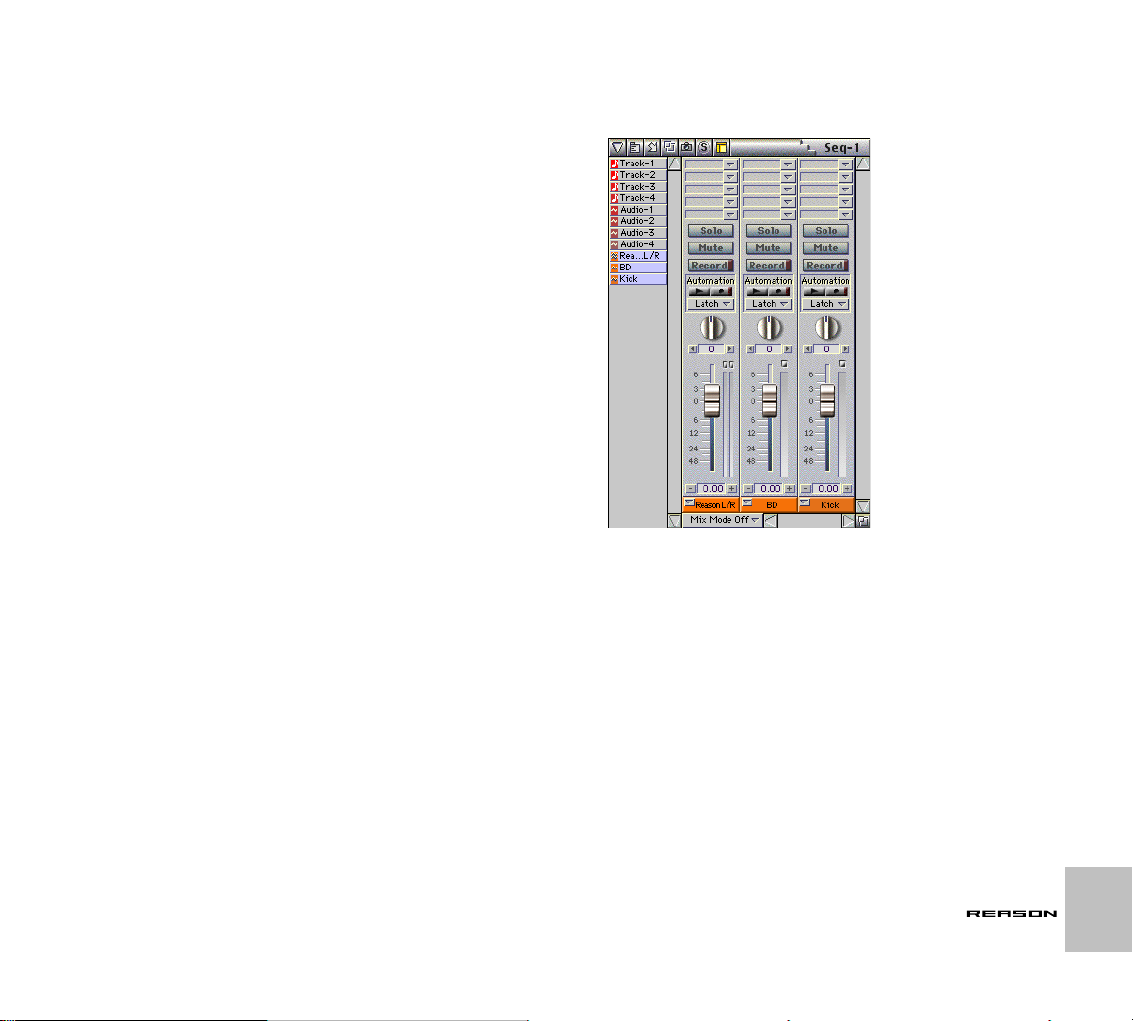
Mark of the Unicorn Digital Performer
Performer Versions
In this description we assume you are using Digital Performer version 2.72 or
later.
OMS
Since Reason requires OMS we recommend that you set up Digital Performer to also use OMS. In that way you can for example use OMS’s IAC
feature to send MIDI between the programs.
Activating ReWire Channels in Digital Performer
To activate the desired inputs from Reason, in Digital Performer, proceed as
follows:
1. Make sure you have the Tracks window up on screen.
2. Create as many audio tracks as you need ReWire inputs. For each
one decide whether you want it to use a mono or stereo voice.
For example, you might want to set the track assigned to the Left/Right
output in Reason to use a stereo voice and other tracks to use mono
voices. Note that you can always add or remove channels later as will,
the system is completely dynamic.
3. Pull down the Input menu for a track and select the desired Reason
input.
4. Click the record enable button for the track(s).
5. Connect devices in Reason to the corresponding channels on the
Hardware Device.
Now when you play back, the audio from Reason will appear on the corresponding voices in Digital Performer.
Here the Digital Performer Mixing Board is displayed with three Reason inputs
selected, one stereo and two mono.
How the ReWire Channels are handled in Digital
Performer
When you set up tracks to receive audio from ReWire, as described above,
the corresponding tracks are added to the track list in the Mixing Board window.
➜ The tracks have generic names by default. to rename them hold
down [Option] and click on the name at the bottom of the channel
strip.
➜ These channels are identical to regular audio channels. That is,
they have all the fx, bussing and automation facilities provided for
regular hard disk recording channels.
➜ For information about how to set levels, panning, EQ, fx and bus-
sing, etc, see the Digital Performer documentation.
USING REASON AS A REWIRE SLAVE
51
Page 54

Using the Transport and
Converting ReWire
Tempo Controls
Basic Transport Controls
When you run ReWire, the transports in the two programs are completely
linked. It doesn’t matter in which program you Play, Stop, Fast Forward or
Rewind. Recording, however, is still completely separate in the two applications.
Loop Settings
The Loop in Reason and the corresponding feature (Loop, Cycle etc) in the
host application are also linked. This means that you can move the start and
end point for the Loop/Cycle or turn the Loop/Cycle on/off in either program,
and this will be reflected in the other.
Tempo Settings
As far as tempo goes, the host application is always the Master. This means
that both program will run in the tempo set in the host application.
However, if you are not using automated tempo changes in the host application, you can adjust the tempo on the transport in either program, and this will
immediately be reflected in the other.
! If you are using the automated tempo changes in the host applica-
tion, do not adjust the tempo on the Reason transport, since that
tempo the doesn’t have any effect on playback!
MIDI Control With ReWire
If you are using a host application that is not Rewire 2 compatible, you will
need to send MIDI via OMS IAC (MacOS) or a MIDI routing utility such as
HLD (Windows) This is described on page 41.
Channels to Audio Tracks
If you want to “convert” your ReWire channels into hard disk tracks, use the
facilities in your host application. Basically there are two ways that this can
be done. Exactly which one applies to you depends on which type of host application you are using:
➜ Record the audio in real time onto audio tracks in the host applica-
tion.
➜ Export your song as an audio file, by using a feature named Export
Audio or similar in the host application.
See the host application documentation for details.
Synchronization
All synchronization to other equipment is handled from the host application,
not Reason. In fact there are no special synchronization issues. All that is
said in the host application’s documentation about synchronizing audio channels is true for ReWire channels as well.
52
USING REASON AS A REWIRE SLAVE
Page 55

MIDI AND KEYBOARD REMOTE CONTROL
5
Page 56

Introduction
MIDI Remote Mapping
It is possible to assign computer keyboard commands and/or MIDI controller
messages to most Reason device parameters or functions. Both methods allow you to use a “learn” function to instantly assign the parameter knob,
slider or button to a keyboard command or a controller on an external device.
If you want to control one or several Reason parameters in real time from an
external MIDI device, you can use MIDI Remote Mapping. The external device could be a dedicated MIDI performance controller, for example.
Setting Up
! If you are using a single MIDI interface with only one MIDI Input,
there are certain restrictions to how you can use MIDI Remote Mapping. See “Example MIDI Setups” below for an explanation.
To set up Reason for MIDI Remote Mapping, proceed as follows:
1. Open the Preferences dialog from the Edit menu and select the MIDI
page.
2. Open the Remote Control pop-up in the Miscellaneous section, and
select your MIDI input.
This should be a preferably be a separate port that you “dedicate” to
sending controller messages, see below.
3. Close the Preferences dialog.
54
MIDI AND KEYBOARD REMOTE CONTROL
Page 57

Example MIDI Setups
There are several possible variables when it comes to what type of MIDI
setup you are using. Please read on.
“Ideal” Setup
The ideal setup is a computer with two MIDI interfaces or one MIDI interface
with multiple, separate inputs, a MIDI keyboard used for playing/recording
and a separate MIDI Controller device (“fader box”) used for remote control.
1. Connect your MIDI keyboard to one MIDI Input.
2. Connect your MIDI remote device to the other MIDI Input.
3. Open the Preferences – MIDI dialog and set things up so that the
MIDI keyboard is used for playing and the fader box is used for MIDI
Remote control.
If You are Using a Single MIDI Interface with one MIDI Input
only
In this scenario we assume you have your MIDI keyboard and external MIDI
controller connected to the same MIDI Input on your computer. In this case
it’s a little bit trickier to get things to work correctly. Here’s the problem:
If you are using the sequencer input for playing a device, the device will react
to MIDI controller messages via this input, since all devices are always set up
to react to MIDI controller messages (see page 197 for details).
Now, if you happen to set things up so that a control on a device reacts to the
same MIDI Controller message as is used for remote control of another control (maybe even on another device) both controls will move simultaneously
on screen!
The solution is to separate things via MIDI Channel messages. Proceed as
follows:
1. If you are using the MIDI sequencer input to play your devices, open
the Preferences - MIDI dialog and make a note of which MIDI Channel is used for sequencer input.
2. If you are instead using one of the direct MIDI buses A to D, check
the Hardware Interface to find out which MIDI Channels are already
taken by devices in the rack.
3. Set up your MIDI Controller (that you plan to use for MIDI Remote
control) to transmit on any MIDI channel that is not already occupied (as described above).
4. When you then set up MIDI remote Control, only use the MIDI Channel on which your MIDI Controller is now set to transmit on.
This will ensure that remote control doesn’t conflict with other MIDI.
If you only have one MIDI Device
If you only have one MIDI Device that you plan to use both for playing/recording and for remote control, there are severe restrictions. Actually there ‘s only
one sensible way to avoid conflicts.
1. Open the “MIDI Implementation Charts.pdf” document.
This can be found in your program folder.
2. Make a note of the controller numbers that are not used for direct
control of any device at all.
3. Set up your MIDI remote control so that it only uses these unused
MIDI Controller numbers.
! Please note that you can only assign a MIDI Controller number for
remote control of one parameter at a time. If you try to assign a second parameter to a MIDI Controller number already used, the previously assigned parameter is overridden by the new one.
Enabling MIDI Remote
To enable MIDI Remote, select “Enable MIDI Remote Mapping” from the Options menu.
MIDI AND KEYBOARD REMOTE CONTROL
55
Page 58

Editing MIDI Remote Mapping
1. To get an overview of which parameters are MIDI remote controllable select “Edit MIDI Remote Mapping” from the Options menu.
When done, each device you select will show a green arrow symbol beside every parameter that can be assigned a MIDI remote.
A section of a mixer with MIDI Remote enabled.
2. If you click on a assignable parameter, a dialog appears allowing
you to select a MIDI controller (or a Note number) to control that parameter.
Note numbers function exactly like Keyboard remote - they can only control on/off or min/max values (see page 57).
4. Simply turn the knob (or slider etc.) that you wish to use to remote
control the parameter.
The “MIDI Received” field momentarily flickers as you turn the knob, and
then the dialog shows the controller number and the channel it is transmitted on.
5. Click “OK” to exit the dialog.
The selected parameter now has a tag, displaying the controller number,
and the MIDI channel used.
6. To exit Edit MIDI Remote Mapping mode, deselect it from the Options menu.
You do not always have to use this method - see below.
About the two Edit MIDI Remote Mapping Modes
If Edit MIDI Remote Mapping is enabled (ticked) on the Options menu, assigned parameters are “tagged”, and the arrow indicators show the assignable parameters. In this mode, however, you cannot operate Reason
normally, as every parameter you click on will open the MIDI Remote dialog.
The Edit mode is primarily for overview of available parameters and the current assignments.
➜ Another way to assign keyboard remote commands is to have “Edit
MIDI Remote Mapping” deselected on the Options menu, and to
simply [Ctrl]-click (Mac) / right-click (PC) the parameter you wish to
remote control.
This opens a pop-up menu, where one of the options will be “Edit MIDI
Remote Mapping”. Selecting this opens the MIDI Remote dialog. Thus,
you do not have to select Edit mode from the Options menu if you already
know that a parameter is free and assignable.
56
The MIDI Remote dialog.
3. Make sure that the “Learn from MIDI Input” box is ticked.
MIDI AND KEYBOARD REMOTE CONTROL
Page 59
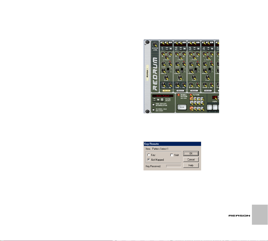
Keyboard Remote
Assigning keyboard remote commands is very similar to MIDI remote mapping. However, as there is no MIDI involved, there is no special setting up required. Keyboard commands can be assigned the same parameters as when
using MIDI remote mapping, but the functionality differs in one central aspect:
➜ Keyboard Remote commands can only be used to toggle on/off or
min/max values for an assigned parameter.
Hence, if you assign a keyboard remote command for a knob, slider or spin
control, it will only switch between the minimum and maximum values for that
parameter. The only exception to this are the multi-selector buttons used for
various parameters such as envelope destination, for example. These will
cycle through the available options when using keyboard remote.
Enabling Keyboard Remote
To enable Keyboard Remote, select “Enable Keyboard Remote” from the
Options menu, or press [Command]+G (Mac) or [Ctrl]+G (PC).
Editing Keyboard Remote
➜ To get an overview of which parameters are remote controllable se-
lect “Edit Keyboard Remote” from the Options menu.
When done, each device you select will show a yellow arrow symbol beside every parameter that can be assigned a keyboard remote.
A section of a drum machine with Keyboard Remote enabled.
➜ If you click on a assignable parameter, a dialog appears allowing
you to select a key command for that parameter.
You may use any key except the Space bar, Tab, Enter or the Numeric
keypad (which is reserved for Transport functions) or a combination of
[Shift] + any key (with the same aforementioned exceptions).
The Keyboard Remote dialog.
➜ Simply press the key (or key combination) you wish to use to re-
mote control the parameter.
The “Key Received” field momentarily indicates that it is “learning” the
keystroke(s), and then the dialog displays the name of the key you have
pressed. If [Shift] was used, the box beside the word Shift in the dialog is
ticked.
MIDI AND KEYBOARD REMOTE CONTROL
57
Page 60

About the two Edit Keyboard Remote Modes
If Edit Keyboard Remote is enabled (ticked) on the Options menu, assigned
parameters are “tagged”, showing the remote key for that parameter. In this
mode, however, you cannot operate Reason normally, as every parameter
you click on will open the Key Remote dialog. This mode is primarily for overview of available parameters and the current assignments.
➜ Another way to assign keyboard remote commands is to have “Edit
Keyboard Remote” deselected on the Options menu, and to simply
[Ctrl]-click (Mac) / right-click (PC) the parameter you wish to remote
control.
This opens a pop-up menu, where one of the options will be “Edit Keyboard Remote”. Selecting this opens the Key Remote dialog. Thus, you
do not have to enable/disable Edit mode from the Options menu if you
know that a parameter is assignable.
! If you try to assign a Remote Key that is already in use, you will get
an alert asking if you wish to change the current assignment.
Saving Remote Setups
MIDI or Keyboard Remote setups are always stored with the song. But perhaps you wish to be able to recall this setup for use in a new song, or permanently use a specific remote setup.
➜ This could be done by saving a song document containing all the
devices that are affected by the remote setup together with the related Key or MIDI mapping, but without any sequencer data.
This song document could then be used as a starting point for any new
song, by simply loading it, and immediately using “Save As” to save it under a new name.
58
MIDI AND KEYBOARD REMOTE CONTROL
Page 61

SYNCHRONIZATION
6
Page 62
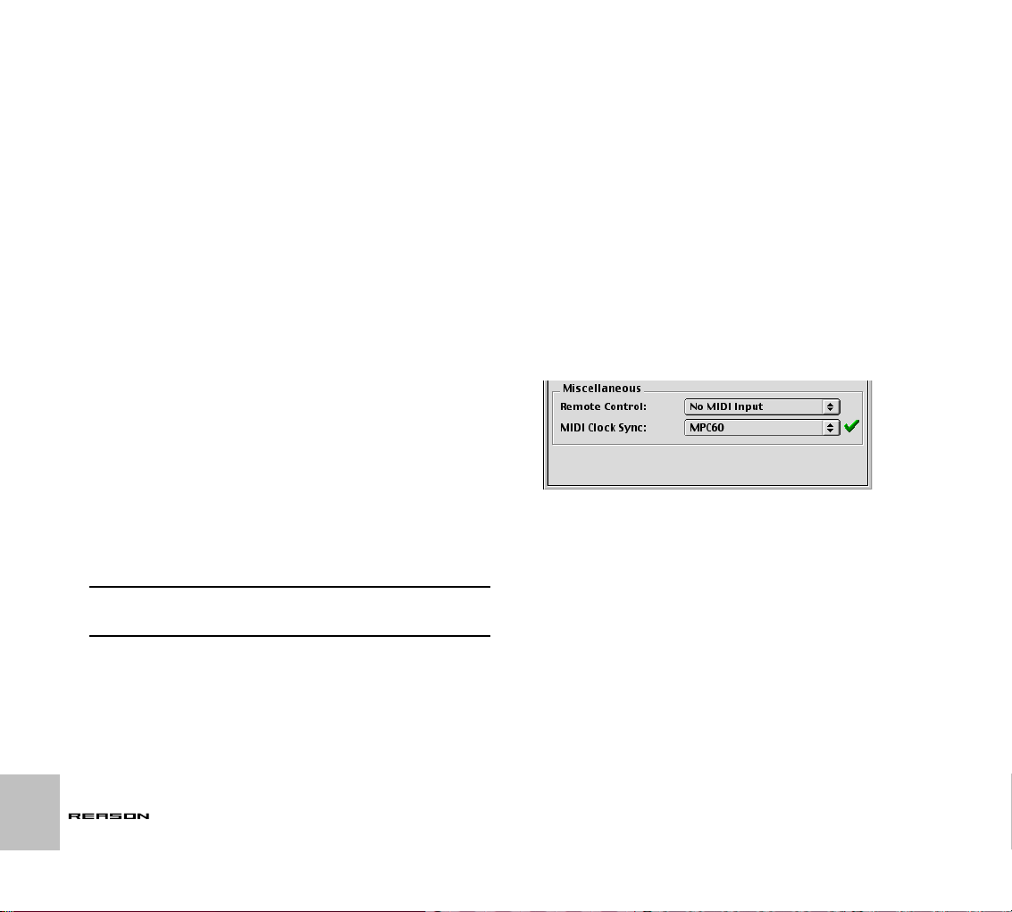
ReWire users – Read
Slaving Reason to an
This!
This chapter does not apply to users of ReWire. If you are using Reason together with a ReWire compatible application, ReWire handles all synchronization issues for you, automatically. See the ReWire chapter for details.
What is Synchronization and MIDI Clock?
Synchronization, in this context, is when you make Reason play at the same
tempo as another device; where both start, stop and can locate to certain positions, together. This is done by transmitting MIDI Clock signals between
Reason and the other device. MIDI Clock is a very fast “metronome” that can
be transmitted in a MIDI cable. As part of the MIDI Clock concept there are
also instructions for Start, Stop and locating to sixteenth note positions.
You can set up synchronization between Reason and hardware devices
(tape recorders, drum machines, stand alone sequencers, workstations etc.)
and other computer programs running on the same or another computer.
Master/Slave
In a synchronized system there is always one master and one or more
slaves. In our case, the master is the one that controls the tempo. In other
words, it is only the tempo setting on the master device that is of any relevance, since the slaves slavishly follow the master's tempo.
➜ Reason always acts as a slave. That is it receives MIDI Clocks, it
never transmits them.
! Before you create any serious projects that require sync, try out the
features described below and check out “Synchronization Considerations” on page 117.
External Device
This example assumes that you have an external device, such as a drum
machine, hardware sequencer, another computer, tape recorder etc., that
transmits MIDI Clocks that you want to synchronize Reason to.
1. Connect a MIDI Cable from the MIDI Out on the other device to a
MIDI In on the computer running Reason.
2. Set up the other device so that it transmits MIDI Clock signals to the
MIDI Out you just connected to the computer running Reason.
3. In Reason, pull down the Edit menu and open the Preferences dialog. Select the MIDI page.
4. Pull down the MIDI Clock pop-up and select the MIDI Input to which
you connected the MIDI cable from the other device.
On the Macintosh, if you do not understand which Input this is, or if that
MIDI input doesn’t appear in the list, consult your OMS documentation for
information on MIDI interfaces, MIDI ports and naming.
Reason Mac set up to sync to MIDI Clock coming in from a MPC-60 drum machine
connected to an external MIDI interface.
60
SYNCHRONIZATION
Page 63

Under Windows, if you can’t find the MIDI Input you want to use, there is either something wrong with the installation of the interface, or some other program is holding on to it. Consult the documentation for the MIDI interface, the
other program and Windows, for more information.
Reason Windows set up to sync to MIDI Clock coming in via the MIDI interface on an
AWE 64 card.
5. Close the dialog.
6. Activate MIDI Clock Sync from the Options menu in Reason.
This can also be set on the Transport panel.
7. Activate playback on the other device.
Reason will start playing ‘in sync’ with it and the Sync LED on the Transport will light up.
Slaving Reason to Another Program on the Same Computer
This sections describes how to synchronize Reason to another application
running on the same computer. This text is based on the following assumptions:
• Under MacOS, that the other program has full support for OMS (if
not see page 62) and that you have read and understood the instructions on MIDI via OMS in general, described in the chapter
“Routing MIDI to Reason”.
! Note that this makes the two programs play at the same time, that
is, they both “run” when you “hit play”. It does not means they can
both play audio at the same time. See page 193 for details about
“sharing audio”.
• Under Windows that you have read and understood the instructions
on using a MIDI routing utility such as Hubi’s Loopback Device, as
described on page 42.
Proceed as follows:
1. Set up the other program, so that it transmits MIDI Clock to Reason:
Under MacOS this is done by selecting the OMS IAC port. Under Windows this is done by selecting one of the MIDI routing utility ports.
2. In Reason, pull down the Edit menu and open the Preferences dialog. Select the MIDI page.
SYNCHRONIZATION
61
Page 64

3. Pull down the MIDI Clock pop-up and select the corresponding MIDI
routing utility port (IAC, HLD etc.).
Windows: Reason set up to sync to MIDI Clock coming in via HLD port number 1.
MacOS: Slaving Reason to a non-OMS Program
If the MIDI program you use does not support the common standard for MIDI
on Macintosh computers, OMS, you can still set up synchronization, but this
requires two MIDI interfaces, each connected to one of the serial ports on
your computer.
1. Set up OMS so that it uses only one of the MIDI interfaces installed.
2. Set up the other application so that it uses the other MIDI interface.
3. Connect a MIDI cable from an output on the “other application” interface to an input on the OMS-controlled interface.
4. Set up the other application so that it transmits MIDI Clock signals
to the output you connected the cable to.
5. In Reason, pull down the Edit menu and open the Preferences dialog. Select the MIDI page.
6. Pull down the MIDI Clock pop-up and select the MIDI Input to which
you connected the MIDI cable from the other device.
On the Macintosh, if you do not understand which Input this is, or if that
MIDI input doesn’t appear in the list, consult your OMS documentation for
information on MIDI interfaces, MIDI ports and naming.
7. Close the dialog.
8. Activate MIDI Clock Sync from the Options menu in Reason.
9. Activate playback on the other device.
Reason will start playing ‘in sync’ with it and the Sync LED on the Transport will light up.
62
Mac OS: Reason set up to sync to MIDI Clock coming in via OMS IAC.
4. Close the dialog.
5. Activate MIDI Clock Sync from the Options menu in Reason.
6. Activate playback on the other device.
Reason will start playing ‘in sync’ with it and the Sync LED on the Transport will light up.
SYNCHRONIZATION
Page 65

Synchronization Considerations
Adjusting for Latency
Latency compensation (MacOS version)
Because of the latency problem described on page 194, you might need to
adjust Reason’s playback in relation to the sync master, so that they are in
perfect time. The tempo will not differ between the two, but Reason might
play ahead or behind the other application. You might need to adjust this.
However, this is something you only need to do once. The setting is stored
with your other preferences, so you don’t need to adjust it again.
Proceed as follows:
1. Set up the other application so that it generates a solid click, on for
example quarter or eighth notes, preferably with a special sound on
the downbeat.
This click can either come from an internal metronome or from a MIDI
source. If you use a MIDI source, make sure you pick one that has solid
MIDI timing.
2. Set up Reason so that it plays a similar rhythm as the other application.
You might for example use the Metronome or Redrum drum computer for
this.
3. Start the two applications in sync.
4. Make sure you hear both applications at approximately equal level.
5. Open the Preferences dialog in Reason and select the Audio page.
6. Trim the “Latency compensation” setting until the “clicks” from the
both sources sound at exactly the same time.
7. Close the Preferences dialog in Reason.
If Latency Compensation isn’t enough
There might be situation s where you can’t compensate enough in Reason to
make two software applications run in sync. This might especially be true if
the other application is an audio sequencer, that is if it can both record and
playback audio and MIDI.
This problem an indication to the fact that the other application has not been
set up properly and that its audio playback is not in sync with its own MIDI
playback.
! This is not something that you can or should compensate for in
Reason. Instead, follow the instruction included with the other application to make sure its MIDI playback and audio playback or correctly locked to each other.
About the beginning of the Song
Due to the latency phenomenon, described on page 194, Reason needs
some time to correct it’s playback speed when it first receives the Start command. This can be noted as a small glitch in the audio playback, when the
program starts. If this is a problem, you need to insert a couple of empty
measures at the beginning of the Song. Proceed as follows:
1. Set the Left Locator to “1 1 1” and the right Locator to “3 1 1“.
2. Click somewhere in the main sequencer area to move the menu focus to the sequencer.
3. Select “Insert Bars Between Locators” from the Edit menu.
4. Set up the other device/application, so that it also plays two empty
bars at the beginning.
About MIDI Song Position Pointers
MIDI Clock actually consists of five type of messages: The actual clock (the
metronome that establishes the tempo), Start, Stop and Continue commands
and Song Position Pointers. This last type of message contains information
about positions, so that a program for example “knows” where in a Song to
start playback from.
Normally, this ensures that you can locate to any position and activate playback from there. In older devices, Song Position Pointers might not be implemented. This means that you will be able to synchronize properly only if you
start both devices from the absolute beginning of the song.
SYNCHRONIZATION
63
Page 66

About Tempo Changes
Again, due to the latency phenomenon, Reason needs a bit of time to adjust
to changes in tempo. If there are abrupt changes in the MIDI Clock, due to
drastic tempo changes on the master, you will note that Reason will require
up to one measure to adjust itself to the change. How long this actually takes
also depends on the precision of the incoming MIDI Clock. The more precise
it is, the faster Reason can adjust to it.
If this adjustment is a problem, try to use gradual tempo changes rather than
immediate ones.
! When Reason is synchronized to MIDI, there is no Tempo readout.
64
SYNCHRONIZATION
Page 67

OPTIMIZING PERFORMANCE
7
Page 68

Introduction
Optimization and Output
Reason is a program of infinite possibilities. You can create as complex
songs as you like, using endless racks of devices. While this is one of the
most exciting properties of the program it does have a drawback – it means
that you must be careful with how you manage your computer processing
power.
Each device you add to the rack uses up a bit of computer processing power
– the more devices the faster the computer has to be. However, you can set
up your devices to require more or less processing power. For example a
sound on the Subtractor synthesizer that only uses one oscillator and one filter requires much less processing power than one using both dual oscillators
and dual filters.
Samples used in your songs also require RAM - memory - to load properly.
The use of RAM can also be managed, as described at the end of this chapter.
When creating songs for other people, for example for publishing in the Reason song archive (see www.propellerheads.se for more information), you
should do what you can to reduce the requirements for playing back a certain
song, both in terms of processing power and in terms of RAM requirements.
Other users may not have as powerful a computer as you do!
Checking Processing Power
On the transport you will find a meter labelled CPU. This indicates how much
processing power is used at any given moment.
The CPU meter.
The higher this meter goes, the higher the strain on your computer processor. You will note that when your processor is heavily loaded that graphics
will update slower. Finally, when there’s too little power left to create the audio properly, the sound will start breaking up.
Latency
There is s a certain connection between output latency and the demands on
your computer (for more information on latency see page 194):
When your computer doesn’t have enough resources to play back a song,
audio playback will start breaking up. One way of reducing the overhead on
the computer is to raise the latency. There are two ways to do this:
➜ If you are using an ASIO driver, open its control panel (from the
Preferences – Audio dialog) and raise the buffer setting.
This is mainly effective if you are currently using very small buffers, 64 to
256 samples. If the buffers are already big (1024 or 2048 samples) you
will not notice much difference.
➜ If you are using an MME or DirectX driver, adjust the Output Latency
slider in the Preferences – Audio dialog.
✪ Please note that raising these values introduces more delay when
playing devices in real time.
For more information on various driver types, see the chapter “About Audio
on Computers”.
66
OPTIMIZING PERFORMANCE
Page 69

Optimizing Your
Optimizing Songs
Computer System
In this manual we do not have the possibility to give you detailed procedures
for optimizing your computer for maximum power. This is a subject that we
could write complete books on! However, we’d like to share a couple of important tips:
➜ Quit other programs that are running at the same time as Reason.
➜ Remove background tasks on your computer.
This might be any background utilities you have installed as well as networking, background internet activities etc.
➜ Under Windows, make sure you use the latest and most efficient
driver for your audio card.
Generally, ASIO drivers are the most efficient, followed by DirectX and
last MME.
➜ Only work on one Reason document at a time.
Songs that are open in the background do consume some processing
power even though they’re not playing.
➜ Lower the sample rate setting on the Preferences dialog.
While this also reduces sound quality, it is a very quick and convenient
way to try to play a song that your computer otherwise can’t handle.
➜ Make sure your computer display is set to 16-bit colors.
Under Windows, this mode is called “High Color”; under MacOS it is
called “Thousands of colors”.
Below follows things you can check and change to make sure your song
uses as little computer processing power as possible:
Global
➜ Delete unused devices.
If a device isn’t actually doing anything, delete it from the rack.
➜ Use fewer devices.
For example, instead of using several reverbs as insert effects, replace
them all with one, set up as a send effect. By the same token, try to use
one sampler playing several different samples instead of numerous samplers playing one sample each.
➜ Don’t use stereo unless it is required.
For example, if your NN19 sampler or Dr. Rex player is playing mono material, only connect the Left output and leave the Right output unconnected.
Sample Players – NN19, Dr. Rex and Redrum
➜ Only activate High Quality Interpolation when it is required.
Listen to the sound in a context and determine whether you think this setting makes any difference. However, note that on a Macintosh G4, High
Quality Interpolation does not require any more processing power.
➜ If you are playing back a sample at a much higher pitch than it was
recorded at, consider sample rate converting the actual sample file
to a lower sample rate.
This will require an external sample editor with good sample rate conversion facilities.
➜ Try to refrain from using stereo samples.
Filters – Subtractor, NN19 and Dr. Rex
➜ Deactivate filters that are not used.
Observe that if the Cutoff is all the way up or the envelope is set to open
the filter fully, then the filter doesn’t affect the sound. Conserve processing power by disabling the filter altogether.
➜ Use the12dB lowpass filter instead of the 24dB lowpass filter.
See if you can get the same sonic result by using the 12dB filter, since it
uses up less processing power.
OPTIMIZING PERFORMANCE
67
Page 70

Polyphonic Devices – Subtractor, NN19, Dr. Rex
and Redrum
➜ Try making the device play fewer voices.
This can be done for example by lowering the release and setting the Polyphony setting to exactly the maximum number of notes played simultaneously by this device.
✪ Please note that just lowering the polyphony setting has no effect.
Unused voices do not consume processing power.
➜ Try the Low Bandwidth (Low BW) setting.
This will remove some high frequency content from the sound of this particular device, but often this is not noticeable (this is especially true for
bass sounds).
Subtractor
➜ Try avoiding using Oscillator 2 altogether.
If you can create the sound you need with only one oscillator, this saves
considerable amounts of processing power.
➜ Do not use the oscillator Phase mode if you don’t need it.
In other words, set the Oscillator Mode switches to “o”, not “
➜ Do no activate Noise unless required.
➜ Do not activate Filter 2 unless required.
➜ Do not use FM unless required.
In other words, set the oscillator FM knob to “0” and make sure no modulation source is routed to FM.
” or “–”.
*
Redrum
➜ Do not use the Tone feature available on channel 1, 2 and 9.
In other words, make sure the Tone controls and their accompanying Vel
knobs are set to “0” (“twelve o’ clock”).
Mixer
➜ Avoid using stereo inputs when not required.
For example, if your sampler or Dr. Rex player is playing mono material,
only connect it to the Left input on a mixer channel. Leave the Right input
unconnected.
➜ Do not activate EQ unless required.
If a channel doesn’t make use of EQ, make sure it’s EQ button is deactivated.
Reverb
➜ If you are running out of processing power, try the Low Density al-
gorithm.
This uses up much less power than other algorithms.
Send Effects
➜ When you are using mono effects as send effects, you can connect
the effect returns in mono as well (disconnect the cable to Aux Return Right on the Mixer).
This is true for the following effects:
• D-11 Distortion.
• ECF-42 Envelope Controlled Filter.
• COMP-01 Compressor.
• PEQ-2 Parametric EQ.
• DDL-1 Delay (provided the Pan parameter is set to center position).
68
OPTIMIZING PERFORMANCE
Page 71

Songs and Memory Requirements
Songs not only use up system resources in terms of processing power, they
also require RAM (memory) to load at all.
The amount of RAM required for loading a song, is directly proportional to
the amount of samples used in the song. For example, a song only using
Subtractors and effects requires very little RAM.
If you are running out of RAM try the following:
➜ Close other song documents.
All open songs compete for RAM
➜ Under MacOS; raise the memory setting for Reason.
This is done in the FInder by selecting the Reason application and opening the Get Info window.
➜ Under Windows, terminate other applications.
All running application compete for the RAM available in the computer.
➜ Use mono samples instead of stereo.
Mono samples require half the amount of RAM.
➜ Try sample rate converting sample files to a lower sample rate.
Note that this will affect sound quality negatively. Also note that it will require an external sample editor with good sample rate conversion facilities.
OPTIMIZING PERFORMANCE
69
Page 72

70
OPTIMIZING PERFORMANCE
Page 73

TRANSPORT PANEL
8
Page 74
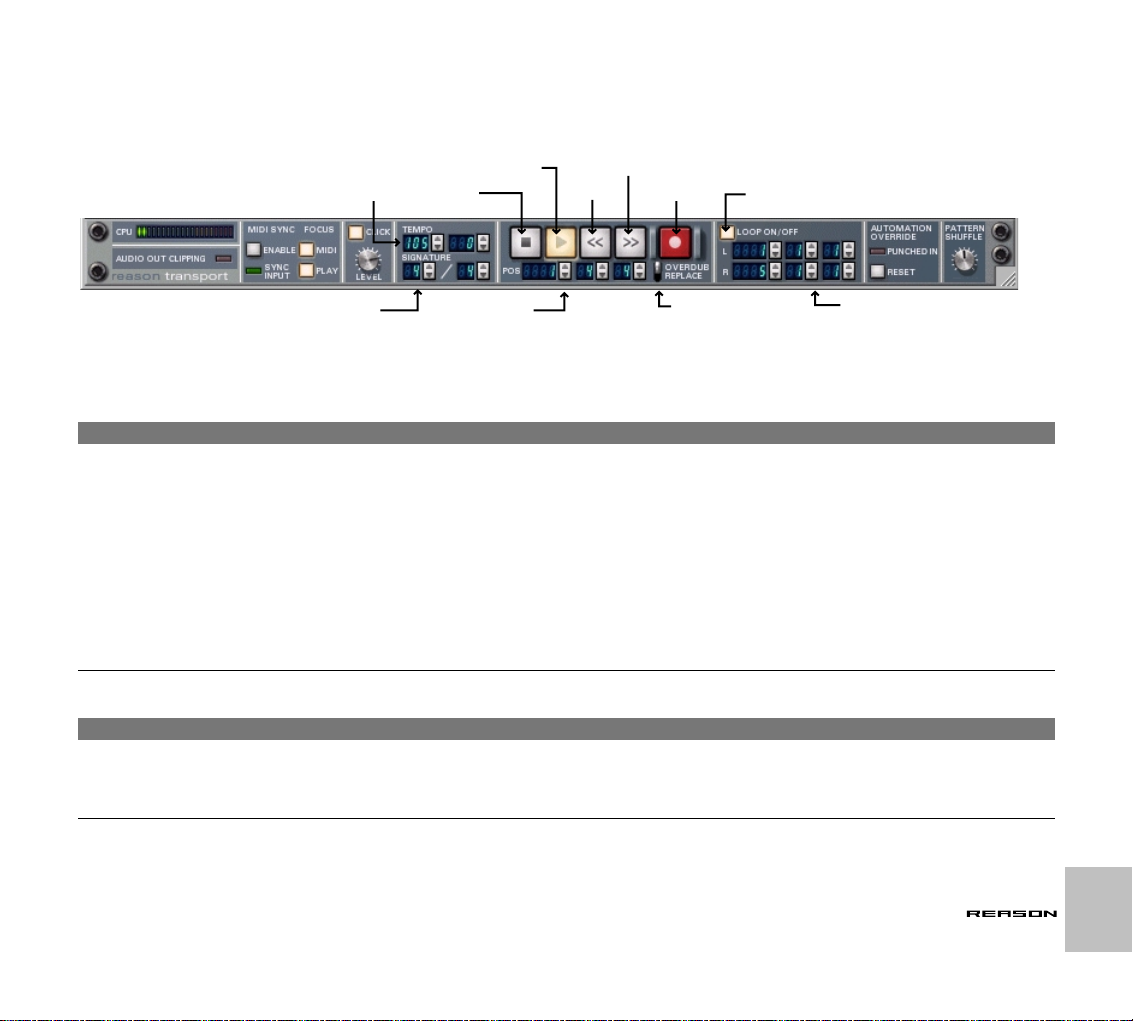
Overview
The transport panel has standard controls for the sequencer transport, but also features controls for setting tempo, metronome click, locator points etc. The
main controls in the central area of the transport panel are as follows:
Tempo
Play
Stop
Rewind
Fast Forward
Record
Loop on/off
Time Signature
Song Position
Overdub/Replace switch
Left and Right Locator
Main Transport Controls
The main transport controls function just like standard controls on tape recorders etc. There are also fixed computer keyboard combinations for the most important transport functions:
Function
|
Stop [0] on the numeric keypad or
Play [Enter] on the numeric keypad Starts playback of the sequencer.
Rewind [7] on the numeric keypad Clicking once moves the position backward one Bar. If you press and hold this button on the transport
Fast Forward [8] on the numeric keypad Clicking once moves the position forward one Bar. If you press and hold this button on the transport
Record [*] on the numeric keypad, or
You can also use the following transport related key commands:
Function
|
Toggle Stop/Play Space bar Switches between stop and play mode.
Go to Left Locator (Loop Start) [1] on the numeric keypad Sets the position to the left locator.
Go to Right Locator (Loop End) [2] on the numeric keypad Sets the position to the right locator.
Key command
|
[Return]
[Command]/[Ctrl]-[Return]
Key command
|
Comments
|
Pressing Stop during playback stops the sequencer. Pressing stop again, sets the position to the left
locator (if this is located before the current position). Pressing stop a third time sets the position to the
start of Bar 1. The Stop button also sends out a “Reset” message, in case of stuck notes or other related problems.
(not using key command) it will start scrolling faster after about 2 seconds.
(not using key command) it will start scrolling faster after about 2 seconds.
Activates “Record ready” mode if sequencer is stopped. If activated during playback it will start re-
cording immediately (“punch in”).
Comments
|
T RANSPORT PANEL
72
Page 75

Tempo and Time Signature
Left and Right Locator Positions
The tempo and time signature settings can be adjusted on the transport
panel. The left tempo field sets the tempo in bpm, and the tempo field to the
right allows you to fine tune the tempo, in steps of 1/1000 bpm.
➜ You can specify any tempo between 1 and 999.999 bpm (beats per
minute).
➜ You can also adjust the tempo (in bpm steps) by using the [+] and
[–] keys on the numeric keypad.
➜ You set the time signature by specifying a numerator (left value
field) and a denominator (right value field).
The numerator is the number of beats per bar, and the denominator governs the length of a beat.
Song Position
The song position in Bars, Beats and 16th notes is shown (in that order) in
the three fields below the transport controls. You can set the positions by using the spin controls.
➜ You can also set the position by double clicking on a Pos value box,
typing in a new position (in the format “Bars.Beats.16th notes”) and
pressing [Return].
If you only type one or two numbers, the remaining numbers will be set to
their lowest values (e.g. type “5” to set the position to “5.1.1”)
The left and right locators are used for several things, like setting the boundaries of a loop or inserting/removing bars. You can set the positions for both
locators by using the spin controls on the transport panel or by double clicking and typing a position value.
Loop On/Off
In loop mode, the sequencer will repeat a section over and over again, during
playback or recording. You specify the section to be looped by setting the left
and right locator.
Overdub/Replace Switch
When recording over a previously recorded section, this switch governs the
following:
➜ In Overdub mode, the new recording is added to whatever was on
the Track before.
➜ In Replace mode, the new recording replaces any previously re-
corded notes.
! Note that controllers and pattern changes aren’t affected by this -
recording controllers will always replace any previously recorded
controller values. However, you may still want to set the switch to
Overdub mode, to avoid accidentally removing some recorded
notes in the area.
T RANSPORT PANEL
73
Page 76
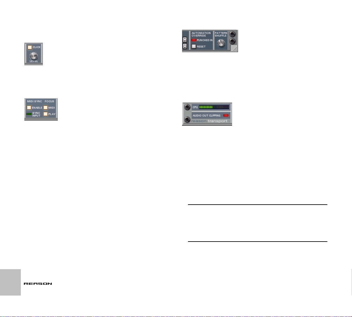
Additional Transport Panel Items
Click
When this is activated, you will hear a click on each beat, with an accent on
the downbeat of each bar. The click is played back during recording and
playback. You can adjust the volume of the click by using the Level knob.
MIDI Sync and Focus
Automation Override
Automation override is activated when you manually “grab” a parameter that
is being automated. If you change the setting of an automated parameter,
the “Punched In” indicator lights up, and the automation data is temporarily
overridden, until you either click the “Reset” button or press stop on the
transport. As soon as you click Reset, the automation regains control.
See also page 7.
Audio Out Clipping Indicator
74
This section of the Transport Panel contains items relating to MIDI sync.
➜ The “Enable” button puts Reason into MIDI sync mode.
The transport controls will be disabled, and Reason will not run unless
MIDI sync data is provided from an external device.
The MIDI and Play Focus buttons relate to how incoming MIDI and MIDI sync
should be handled if there are several open Song documents. If you have
two or more Songs opened, and no MIDI sync is used, the currently selected
Song (the document “on top”) always has MIDI focus. If MIDI Sync is enabled
(which is global for all currently open Song documents), this functionality
changes in the following way:
➜ If both “Play” and “MIDI” are activated for a Song, incoming MIDI
data and MIDI sync will be sent to this Song, regardless of whether
another Song is currently in focus.
➜ If only “MIDI” is activated for Song, and another Song has “Play” fo-
cus, incoming MIDI will be sent to the former and MIDI sync to the
latter (i.e this Song will play back), regardless of which Song is currently in focus.
TRANSPORT PANEL
All signals that are being fed into the Hardware Interface (to your audio hardware’s physical outputs) are monitored for clipping (signal overload) at the
output stage.
If clipping occurs this indicator will light up, and stay lit for several seconds. If
this happens, you should reduce the output level, in one of the following
ways:
➜ If the signals are being sent to your Hardware Interface via a Mixer,
you should reduce the Master output level from the Mixer.
This will ensure that the relative levels of the mix are kept intact. Alternatively, if the current mix doesn’t represent a “final balance”, and the clipping seems to be caused by individual channels in the mixer, you could
also try reducing the output of the connected device(s), or pulling down
the channel faders a bit for the “offending” channels.
! Clipping can only occur in the output stage of the Hardware Inter-
face, not in the Reason mixer or in any other Reason device. However, it is good practice to keep all mixer channel and master levels
as high as possible within the normal range, for best results. For example, having to compensate channel levels by drastically reducing
the Master output to avoid clipping is indicative of the mixer channel levels being set too high.
Page 77

➜ If the Audio Out Clipping indicator lights up, and the signals are be-
ing sent directly (not via a Mixer) to your Hardware Interface, you
can check the meters in the Hardware Interface. If the red segment
of any of these meters are momentarily lit, this indicates at which
output(s) the clipping is occurring.
Reduce the output level of all devices connected to outputs whose
meters show red.
CPU Meter
This bar graph shows the current CPU (processor) load. Note that this measures how much of the total processor power the Reason “audio engine” currently is using up. Graphics, MIDI and the “rest” of the Reason program is
allotted the CPU power not used by the audio engine, so audio always has
priority. See the chapter “Optimizing Performance” for more information.
T RANSPORT PANEL
75
Page 78

76
TRANSPORT PANEL
Page 79

REASON HARDWARE INTERFACE
9
Page 80

Introduction
The Hardware Interface is where you connect Reason with the “outside
world”. This is where MIDI is received, and where audio signals are routed to
ReWire channels or to the physical outputs of your audio hardware. The
Hardware Interface is always present at the top of the rack, and cannot be
deleted. This chapter is meant to serve as a panel reference, describing the
various sections of the device. How to set up your MIDI interface and audio
hardware is described in Getting Started book and in the chapter “About Au-
dio on Computers”.
The Hardware interface is divided into two sections: MIDI In Device and Audio Out.
MIDI In Device
Reason’s Hardware Interface can accommodate up to 64 channels of MIDI,
divided into 4 buses, each with 16 MIDI channels. There are two basic ways
you can route incoming MIDI to Reason devices, which is set in the Preferences - MIDI dialog:
➜ Via the Sequencer.
If you choose this option, the selected track’s destination device automatically receives incoming MIDI data. This means that you only have to
send MIDI over the same port and channel as the sequencer is set to use
(in the MIDI Preferences), to access any audio device in Reason. This is
the easiest way of routing MIDI if you are using the built in sequencer.
There are no settings you need to make in the Hardware Interface if you
use the Sequencer input.
➜ By using the MIDI “External Control” inputs.
This is also set in the MIDI Preferences. You can select up to four buses
(if your MIDI interface supports it), each with 16 MIDI channels. If this
mode is used, you use the pop-up menu for each MIDI channel in the
MIDI In device to select the destination device you would like to route the
MIDI to. If you want to send MIDI to Reason over several channels simultaneously, you have to use the external control inputs.
Using External MIDI Control
For each MIDI channel, the MIDI In Device contains the following items:
➜ The Device Pop-Up menu is used to select which device the channel
should send MIDI to.
Only existing devices are available on the menu.
➜ The Name field displays the name of the device connected to the
channel.
This is blank if no device is selected.
➜ A note on indicator shows if MIDI is received on this channel.
Bus Select Buttons
These four buttons labeled A, B, C and D are used to select which of the four
buses is currently displayed in the MIDI In device. If you have a multiple port
interface you can use up to four buses (or ports), each with 16 MIDI channels. The Bus Select buttons determine which of the buses is currently in
view in the MIDI In device.
78
REASON HARDWARE INTERFACE
Page 81

Audio Out
Reason supports up to 64 audio output channels.
➜ Each output features a meter and a green indicator which will be lit
for each channel that is available.
! Remember that the Hardware Interface is where any possible audio
clipping will occur in Reason. Keep an eye on the clipping indicator
on the transport panel, and also on the individual meters in the Audio Out panel. If a channel pushes the meter into the red, the output
level of the device should be reduced.
Using ReWire
If you have ReWire compatible software (like Cubase, Logic, Digital Performer etc.) installed, you can port any Reason device output to a ReWire
channel. In ReWire mode, all 64 channels are available and any device output routed to a ReWire channel will appear in the ReWire host application on
it’s own channel. See the chapter “Using Reason as a ReWire Slave”.
REASON HARDWARE INTERFACE
79
Page 82

80
REASON HARDWARE INTERFACE
Page 83

THE MIXER
10
Page 84

Introduction
The Channel Strip
AUX Sends 1-4
EQ On/Off button
The Mixer 14:2 allows you to control the level, stereo placement (Pan), tone
(EQ) and effect mix (AUX Sends) of each connected audio device.
If you have ever used a conventional hardware audio mixer, you will most
likely find the Mixer very straightforward to use. It is configured with 14 (stereo) input channels, which are combined and routed to the Left and Right
Master outputs. The vertical channel “strips” are identical and contain - from
the top down - four Auxiliary Sends, an EQ section, Mute and Solo buttons,
Pan control, and a Level fader.
Every mixer parameter can of course be automated, and should the need
arise for more mixer channels, you can simply create another mixer!
! Note that if you haven’t created a mixer prior to creating an audio
device, the audio device output will be auto-routed to your audio
hardware outputs via the Reason Hardware Interface (Audio Out device).
EQ Treble and Bass controls
Mute (M) and Solo (S) buttons
Pan control
Channel fader
Channel meter
Channel label
Each channel strip in the Mixer 14:2 contains the items listed on the next
page:
82
THE MIXER
Page 85

Channel Strip Controls:
Item
|
Channel Fader The channel fader is used to control the output level of each corresponding channel.
Channel Label Each channel in the mixer that has a device connected to it, displays a read-only label with the name of the device to the
Channel Meter The meter is a graphical representation of the channel output level. If the signal level pushes the meter into the range of
Pan Control Use this control to set the left/right position of the channel in the stereo field. [Command]/[Ctrl]-click the Pan knob to set
Mute (M) and
Solo (S) Buttons
EQ Treble and
Bass controls
Auxiliary (AUX)
Effect Send 1-4
Description
|
By adjusting the faders, you can set the desired mix (balance) between different devices connected to the Mixer.
left of the fader.
the red area, try lowering either the output level of the device connected to the channel, or the channel fader itself, to
avoid distortion.
Pan to the default “0” (center position).
Clicking a channel’s Mute button silences the output of that channel. Click the button again to unmute the channel.
Clicking a channel’s Solo button silences all other mixer channels, so that you only hear the soloed channel. Several
channels can be soloed at the same time, but if this is the case, note that soloed channels can’t be muted with the Mute
button. To mute one of several channels in solo mode you simply “unsolo” it.
The EQ Treble and Bass controls is used to cut or boost the higher and lower frequencies of the signal, respectively.
Click on the EQ button to activate the EQ.
If you need more advanced EQ, you can always use a PEQ2 parametric EQ as an insert effect for a device.
The four independent AUX Sends control the amount of channel signal that is to be sent to other devices - typically effect processors. The effect output is then normally returned to the Mixer via the AUX Return inputs (see page 84) where
it is mixed with the dry (non-processed) signal. If you create an effect device when the Mixer is selected, the effect is
auto-routed to the first available Send/Return connectors. You can then control the amount of effect that is to be applied
to any device connected to a Mixer channel via the corresponding AUX Send knob. The AUX Send outputs are taken
post channel fader, and the AUX Send connectors are mono.
Value Range
|
0 - 127
N/A
N/A
-64 – 0 – 63
On/Off
Treble: +/- 24 dB
at 12 kHz.
Bass: +/- 24 dB
at 80 Hz.
0 - 127
THE MIXER
83
Page 86

The Mixer Signal Flow
The basic signal flow of the Mixer 14:2 is as follows:
The Master Fader
Input
Solo Master L/R Output
Note that the Solo function is true “in-place” solo, meaning that if the channel
uses Auxiliary sends routed to effect devices, the soloed output signal will
also include the Aux Return signals (from the soloed channel(s) only).
Hence, you will hear the soloed channel(s) including any Aux Send effects.
MuteFader Pan/EQ AUX Sends
Effects DevicesAUX Returns
The Auxiliary Return Section
The Auxiliary Returns provide an “extra” four stereo inputs in addition to the
Mixer’s 14 stereo channels. The main function of Return channels is to provide inputs for connected Send effects devices. Each Aux Return channel
has a level control, and a read-only tape label that display the name of the
device connected to the Return channel.
The Master L/R fader controls the summed output level of all channels in the
Mixer. Use this to change the relative level of all channels, to make fade-outs
etc.
84
THE MIXER
Page 87
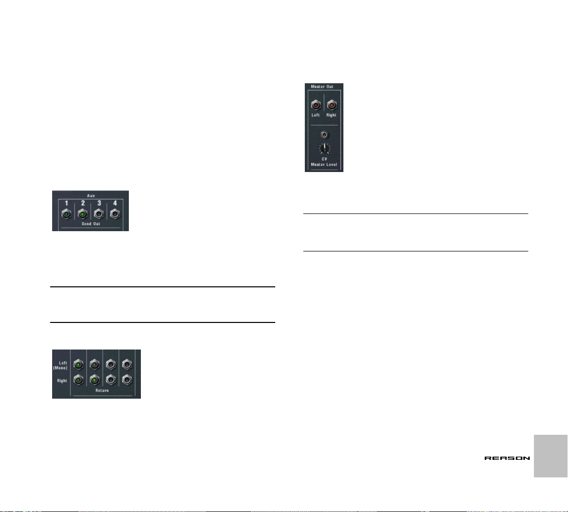
Connections
All input and output connectors are as usual located on the back panel of the
Mixer 14:2. Special connectors are used for “chaining” two or more Mixers
together. This is described on page 86.
Mixer Channel Connections
➜ Each mixer channel features stereo left/right inputs for connecting
audio devices.
Use the left input when manually connecting a mono signal source.
➜ In addition, there are two Control Voltage (CV) inputs (with associ-
ated voltage trim pots), for voltage controlling channel Level and
Pan from other devices.
➜ There are four stereo Return input connectors.
These are normally connected to the left and right outputs of effect devices.
Master Left/Right Outputs
Auxiliary (AUX) Send Out
➜ There are four mono Send Out connectors, which normally are used
to connect to the inputs of effect devices.
When a Send is connected to an effects device, the corresponding AUX
Send knob determines the level of the signal sent to the effect device for
each channel. The Send Output is taken post-channel fader.
! Note that some effects (for example the Comp-01 compressor or the
PEQ2 parametric EQ) are effect types which are not designed to be
used as AUX Send effects, but rather as insert effects, where the
whole signal is passed through the effect.
Auxiliary (AUX) Returns
➜ The Master outputs are auto-routed to the first available input pair
on the Audio Hardware interface.
This in turn sends the audio to the outputs of your audio hardware.
✪ Note that the Master outputs don’t have to be routed directly to the
Audio Hardware Interface. You could for example route the Master
outputs to an effect, and then route the effect outputs to the Hardware Interface instead.
➜ In addition, there is a Control Voltage (CV) input (and an associated
trim pot), for voltage controlling the Master Level from another device.
THE MIXER
85
Page 88

Chaining Mixers
Two chained Mixers are connected like this, the top Mixer being the “Master” Mixer.
If you need more Mixer channels, you can simply create a new Mixer. If you
do this, the Mixers are automatically connected via the “Chaining Master”
and “Chaining Aux” connectors.
➜ The newly created Mixer’s Master Output is connected to the origi-
nal Mixer’s Chaining Master input.
The Master Out Level for the new Mixer is now controllable from the original Mixer’s Master fader - so that this fader now controls the Master output level of both mixers.
➜ The newly created Mixer’s four Aux Send outputs is connected to
the original Mixer’s Chaining Aux connectors.
The new Mixer will now have access to any Aux Send effects connected
to the original Mixer, via the same corresponding Aux Send(s).
This way, the two Mixers operate as “one”.
! One exception is the Mute/Solo function, which is not chained.
Thus, soloing a channel in one of the Mixers, will not mute the channels in the other Mixer.
You can create as many Mixers as you like, they will be chained in the same
way, with one Mixer remaining the “master” (i.e. it controls the Master level of
all chained Mixers and supplies the Aux Send effect sources).
Partially or Non-Chained Mixers
You can also have several Mixers that are only partially or not chained at all.
➜ You may for example wish to have different Aux Send effects for
one Mixer.
Then simply disconnect one or more of the Send Out to Chaining Aux
connectors, and assign new Send effects.
➜ You could for example send the Master output of one Mixer to an-
other Input pair on the Audio In Hardware interface, instead of the
Chaining Master inputs.
86
THE MIXER
Page 89

REDRUM
11
Page 90
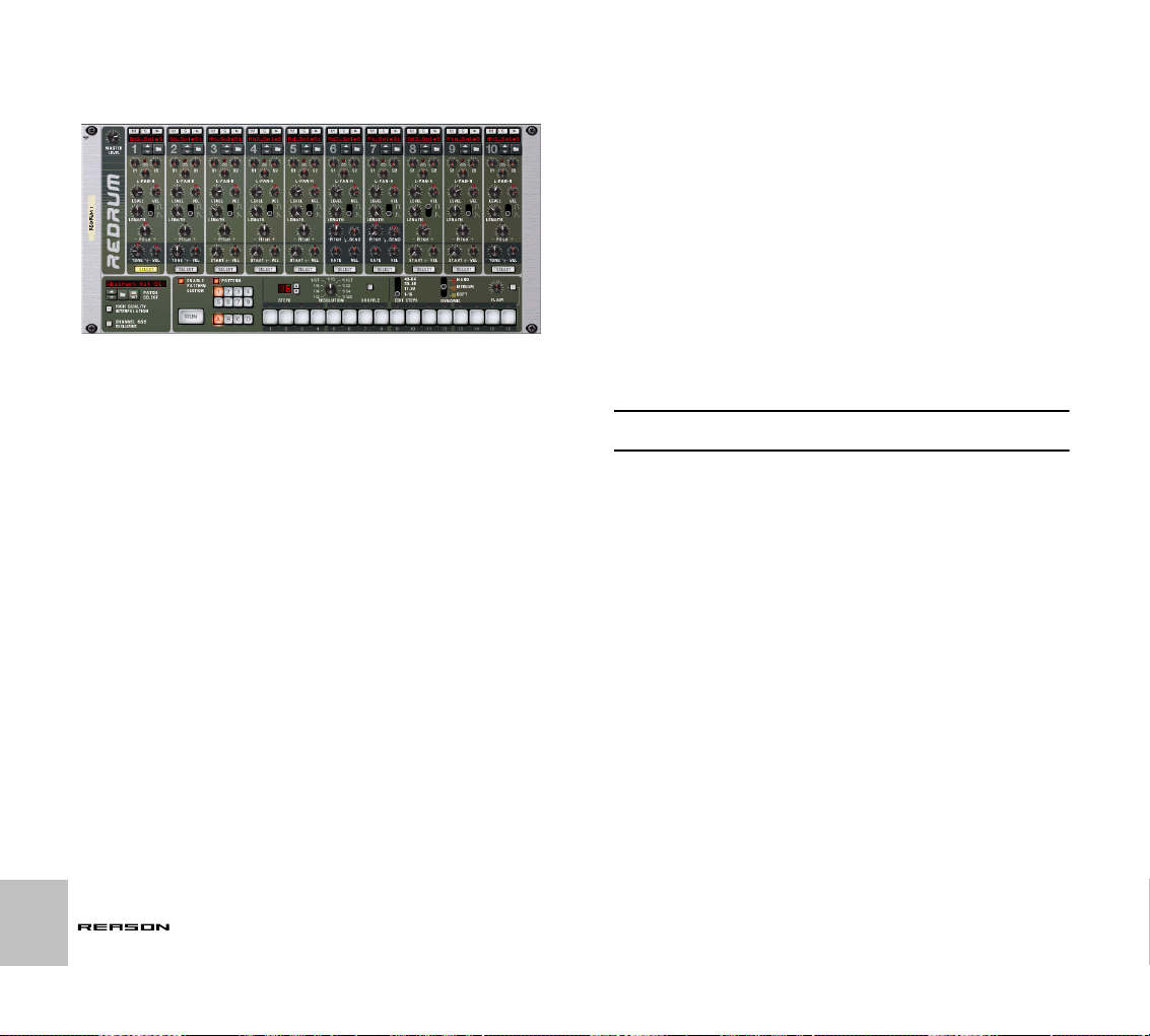
Introduction
At first glance, Redrum looks styled after pattern-based drum machines, like
the legendary Roland 808/909 units. Indeed, it does have a row of 16 step
buttons that are used for step programming patterns, just like the aforementioned classics. There are significant differences, however. Redrum features
ten drum “channels” that can each be loaded with an audio file, allowing for
completely open-ended sound possibilities. Don’t like the snare - just change
it. Complete drumkits can be saved as Redrum Patches, allowing you to mix
and match drum sounds and make up custom kits with ease.
About File Formats
Redrum reads two basic types of files:
Redrum Patches
A Redrum patch (Windows extension “.drp”) contains all settings for all ten
drum sound channels, including file references to the used drum samples
(but not the actual drum samples themselves). Switching patches is the
same as selecting a new drum kit.
Drum Samples
Redrum can read and play back sample files of the following formats:
• Wave (.wav) or AIFF (.aif)
• Any bit depth
• Any sample rate
• Stereo or Mono
! All samples are stored internally in 16-bit format, regardless of their
original bit depth or sample rate.
Wave and AIFF are the standard audio file formats for the PC and Mac platforms, respectively. Any audio or sample editor, regardless of platform, can
read and create audio files in at least one of these formats, and some of
them in both formats.
88
REDRUM
Page 91

Using Patches
When you create a new Redrum device it is empty. Before it can play back
any audio you must first load a Redrum patch (or create one from scratch, by
loading individual drum samples). A Redrum patch contains settings for the
ten drum sound channels, complete with file references to the drum samples
used.
! Redrum patterns are not part of the patch!
Loading a Patch
To load a patch, use one of the following methods:
➜ Use the browser to locate and open the desired patch.
To open the browser, select “Browse Redrum Patches” from the Edit
menu or device context menu, or click the folder button in the patch section on the device panel.
➜ Once you have selected a patch, you can step between all the
patches in the same folder by using the arrow buttons next to the
patch name display.
➜ If you click on the patch name display on the device panel, a pop-up
menu will appear, listing all patches in the current folder.
This allows you to quickly select another patch in the same folder, without
having to step through each one in turn.
Checking the Sounds in a Patch
There are two ways you can listen to the sounds in a patch without programming a pattern:
➜ By clicking the Trigger (arrow) button at the top of each drum sound
channel.
➜ By playing the keys C1 to A1 on your MIDI keyboard.
C1 plays drum sound channel 1 and so on. See also page 96.
Both these methods play back the drum sample for the corresponding drum
sound channel, with all settings for the sound applied.
Creating a new Patch
To create a patch of your own (or modify an existing patch), you use the following basic steps:
1. Click the folder button for a drum sound channel.
The Redrum sample browser opens.
2. Locate and open a drum sample.
You will find a large number of drum samples in the Factory Sound Bank
(in the folder Redrum Drum Kits/xclusive drums-sorted). You can also
use any AIFF or Wave file for this.
3. Make the desired settings for the drum sound channel.
The parameters are described on page 93.
4. Repeat steps 1 and 3 for the other drum sound channels.
5. When you’re satisfied with the drum kit, you can save the patch by
clicking the Floppy Disk button in the patch section on the device
panel.
Note however, that you don’t necessarily need to save the patch - all settings are included when you save the song.
Creating an Empty Patch
To “initialize” the settings in the Redrum, select “Initialize Patch” from the Edit
menu or the device context menu. This removes all samples for all drum
sound channels, and sets all parameters to their default values.
REDRUM
89
Page 92

Programming Patterns
About Pattern Selection
As described in the Getting Started book, each pattern device (such as the
Redrum) has 32 pattern memories, divided into four banks. To select a pattern, click a Pattern button (or, if the desired pattern is in another bank, first
click the Bank button and then click the Pattern button).
➜ If you select a new pattern during playback, the change will take ef-
fect on the next downbeat (according to the time signature set in the
transport panel).
If you automate pattern changes in the main sequencer, you can make
them happen at any position - see page 25.
➜ Note that you cannot load or save patterns - they are only stored as
part of a song.
However, you can move patterns from one location to another (even between songs) by using the Cut, Copy and Paste Pattern commands. This
is explained in the chapter “Using Pattern Devices” in the Getting Started
book.
Pattern Programming Basics
If you are unfamiliar with step programming patterns, the basic principle is
very intuitive and easy to learn. Proceed as follows:
1. Load a Redrum patch, if one isn’t already loaded.
2. Make sure an empty pattern is selected.
If you like, use the Clear Pattern command on the Edit menu or device
context menu to make sure.
3. Make sure that the “Enable Pattern Section” and the “Pattern” buttons are activated (lit).
5. Select a Redrum channel, by clicking the “Select” button at the bottom of the channel.
The button lights up, indicating that this channel and the drum sound it
contains is selected.
6. While in Run mode, press Step button 1, so that it lights up.
The selected sound will now play every time Step 1 is “passed over”.
7. Clicking other Step buttons so they light up will play back the selected sound as the sequencer passes those steps.
Clicking on a selected (lit) step button a second time removes the sound
from that step and the button goes dark again. You can click and drag to
add or remove steps quickly.
8. Select another Redrum channel to program steps for that sound.
Selecting a new sound or channel also removes the visual indications
(static lit buttons) of step entries for the previously selected sound. The
step buttons always show step entries for the currently selected sound.
9. Continue switching between sounds, and programming steps to
build your pattern.
Note that you can erase or add step entries even if Run mode isn’t activated.
Setting Pattern Length
You may want to make settings for Pattern length, i.e the number of steps the
pattern should play before repeating:
90
4. Press the “Run” button.
There will be no sound, as no pattern steps have been recorded yet. But
as you can see, the LEDs over the Step button light up consecutively,
moving from left to right, and then starts over. Each Step button represents one “step” in the Pattern.
REDRUM
➜ Use the “Steps” spin controls to set the number of steps you wish
the pattern to play.
The range is 1 to 64. You can always extend the number of steps at a
later stage, as this will merely add empty steps at the end of the original
pattern. You could also make it shorter, but that would (obviously) mean
that the steps “outside” the new length won’t be heard. These steps
aren’t erased though; if you raise the Steps value again, the steps will be
played back again.
Page 93

About the “Edit Steps” Switch
If you set the pattern length to more than 16 steps, the pattern steps following after the 16th won’t be visible, although they will play back. To view and
be able to edit the next 16 steps, you have to set the Edit Steps switch to 17-
32. To see and edit steps beyond 32 you set the switch to 33-48, and so on.
Setting Pattern Resolution
Redrum always follows the tempo setting on the transport panel, but you can
also make Redrum play in different “resolutions” in relation to the tempo setting. Changing the Resolution setting changes the length of each step, and
thereby the “speed” of the pattern.
This is explained in the chapter “Using Pattern Devices” in the Getting
Started book.
Step Dynamics
When you enter step notes for a drum sound, you can set the velocity value
for each step to one of three values: Hard, Medium or Soft. This is done by
setting the Dynamic switch before entering the note.
➜ When you use different dynamics, the resulting difference in the
sound (loudness, pitch, etc.), is governed by the “VEL” knob settings for each drum channel (see page 93).
If no velocity amount is set for a drum channel, it will play back the same,
regardless of the Dynamic setting.
➜ To change the dynamics for an already programmed step, set the
switch to the dynamic value you wish to change it to and click on
the step.
! Note that if you are triggering Redrum via MIDI or from the main se-
quencer, the sounds will react to velocity like any other audio device. The Dynamic values are there to offer velocity control when
using the built-in pattern sequencer.
Pattern Shuffle
Shuffle is a rhythmic feature, that gives the music a more or less pronounced
swing feel. It works by delaying all sixteenth notes that fall in between the
eighth notes.
You can activate or deactivate shuffle individually for each Redrum pattern
by clicking the Shuffle button on the device panel.
However, the amount of shuffle is set globally with the Pattern Shuffle control
on the transport panel.
The color of the step buttons reflect the dynamics for each step. Soft notes are light
yellow, Medium notes are orange and Hard are red.
➜ When the Medium value is selected, you can enter Hard notes by
holding down [Shift] and clicking.
In the same way, you can enter Soft notes by holding down [Option]
(Mac) or [Alt] (Windows) and clicking. Note that this doesn’t change the
Dynamic setting on the device panel - it only affects the notes you enter.
REDRUM
91
Page 94

Flam
A flam is when you double-strike a drum, to create a rhythmic or dynamic effect. Applying flam to a step entry will add a second “hit” to a drum sound.
The flam amount knob determines the delay between the two hits.
To add a flam drum note, proceed as follows:
1. Activate flam by clicking the Flam button.
2. Click on a step to add a note (taking the Dynamic setting into account as usual).
A red LED is lit above the step to indicate that flam will be applied to that
step.
3. Use the Flam knob to set the desired amount of flam.
The flam amount is global for all patterns in the device.
➜ To add or remove flam to or from an existing step note, click directly
on the corresponding flam LED.
You can also click and drag on the LEDs to add or remove several flam
steps quickly.
➜ Applying flam to several consecutive step entries is a quick way to
produce drum rolls.
By adjusting the Flam knob you can create 1/32 notes even if the step
resolution is 1/16, for example.
The Pattern Enable switch
The Enable Pattern Section switch
If this is deactivated, Redrum will function as a pure “sound module”, i.e. the
internal Pattern sequencer is disengaged. Use this mode if you wish to control Redrum exclusively from the main sequencer or via MIDI (see page 96).
Pattern Functions
When a Redrum device is selected, you will find some specific pattern functions on the Edit menu (and on the device context menu):
Function
|
Shift Pattern Left/Right These functions move all notes in the pattern one
Shift Drum Left/Right The Shift Drum functions move all notes for the
Randomize Pattern Creates a random pattern. Random patterns can
Randomize Drum Creates a random pattern for the selected drum
Alter Pattern The Alter Pattern function modifies the selected
Alter Drum Works like the “Alter Pattern” function, but affects
Description
|
step to the left or right.
selected drum channel (the channel for which the
Select button is lit) one step to the left or right.
be great starting points and help you get new
ideas.
sound only - the notes for the other drum sound
channels are unaffected.
pattern by “shuffling” the current pattern notes
and redistributing them among the drum sounds
at random. This creates a less chaotic pattern
than the “Randomize Pattern” function.
Note that there must be something in the pattern
for the function to work on - using an Alter function on an empty pattern will not do anything.
the selected drum sound only.
92
If you deactivate the “Pattern” button, the pattern playback will be muted,
starting at the next downbeat (exactly as if you had selected an empty (silent)
pattern). For example, this can be used for bringing different pattern devices
in and out of the mix during playback.
REDRUM
Chaining Patterns
When you have created several patterns that belong together, you most
probably want to make these play back in a certain order. This is done by recording or inserting pattern changes into the main sequencer. See page 25.
Converting Pattern Data to Notes
You can convert Redrum Patterns to notes in the main sequencer. This allows you to edit the notes freely, create variations or use Groove quantizing.
This is described on page 10.
Page 95

Redrum Parameters
Drum Sound Settings
Redrum features ten drum sound channels that can each be loaded with a
Wave or AIFF sample. Although they are basically similar, there are three
“types” of drum sound channels, with slightly different features. This makes
some channels more suitable for certain types of drum sounds, but you are
of course free to configure your drum kits as you like.
On the following pages, all parameters will be listed. If a parameter is available for certain drum sound channels only, this will be stated.
Mute & Solo
At the top of each drum sound channel, you will find a Mute (M) and a Solo
(S) button. Muting a channel silences its output, while Soloing a channel
mutes all other channels. Several channels can be muted or soloed at the
same time.
You can also use keys on your MIDI keyboard to mute or solo individual
drum sounds in real time.
➜ The keys C2 to E3 (white keys only) will mute individual drum chan-
nels starting with channel 1.
The sounds are muted for as long as you hold the key(s) down.
➜ The keys C4 to E5 (white keys only) will solo individual drum chan-
nel, starting with channel 1.
The sounds are soloed for as long as you hold the key(s) down.
C2 C3 C4 C5
This is a great way to bring drum sounds in and out of the mix when playing
Reason live. You can also record the drum channel Mutes in the main sequencer, just like any other controller (see “Drawing and Editing Notes” on
page 20).
The Effect Sends (S1 & S2)
On the back panel of Redrum you will note two audio connections labeled
“Send Out” 1 and 2. When you create a Redrum device, these will by default
be auto-routed to the first two “Chaining Aux” inputs on the Mixer device (provided that these inputs aren’t already in use).
This feature allows you to add effects to independent drum sounds in the Redrum.
➜ Raising the S1 knob for a drum sound channel will send the sound
to the first send effect connected to the mixer.
Similarly, the S2 knob governs the send level to the second send effect in
the mixer.
➜ Note that there must be send effects connected to the AUX Sends
and Returns in the mixer for this to work.
➜ Another way to add independent effects to drum sounds is to use
the independent drum outputs.
See page 97.
Pan
12345678910 12345678910
Mute Solo
Sets the Pan (stereo position) for the channel.
➜ If the LED above the Pan control is lit, the drum sound uses a stereo
sample.
In that case, the Pan control serves as a stereo balance control.
REDRUM
93
Page 96

Level and Velocity
The Level knob sets the volume for the channel. However, the volume can
also be affected by velocity (as set with the Dynamic value, or as played via
MIDI). How much the volume should be affected by velocity is set with the
“Vel” knob.
➜ If the Vel knob is set to a positive value, the volume will become
louder with increasing velocity values.
The higher the Vel value, the larger the difference in volume between low
and high velocity values.
➜ A negative value inverts this relationship, so that the volume de-
creases with higher velocity values.
➜ If the Vel knob is set to zero (middle position), the sound will play at
a constant volume, regardless of the velocity.
When Vel is set to zero, the LED above the knob goes dark.
Length and the Decay/Gate switch
The Length knob determines the length of the drum sound, but the result depends on the setting of the Decay/Gate switch:
➜ In Decay mode (switch down), the sound will decay (gradually fade
out) after being triggered. The decay time is determined by the
Length setting.
In this mode, it doesn’t matter for how long a drum note is held (if played
back from the main sequencer or via MIDI) - the sound will play the same
length for short notes as for long notes. This is the traditional “drum machine” mode.
➜ In Gate mode (switch up), the sound will play for the set Length, and
then be cut off.
Furthermore, if a sound set to Gate mode is played from the main sequencer, from a CV/Gate device or via MIDI, the sound will be cut off
when the note ends or after the set Length, depending on which comes
first. Or in other words, the sound plays for as long as you hold the note,
but the Length setting serves as the maximum length for the sound.
There are several uses for the Gate mode:
• For “gated” drum sounds, when the tail of the sound is abruptly cut off
as an effect.
• For when you want to use very short sounds, and don’t want them to
“lose power” by being faded out.
• For when you play the Redrum from the sequencer or via MIDI, with
sounds for which the length is important (e.g. when using the Redrum
as a sound effects module).
! Audio samples sometimes contain a “loop”, which is set by editing
the audio in a sample editor. This loop repeats a part of the sample
to produce sustain as long as you hold down a note. Drum samples
usually don’t contain loops, but who is to say that Redrum should
only play drum samples?
Note that if a sample contains a loop, and Length is set to maximum, the sound will have infinite sustain, in other words it will
never become silent, even if you stop playback. Decreasing the
Length setting solves this problem.
Pitch
Sets the pitch of the sound. The range is +/- 1 octave.
➜ When the pitch is set to any other value than 0, the LED above the
knob lights up to indicate that the sample isn’t played back at its
original pitch.
94
REDRUM
Page 97

Pitch Bend
By setting the Bend knob to a positive or negative value, you specify the start
pitch of the sound (relative to the Pitch setting). The pitch of the sound will
then be bent to the main Pitch value. Thus, selecting a positive Bend value
will cause the pitch to start higher and bend down to the original Pitch, and
vice versa.
➜ The Rate knob determines the bend time - the higher the value, the
slower the bend.
➜ The Vel knob determines how the Bend amount should be affected
by velocity.
With a positive Vel value, higher velocity results in wider pitch bends.
➜ The Bend and Vel knobs have LEDs that light up when the functions
are activated (i.e. when a value other than zero is selected).
! Pitch bend is available for drum sound channels 6 and 7 only.
Tone
The Tone knob determines the brightness of the drum sound. Raising this
parameter results in a brighter sound. The Vel knob determines whether the
sound should become brighter (positive Vel value) or darker (negative Vel
value) with higher velocity.
➜ The Tone and Vel knobs have LEDs that light up when the functions
are activated (i.e. when a value other than zero is selected).
! The Tone controls are available for drum sound channels 1, 2 and
10 only.
Sample Start
The Start parameter allows you to adjust the start point of the sample. The
higher the Start value, the further the start point is moved “into” the sample. If
you set the Start Velocity knob to a positive amount, the sample start point is
moved forward with higher velocities. A negative Start Velocity amount inverts this relationship.
➜ When Start Velocity is set to any other value than zero, the LED
above the knob lights up.
➜ A negative Start Velocity amount is only useful if you have set the
Start parameter to a value higher than 0.
By raising the Start value a bit and setting Start Velocity to a negative
value, you can create rather realistic velocity control over some drum
sounds. This is because the very first transients in the drum sound will
only be heard when you play hard notes.
! The Sample Start settings are available for drum sound channels 3-
5, 8 and 9.
Global Settings
Channel 8 & 9 Exclusive
If this button is activated, the sounds loaded into drum channels 8 and 9 will
be exclusive. In other words, if a sound is played in channel 8 it will be silenced the moment a sound is triggered in channel 9, and vice versa.
The most obvious application for this feature is to “cut off” an open hi-hat with
a closed hi-hat, just like a real one does.
REDRUM
95
Page 98

High Quality Interpolation
When this is activated, the sample playback is calculated using a more advanced interpolation algorithm. This results in better audio quality, especially
for drum samples with a lot of high frequency content.
➜ High Quality Interpolation uses more computer power - if you don’t
need it, it’s a good idea to turn it off!
Listen to the drum sounds in a context and determine whether you think
this setting makes any difference.
! If you are using a Macintosh with a G4 (Altivec) processor, turning
High Quality Interpolation off makes no difference.
Master Level
The Master Level knob in the top left corner of the device panel governs the
overall volume from Redrum.
Using Redrum as a Sound Module
The drum sounds in Redrum can be played via MIDI notes. Each drum
sound is triggered by a specific note number, starting at C1 (MIDI note num-
ber 36):
C1 C2
12345678910
This allows you to play Redrum live from a MIDI keyboard or a MIDI percussion controller, or to record or draw drum notes in the main sequencer. If you
like, you can combine pattern playback with additional drum notes, such as
fills and variations. However:
! If you want to use Redrum purely as a sound module (i.e. without
pattern playback) you should make sure that the “Enable Pattern
Section” button is deactivated.
Otherwise, the Redrum pattern sequencer will start as soon as you
start the main sequencer.
96
REDRUM
Page 99

Connections
On the back of the Redrum you will find the following connections:
For each drum sound channel:
Connection|Description
|
Audio Outputs There are individual audio outputs for each drum sound
Gate Out This sends out a gate signal when the drum sound is
Gate In Allows you to trigger the sound from another CV/Gate de-
Pitch CV In Lets you control the pitch of the drum sound from another
channel, allowing you to route a drum sound to a separate channel in the mixer, possibly via insert effects, etc.
For mono sounds, use the “Left (Mono)” output (and pan
the sound using the Pan control in the mixer).
When you use an individual output for a sound, the sound
is automatically excluded from the master stereo output.
played (from a pattern, via MIDI or by using the Trigger
button on the device panel). This lets you use the Redrum as a “trig sequencer”, controlling other devices.
The length of the gate signal depends on the Decay/Gate
setting for the sound: In Decay mode, a short “trig pulse”
is sent out, while in Gate mode, the gate signal will have
the same length as the drum note (see page 94).
vice. All settings apply, just as when playing the drum
sound conventionally.
CV device.
Others
Connection
|
Send Out 1-2 Outputs for the send signals controlled with the S1 and
Stereo Out This is the master stereo output, outputting a mix of all
Description
|
S2 knobs, as described on page 93.
drum sounds (except those for which you use individual
outputs).
REDRUM
97
Page 100
98
REDRUM
 Loading...