

Page 1
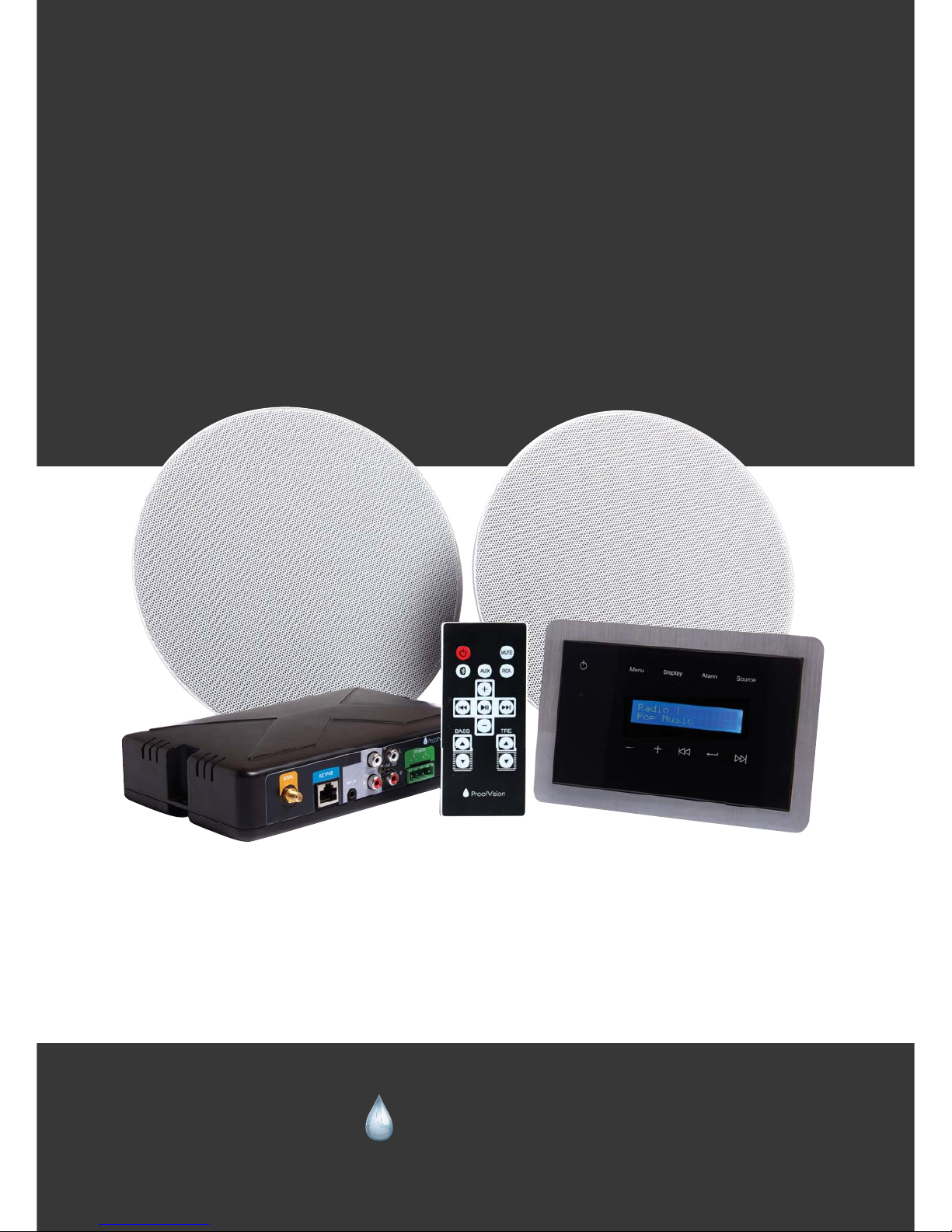
Model: PV48-BT
ProofVision Bluetooth
Bathroom Music System
Installation Manual
ProofVision
“Making it work in challenging conditions”
Page 2

Introduction
www.proofvision.co.uk 2
The Proofvision PV48-BT is an installed music system, which is easy to install in both your bathroom
and kitchen.
If you are not competent in general electrical installation and not confident in doing the installation
you should always seek professional assistance such as a qualified electrician.
With the Proofvision PV48-BT you are able to connect the set of speakers with the Proofvision bathroom TV and also switch from DAB radio, Bluetooth and AUX mode. You can change this using the
waterproof remote control or the waterproof touch panel.
Multi room can also be achieved by adding a set of ProofVision PV26-BT.
Control Panel
Cut out dimensions: 153mm x 100 x 40mm
Front screen dimensions: 168mm x 113mm
Inputs: Ethernet
IP Rating: IP64
HUB
Inputs: Ethernet, power supply, speaker cable, DAB/FM Antenna
Dimensions: 200mm x 125mm x 40mm
Speakers
Cut out dimensions: Diamieter: 227mm Depth:100mm
Overall dimensions: 252mm x 100mm
Inputs: Speaker cable
IP rating: IP44
Page 3
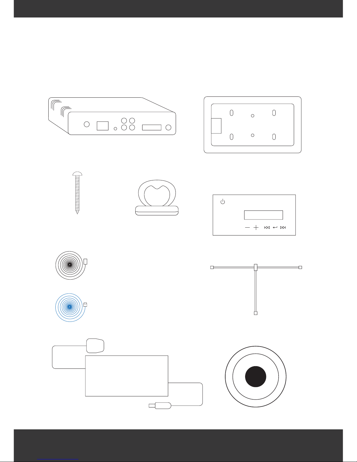
Pack contents
www.proofvision.co.uk 3
ProofVision
Menu Display Alarm Source
Hub
Face plate screws x 2 Suction pad
Speaker cable x 2
Cat5 ethernet cable x 1
DAB/FM antenna
Keypad
Power supply
Speaker x 2
Keypad mounting frame
Page 4
ProofVision
Instructions
www.proofvision.co.uk
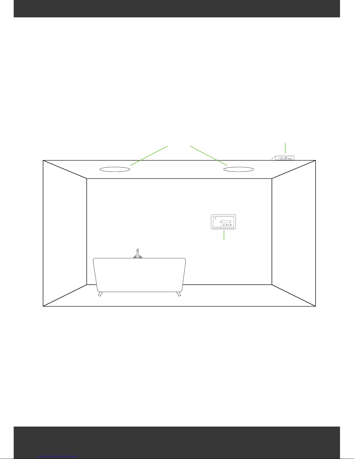
1. Locate a suitable position to install the keypad in your bathroom
2. You will also need to choose where to mount the ceiling speakers in your ceiling
3. The hub box is used to connect the keypad and speakers together as well as
connecting the system to mains power and the antenna. You will need to locate a
suitable place for the hub in your bathroom, ideally this should be located in the
ceiling of your room or in a cupboard.
For an optimum installation, cables should run through the walls to connect the hub,
speakers, keypad, power and antenna.
4
Menu Display Alarm Source
Speakers
Keypad
Hub
Page 5
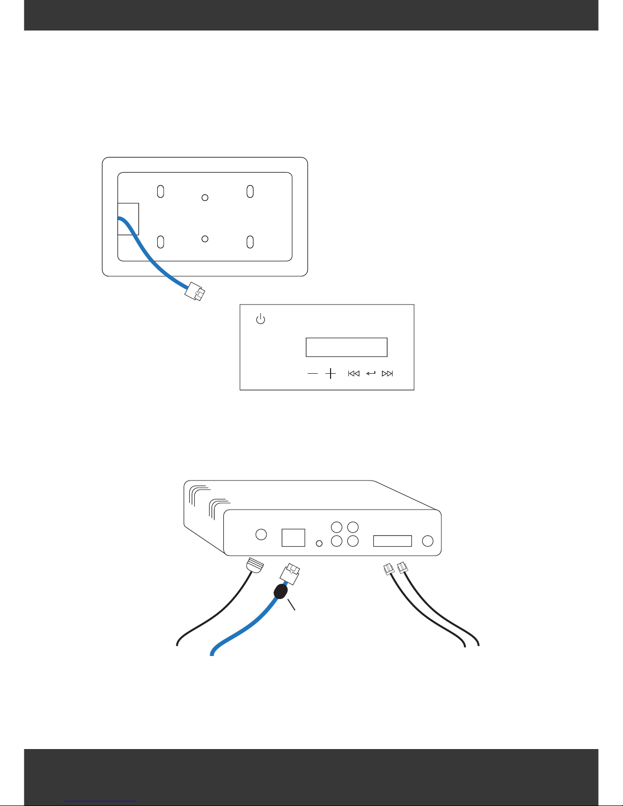
4. To mount the keypad you will need to create a recess in your wall large enough to
accommodate the mounting frame. Once you have done this then use the available
screw holes to attached the frame to the wall.
5. Connect the ethernet cable into the keypad then push the keypad into the frame
6. Connect the antenna, ethernet cable and speaker cables to the hub.
Ferret ring must be at the
hub end to prevent
interference
Note: It is important to note that the
blue ethernet cable will need to
come through the opening in the
frame as shown.
www.proofvision.co.uk 5
Menu Display Alarm Source
ProofVision
Antenna Ethernet Speakers
Page 6
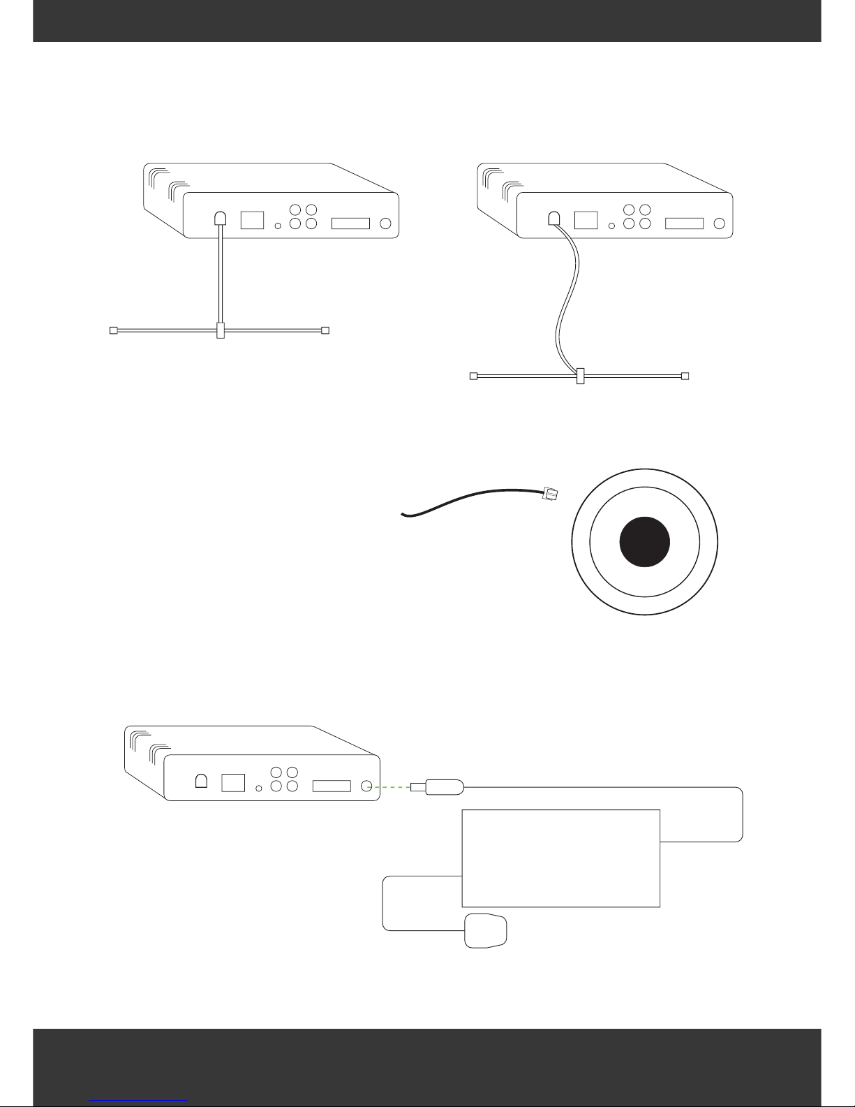
7. For optimal DAB/FM reception, ensure the antenna cable is not pulled tight
8. Connect speaker cables into the speakers
9. Connect power cable into the hub
www.proofvision.co.uk 6
ProofVision ProofVision
ProofVision
Page 7
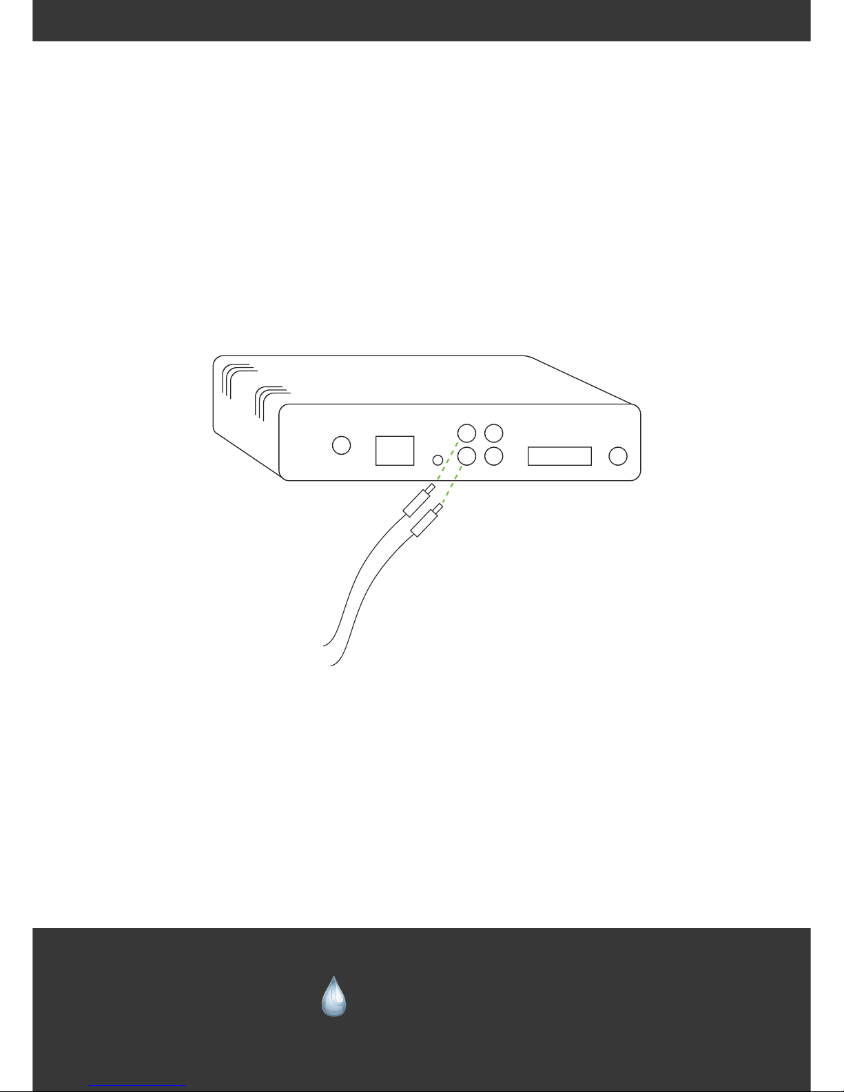
10. Refer to user manual for operating instructions
11. To connect a TV to the line input source, use the 3.5mm to RCA cable provided to
connect the TV audio out to the RCA input on the hub.
ProofVision
RCA IN
ProofVision
“Making it work in challenging conditions”
 Loading...