

Page 1
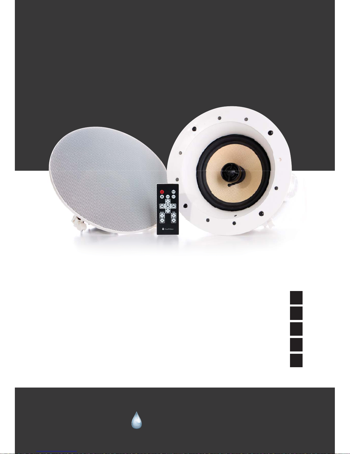
Model: PV26BT
Quick reference guide
1. Important safety instruction . . . . . . . . . . . . . . . . . . . . . . . . . . . . . . . . . . . . . . . . . . . . 2
2. Ceiling speakers / in-wall speakers . . . . . . . . . . . . . . . . . . . . . . . . . . . . . . . . . . . . . . 3
3. Operating instruction . . . . . . . . . . . . . . . . . . . . . . . . . . . . . . . . . . . . . . . . . . . . . . . . . 6
3. Remote Control. . . . . . . . . . . . . . . . . . . . . . . . . . . . . . . . . . . . . . . . . . . . . . . . . . . . . . 7
4. Bluetooth paring Method . . . . . . . . . . . . . . . . . . . . . . . . . . . . . . . . . . . . . . . . . . . . . 8
ProofVision Bluetooth
Bathroom Music System
User Manual
ProofVision
“Making it work in challenging conditions”
Page 2
Important safety instructions
www.proofvision.co.uk 2
Before installing the unit, please read and follow the instructions provided in the Installation Manual
included in this kit.
Before operating the unit, please read and follow the instructions provided in this User Manual
thoroughly and save it for future reference.
WARNING - To reduce the risk of fire or electric shock :install in
accordance with the manufacturer’s instructions
• do not attempt to disassemble this unit
• do not block any ventilation openings
• do not install near any heat sources such as radiators, stoves or other equipment that produce heat.
You are cautioned that any changes or modifications not expressly mentioned in this manual could
affect the normal operation of this equipment.
This product has been designed and tested to provide reasonable protection against harmful
interference in residential installation. However there is no guarantee that interference will not affect
in a particular installation. In these cases,
reorient the receiving antenna, try to increase the separation between the equipment and the
source of interference and/or connect the equipment into an outlet on a circuit different from that to
which the source of interference is
connected.
The entire risk of the installation, use, results and performance are borne by you.
When a socket plug, or a device connector is used as a mechanism to disconnect from the electrical
mains, the mechanism must be easily accessible at all times. Protect the power cord from being
walked on or pinched particularly
at plugs and the point where they exit from the apparatus.
Only use attachments/accessories specified by the manufacturer.
Use a certified technician for installation, repair and/or maintenance of this equipment and comply
with all the regulations in force in each country. Servicing maybe required when the apparatus has
been damaged in any way,
such as power-supply cord or plug is damaged, liquid has been spilled or objects have fallen into the
apparatus, the
apparatus has been exposed to water dripping or splashing, does not operate normally, or has been
dropped.
To change the batteries remove the cover by pressing on the tab while lifting the cover.
Use batteries type. AA1,5V. Do not discard used batteries with household waste.
gp
e in residential installation. However there is n
o
lar installation. In these cases,
receiving antenna, try to increase the separ
a
nterference and/or connect the equipment in
Page 3
Ceiling speakers/in-wall speakers installation
www.proofvision.co.uk
Getting the best performance from your ceiling speakers and In-wall speakers
The following information is a short guide to Installing ceiling and In-wall speakers. Reading through
the information before attempting speaker installation will ensure you get the best performance from
your in-wall and ceiling speakers
Precaution
Turn off all system power before connecting speakers.
Always wear protective eye wear when using tools.
Wear gloves when working with fibreglass loft insulation.
Necessary Installation Tools
• Drill
• Drill Bit ¼’ ~ ½’
• Stiff Wire (coat hanger or fish tape)
• 1’ Flat Bit (use if drilling through studs)
• Gloves
• Phillips Screwdriver
• Wire Strippers
• Plasterboard Saw
• Pencil
Step 1 – Choose Speaker Placement:
All applications apply for Ceiling and In-Wall speaker installation. The In-Wall and Ceiling speakers may
be used in new or existing ceiling or wall installations to reproduce stereo music or home cinema
surround sound.
Placing Speakers for Stereo Sound
In-Ceiling and In-Wall speakers have a uniform
(hemispherical) dispersion and do not require
special orientation for good sound. For stereo music
listening, place the speakers in the ceiling or wall, to
the left and right.
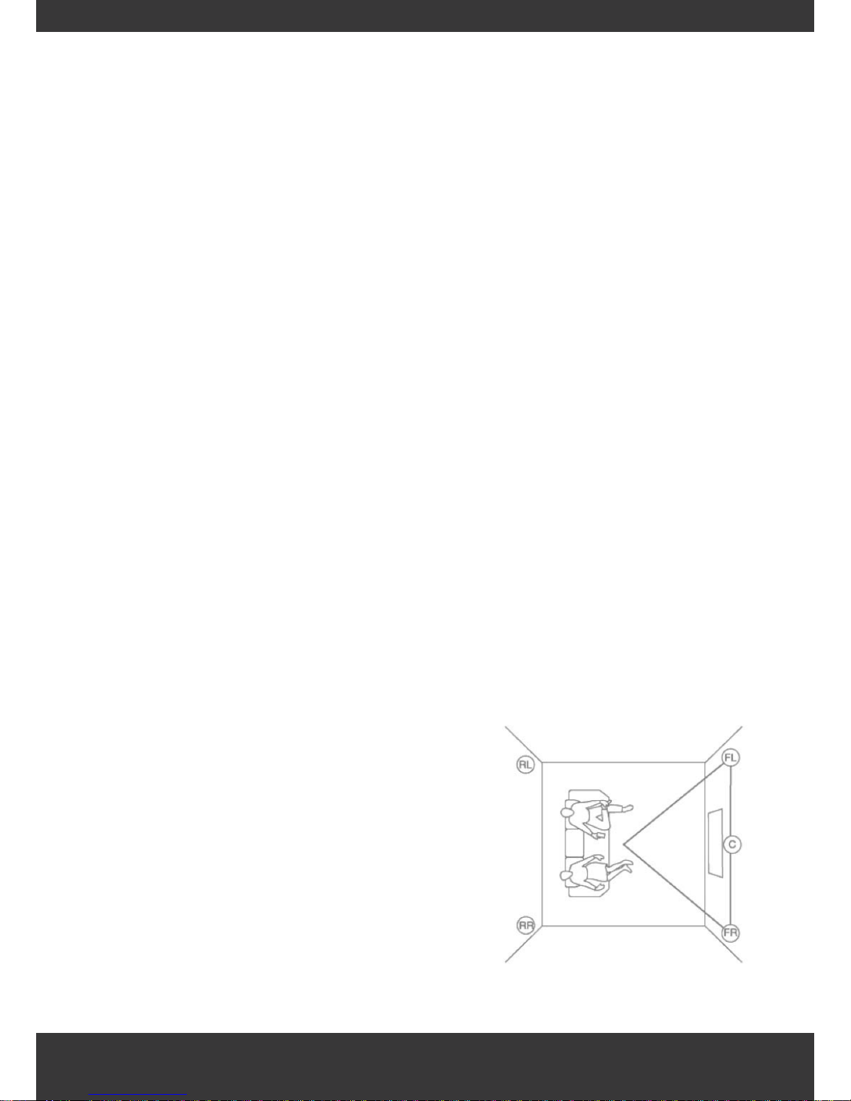
Think of your listening area as one tip of a triangle
with each leg of the triangle being equal. See
speakers FL (front left) and FR (front right) in Figure 1
below. Place the speakers as close as possible to the
two points they represent on the triangle.
Figure 1.
3
Page 4

Ceiling speakers/in-wall speakers installation
www.proofvision.co.uk
Placing Speakers for Surround Sound
For surround sound the minimum amount of speakers used will be five. Three at the front, FL (front left
channel) FR (front right channel) and C (centre channel) and two at the back, RL (rear left) and RR
(rear right). The front three speakers need to be on a level plane as possible with your ears whilst in your
seating position. This can either be achieved using in-wall speakers or the purpose built surround sound
ceiling speakers which have angled drive units that point directly down to your listening position. The
two rear speakers need to be placed left and right and directly behind your seating position, see Figure
1 on previous page.
Designing For Even Sound Distribution
When designing ceiling speaker systems in a multi-room environment, an important goal is uniform
sound coverage throughout the home. The goal should be to distribute the sound evenly in a way that
will not interfere with conversation and general day to day activities. In rooms where listening to music
isn't a primary objective (i.e back ground music) it is best to place the speakers around the perimeter of
room. It is especially important not to mount speakers above dinning tables or seating areas so that
people are not sitting directly under a speaker.
In locations where the primary objective is to listen to music the speakers can be placed evenly left and
right of the rooms main seating position as mentioned above.
If you need further help with the placement of your ceiling speakers please call or email us.
Step 2 - Check For Obstructions:
If an obstruction is found behind the plasterboard in the proposed location, you will need to choose a
different location for the speaker. Before installing In-Wall or Ceiling speakers in pre-existing plasterboard, check for joists or any other obstructions, such as metal pipes, which are hidden from your view.
Stud Locator:
The easiest, most efficient way to detect obstructions behind plasterboard is to use a stud finder. At
each proposed speaker location, use the stud locator to find an open space. Try to centre each
speaker between the joists. Slide the stud locator horizontally and vertically across the ceiling or walls to
locate the joists or any other obstructions.
Step 3 – Cut Speaker Openings:
1. At each speaker location, use the cardboard template to trace a cut line onto the ceiling or wall.
The Dimensions for the speaker, 229 x 229 x 145mm
2. At each location, drill a small hole in the plasterboard at the centre of the outline.
3. Bend a piece of stiff wire (e.g. coat hanger) about 6 inches from the end at a 90 – degree angle.
Insert the bent end into the hole and rotate the wire to check for any obstructions. If you hit anything,
patch the hole with plasterboard filler and choose a different installation location.
4. Using a fine – Plasterboard saw, carefully cut out each opening.
5. When finished cutting, remove plasterboard scrap from hole.
of
and
4
Page 5

Ceiling speakers/in-wall speakers installation
www.proofvision.co.uk
Step 4 – Connecting Speakers:
1. Strip the speaker wire with a pair of wire strippers.
2. Carefully strip off 50mm of the outer jacket. This will reveal the conductor contained inside – two
conductors for 2 conductor wire; four conductors for 4 conductor wires.
3. Conductors are protected by a plastic, colour-coded insulation jacket that must also be stripped.
Carefully strip 15mm of insulation off the conductors that you need. This will expose the copper wire
contained within. You are now ready to connect the wire to your speaker.
4. When connecting wires, observe the proper polarity of your amplifier (+) to (+) Red conductor (-) to
(-) Black conductor also make sure that the left channel of the amplifier is connected to the left
speaker, and the right channel is connected to the right speaker. For surround Sound, connect the
speaker to the appropriate channel on the amplifier or receiver.
5. Now connect the (-) and (+) conductors cables to the corresponding (-) and (+) speaker terminals.
Gently pull on the wire to verify a secure connection.
Step 5 – Installing the Speakers:
1. The easy and fast clamp installation procedure found on all the speakers that we supply, allows you
to simply clamp your speaker in place. Remove the grill by gently pushing one of clamp legs
toward the front of the speaker. They should lie in the full clockwise position so that all clamps lay
within the speaker cut-out.
2. Insert the speaker into the cut hole bringing the outer edge flush with the ceiling/wall. Use a Philips
screwdriver to tighten the four screw heads located around the front edge of the speaker. This will
automatically rotate the clamps behind the plasterboard and securely grip your speaker flange to
the ceiling/wall.
3. When you notice resistance in the tightening of all four screws the speaker has been successfully
sandwiched between the plasterboard and the speaker flange. The clamps provide a tight fit and
prevent unwanted vibration.
4. The screws should not be tightened so far that the flange bows, this will make the grill hard to fit. If
this occurs, back off the tension on the screws a little.
5. Gently push the speaker grill into the speaker baffle.
Painting The Speakers - Optional
If you plan on painting your speakers we advise you not to as it is not included in the manufacture
warranty. If deciding to paint the speakers we advise you to paint only the gills of the speakers as
they can detached, making sure you don't clog the holes which allow the sound to go through,
wait until the paint if fully dry before placing it back onto the speakers. Do not paint grills whilst it is
attached to the speakers.
ou
5
Page 6
Operating instructions
www.proofvision.co.uk 6
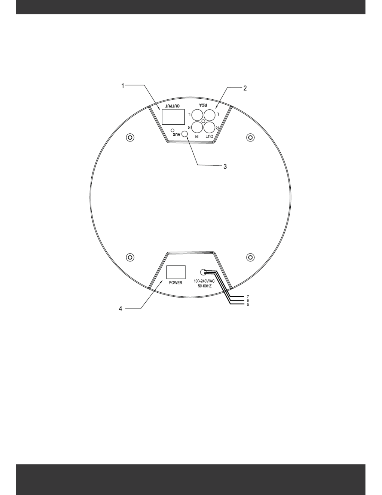
1 Main speaker output
2. RCA Input/output
3. AUX Input
4. Power Switch
5. Live wire: Black colour
6. Zero wire: White colour
7. Earth wire :Green colour
Connect AC power
Connect the AC power cable to the AC
(Live wire: Black colour, Zero wire: White colour, Earth wire :Green colour)
Connect Passive speaker cable
Connect speakers together
Page 7
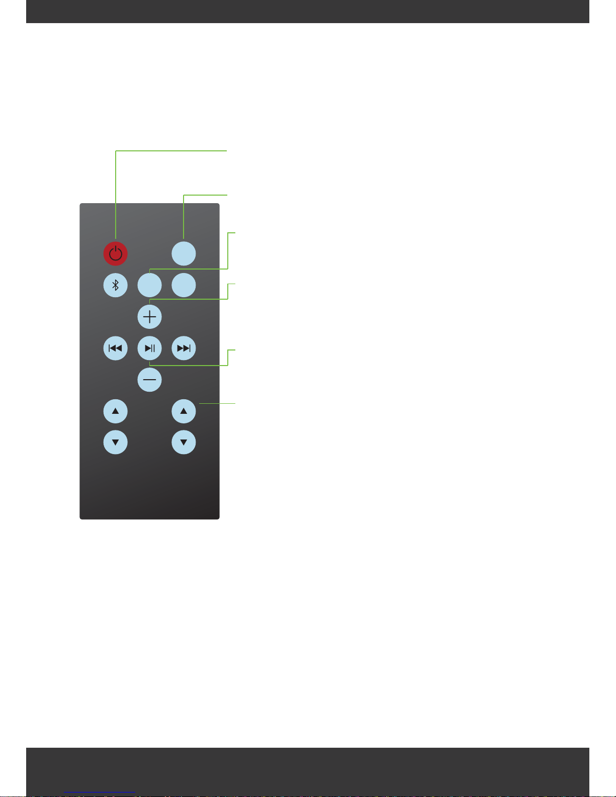
Remote control
www.proofvision.co.uk
1. ON/ OFF key:
This will turn the unit on and off.
2. Mute:
Press when you want to mute and un-mute
3. Mode Selection(Music Source Selection)
Press “Bluetooth/AUX/RCA” button on the remote control to select
music source
4. Increase/decrease in volume level:
Adjust the Volume level of the unit (+ = up )(- = down). Remote
control selection :Press 'VOL+’,increase the volume;press ‘VOL-’,
decrease the volume.
5. Play Pause Forward and Backwards:
Play or pause your music, Press ‘Play’,to play;Press ‘Play’ again, to
pause., switch back to previous music or skip forward.
6. Increase/ decrease in Bass and treble.
Use the + and - buttons to change settings .
Bass and Treble Adjusting
Press ‘Bass+’,‘Bass-’ to adjust bass.
Press ‘Treble+’,‘Treble-’ to adjust treble.
o
7
TREBLE
MUTE
RCAAUX
ProofVision
BASS
Page 8

Bluetooth pairing method
www.proofvision.co.uk
1. Automatic reconnection mode:press the “Bluetooth” button and enter it in to Bluetooth mode, once
done you will get a noise alert “one beep’ this will mean you devise is automatically detected. When
the Bluetooth device is successfully paired ,you will get another alert "with 2 beeps”.
2. Forced pairing mode: Press the "Bluetooth” button for 3 seconds,this will connect into the forced
pairing mode. you will know when the device is paired via Bluetooth when you get a noise alert with a
high pitched beep.
3. Open your Bluetooth on your device you will find this in your settings, Once you have turned the
Bluetooth on your device, your device will automatically start to search for Bluetooth device to pair with
the Bluetooth you will have to connect to the device named “ ProofVision’” .
4. Your Bluetooth device is successfully paired when you hear a noise alert “2 beeps rising” this is when
you are able to play your own music .
5. Bluetooth will be disconnected when you hear the noise alert. If Bluetooth is turned off or not in the
range of the Bluetooth working distance. you will hear 2 beeps descending.
8
Page 9

Specification
www.proofvision.co.uk
General
AC input 100-240V 1A
Power consumption 80 W
Size Φ238*140 mm
Net weight(approximately) 2.5kg
Operating temperature -5˚C ~55˚C (23˚F ~131˚F)
Operating humidity 5% ~ 95%
Input
AUX IN 700mV (3.5mm Stereo Jack)
RCA IN 700mV (RCA)
Amplifier
Power output 30W X 2ch (1kHz:8Ω)
T.H.D 1%
9
AC input 100-240V 1A
Si
ze
Φ
238*140 mm
Operating temperature -5˚C ~55˚C 23˚F ~131˚F
)
AUX IN 700mV (3.5mm Stereo Jack
)
Power output 30W X 2ch (1kHz8Ω
)
 Loading...