

Pronto MAGICARD 3649 - 0001, MAGICARD 3649 - 0002 Maintenance Manual
www.magicard.com
Colour ID Card Printer MAGICARD® Pronto Maintenance Manual
Magicard Pronto single sided colour ID Card Printer - 3649 - 0001
Magicard Pronto Mag single sided colour ID Card Printer - 3649 - 0002
Issue 1 22/01/09
Option
Standard
Standard
Standard

Ultra Electronics Ltd
Pronto Maintenance Manual
- 2 -
CONTENTS
Contents............................................................................................................................................................................. - 2 -
CONVENTIONS.....................................................................................................................................................................................................- 4 -
Warnings, Cautions and Notes. .................................................................................................................................................................................... - 4 -
SAFETY INSTRUCTIONS.................................................................................................................................................- 5 -
SECTION 1 INTRODUCTION TO THE PRINTING PROCESS...................................................................................- 6 -
section 1.1 card design limitations.......................................................................................................................................................................- 8 -
section 1.2 badge design.....................................................................................................................................................................................- 8 -
SECTION 2
KEY FEATURES OF THE MAGICARD PRONTO....................................................................................... - 9 -
section 2.1 specification of the magicard PRONTO........................................................................................................................................... - 10 -
SECTION 3 COMPONENT LAYOUT ............................................................................................................................- 11 -
SECTION 4 DYE FILM OPTIONS .................................................................................................................................- 14 -
Section 4.1 loading the dye film.......................................................................................................................................................................... - 15 -
Section 4.2 cards................................................................................................................................................................................................- 16 -
SECTION 5 PHILOSOPHY............................................................................................................................................- 18 -
section 5.1 repair and maintenance...................................................................................................................................................................- 18 -
SECTION 6 WARRANTY INFORMATION ....................................................................................................................- 19 -
section 6.1 The warranty.................................................................................................................................................................................... - 19 -
Section 6.2 Internet support...............................................................................................................................................................................- 20 -
section 6.3 recommended tools........................................................................................................................................................................ - 20 -
SECTION 7 CLEANING THE PRINTER........................................................................................................................ - 21 -
section 7.1 cleaning is important........................................................................................................................................................................ - 21 -
section 7.2 cleaning supplies.............................................................................................................................................................................- 21 -
section 7.3 cleaning the printer Rollers..............................................................................................................................................................- 22 -
section 7.4 replacing the cleaning roller............................................................................................................................................................. - 23 -
section 7.5 cleaning the Print Head. .................................................................................................................................................................. - 24 -
SECTION 8 MAGICARD PRONTO DRIVER................................................................................................................. - 25 -
section 8.1 installation instructions for Windows 2000/xp/2003 server & VISTA...............................................................................................- 25 -
section 8.1 installation instructions for Windows 2000/xp/2003 server & VISTA (continued…) .....................................................................- 26 -
section 8.2 un-installing the driver for windows 2000 / xp / 2003 server............................................................................................................ - 27 -
section 8.3 un-installing the driver for windows vista......................................................................................................................................... - 28 -
section 8.4 driver description ............................................................................................................................................................................. - 29 -
SECTION 9 PRINTER FUNCTIONS .............................................................................................................................- 30 -
section 9.1.1 printing a Test Card......................................................................................................................................................................... - 30 -
section 9.1.2 Printer cleaning mode...................................................................................................................................................................... - 30 -
section 9.2.1 soak test mode ................................................................................................................................................................................ - 31 -
SECTION 10 PRINT HEAD REPLACEMENT................................................................................................................. - 32 -
section 10.1 Print Head damage.........................................................................................................................................................................- 32 -
section 10.2 Print Head Electronic failure. ........................................................................................................................................................... - 33 -
section 10.3 replacing the Print Head. .................................................................................................................................................................- 33 -
section 10.3 replacing the Print Head (cont)........................................................................................................................................................ - 34 -
section 10.4 Setting the Print Head density calibration........................................................................................................................................- 35 -
Section 10.5 Print Head setup and adjustment .................................................................................................................................................... - 36 -
SECTION 11 DISMANTLING AND ASSEMBLING THE PRINTER................................................................................ - 37 -
section 11.1 removing & refitting the printer casing. ............................................................................................................................................ - 37 -
Section 11.2 Removing & Refitting the front fascia cover ....................................................................................................................................- 37 -
section 11.3 removal & refitting of the top dye-film sensor ..................................................................................................................................- 38 -
section 11.3 removing & Refitting of the lower dye-film sensor. ..........................................................................................................................- 38 -
section 11.5 removing & Refitting the controller pcb............................................................................................................................................- 39 -
section 11.6 removing & refitting of the front & rear card sensor......................................................................................................................... - 40 -
section 11.8 removal & refitting of left side components......................................................................................................................................- 41 -
section 11.9 removal and refitting of right side components................................................................................................................................ - 42 -
section 11.10 removal & refitting of the Drive motors & front card sensor.............................................................................................................- 43 -
Section 11.11 removal of the chassis cover...........................................................................................................................................................- 44 -
section 11.13 removal of the idle rollers.................................................................................................................................................................- 45 -
section 11.16 Removal and refitting of rollers........................................................................................................................................................- 46 -
section 11.17 removal & refitting of the card guide & middle card sensor.............................................................................................................- 46 -
SECTION 12 TROUBLESHOOTING...............................................................................................................................- 47 -
Section 12.1 initialisation sequence......................................................................................................................................................................- 47 -
Section 12.2 hardware problems..........................................................................................................................................................................- 48 -
Section 12.3 image problems............................................................................................................................................................................... - 49 -
Section 12.3 image problems COnt...................................................................................................................................................................... - 50 -

Ultra Electronics Ltd
Pronto Maintenance Manual
- 3 -
Section 12.4
printer driver problems..................................................................................................................................................................... - 51 -
Section 12.5 Magnetic encoding problems........................................................................................................................................................... - 52 -
SECTION 13 MAGICARD SUPPORT UTILITY...............................................................................................................- 53 -
SECTION 14 MAGNETIC ENCODING............................................................................................................................ - 58 -
section 14.1 magnetic encoding standards..........................................................................................................................................................- 58 -
SECTION 14.2 Basic Magnetic Encoding. ...............................................................................................................................................................- 60 -
SECTION 14.3 Encoding using Badge printing Software.........................................................................................................................................- 61 -
section 14.4 ASCII Character Set supported by the PRONTO............................................................................................................................ - 62 -
section 14.5 ISO standards..................................................................................................................................................................................- 62 -
section 14.6 error checking.................................................................................................................................................................................. - 63 -
SECTION 15 FITMENTS TO THE PRINTER..................................................................................................................- 64 -
SECTION 16 PARTS AND PART NUMBERS................................................................................................................. - 65 -
section 16.1 external components .......................................................................................................................................................................- 65 -
section 16.2 Top cover assembly (3633-0150).................................................................................................................................................... - 65 -
section 16.3 Print Head assembly (FG/3649-0160)............................................................................................................................................. - 66 -
section 16.5 Roller Layout .................................................................................................................................................................................... - 67 -
section 16.6 Drive mechanism right hand side. ...................................................................................................................................................- 68 -
section 16.7 Drive mechanism left hand side....................................................................................................................................................... - 69 -
section 16.8 Motor layout and part numbers........................................................................................................................................................- 70 -
section 16.9 Internal wiring & sensor part numbers............................................................................................................................................. - 71 -
section 16.10 Magnetic encoding option................................................................................................................................................................ - 72 -
SECTION 17 PRONTO SPARES LIST............................................................................................................................- 76 -
SECTION 18 FIRMWARE RELEASE HISTORY............................................................................................................. - 77 -
SECTION 19 PRONTO ERROR CODES........................................................................................................................ - 78 -

Ultra Electronics Ltd
Pronto Maintenance Manual
- 4 -
CONVENTIONS
WARNINGS, CAUTIONS AND NOTES.
Throughout this guide, the following conventions are used to identify important information.
WARNING Warning messages indicate where personal injury could result from not following the correct procedures.
CAUTION Caution messages indicate where damage to equipment could result from not following the correct
procedures.
NOTE Notes convey important information that is identified within the text.
The information contained in this document is subject to change without notice.
Ultra Electronics Limited shall not be liable for errors contained herein or for incidental consequential damages in
connection with the furnishing, performance or use of this material.
This document contains proprietary information belonging to Ultra Electronics Limited and may not be wholly or partially
copied, stored in a data retrieval system, disclosed to third parties or used for any purpose other than that for which it was
supplied, without the express written authority of Ultra Electronics Limited. All rights are reserved.
MAGICARD
®
, Rio, Tango, UltraCoverplus, Alto, Opera, Prima, Prima 2E, Prima 3, Holokote, Rio 2, Tango 2, Rio 2E,
Tango 2E, Enduro, Ultra Shield MAGICARD
®
is registered as a Trademark with the United States Patent and Trademark
Office, Reg. No. 2,197,276
The Ultra Secure feature of Magicard® Printers is protected by US PATENT No: 5,990,918 and by EUROPEAN PATENT
SPECIFICATION EP 0 817 726 B1.
Microsoft and Windows 2000, XP and Vista are trademarks of Microsoft Corporation.
Copyright © 2004 Ultra Electronics Limited.

Ultra Electronics Ltd
Pronto Maintenance Manual
- 5 -
SAFETY INSTRUCTIONS
Only use the Power Source supplied with the Printer by Magicard.
Do not to spill any liquid on the Printer.
Ensure that the Power Supply cable is not longer than 2 metres in length and includes a properly grounded conn ection.
If using this Printer in Germany :
To provide adequate short-circuit protection and over-current protection for this Printer, the building installation must be
protected by a 16 Amp Circuit Breaker.
Bei Anschluß des Druckers an die Stromversorgung muß sichergestellt werden, daß die Gebäudeinstallation mit einem
16 A-Überstromschalter abgesichert ist.
When Handling the Printer :
Avoid touching the thermal printing edge of the Print Head. Any grease and contamination will shorten the operational
life.
Before transporting the Printer, remove the Dye-Film and Card Hoppers and pack the Printer in it’s original packaging.
Location Requirements for your Printer :
A clean, dry level surface.
Adequate space for:
Cable access at the rear.
Allowance for air circulation.
An adequately ventilated room.
The correct Power Supply provided by Magicard.
Ambient temperature +10 to +30 degrees Centigrade.
Relative Humidity 20/70% RH.
Protection from direct sunlight and chemicals.
Protection from abrupt temperature changes.

Ultra Electronics Ltd
Pronto Maintenance Manual
- 6 -
SECTION 1 INTRODUCTION TO THE PRINTING PROCESS.
Sublimation uses heating elements in a rigid ceramic Print Head to transfer colour into or onto the PVC plastic surface
from the Dye-Film ribbon. The colours Yellow, Magenta & Cyan are absorbed into the PVC and the Black (K) & Clear
Overcoat are heated onto the Card surface.
Dye Sublimation
Dye Sublimation, or Dye-Sub, is known for it’s high quality photographic output. Dye Sublimation is also known as “Dye
Diffusion” or “Thermal Transfer”.
Inside the Dye Sublimation Printer is a roll of transparent film that resembles sheets of Red, Blue, Yellow, and Black
coloured cellophane bonded together end to end. On one surface of this film are solid dyes corresponding to the four
basic colours used in printing : Cyan, Magenta, Yellow and Black. Between the solid dye and the film, is a layer of
release agent, which controls the amount of dye released at each temperature. The Print Head is heated up as it passes
over the Film, causing the Dye to vaporise and permeate the glossy surface of the PVC Card before returning to solid
form on cooling. This is sublimation.
The Clear Overcoat Layer
The Overcoat layer acts as a protective film against wear and fading and can also carry a secure image, which cannot be
photocopied – e.g. the Magicard “Holokote” security watermark.
Dye Sublimation / Inkjet Printing
There are two factors that contribute to the quality of Dye Sublimation Printers. The first is continuous tone, and the other
is un-dithered colour. In Dye Sublimation printing, colours are not laid down as individual dots, as is done in Inkjet
Printers.
The colour produced by a Dye-Sub Printer is the result of the mixing of pigments
to get the actual colour. This is in contrast to most other printing methods which
use a tight group of coloured dots which, when seen by the human eye from a
distance, appear to be a colour (a process known as “dithering”). Under
magnification, the dots are clearly different colours, and when seen close up with
the naked eye the picture appears grainy. Because only one colour needs to be
printed (instead of up to four), a Dye Sub can place more dots on a card. It can
take a 1200 dpi Printer to get the same resolution a 300 dpi Dye-Sub Printer is
capable of.
Another difference that helps is that because the colour sublimates on the card
instead of being laid down as little dots, the edges of each pixel are blurred.
This gives the impression of blending for a more natural appearance. Dots from
an inkjet Printer leave large white gaps in between pixels, giving the impression
of a grain.
Since longevity is something we all want from our prints, it’s also reassuring to
know that because dyes sublimate instead of just being painted onto it’s surface,
dye sublimation prints resist fading and are colourfast.
ID Card with Overcoat Layer used as a Security Watermark

Ultra Electronics Ltd
Pronto Maintenance Manual
- 7 -
Subtractive Colour
This section contains some background material on the colour process used in printing. The colours (Yellow, Magenta,
and Cyan) used in dye sublimation use a subtractive colour process. Subtractive colour starts with an obje ct (often a
substrate such as paper or plastic) that reflects light and uses colourants (such as pigments or dyes) to subtract portions
of the white light illuminating an object to produce other colours.
If an object reflects all the white light back to the viewer, it appears white. If an object absorbs (subtracts) all the light
illuminating it, no light is reflected back to the viewer, it appears black. It is the subtractive process that allows everyday
objects around us to show colour. Colour paintings, colour photography and all colour printing processes use the
subtractive process to reproduce colour. In these cases, the reflective substrate is canvas (paintings) or paper/plastic
(photographs, prints), which is usually white. Colour monitors, TV’s, projectors etc. use the additive process.
Subtractive colour process (YMC) Additive colour process (RGB)
In theory, overprinting all three colours produces black. In reality, a dark grey is produced, so black is used as a fourth
printing ink, hence the ‘K’ (for monochrome) in YMCK.
The K Resin layer allows very sharp defined black text, Barcodes etc. to be added.
Printing
Due to the ceramic Print Head being rigid the quality of the Card surface is extremely important if high quality images are
to be produced. Cards should be selected which are cut cleanly at the edges and have perfectly flat surfaces.
There are various Card manufacturers and several different types of PVC card. Each of these will accept colour in
differing amounts using the same Print Head temperature. This is due to the PVC being used and the manufacturing
process.
When printing a full colour Card, the Print Head will get progressively hotter as it works. This is compensated for in the
Printer firmware but it may affect how evenly some card designs print.
Dust and debris on the Card surface will cause small white blemishes to appear in the image, so keeping the Cards and
“Sticky” Roller clean is imperative.
The Printer creates the Card by placing layers of dye onto the Card in the following sequence :
Yellow: (Y)
Magenta: (M)
Cyan: (C)
Black: (K) or Resin Bl ack
Clear: (O) or Overcoat
The Overcoat layer acts as a protective film against wear and fading and can also carry a secure image, which cannot be
photocopied (Ultra Secure).
Colours appearing on the monitor will not always be exactly the same as those printed by a Printer; this can be due to
various issues such as in transmitted light from the monitor colours can look different than viewing reflected light from the
Card. All monitors will show the same image slightly differently. Different plastic surfaces will give differing results and
the Dye-Film could vary slightly from batch to batch. For these reasons, the Printer Driver has been designed to allow the
user to adjust various aspects of the colour output.

Ultra Electronics Ltd
Pronto Maintenance Manual
- 8 -
SECTION 1.1 CARD DESIGN LIMITATIONS
It is important to remember that no Printer of this type will give the same quality / quantity of output as can be achieved
with a mass production Offset Printer. These Printers use a completely different process, print the same image hundreds
of times on large sheets of material, punch the finished Card out of the sheet and cost 10 times as much to purchase.
As long as badge designs are created to suit the dye sublimation process and the type of Card being pri nted, the results
will look as good to the naked eye as the far more expensive machines and can be personalised from Card to Card.
SECTION 1.2 BADGE DESIGN
It is important to realise that it is better to design a badge that will print successfully than attempt to print to the limits of
this type of Printer and cause waste and frustration.
The main issues to be considered are as follows :
The heat in the Print Head accumulates faster if dark colours are printed. The darker the colour the more heat is used to
print the layers onto the Card.
The Printer will automatically reduce the Print Head temperature to stop the colours getting darker along the length of the
Card.
This is set up in the mid range of the print density and will be slightly different on dark or light colours. Plain colour areas
are the most likely to show any variation so it is better to use textured colours where possible. If a coloured band runs
along the Card and into a picture, it will affect the area of the picture where it has increased the Print Head temperature.
Pictures will sometimes print better either at the start or the end of the Card, depending on the layout. Always try
reversing the whole image to select the best result. When printing on electronic Cards, ensure that the design of the
badge allows for any unevenness in the surface due to the embedded chip or antenna, these can cause white or faded
patches to appear in the text or image.
Ensure that any captured image such as an ID photograph is lit correctly for colour and brightness and is properly focused
as the Printer cannot improve poor quality input. If you add a logo or bitmap to the design, ensure that the size of the
original does not cause distortion and pixelation if it has to be enlarged or reduced to fit into the design. It is more
important to ensure the colour of any picture element is correct when printed (even if the colour looks incorrect on the
screen).

Ultra Electronics Ltd
Pronto Maintenance Manual
- 9 -
SECTION 2 KEY FEATURES OF THE MAGICARD PRONTO
Flexible
Drop in Dye-Film loading with automatic detection and set up for Dye-Film type.
Simple no mess cleaning operation.
Full Bleed Edge-to-Edge printing as standard option.
Smart
Attractive, compact design.
Multicoloured front Panel Button giving a clear indication of status.
USB interface.
Microsoft Certified “Plug and Play” Driver make the Pronto easy to install and use.
Secure
Magicard Pronto features the patented “Holokote” watermark technology.
Holokote watermark is printed on the Card during the normal print cycle at no extra co st.
Four Holokote design patterns offered as standard with every Pronto.
Holopatch is available using special Card stock to produce a highly visible gold seal.
Optional ISO 7811 Magnetic Stripe Encoder.

Ultra Electronics Ltd
Pronto Maintenance Manual
- 10 -
SECTION 2.1 SPECIFICATION OF THE MAGICARD PRONTO
Printing Method : Direct to Card Dye Sublimation.
Feed Format : Hand Feed.
Resolution : 300 dots per inch (11.8 Dots per mm).
Colour Reproduction : 256 graduations for each colour.
Internal Memory Size : 8 MBytes.
Printing Time : Approximately 35 seconds per side (YMCKO).
Approximately 7 seconds for monochrome
Printer Interface : USB Rev 1.1 (USB 2.0 compatible).
Operating Environment : Temperature 15 – 30 degrees Centigrade
Humidity 20% - 70%
Storage Environment : Temperature 15 – 55 degrees Centigrade
Humidity 20% - 70%
Power Source : External Power Supply (auto-selecting).
Input Voltage : AC Input 100 – 240 V AC.
Input Current Consumption : 1.8 Amps.
Frequency : 50 – 60 Hz.
Output Voltage : 18 – 24 V DC.
Output Current Supply : 3.2 Amps.
Output Power Rating : 60 Watts (Max).
Weight : 4.4 Kilograms (10 lbs)
Dimensions : 270mm (L) x 215mm (W) x 233mm (H)
17.8” (L) x 8.1” (W) x 9.2” (H).
Dye-Film loading : Drop in Dye Film design.
Dye-Film Set-up : Automatically detects Dye Film.
Software : Supplied with Windows 2000, 2003 Server, XP, Vista (32 bit) and
Windows 7 (32 bit) Drivers.
Magstripe Encoder : Optional HICO/LOCO Magnetic Stripe Encoder to ISO 7811.
Card Size : CR80 - 85.6 x 54.0 mm (3.375” x 2.125”) and
CR79 - 83.9 x 51.0 mm (3.303” x 2.051”) sized Cards.
Card Thickness : 0.51 – 1.02mm (0.020” – 0.040”)
Card Types : PVC.
Holopatch Cards are available. They are used with the Holokote feature
to produce a highly visible “gold seal” on the Card.
Print Length : Full card 1016 pixels (85.6mm)
Print Width : Full card 642 pixels (54.5mm)
Safety : CE Certified, UL listing USA
EMC : EN 50 081-1 and EN 50 082-1 (Europe) FCC pt 15 curve A (USA)
& CSA 08.8 curve A (Canada)
Warranty : Two years limited warranty (North America and EU only)
Elsewhere 1 year limited warranty.
Ultra Electronics Ltd
Pronto Maintenance Manual
- 11 -
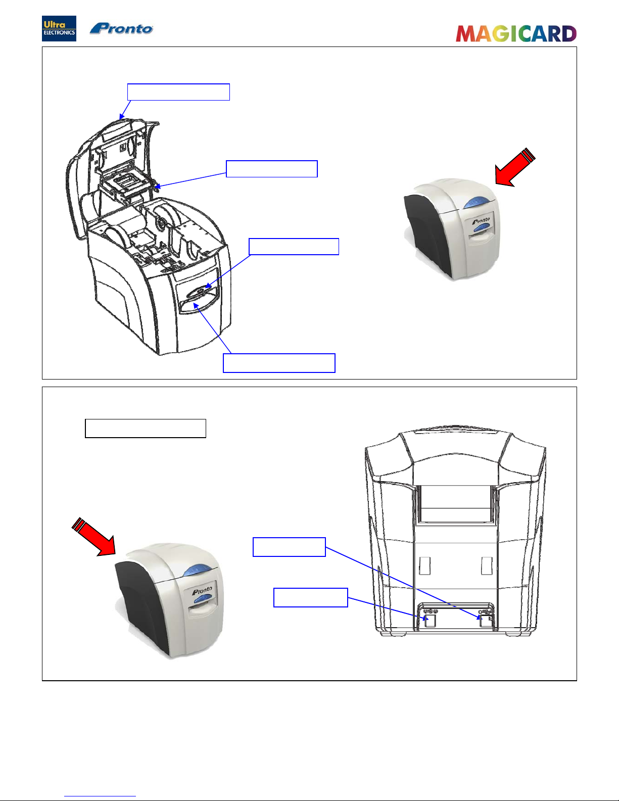
USB Socket
DC Power Input
SECTION 3 COMPONENT LAYOUT
Top Cover Opening Latch
Multicoloured Button
Hand Feed Entry / Exit Slot
Print Head Assembly
Printer Connections
Ultra Electronics Ltd
Pronto Maintenance Manual
- 12 -
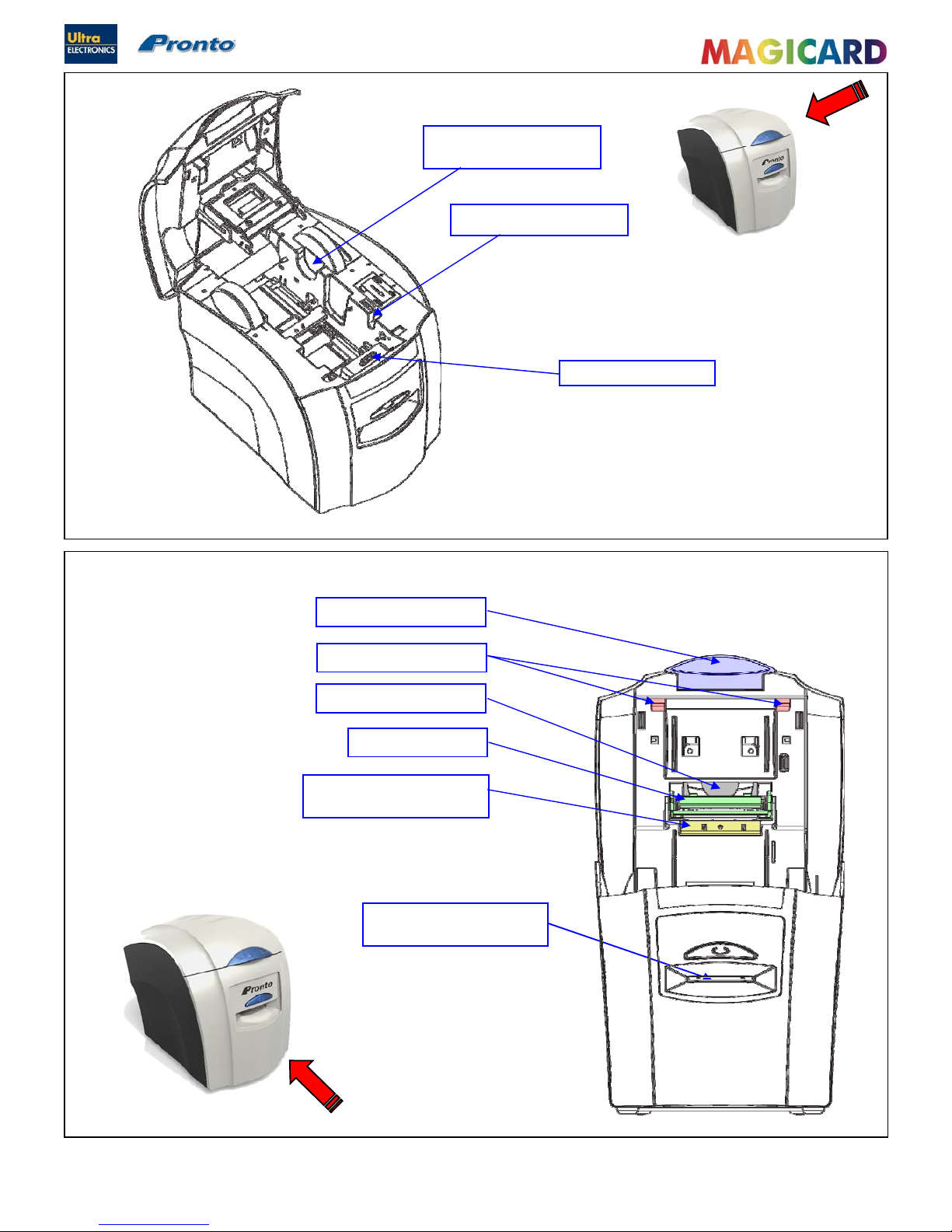
Print Head Assembly
Card Hand Feed Entry / Exit
Slot
Top Cover Opening Catch
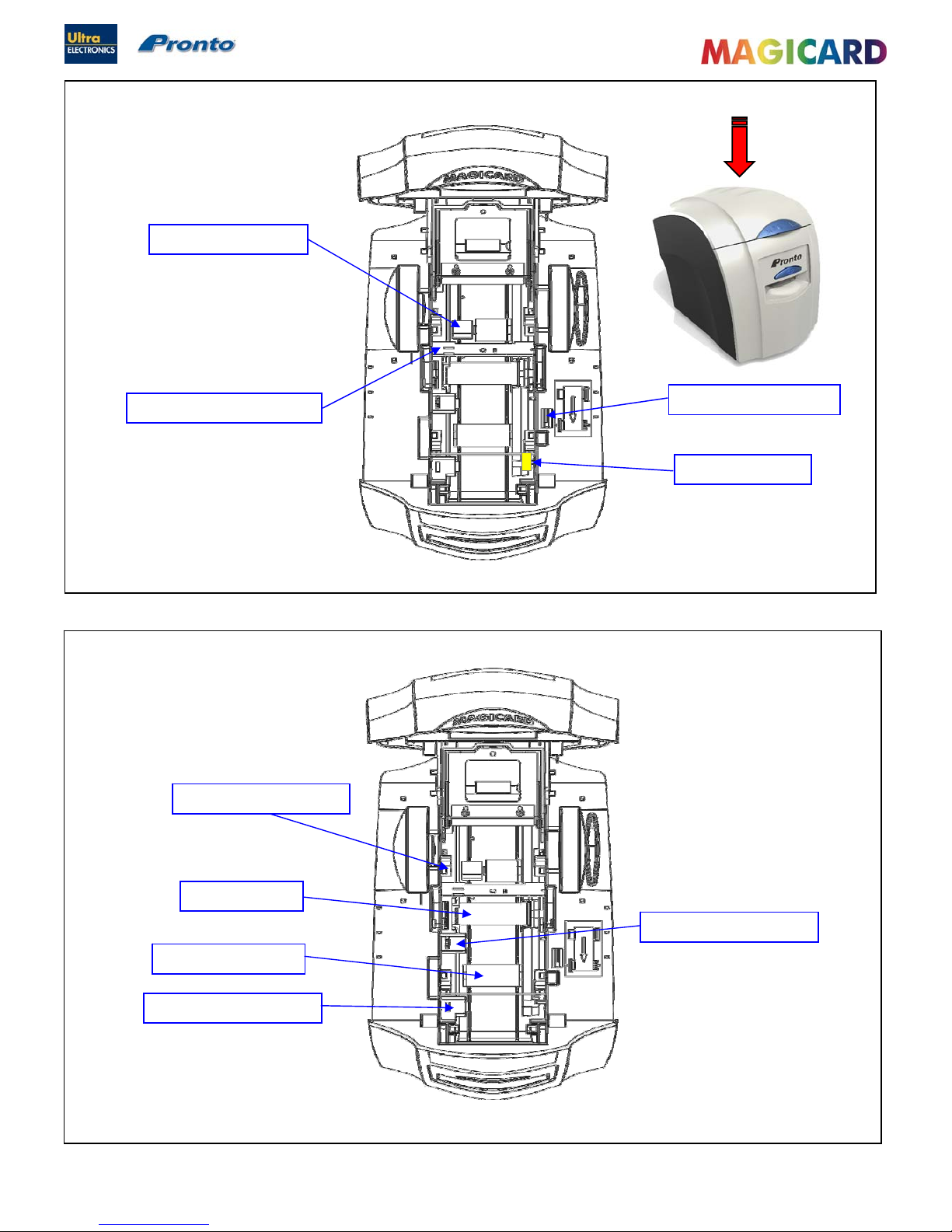
Top Cover Holding Latches
Print Head Cooling Fan
Dye Film Sensor Bracket
(upper)
Unused Dye Film Spool
Holder
Used Dye Film Spool Holder
Cleaning Roller Cassette
Ultra Electronics Ltd
Pronto Maintenance Manual
- 13 -
Top Cover Interlock Sensor
Magnetic Encoder Roller
Dye Film Sensor Bracket (lower)
Dye Film Drive Gear
Print Head Roller
Front Card Opto Sensor
Mid Card Opto Sensor
Rear Card Opto Sensor
Front Pinch Roller
Ultra Electronics Ltd
Pronto Maintenance Manual
- 14 -
SECTION 4 DYE FILM OPTIONS
MA300YMCKO Dye-Film is the appropriate choice for colour printing with the Pronto.
MA1000K & MA600KO Dye-Film – where cost is critical, monochrome printing is a fraction of the cost of colour printing.
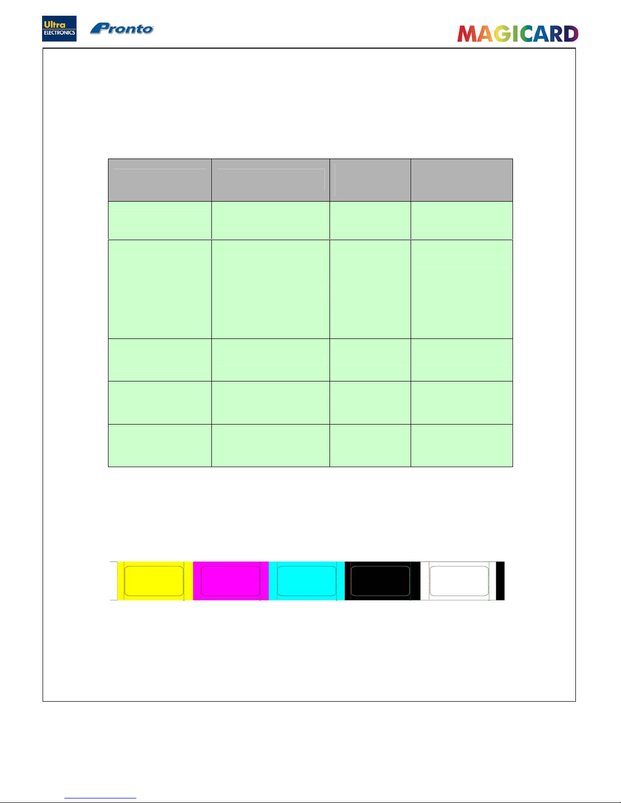
The Table below is a guide to selecting the best Dye-Film to use for any intended application.
Ribbon Layout Colour Key
Full color Cards
or monochrome
Cards per
Dye Film
Dye Film
Panel
layout
Part Number
Full
Colour
300 Cards YMCKO MA300YMCKO
Monochrome:
Black
Red
Blue
Green
Gold
Silver
White
Scratch
1000 Cards K
MA1000K n
(n = colour)
Black &
Overcoat
600 Cards KO MA600KO
Yellow (Y) Magenta (M) Cyan (C) Resin (K)
Overcoat (O)
Ultra Electronics Ltd
Pronto Maintenance Manual
- 15 -
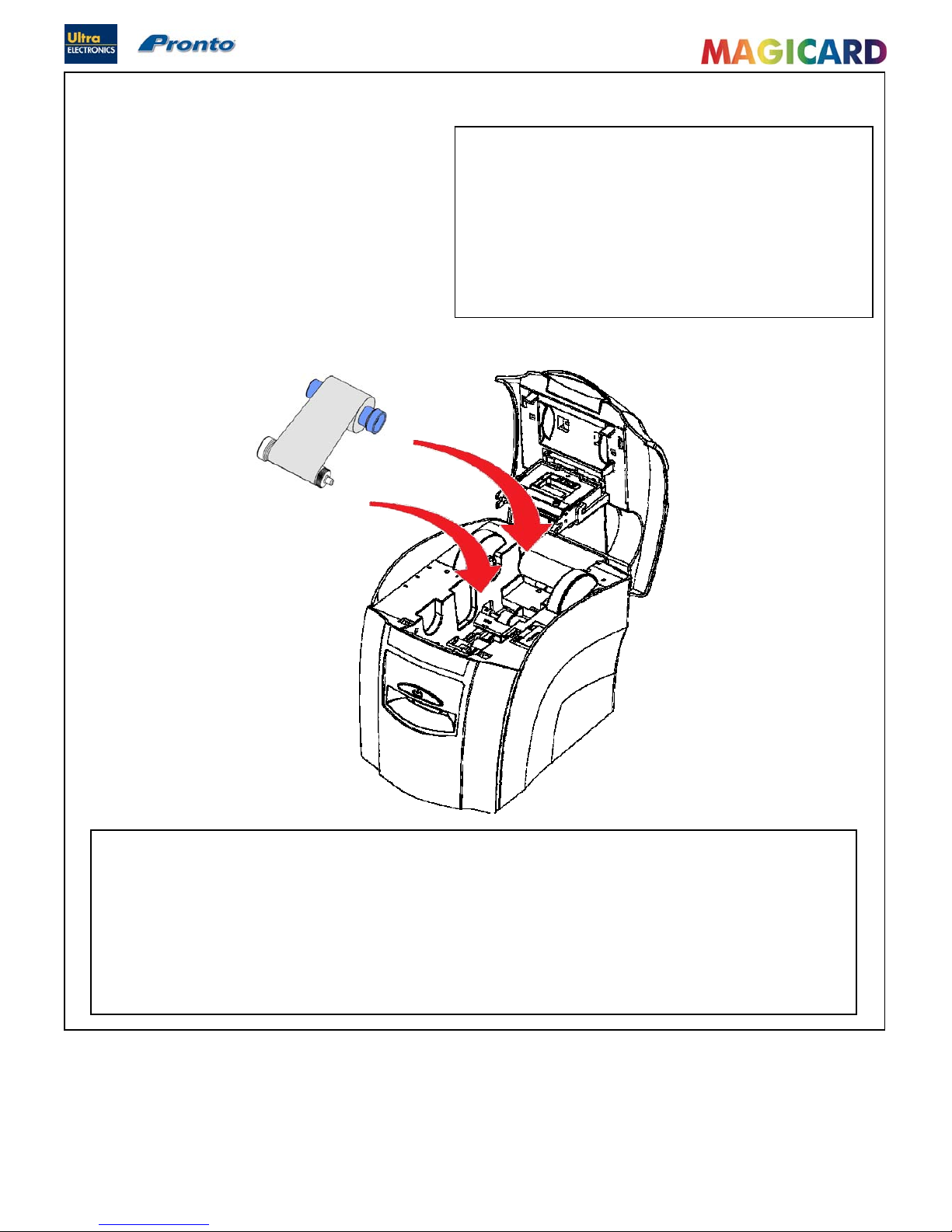
SECTION 4.1 LOADING THE DYE FILM.
Incorporated in colour, black and clear Dye-Film is an
electronic RFID protective Tag. When the Printer begins it’s
initialisation process, the Printer reads the Tag and looks for
the following information:
Dye-Film type.
Remaining number of prints.
If it fails to read any of the data from the RFID protective
Tag, the Printer assumes it has monochrome Dye-Film fitted.
Operate the top cover release Catch and lift the cover.
Place the two Spools into the front and rear cradles (left side first) and press it into place. Ensure the Gear
(front right) engages with the front Spool.
Gently close the top cover until it clicks into the closed position.
The Printer will automatically recognise the type of Film that has been loaded by reading the RFID Tag
when it initialises.
Ultra Electronics Ltd
Pronto Maintenance Manual
- 16 -
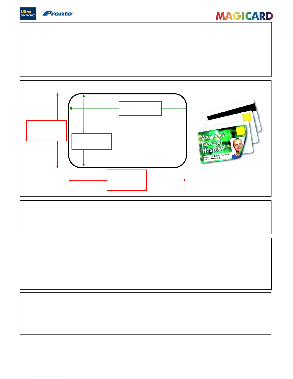
CR80
85.6mm or 3.375”
CR79
83.9mm or 3.303”
CR80
53.98mm or 2.125”
CR79
51mm or 2.051”
CR80 – 1016 Pixels
CR79 – 990 Pixels
CR80 – 642 Pixels
CR79 – 601 Pixels
Recommended
page size for
edge to edge
printing
ISO Standard Cards
Sizes
Printable Area of Cards
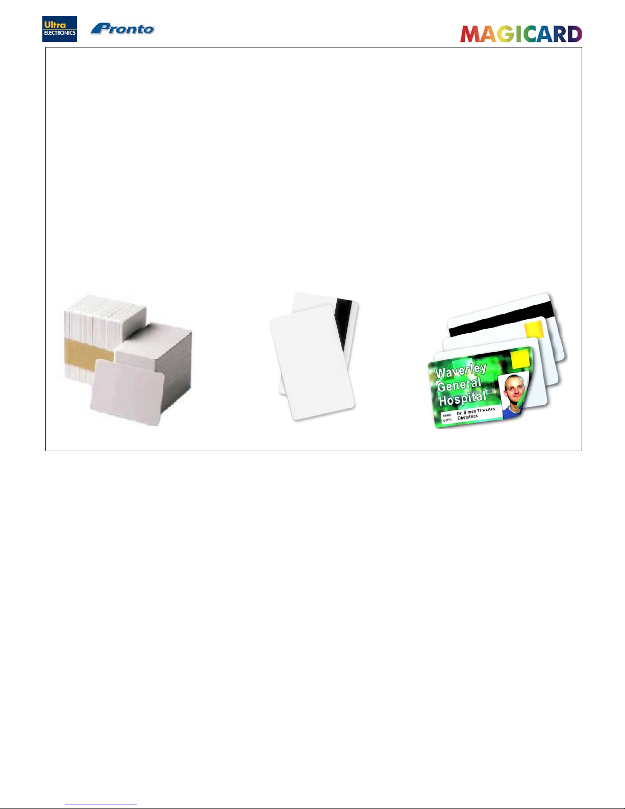
SECTION 4.2 CARDS
Card Material
Not all white plastic Cards are the same. For best image quality always use high quality grade PVC Cards.
Pure PVC Card stock or laminated PVC/Polyester Cards are available. The latter are more durable and better suited to
heavy use and heat lamination when required. For access control and “Smart Card” applications, your Dealer should
provide the appropriate type for “Direct to Card” printing. For good consistent results, keep to a single variety of good
quality Cards, such as those available from your Magicard Dealer.
Card Size
Card Thickness
Minimum 0.51mm 0.020”
Standard 0.76mm 0.030”
Maximum 1.02mm 0.040”
To obtain good quality prints the Cards must be :
Glossy white.
Free from dirt or grease.
Free from surface contamination, e.g. finger marks.
Free from burrs at the edge of the Card.
Free from
p
its or bumps in the surface.
Printable Area of the Card
The Pronto Printer offers high quality edge to edge (full bleed) printing.
Thus the surface of the Card may be printed “edge to edge”.
Die cut PVC Cards typically have an edge roll off (bevel) which can result in a fine white line around the edge of full bleed
printed Cards. When setting up your Card design using your graphics software on your PC, you should use a maximum
page size of 1016 pixels (3.375”/85.6mm) x 642 pixels (2.125”/53.98mm).
Ultra Electronics Ltd
Pronto Maintenance Manual
- 17 -
Other Card Types
Self-Adhesive Cards
We recommend only self adhesive Cards supplied by Ultra Electronics via your MagiCard Dealership. There are many
different types of self-adhesive Cards. Thorough investigation and testing has shown that poorer quality or incorrect Card
types will cause problems in the Printer. These problems range from poor image quality, Dye Film being cut, through to
Cards getting jammed in the Roller mechanism.
Contact Chip Cards
“Smart Cards” must conform to the ISO 7816 specification, with the chip contacts being below the surface of the Card. It is
unwise to print graphics or text directly adjacent to the chip as image quality may be affected.
Ultra Electronics Ltd
Pronto Maintenance Manual
- 18 -
SECTION 5 PHILOSOPHY
SECTION 5.1 REPAIR AND MAINTENANCE
The repair and maintenance philosophy for the Magicard Pronto is for repairs to be carried out by the replacement of
defective modules. The Printer has been specifically designed to comprise of several major modules :
The external Power Supply Unit (PSU).
The Main Control PCB.
The Print Engine Assembly.
The Thermal Print Head.
Field Repair
Every precaution has been taken in the design of the Pronto Printer to ensure user problems are rare. We have also tried
to anticipate any possible problems in the field, due to misuse, accidental failure or component failure. This Manual
should enable the Service Agent to identify any module or component that has failed, replace it, and carry out the
appropriate setting up and testing to ensure satisfactory operation.
Feedback
Ultra Electronics Limited is committed to the manufacture of quality products and encourages feedback of any problem or
faults occurring in the field, in order that we can improve the quality of our design, manufacture and support.
We would be grateful if the Service Agent would give full details of all faults when returning the Printer to us for repair.
We also provide a Customer Support service to help Customers in case they are having problems with their Printer.
You will find helpful information on our web-site: www.magicard.com
Conta
c
t Magicard Customer Support on the following numbers :
UK : Tel : +44 (0) 1305 762115
Fax : +44 (0) 1305 777904
E-Mail : customer_service@ultra.co.uk
USA :
Tel :
+001 425 556 9708
Fax : +001 425 556 3962
E-Mail : ussupport@ultramagicard.com

Ultra Electronics Ltd
Pronto Maintenance Manual
- 19 -
SECTION 6 WARRANTY INFORMATION
SECTION 6.1 THE WARRANTY
Coverage
Ultra Electronics Ltd warrants that the MAGICARD Printer shipped with this warranty statement will conform to the
manufacturers specifications and be free from defects in materials or workmanship for a period of 24 months from the
date of original purchase by the user. There are additional conditions on the Print Head warranty (see Para 2).
Limited Print Head Warranty
Ultra warrants that, under normal use and service, thermal Print Heads will be free from defects in material and
workmanship for a period of 12 months from the date of original purchase or for a quantity of 40,000 printed Cards,
(whichever comes first), provided that Ultra-approved card media is utilised. If a warranty claim is submitted for a
defective Print Head, Ultra will have the right to inspect the Print Head and samples of the printed and blank ID Cards
used with it for the purpose of verifying that the claimed defect has not been caused by non-Ultra approved media, or by
foreign particles or substances which have caused ch emical or physical damage. Ultra's decision in any such claims
shall be final.
Warranty Claims
If the MAGICARD Printer proves defective during this period, please contact Magicard Customer Support, at the address
and telephone/Fax number given below. The Customer Support personnel may first ask you to carry out certain simple
checks to confirm the nature of the problem, and if a return is appropriate, they will give you a “Magicard Return
Authorisation Number” (MRAN) and consignment instructions to the appropriate repair cent re. Ultra will, at it’s discretion,
repair or replace the defective parts at no charge to the Customer.
Warranty Limitations
The warranty does not apply to MAGICARD Printers that have been :
Damaged through physical or electrical mishandling.
Damaged through operation in environments that are outside normal office conditions in terms of corrosive
atmosphere, temperature, humidity, shock or vibration.
Improperly installed or interfaced to other products which may exhibit software problems or expose the
MAGICARD to improper voltages or control signals.
Fitted with Dye Film from any source other than Ultra Electronics, or have been used to print on anything other
than Card surfaces which are approved by Ultra and which will generally be made of PVC, be completely flat, and
be free of harmful particles or substances.
Serviced by anyone other than an Ultra Authorised Service Provider.
Shipping
Insurance and shipping costs incurred in sending the MAGICARD printer for warranty service is the responsibility of the
customer. Whenever possible, Magicard Customer Support will use the same class of shipping service selected and paid
for by the customer to return the Printer. Return shipping costs from Ultra to the customer will be at Ultra's expense.
After obtaining a “Magicard Return Authorisation Number” (MRAN) as described above, the Printer should be securely
packed in it’s original packaging with proof of date of purchase and a note describing the problem and quoting the MRAN
number. The Printer must be sent to the Service Centre address supplied with the MRAN. This address may be different
to the address listed below, but will generally be closer to you. Please also mark the MRAN number on the outside of the
shipping carton. All Customs Duties and Taxes, if applicable, are the responsibi lity of the Customer.

Ultra Electronics Ltd
Pronto Maintenance Manual
- 20 -
Applicability
The warranty and remedy provided above are exclusive and in lieu of all other warrants, either expresses or implied,
including but not limited to, implied warranties of merchantability and fitness for a particular purpose. Any statements or
representations made by any other person or Business are void.
Neither Ultra Electronics Limited nor its affiliates shall be liable for any loss, inconvenience, or damage, in cluding direct,
special, incidental, or consequential damages, resulting from the use or inability to use the Ultra product, whether
resulting from breach of warranty or other legal theory even if Ultra has been advised of the possibility of such damage or
loss.
This warranty is governed by English Law. Any dispute arising out of or relating to this warranty shall be submitted for
arbitration of this dispute or disputes pursuant to the rules and regulations of the UK Arbitration Act.
This warranty gives you specific legal rights, and you may also have other legal rights that vary from country to country so
the above limitations and exclusions may not apply to all Customers.
For warranty enquiries please call or Fax our Customer Support Manager : -
Ultra Electronics Limited
MAGICARD Service Centre
Waverley House
Hampshire Road
Granby Estate
WEYMOUTH
Dorset, DT4 9XD, U.K.
Tel : +44 (0) 1305 784738
Fax : +44 (0) 1305 777904
SECTION 6.2 INTERNET SUPPORT
To further enhance the Customer Support already available to Magicard Customers, the Magicard Web site contains
useful information on both problem solving and operation of the Pronto Printer. The web-site is available 24 hours per
day at www.magicard.com
SECTION 6.3 RECOMMENDED TOOLS
The following tools are recommended to support the Magicard Pronto in the field.
IBM PC or IBM Compatible Clone :
Pentium 600 MHz or faster (with USB Ports).
128 Mbytes memory or higher.
10 Gigabyte Hard Drive.
8 speed CD ROM or faster.
SVGA monitor with greater than 800 x 600 screen resolution.
Recommended PC Software :
Microsoft Windows (32-Bit) software (Win 2000 onwards).
Pronto Driver for Windows.
Magicard Support Utility SIN1926 (loaded separately via the Driver).
Graphics program such as Adobe Photoshop, Corel Draw or Paint Shop Pro.
Microsoft Office.
Badge Printing Application.
Engineers Tool Kit :
Anti-Static wrist strap.
Pozi blade screwdriver, preferably 150mm length (min.)
Torx Driver - Size 10.
Long nosed pliers.
Multimeter or Voltmeter.
Service Centre and Master Dealers :
McBeth Densitometer Model RD 1245 for calibration of the thermal Print Head printing density.
ISO Standard Magnetic Encoding Stripe Reader.
Ultra Electronics Ltd
Pronto Maintenance Manual
- 21 -
Three Cleaning Cards and a cleaning Roller are included with each new Pronto Printer. You can purchase additional
Cleaning Kits, which includeCleaning Cards, Rollers and Pens.
Cleaning Kits
Part Number CK1 (10 Cleaning Cards, 5 Rollers and a Cleaning Pen).
Part Number 3633-0054 (Cleaning Roller Kit – 5 sleeves and 1 Roller Bar).
SECTION 7 CLEANING THE PRINTER.
SECTION 7.1 CLEANING IS IMPORTANT
The most important procedure you can do to ensure Card print quality and the ongoing reliable operation of your Printer is
to perform regular cleaning cycles to remove dust and debris from the print Rollers.
Plastic Cards attract dust. Dust then gets ‘printed’ into the Card surface causing unsightly blemishes and possible
damage to the Print Head.
Your Magicard Printer has built-in cleaning Rollers to remove dust from the Card stock. These Rollers need to be
replaced periodically to remove the dust and debris accumulation.
Cleaning is Easy and Inexpensive
If you have not already done so, order a Cleaning Kit – see the ‘Cleaning Supplies’ – Section 7.2.
A clean Printer produces better quality Cards, as dust and dirt are not present when the Card is being printed.
A clean Printer is much less likely to require factory maintenance, and the Print Head in your Printer will last for many
years of normal use. Remember, large particles of dirt can damage the Print Head.
Magnetic encoding also degrades rapidly if the Printer has not been cleaned.
The Magicard Cleaning System
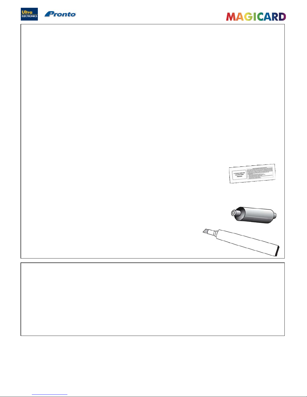
There are three main items included in your Printer’s Cleaning Kit - a Cleaning Card, a Cleaning Roller and a
Cleaning Pen :
A Cleaning Card is used to remove dirt from the print path. This should be used
after every 300 (prints per roll of Dye-Film). If you print only a few Cards a day, we
recommend that you clean the Printer more often.
There is a disposable Cleaning Roller in the Printer, which should be replaced after
every 1000 prints (approx. after using 3 rolls of Dye-Film). One cleaning Roller is provided
with each new roll of Dye Film.
There is also a Cleaning Pen, which is used to clean the Print Head. We recommend
you use this if any lines or discolorations are seen on printed Cards.
Follow the instructions on page 22 for cleaning the Printer.
SECTION 7.2 CLEANING SUPPLIES

Ultra Electronics Ltd
Pronto Maintenance Manual
- 22 -
SECTION 7.3 CLEANING THE PRINTER ROLLERS
Step 1 : Using the Cleaning Card
We recommend that you clean your Printer using a Cleaning Card after every 300 prints or each time you replace the
Dye-Film. You should do this more often if you print only a few Cards a day.
1. Open the lid and lift out the Dye-Film. Leave the lid open.
2. Take a new Cleaning Card from it’s packaging.
3. Open the “Printing Preferences…” (within the Driver) and select the “Printer” Tab. Click “Clean the Printer” Button.
4. Place the narrow end of the Cleaning Card into the front Card feeder slot.
The Card will automatically enter the Printer and the Rollers will be cleaned.
When the cleaning cycle is finished, the Cleaning Card will be ejected.
Turn the Cleaning Card over and repeat steps 2 – 4.
5. Close all Driver windows.
Ultra Electronics Ltd
Pronto Maintenance Manual
- 23 -
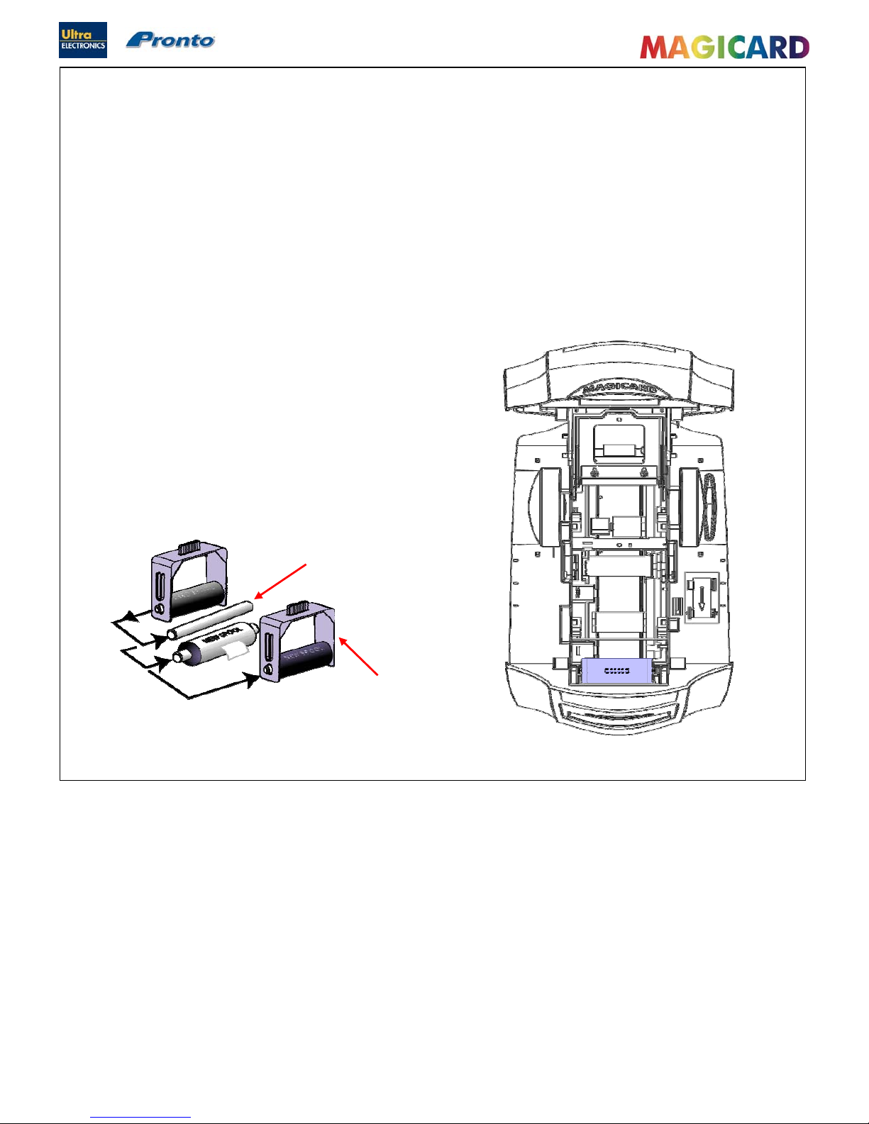
SECTION 7.4 REPLACING THE CLEANING ROLLER
Step 2 Fitting a new Cleaning Roller.
There is a Cleaning Cassette inside the Printer which holds a Cleaning Roller. We recommend that this Roller is replace d
after every 1000 prints, or sooner if it looks dirty.
You can re-use the cassette (you simply replace the Roller within it).
1. Open the Printer Lid and remove the used Dye-Film. Pull out the
Cleaning Roller Cassette.
2. Remove the “Sticky” Roller and then remove it’s central Roller Bar
3. Slide the central Roller Bar through the middle
of the new “Sticky” Roller. Refit Roller to Cassette.
4. Carefully remove the protective paper layer to reveal
the sticky surface.
5. Refit the Cleaning Cassette into the
Printer.
Central Roller
Bar
Cleaning
Cassette
Ultra Electronics Ltd
Pronto Maintenance Manual
- 24 -
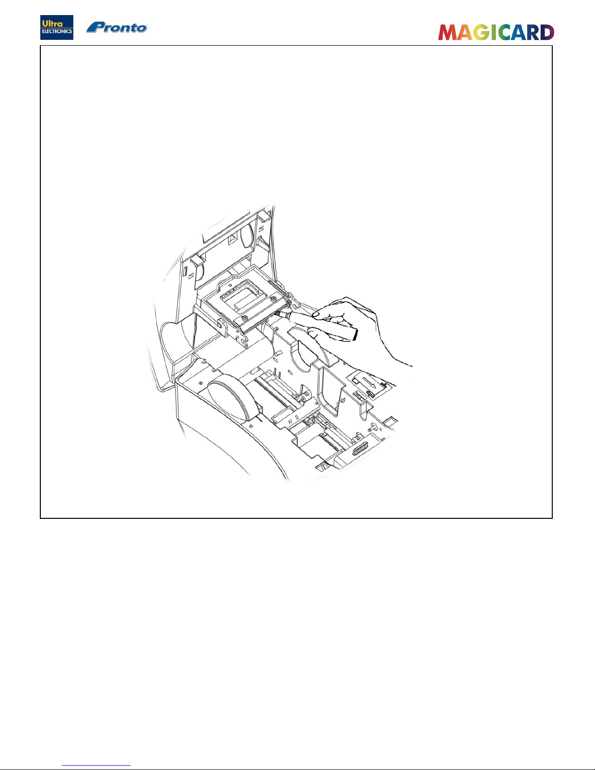
SECTION 7.5 CLEANING THE PRINT HEAD.
Step 3 Cleaning the Print Head.
The Print Head should be cleaned if any lines or discolorations are seen on printed Cards.
It is also a good idea to clean the Print Head when you replace the Dye-Film.
1. Use the special Print Head cleaning Pen from your Magicard Printer Cleaning Kit. See Section 6.1 ‘Cleaning
Supplies’.
2. Open the Printer and draw the Pen several times across the complete length of the Print Head .
Cleaning the Printer’s Print
Head with a Cleaning pen
Ultra Electronics Ltd
Pronto Maintenance Manual
- 25 -
Please Note : Windows 3.11, 95, 98, ME, and NT are not supported.
Ensure the Printer is powered off.
SECTION 8 MAGICARD PRONTO DRIVER.
Pronto and Pronto Mag use the new “UltraDriver”. This Driver is for use on the following Operating Systems only :
Windows 2000 & Windows XP (32 bit only).
Windows 2003 Server (32 bit only).
Windows Vista (32 bit only).
Windows 7 (32 bit only).
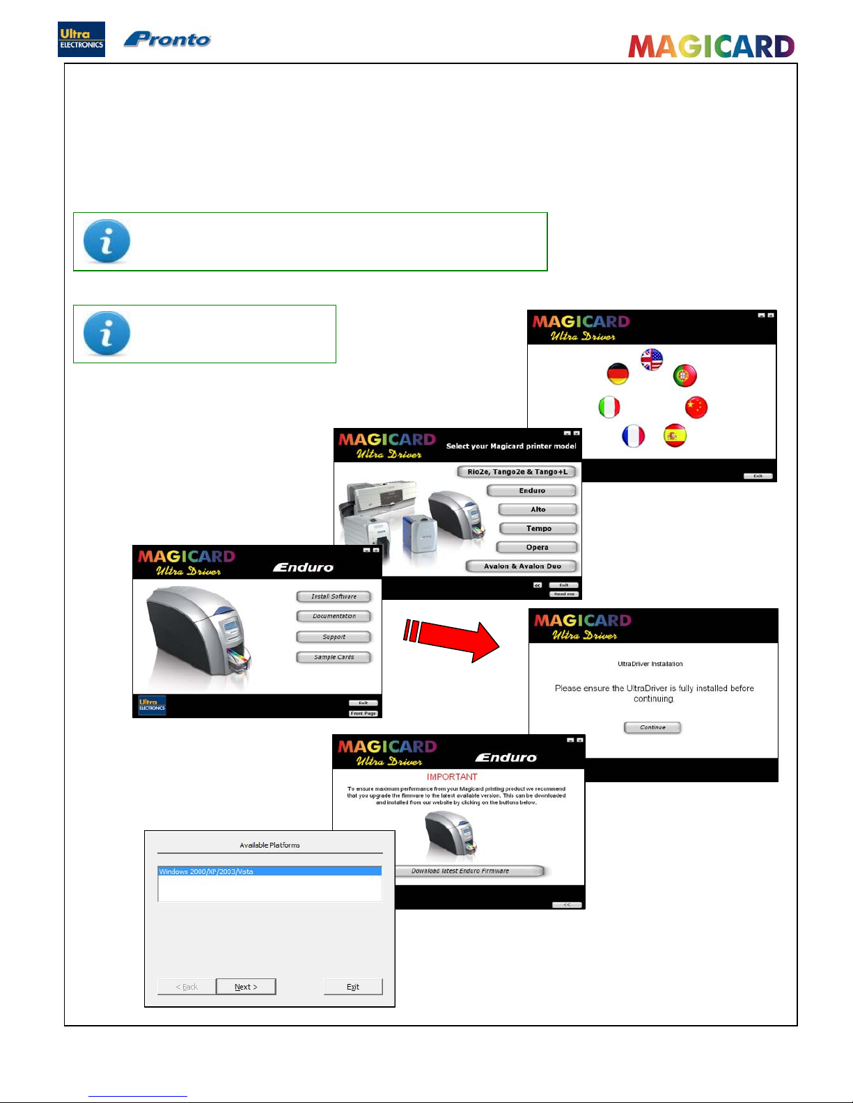
SECTION 8.1 INSTALLATION INSTRUCTIONS ARE THE SAME FOR ALL WINDOWS O.S.
Load the Driver CD ROM into the PC you have connected to the
Printer.
If the CD does not run automatically, click the “START” Button, then
click “Run”. Type “D:\autorun” (where D is
the Drive letter for your CD Drive), then
press the “Return” key.
Choose the language you wish to use.
Ultra Electronics Ltd
Pronto Maintenance Manual
- 26 -
Windows Vista
NOTE
If the Computer you are configuring for a USB connection to the Magicard Printer has
at some time run another manufacturer’s Printer (e.g. Eltron C-Series Printer), a
Windows file necessary for the Magicard installation could be missing.
(The symptoms of this are that the Computer does not seem to detect the Printer’s USB connection, and the
“Test Page” fails to print).
Recover the file as follows :-
Navigate to c:\windows\inf (Windows XP) or c:\winnt\inf (Windows 2000).
Find the file named “usbprint.in”, and then rename it to < usbprint.inf. >
Reconnect the USB cable.
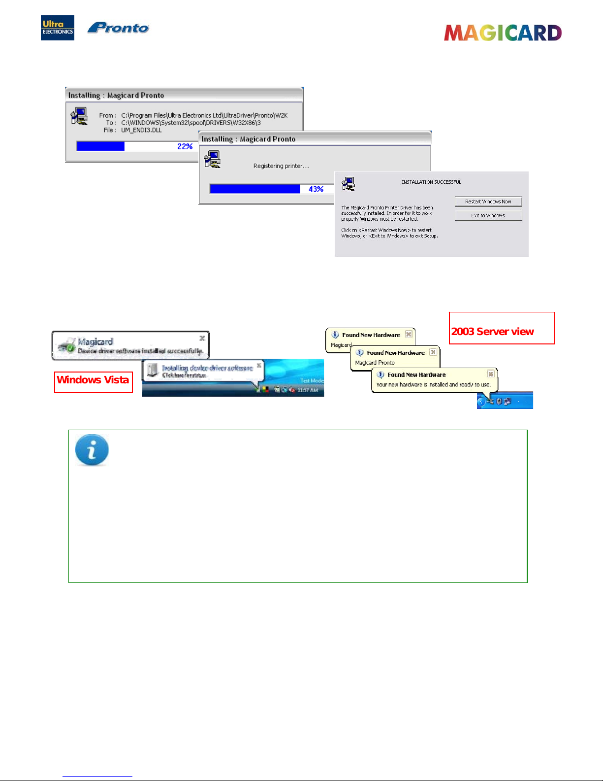
SECTION 8.1 INSTALLATION INSTRUCTIONS (CONTINUED…)
Ensure the Printer is switched on and showing “Ready” on the front LCD Display. The Printer can now be connected to
the PC.
Windows 2000 / XP /
2003 Server view
Ultra Electronics Ltd
Pronto Maintenance Manual
- 27 -
Ensure the Printer is disconnected.
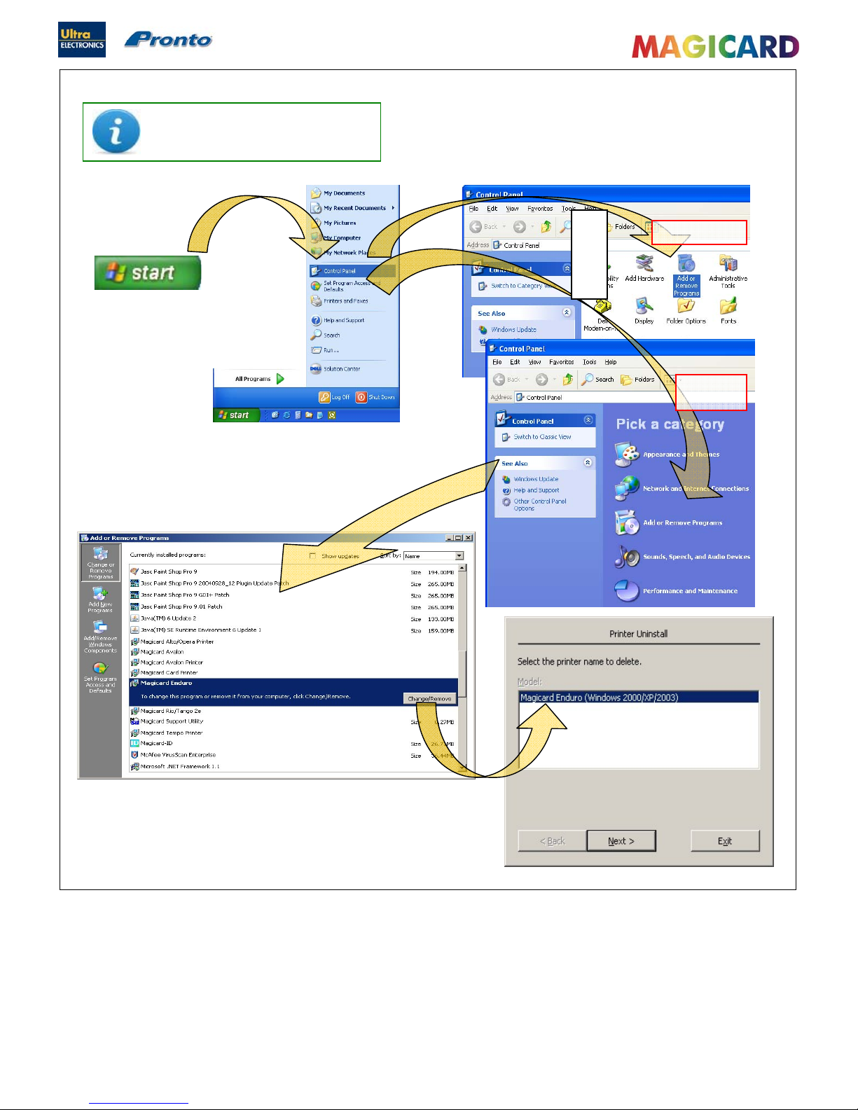
SECTION 8.2 UN-INSTALLING THE DRIVER FOR WINDOWS 2000 / XP / 2003 SERVER.
On the PC, go to “START”
>> “Control Panel”
Then select “Add or Remove Programs”
Classic view
Category
view
Select the “Magicard Printer entry,
and click on “Change/Remove”
Choose the “Magicard Printer you wish to
remove (there may be more than one),
and click “Next”
Lastly - simply follow the on-screen prompts !
or
 Loading...