

Page 1

Disposal / WEE declaration
Rechargeable Batteries and Batteries
The supplied rechargeable batteries or batteries are recyclable. Please
dispose of them at special waste collection points or your local dealer.
Only dispose of exhausted batteries or rechargeable batteries to ensure
environmental protection.
WEEE-Declaration
Your product is designed and manufactured with materials and
components of high quality, which are recyclable and can be reused.
The symbol means that your product should be disposed of separately
from household waste when it reaches its end of life. Please dispose of
this equipment at your local collection point or recycling center. Please
help to protect the environment in which we all live.
CE
All specifications and appearances are subject to change without
notice. All information was correct at time of printing. Musikhaus Kirstein
GmbH does not guarantee for the accuracy or completeness of any
description, photograph or statement contained in this manual. Printed
colors and specifications may vary slightly from product. Products from
Musikhaus Kirstein GmbH are only sold through authorized dealer.
Distributors and dealers are not agents of Musikhaus Kirstein GmbH
and have no authority to bind Musikhaus Kirstein GmbH legally in any
way. This manual is protected by copyright. Any copying or reprint, even
in excerpts, is only allowed with written consent of Musikhaus Kirstein
GmbH. The same applies to reproduction or copying of images, even in
altered form.
Pronomic PMX-1804FX
Users manual
00024066
Version 01/2012
Page 2
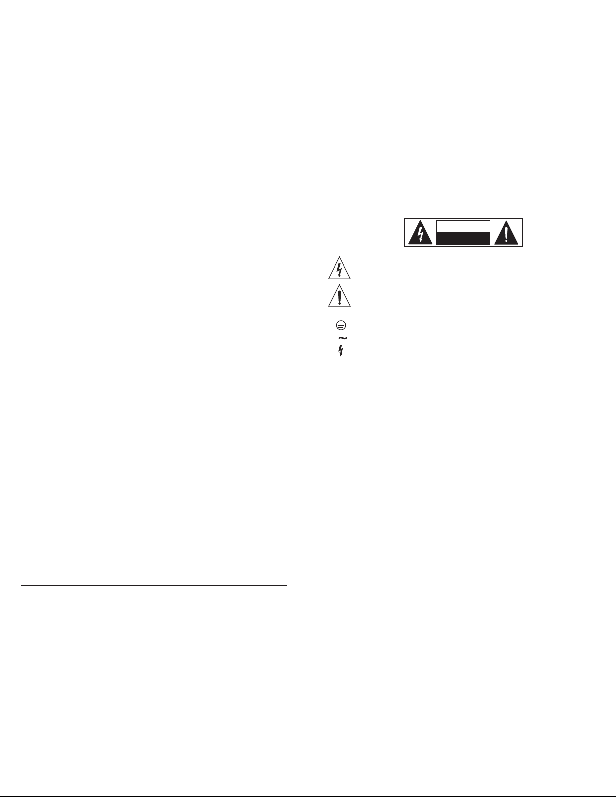
The symbol is used to indicate that some hazardous live terminals are
involved within this apparatus, even under the normal operating conditions,
which may be sufficient to constitute the risk of electric shock or
death.
The symbol is used in the service documentation to indicate that specific
component shall be replaced only by the component specified in that
documentation for safety reasons.
Protective grounding terminal
Alternating current/voltage
Hazardous live terminal
ON: Denotes the apparatus is turned on
OFF: Denotes the apparatus is turned off.
WARNING: Describes precautions that should be observed to prevent the danger
of injury or death to the operator.
CAUTION: Describes precautions that should be observed to prevent danger of
the apparatus.
IMPORTANT SAFETY INSTRUCTIONS
·Read these instructions.
·Keep these instructions.
·Heed all warning.
·Follow all instructions.
Water & Moisture·
CAUTION
RIS K OF ELEC TRIC SH OCK
DO NO T OPEN
IMPORTANT SAFETY SYMBOLS
The apparatus should be protected from moisture and
rain, can not used near water, for example: near bathtub, kitchen sink or a swimming pool, etc.
·Heat
The apparatus should be located away from the heat source such as radiators,
stoves or other appliances that produce heat.
PMX Se r i e s M ixer
18
Physical
PMX1204FX
Dimensions (H x W x D) 251 x 324 x 89 mm
3.5 kg
weight (net)
PMX1404FX
Dimensions (H x W x D)
312 x 324 x 102 mm
5.5 kgweight (net)
PMX1604FX
Dimensions (H x W x D)
365 x 324 x 102 mm
5.8 kgweight (net)
PMX1804FX
Dimensions (H x W x D)
418 x 324 x 102 mm
6.4 kgweight (net)
Output Power
THD+N +A
2 x 100W
2 x 300W
2 x 300W
PMX1204FX
PMX1404FX
PMX1604FX
PMX1804FX
2 x 300W
PMX1204FX
PMX1404FX
PMX1604FX
PMX1804FX
0.5%
0.1%
0.1%
0.1%
S/N +A
PMX1204FX
PMX1404FX
PMX1604FX
PMX1804FX
> 80 dB
Frequency
20Hz-20KHz (+0, -1dB)
Measuring conditions:
1: 1kHz rel.to 0 dBu; 20 Hz - 20 kHz, line input; main output; unity gain.
2: 20Hz - 20kHz; measured at main output. Channels 1 - 4 unity gain: EQ flat; all channels on main mix;
channels 1/3 as far left as possible, channels 2/4 as far right as possible. Reference = +6 dBu.
> 80 dB
> 80 dB
> 80 dB
Page 3

Main outputs
Type
Impedance
Max.output level
XLR electronically balanced
approx. 240 bal./ 120 unbal. Ω Ω
+28 dBu
Control room outputs
Type
Impedance
Max.output level
1/4"TS connector, unbal.
approx. 120 Ω
+22 dBu
Stereo aux return
1/4" TRS connector, electronically balanced
Type
approx. 20 k bal. /10 k unbal. Ω Ω
+22 dBu
Impedance
Max.input level
Headphones output
Type
Max.output level
1/4" TRS connector, unbalanced
+19 dBu / 150 (+25 dBu)Ω
Type
Impedance
Max.output level
1/4" T S connector, unbalanced
approx. 20 k Ω
+22 dBu
Aux sends
·Power Supply
The apparatus should be connected to the power supply only of the type as marked
on the apparatus or described in the manual. Failure to do could result in damage
to the product and possibly the user.
Unplug this apparatus during lightning storms or when unused for long periods
of time.
·Ventilation
Do not block areas of ventilation opening. Failure to do could result in fire. Always
install accordance with the manufacturer's instructions.
·Fuse
To prevent the risk of fire and damaging the unit, please use only of the recommended fuse type as described in the manual. Before replacing the fuse, make
sure the unit turned off and disconnected from the AC outlet.
·Electrical Connection
Improper electrical wiring may invalidate the product warranty.
·Cleaning
·Object and Liquid Entry
Clean only with a dry cloth. Do not use any solvents such as benzol or alcohol.
·Servicing
Do not implement any servicing other than those means described in the manual.
Refer all servicing to qualified service personnel only.
·Only use accessories/attachments or parts recommended by the manufacturer.
·Warning
Please remember the high sound pressure do not only temporarily damage your
sense of hearing, but can also cause permanent damage. Be careful to select a
suitable volume.
Objects do not fall into and liquids are not spilled into the inside of the apparatus
for safety.
·Power Cord and Plug
Protect the power cord from being walked on or pinched particularly at plugs, convenience
receptacles, and the point where they exit from the apparatus.
Do not defeat the safety purpose of the polarized or grounding-type plug. A polarized plug has two blades with one wider than the other. A grounding type plug
has two blades and a third grounding prong. The wide blade or the third prong is
provided for your safety. If the provided plug does not fit into your outlet, refer to
electrician for replacement.
PMX Se r i e s M ixer
17
24-bit Texas Instruments
24-bit Sigma-Delta.
64/128-times oversampling
40 kHz
DSP
Converter
Sampling rate
-105 dB / -108 dB A-weighted
-95 dB / -97 dB A-weighted
-82.5 dB / -85 dB A-weighted
2
Main mix system data
Noise
Main mix @ -∞,
Channel fader -∞
Main mix @ 0 dB,
Channel fader -∞
Main mix @ 0 dB,
Channel fader @ 0 dB
100 -240 V~, 50/60 Hz
200 W
Standard IEC receptacle
100 -240 V~, T10AH 250V
100-240 V~, 50/60 Hz
1000 W
Power supply
PMX1204FX
Mains voltage
Power consumption
Fuse
Mains connection
PMX1404FX/PMX1604FX/PMX1804FX
Mains voltage
Power consumption
Fuse
Mains connection
Standard IEC receptacle
100-120V, T10AH
200-240V, T5AH
Page 4

TABLE OF CO NTENTS
1.INTRODUCT IO N. .. .. ........... .. .. .. .. ........... .. .. .. .. ............. .. .. .. .. ..........2
1.1 G enera l mixin g conso le func tions ..... ..... ..... ..... .. ... ... ..... ..... ..... ..... .. ... ... ..... ..... ....3
1.2 T he us er’s m anu al... ..... ..... ..... .. ... ... ..... ..... ..... ..... .. ... ... ..... ..... ..... ..... ..... .. ... ... .... 3
1.3 B efore y ou get st arted ..... ..... ..... .. ... ... ..... ..... ..... ..... .. ... ... ..... ..... ..... ..... ..... .. ... ... ..3
1.3 .1 Ship ment .... ... ... ..... .. ... ... ..... ..... ..... ..... ..... .. ... ... ..... ..... ..... ..... .. ... ... ..... ..... ..3
1.3 .2 Init ial ope ratio n.... ..... ..... ..... .. ... ... ..... ..... ..... ..... .. ... ... ..... ..... ..... ..... ..... .. ... .. 3
3.DIGITAL EFFECTS PROCE SS OR .. .. ........... .. .. .. .. ............. .. .. .. .. ....13
4.INSTAL LTION....... .. .. .. .. ........... .. .. .. .. ........... .. .. .. .. ............. .. .. .. ..... 14
4.1 R ack mou nting ..... ..... ..... ..... .. ... ... ..... ..... ..... ..... .. ... ... ..... ..... ..... ..... ..... .. ... ... ... . 1 4
4.2 .1 Audio c onnec tions ..... ..... ..... ..... .. ... ... ..... ..... ..... ..... ..... .. ... ... ..... ..... ..... ....1 4
4.2 C able co nnect ions. ..... ..... ..... ..... .. ... ... ..... ..... ..... ..... .. ... ... ..... ..... ..... ..... ..... .. ... . 14
PMX Se r i e s M ixer
2.CONTROL ELE ME NTS AND C ON NECTORS .. .. .. .. ........... .. .. .. .. ..... 3
2.1 M ono cha nnels ..... ..... ..... ..... .. ... ... ..... ..... ..... ..... .. ... ... ..... ..... ..... ..... ..... .. ... ... ..... ..4
2.1 .1 Micr ophon e and lin e input ..... ..... ..... ..... .. ... ... ..... ..... ..... ..... ..... .. ... ... ..... ..... ..4
2.1 .2 Equa lizer. ..... ..... ..... ..... .. ... ... ..... ..... ..... ..... .. ... ... ..... ..... ..... ..... ..... .. ... ... ..... .4
2.1 .3 Aux sen ds... ..... ..... ..... .. ... ... ..... ..... ..... ..... ..... .. ... ... ..... ..... ..... ..... .. ... ... ..... ...5
2.1 .4 Rout ing swi tch, so le and ch annel f ader.. ..... ..... ..... ..... .. ... ... ..... ..... ..... ..... .. .. 5
2.2 S tereo c hanne ls... ..... ..... ..... .. ... ... ..... ..... ..... ..... ..... .. ... ... ..... ..... ..... ..... .. ... ... ..... ..6
2.2 .1 Chan nel inp uts.. ..... ..... ..... .. ... ... ..... ..... ..... ..... ..... .. ... ... ..... ..... ..... ..... .. ... ... ..6
2.2 .2 Equa lizer s tereo c hanne ls... ..... ..... ..... .. ... ... ..... ..... ..... ..... ..... .. ... ... ..... ..... ... 6
2.2 .3 Aux sen ds ster eo chan nels. ..... ..... ..... ..... .. ... ... ..... ..... ..... ..... .. ... ... ..... ..... .... 6
2.2 .4 Rout ing swi tch, so le and ch annel f ader.. ..... ..... ..... ..... .. ... ... ..... ..... ..... ..... .. .. 6
2.3 C onnec tor pan el and ma in sect ion.. ..... ..... ..... ..... .. ... ... ..... ..... ..... ..... .. ... ... ..... ..... .7
2.3 .1 Aux sen ds 1 and 2. ..... ..... ..... ..... .. ... ... ..... ..... ..... ..... .. ... ... ..... ..... ..... ..... ..... ..7
2.3 .2 Aux sen d conne ctors 1 a nd 2... ..... ..... ..... .. ... ... ..... ..... ..... ..... ..... .. ... ... ..... .....7
2.3 .3 Ster eo aux re turn co nnect ors.. ..... ..... ..... .. ... ... ..... ..... ..... ..... .. ... ... ..... ..... .....8
2.3 .4 Ster eo aux re turn. ..... ..... ..... .. ... ... ..... ..... ..... ..... .. ... ... ..... ..... ..... ..... ..... .. ... .. .8
2.3 .5 Tape i np ut / ta pe ou tp ut. ... ..... ..... ..... ..... .. ... ... ..... ..... ..... ..... .. ... ... ..... ..... ..... .9
2.3 .6 Leve l metre a nd moni torin g.... ..... ..... ..... .. ... ... ..... ..... ..... ..... .. ... ... ..... ..... ..... 9
2.3 .7 Alt 3-4 a nd main m ix fade r..... ..... ..... ..... .. ... ... ..... ..... ..... ..... .. ... ... ..... ..... ..... 11
2.4 R ear vie w of PMX1 204FX /1404 FX/16 04FX/ 1804F X.... ..... ..... .. ... ... ..... ..... ..... ..... 12
2.4 .1 Main m ix outp uts, Alt 3 -4 outp uts and r oom out puts. ..... ..... ..... .. ... ... ..... ..... . 12
2.4 .2 Volta ge supp ly, phan tom p ower an d fuse. ..... ..... ..... ..... ..... ..... .. ... ... ..... ..... . 12
2.4 .3 AMP out put ..... ..... ..... ..... ..... ..... .. ... ... ..... ..... ..... ..... .. ... ... ..... ..... ..... ..... ..... . 13
2.4 .4 Heat r emova l syste m.... ..... ..... .. ... ... ..... ..... ..... ..... ..... .. ... ... ..... ..... ..... ..... .. . 13
5.SPECIFICAT IO NS......... .. .. .. .. ........... .. .. .. .. ............. .. .. .. .. ........... .. .1 6
1
PMX Se r i e s M ixer
16
5.SP ECIFICATIO NS
Mono inputs
Microphone inputs (XENYX Mic Preamp)
Type XLR, electronically balanced,
discrete input circuit
Mic E.I.N. (20 Hz - 20 kHz)
@ 0 Ω source resistance
@ 50 Ω source resistance
@ 150 Ω source resistance
-134 dB / 135.7 dB A-weighted
-131 dB / 133.3 dB A-weighted
-129 dB / 130.5 dB A-weighted
Frequency response
<10 Hz -150 kHz (-1 dB),
<10 Hz -200 kHz (-3 dB)
Gain range
+10 to +60 dB
Max. Input level
+12 dBu @ +10 dB gain
Impedance
approx. 2.6 k balancedΩ
110 dB / 112 dB A-weighted
Signal-to noise ratio
(0 dBu In @ +22 dB gain)
Distortion (THD+ N) 0.005% / 0.004% A-weighted
Line input
Type
Impedance
Gain range
Max. Input level
1
Fade-out attenuation
(Crosstalk attenuation)
Main fader closed
Channel muted
Channel fader closed
Frequency response
Microphone input to main out
<10 Hz - 90 kHz
<10 Hz - 160 kHz
+0 dB / -1 dB
+0 dB / -3 dB
Stereo inputs
Type
1/4" TRS connector,
Impedance
Max. Input level
electronically balanced
approx. 20 k Ω
+22 dBu
EQ mono channels
EQ stereo channels
1/4" TRS connector,
electronically balanced
approx. 20 banlanced Ω
10 k unbanlanced Ω
-10 to +40 dB
30 dBu
90 dB
89.5 dB
89 dB
Low
Mid
High
Low
Mid
High
80 Hz / 15 dB
2.5 kHz / 15 dB
12 kHz / 15 dB
80 Hz / 15 dB
2.5 kHz / 15 dB
12 kHz / 15 dB
Page 5
1.INTRODUCTION
Congrat ulations! In purchas ing the MX you have acqu ired a mixe r whose sma ll size
incredib le versati lity and au dio perfor mance.
belies it s
The micr ophone ch annels fe ature hig h-end Mic Preamps that comp are well w ith costl y outboar d
preamps in terms of sound quality and dynamics and boast the following features.
* 130dB dynamic range for an incredible amount of headroom
*
nuances.
A bandwidth ranging from below 10Hz to over 200kHz for crystal-clear reproduction of over the finest
*
signal reproduction.
The extremely low-niose and distortion-free circuitry guarantees absolution natural and transparent
*
phantom power su pply.
They are perfectly matched to every conc eivable microphone w ith up to 60 dB gain and +48 volt
*
the full. Thereby maintaining optimal audio quality.
They enable you to use the greatly extended dynamic range of your. 24-bit/192kHz HD recorder to
The equalizers used for the MX Series are based on th e legendary circu itry of top-notch consoles
made in Britain, which are renowned throughout the world for their incredibly warm and musical sound
character. Even with extreme gain settings these equ alizers ensure ou tstanding audio quality.
Additionally, your PMX Series mixing consoles has an effects processor with 24-bit A/D and D/A converters included, which gives you 100 presets producing first-class reverb, delay and modulation effects
plus numerous multi-effects in excellent audio quality.
The PMX Series mixing consoles are equipped with a state-of-the-art switched-mode power supply
(SMPS). Unlike conventional circuitry an SMPS provides an optimum supply current regardless of the
input voltage. And thanks to its considerably higher efficiency a switched-mode power supply uses less
energy than conventional power supplies.
USB/Audio interface
Mutil-effects processor
“Bitish EQ”
The MX Series represents a milestone in the development of mixing console technology. With the new
microphone preamps including phantom power as an option. Balanced line input and a powerful effects
section. The mixing consoles in the MX Series are optimally equipped for live and studio applicatio ns.
Owing to state-of-the-art circuitry your MX console produces a warm analog sound th at is unrivall ed.
With the addition of the latest
of both analog and digital technology.
digital technology these base-in-class consoles combine the advantages
PMX Se r i e s M ixer
The USB inte rface supplie d with the unit is a perfec t matc h for the PMX Se ries and serve s as a
powerful recording interface to you PC or MAC. It supports the digital transmission of signals on up to
four channe l w ith max 4 8kHz and ex tremel y low lat ency. When wired to the CD/TAPE INPUT and
OUTPUT connectors, the interface transfers the stereo mix from the console directly to a computer. Both
the recording signals and the playback signal from the computer can be monitored at the same time. In
this way, you can use several recording runs to produce complete multi-track recordings.
We should like to draw your attention to the fact that extreme volumes may damage your
hearing and/or your headphones or loudspeakers. Turn the MAIN MIX faders and phones
control in the main section fully down before you switch on the unit. Always be careful to
set the appropriate volume.
2
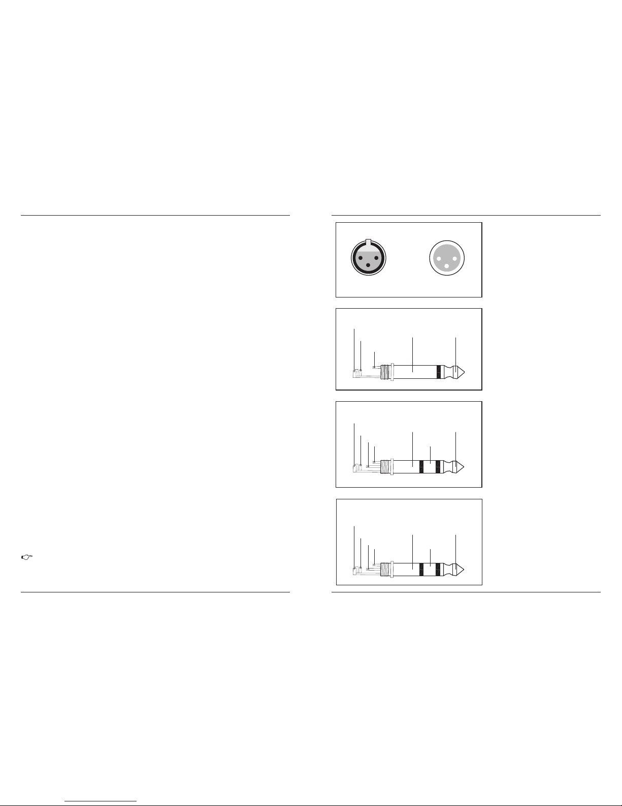
Fig . 4.4: 1/ 4" TRS c onnec tor
For connection of balanced and unbalanced plus,
rig and sleeve have to be bridged at the stereo plug
strain relief clamp
sleeve
tip
sleeve
tip
ground shield
hot (+ ve)
ring
cold (- ve)
ring
Balanc ed use of
1/4"T RS con nector
Fig . 4.3: 1/ 4" TS co nnect or
The foot switch connects the two poles momentarily
strain relief clamp
sleeve
tip
sleeve
tip
ground shield signal
Unbala nced use of
1/4"T RS con nector
Fig . 4.2: XL R conne ction s
For unbalanced use pin 1 and pin 3 have to be bridged
Balan ced use with X LR connec tors
1=grou d / shield
2=hot (+v e)
3=cold (- ve)
1
2
3
1
2
3
Input
Output
Hea dphon es conn ectio n
wit h 1/4" TR S con nec tor
strain relief clamp
sleeve
tip
sleeve
tip
ground shield
left signal
ring
right signal
ring
Fig . 4.5: 1/ 4" TRS c onnec tor for
hea dphon es
PMX Se r i e s M ixer
15
Page 6
1.1 general mixing console functions
A mixing console fulfils three main functions:
*Signal processing: Preamplification, level adjustment, mixing of effects. Frequency equalization.
*Signal dist ribution: Sum ming of signal s to the aux sends f or effects proce ssing and moni tor mix,
distribution to one or several recording tracks, power amp(s), control room and 2-track outputs.
*Mix: Setting the vol ume level, frequency di stribution and positi oning of the individual signals in the
stereo field, level control of the total mix to match the recording devices/crossover/power amplifier(s).
All other mixer functions can be included in this main function.
The interface of LONGERDB mixing consoles is optimized for these tasks enabling you to easily keep
track of the signal path.
1.2 The user’s manual
The user’s manual is designed to give you both an overview of the controls, as well as detailed information
on how to use them. In order to help you understand the links between the controls, we have arranged
them in groups according to their function.
1.3 Before you get started
1.3.1 Shipment
Your mixing console was carefully packed in the factory to guarantee safe transport. Nevertheless, we
recommend that you careful examine the packing and its contents for any signs of physical damage. Which
may have occurred during transit.
If the unit is damaged, please do NOT return it to us, but notify your dealer and the shipping
company immediately, otherwise claims for damage or replacement may not be granted.
1.3.2 Initial operation
Be sure that there is enough space around the unit for cooling purposes and to avoid over-heating please
do not place your mixing cons ole on high-temperature devices such as radia tors or power amps. The
console is connected to the mains via the supplied cable. The console meets the required safety standards.
Blown fuses must only be replaced by fuses of the same type and rating.
Please note that all unit must be properly grounded. For your own safety, you should never
remove an y ground connectors fro m electric al devices o r power cable s, or render t hem
inoperative.
Please sure that only qualified people install and operate the mixing console. During installation and op eration, t he user mu st have suf ficient e lectrica l contact to earth, otherwise
electrostatic discharges might affect the operation of the unit.
2.CONTROL ELEMENTS AND
CONNECTORS
This chapter describes the various control elements of your mixing console. All controls, switches and
connectors will be discussed in detail.
PMX Se r i e s M ixer
3
PMX Se r i e s M ixer
14
This also goes for mixing effects signals with the monitor mix. The main difference is that the mix radio
is adjusted using the FX TO MON control. Of course, a signal has to be fed into the effects processor via
the FX control in the channel strip for both applications.
You can select the effect preset by turning the PROGRAM control. The display flashes the number of
the current preset. To recall the selected preset, press the button; the flashing stops. You can also recall
the selected preset with the foot switch.
PRO GRAM
LEV EL
The LED level mater on the effects module should display a sufficiently high level. Take care to ensure
that the clip LED only lights up at peak levels. If it is lit constantly, you are overloading the effects processor
and this could cause unpleasant distortion. The FX control (AUX SEND 2) determines the level that reaches
the effects module.
On the following page, you will find an illustration showing how to connect your foot switch
correctly.
4.1 R ack mou nting
Before you can attach the rack mo unt wings to the mi xing console, you need to remove the screws
holding the left and right side panels. Use these screws to fasten the two wings onto the console, being
careful to note that each wing fits a specific side. With the rack mount wing installed. You can mount the
mixing console in a commercially available to allow for proper air flow around the unit,19" rack. Be sure
and do not place the mixing console close to radiators or power amps. So as to avoid overheating.
4.INSTALLATION
The packing of your mixing console contains two 19 " rack mount wings which can be installed on the
side panels of the console.
You will n eed a la rger n umber o f cabl e for th e various con nectio ns to a nd from the co nsole. The
illus trations bel ow show. T he wing of these cabl es. Be s ure to use onl y high -grade cable .
4.2 C able co nnect ions
Only use the screws holding the mixing console side panels to fasten the 19" rack mounts.
Please use commercial RCA cables to wire the 2-track inputs and outputs.
You can, of course, also connect unbalanced devices to the balanced input/outputs. Use either mono
plugs, or ensure that ring and sleeve are bridged inside the stereo plug (or pins 1 & 3 in the case of XLR
connectors).
4.2 .1 Audi o con nec tions
Caution! You must never use unbalanced XLR connectors (pin 1 and 3 connected) on the MIC
inputs if you in tend to use the phantom power supply.
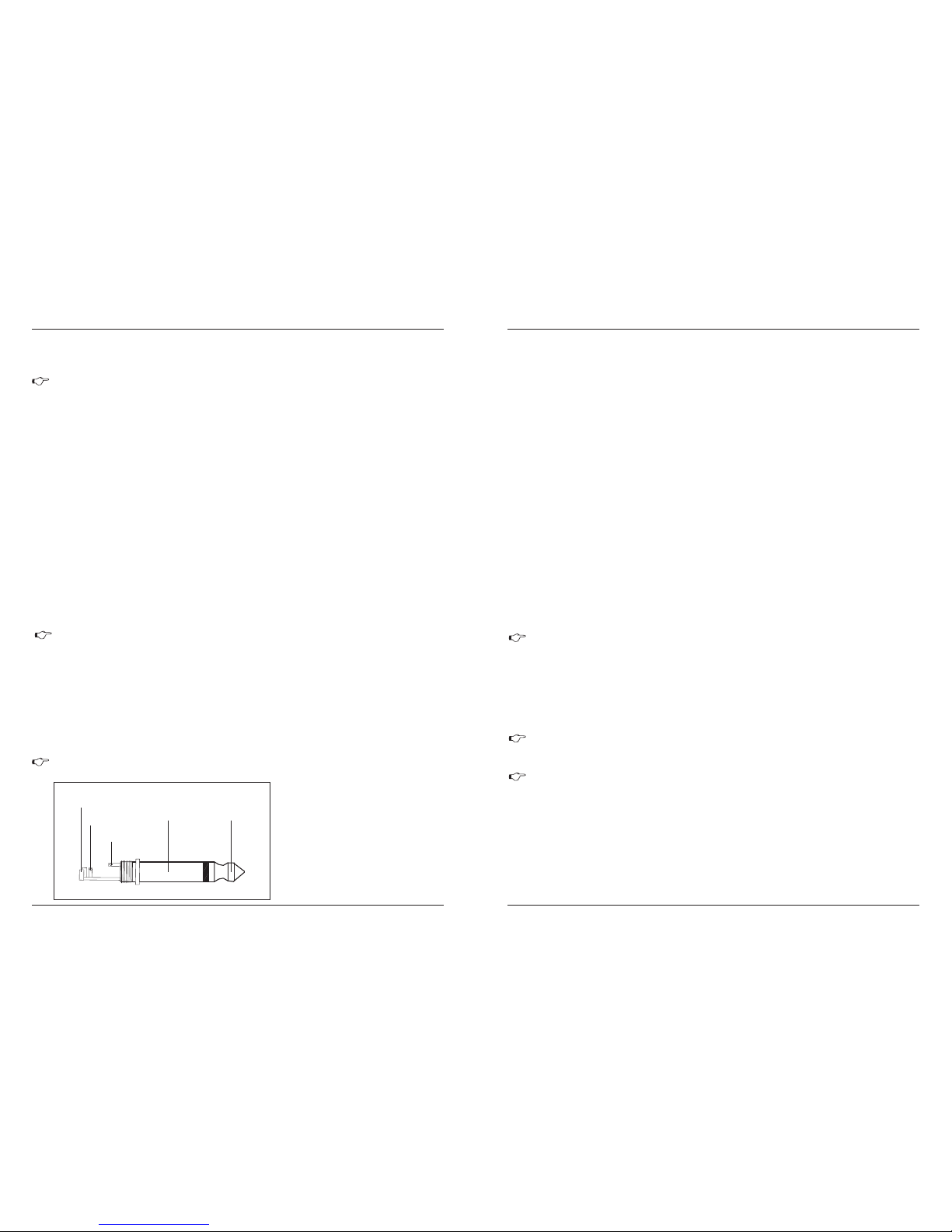
Fig . 4.1: 1/ 4" TS con necto r
for f oot swi tch
The foot switch connects the two poles momentarily
1/4" T S conne ctor fo r use wit h foot sw itch
strain relief clamp
sleeve
tip
sleeve
tip
pole 1/ground pole 2
Page 7
SPEAK OUTPUTS
L
R
Min load 4Ω
0
-15 +15
0
-15 +15
0
-15 +15
HIGH
12 KHz
EQ
MID
2.5 KHz
LOW
80 Hz
The mono channels of the mixing consoles have a highslope LOW CUT filter for eliminating unwanted,low-frequenty
signal components (75 Hz, 18 dB/octave).
LOW CUT
TRIM
Use the TRIM control to adjust the input gain. This control should always be turned fully counterclockwise whenever you connect or disconnect a signal source to one of the inputs.
Each mono input also features a balanced line input on a
1/4" connector. Unbalanced devices (mono jacks) can also
be connected to these inputs.
LINEIN
please rememb er that you can o nly use either th e
microphone or the line input of a channel at any one
time. You can never use both simultaneously!
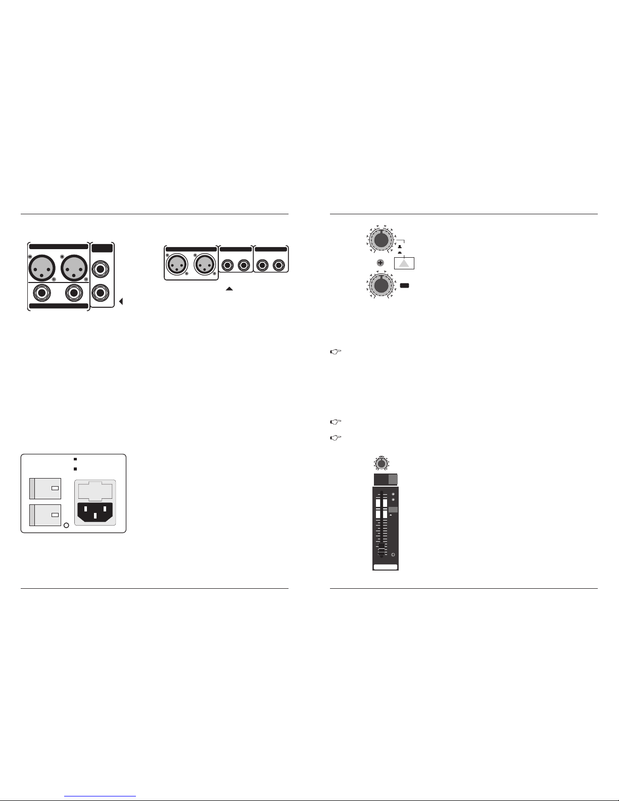
2.1 Mo no channe ls
2.1 .1 Micr ophon e and lin e input s
Fig . 2.1: Co nnect ors and
con trols o f mic/l ine inp uts
Each mono input channel offers a balanc ed microphon e
input vi a the XLR c onnector a nd also fe atures sw itchable
+48V pha ntom power supply for condense r micropho nes.
The PMX preamps provide undistorted and noised-free gain
as is typically known only from costly outboard preamps.
MIC
Plea se mut e you r play back syste m befo re yo u
active the phantom power supply to prevent switchon thump be ing d irec ted t o you r lou dspe akers.
Please also note the instr uctions in c hapter 2.4. 2
“Voltage supply, phantom power and fuse”.
+10 -40
MIC
+10 + 60
TRIM
dB/dB u
LOW CUT
75Hz
18 dB/ Oct
LINE I N
BAL
OR
UNBA L
1
PMX Se r i e s M ixer
4
All mono input channels include a 3-band equalizer. All bands provide boost or cut of up to 15dB. In the
central position, the equalizer is inactive.
The circuit ry of the Britis h EQs is based on the tec hnology used in the bast-kn own top-o f-the-l ine
consoles and providing a warm sound without any unwanted side effects. The result are extremely musical
equalizes which, unlike sim ple equalizers, cause no side effects such as phas e shifting or bandwid th
limitation, even with extreme gain settings of ±15 dB.
2.1.2 Equalizer
Fig . 2.2: Pa noram a and rou ting co ntrol s
The upper (HI) and the lower band (LO) are shelving
filters t hat increa se or decrease all fr equencies above
or below their cut-off frequency. The cut-off frequencies
of t he upp er a nd l ow er b and are 12 kHz and 80 H z
respectively. The mid band is configured as a peak filter
with a centre frequency of 2.5kHz
Fig . 3.1: Di gital e ffect s modul e
PROGRA M
(PUSH )
PHON ES
FX
FOOT SW
24 -B IT MULTI- FX PROCESSOR
00 SMALL H ALL
03 MID HAL L
06 BIG HAL L
09 CHURCH
10 SMALL RO OM
13 MID ROOM
16 BIG ROOM
19 CHAPEL
20 PLATE
27 SPRIN G
30 GATED RE V
36 REVERS E
40 EARLY REF L
44 AMBIE NCE
48 STAD IUM
49 AMBIENC E FX
50 DELAY
59 ECHO
60 CHORUS
66 FLANGER
70 PHASER
74 PITCH SHI FT
80 CHORUS & R EVERB
82 FLANGER & R EVERB
84 PHASER & RE VERB
86 PITCH & REV ERB
88 DELAY & REVE RB
90 DELAY & GATED
91 DELAY & REVE RSE
92 DELAY & CHORU S
94 DELAY & FLAN GER
96 DELAY & PHAS ER
98 DELAY & PITCH
CLIP
-
3
-
6
-
10
-
15
-
20
24-BIT DUAL E NGINE D SP
LEVEL
24-BIT A/D & D /A CONV ERTER
PMX Se r i e s M ixer
13
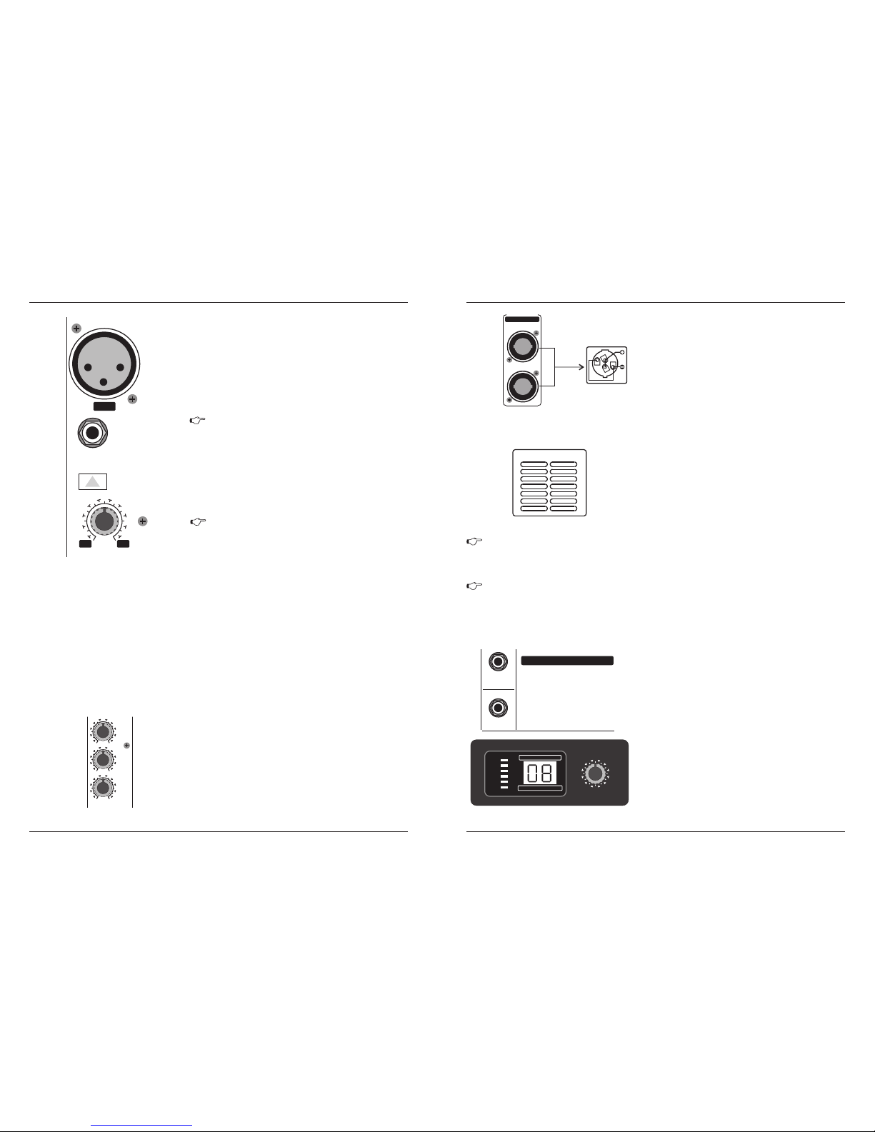
Fig . 2.16: A MP out put
AMP O UTPUT
This speakon soc ket is for stereo Am p L/R output. It's
used to connect speaker cabinet by speakon NL 4FC.
Note: Min Load 4Ω
2.4 .3 AMP Ou tpu t
HEAT R EMO VAL SY ST EM
This is the mixer's stereo amp fan refrigeration system.
It works with low speed in norm al temperature (≤45℃).
When it is higher than 45℃, it will quicken up.
Note: Keep the windhole free, or the equipment will be too
hot and turn to protection in advance.
Fig . 2.17: H eat rem oval sy stem
2.4 .4 Heat r emova l syste m
DO NOT OBSTRUCT AIR VENTS
SER IAL NUM BER
Please note the important information on the serial number given in chapter 1.3.3.
After the phantom power supply has been switched on, do not connect microphones to the
mixer (or the stagebox/wallbox). Connect the on. In addition, the monitor/PA loudspeakers
should be muted before activating the phantom power supply. After switching on, wait approx.
One minute to allow the system to Stabilize.
Caution! You must never use unb alanced XLR connecto rs (PIN 1and 3 connect ed) on the
MIC input connect ors if you want to use t he phantom power supp ly.
3.DIGITAL EFFECTS PROCESSOR
24- BIT MULT I-E FFECT S PROCE SSOR
These effect presets are d esigned to be added to dry
signals. If you move the FX TO MAIN control, you mix the
channel signal (dry) and the effect signal.
Here you can find a list of all presets stored in the multi-
effects proces sor. This built-in effects module produces
high-grade standard effects such as reverb, chorus, flanger,
delay and vari ous com bination effect s. The in tegrat ed
effects module has the advantage of requiring no wiring.
This way, the danger of creating ground loops or uneven
signal level is eliminated at the outset, completely simpli-
fying the handing.
+1
-1
-2
+2
Page 8
PMX Se r i e s M ixer
5
2.1 .3 Aux se nds
Aux sends take signals via a control from one or more
channels and sum these signals to a so-called bus. This
bus sign al is sent to an aux send conn ecto r and the n
routed, for example, to an active moni tor speaker o r an
external effects device. The return from an external effect
device can then be brought back into the console via the
aux return connectors.
For situations which require effects processing, the aux
sends are usually switched post-fader so that the effects
volume i n a channe l corresp onds to th e positio n of the
channel fader. if this were not the channel would remain
audible even when the fader is turned to zero. When setting
up a monitor m ix, the aux send s are generally switched
to pre-fader, i.e. they operate independently of the position
of the channel fader.
Both aux sends are mono, are sourced after the equalizer and offer up to +15dB gain.
Fig . 2.3: Th e AUX S END
con trols i n the cha nnel st rips
Aux send 1 can be switched pre-fader and is thus particularly suitable for setting up monitor mixes.
AUX 1 ( MON)
PRE
When the PRE switch is pressed, aux send 1 is sourced pre-fader.
The aux send labeled FX is for sending to effects devices and is thus set up to be post-fader.
Aux 2 ( FX)
If you press the MUTE/ALT 3-4 switch, aux send 1 is muted, provided that it is switched postfader. However, this does not affect the aux send 2
If you wish to use the internal effects processor, the STEREO AUX RETURN 2 connectors
should not be is use.
You can also connect an external effects processor to aux send 2, however the internal
effects module will be muted.
0
- +15
8
2
0
-8+15
AUX1
FX
POST
PRE
The MUTE LED indicates that the relevant channel is
diverted to the submix (Alt 3-4 bus).
MUT E-LED
You can use the MUTE/ALT 3-4 s witch t o driver t he
channel f rom the mai n mix bus to the Alt 3-4 bus . This
mutes the channel from the main mix.
MUT E/ALT 3- 4
The PAN control determines the position of the channel
signa l within the ste reo ima ge. This contro l featu res a
constant-power characteristic, which means the signal is
always maintained at a constant level, irrespective o position in the stereo panorama.
PAN
2.1 .4 Rout ing swi tch, so lo and ch an nel f ade r
Fig . 2.4: Pa noram a and
rou ting co ntrol s
L R
PAN
1
MUTE
ALT 3-4
1
dB10MUTE
CLIP
0
10
15
20
25
30
40
60
8
SOLO
PMX Se r i e s M ixer
12
Fig . 2.14 Ma in mix ou tputs , Alt 3 -4 ou tp uts a nd co nt rol r oom o utput s
2.4 Rea r vi ew of PMX 12 04FX/ PM X1404 FX /PMX1 60 4FX/P MX 1804F X
2.4 .1 main m ix outp uts, Al t 3-4 o utp uts and c ontro l room ou tputs
MAI N OUTPU TS
The MAIN outputs carry the MAIN MIX signal and are on balanced XLR connectors with a nominal
level of +4dBu.
ALT 3-4 OUTPUTS
The ALT 3-4 output are unbalanced and carry the signals of the channels that you have assigned to
this group using the MUTE switch. This can be used to route a subgroup to a further mixing console for
example, or it could be used as a recording output working in tandem with the main output. This means
you cou ld record to four t racks si multane ously. The ici ng on the cake, so to speak, is that y ou could
connect Y-cables to these four outputs and then connect your 8-tra ck recorder in such a way that you
have 2 x 4 tracks. (E.g. Channel 1 feeds track 1and track 2, etc.). In the first recording pass, you record
on track 1, 3.5 and 7 and in the second pass, on tracks 2, 4, 6 and 8.
CON TROL RO OM OU TPUT
The control room output is normally connected to the monitor system in the control room and provides
the stereo mix or, when required, the solo signal.
Fig . 2.15: V olt age sup ply a nd f use
2.4 .2 Volta ge su pply, ph ant om powe r and fus e
FUS E HOLDE R
The console is connect to the mains via the cable supplied
which meets the required safety standards. blown fuses must
only be replaced by fuses of the same type and rating.
The mains connection is via a cable with IEC mains con-
nector. An appropriate mains cable is supplied with equipment.
IEC M AINS RE CEPTAC LE
POW ER
Use the POWER switch to power up the mixing the console.
PHA NTOM
The PHANTOM switch activates the phantom power supply for the XLR connectors of the mono channels which is required to operate condenser microphones. The red +48 VLED lights up when phantom
power is on. As a rule, dynamic microphones can still be used with phantom power switched on, provided
that they are wired in a balanced configuration. In case of doubt, contact the microphone manufacturer!
PIN 2 = HOT / PIN 3 = COLD
MAIN OUTPUTS ALT 3-4
OUTPUTS
R
L
R
L
CONTROL ROOM OUT
4
3
POWER
ON
PHANTOM
ON
AC 100 -120V ~ 6 0Hz
T10A H
AC 200 -240V ~ 5 0HZ
T5AH
PIN 2 = HOT / PIN 3 = COLD
MAIN OUTPUTS ALT 3-4 OUTPUTS
CONTROL ROOM OUT
R L 4 3 R L
PMX 1404F X/
PMX 1604F X/
PMX 1804F X
PMX 1204F X
Page 9
PMX Se r i e s M ixer
6
CLIP-LED
The CLIP LED lights up when the input signal is driver too high. In this case, turn down the TRIM
control and, if necessary, check the setting of the channel EQ.
SOLO
The channel fader determines the level of the channel signal in the main mix (or submix).
The SOLO switch is used to route the channel signal to the solo bus (Solo In Place) or to the PFL bus
(Pre Fader Listen). This enables you to monitor a channel signal without affecting the main output signal.
The signal you hear is sourced either before (PFL, mono) or after (solo, stereo) both the pan control and
the channel fader (see chapter 2.3.6 “Level meters and monitoring”).
2.2 Stereo chan ne ls
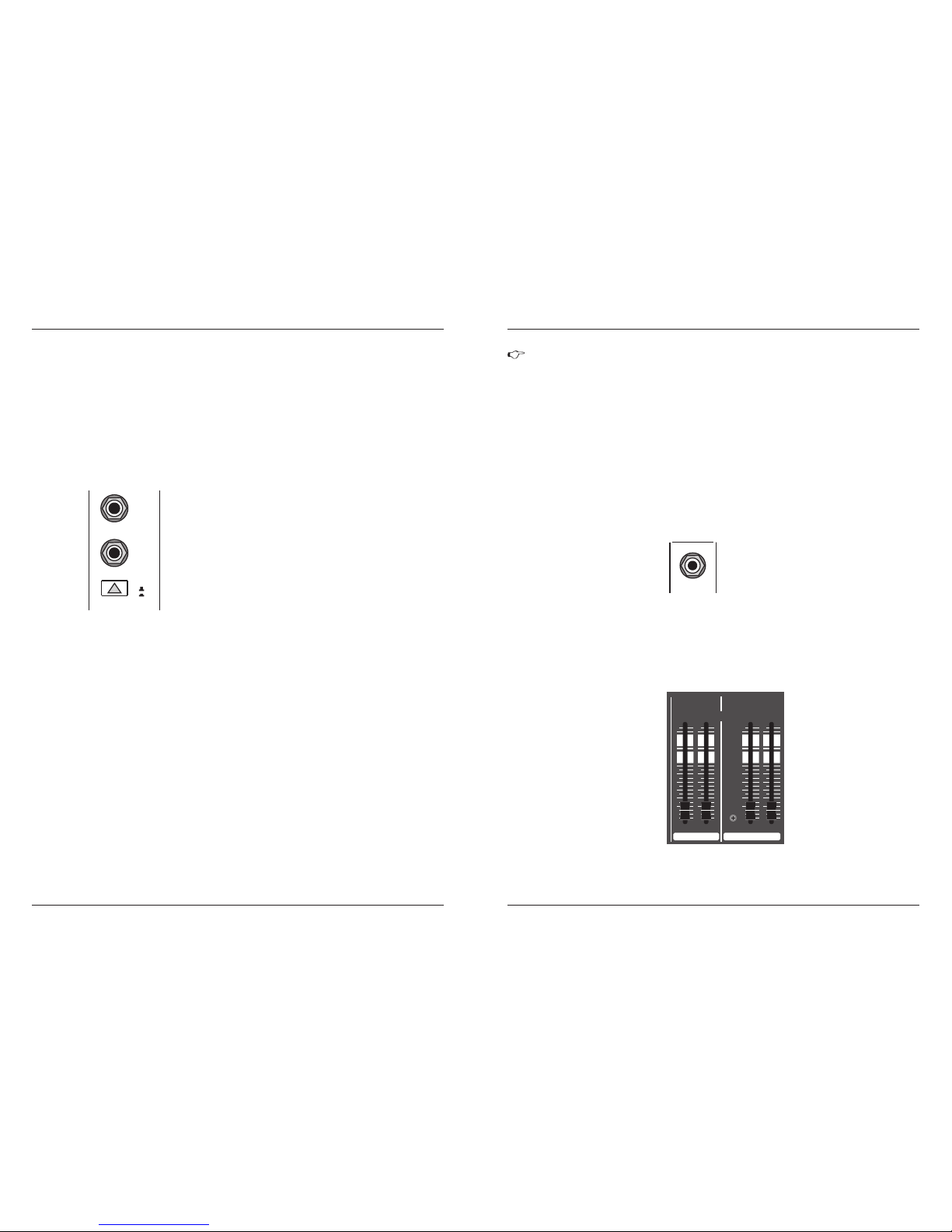
2.2 .1 Chan nel inp uts
LIN E IN 7/8
+4
-10
MONO
L
R
LEVE L
BAL
OR
UNBA L
Fig . 2.5: St ereo ch annel
inp uts and L EVEL sw itc h
Each stereo channel has two balanced line level input on
1/4" connectors for left and right channels. If only the connector
marked “L” is used, the c hannel operates in mono. Stereo
channels are designed to handle typical line level signals.
Both input can also be used with unbalanced jacks.
LEVEL
For level matching, the stereo inputs feature a LEVEL switch
which selects between +4 dBu and -10 dBV. At -10dBV (homerecording level), the input is more sensit ive than at +4 dBu
(studio level).
In principle, the aux sends of the stereo channels function in just the same way as those of the mono
channels. As aux send paths are always mono, the signal on a stereo channel is first summed to mono
before it reaches it reaches the aux bus.
2.2.3 Aux sends stereo channels
The equa lizer of t he stereo channel i s, of cour se, stereo. The filter chara cteristi cs and cro ssover
frequencies are the same as those of the mo no cha nnels . A stereo equal izer i s alwa ys pre ferab le
to mono equa lizers if frequency correcti on of a stereo s ignal is needed. There is often a discrepancy
between the settings of the left and the right channels when using separate equalizers.
2.2.2 Equalizer stereo channels
2.2.4 routing switch, solo and channel fader
The function of the BAL(ANCE) control corresponds to the PAN control in the mono channels.
The balance control determines the relative proportion between the left and right input signals before
both signals are routed to the main stereo mix bus.
The MUTE/ALT 3-4 switch, t he MUTE-LED, the CLP-LED, the SOLO switch and the channel fade r
function in th e same way as the m ono channels.
BAL
PMX Se r i e s M ixer
11
Also a rule, solo signals are monitored via the control room output and headphones connector and are
displayed by the level meters. If a also switch is pressed, the signals from the tape input, Alt 3-4 and main
mix are blocked from the control room outputs, the headphone connector and the level meter.
The PAN control in the channel strip offers a constant power characteristic. This means that
the signal is always at a constant level, irrespective of its position in the stereo panorama.
If the PAN control is moved fully left or right from center, the level increases by 4 dB in that
channel. This signal is not louder. For this reason, with the solo function activated (Solo In
Place), audio signals from the channels with PAN controls that have not be moved fully to
the left or right are displayed at a lower volume that in the PFL function.
MAI N SOLO
The MAIN SOLO LED lights up as soon as a channel or aux send solo switch is pressed. The MODE
switch also has to be set at “solo”.
The PFL LED indicates that the peak metre is set to PFL mode.
PFL
PHO NES
You can connect headphon e to this TRS connector. The signal on the PHONES connection is
sourced from the control room output.
1/4"
PHON ES
Fig . 2.12: P HONES c onnec tor
2.3.7 Alt 3- 4 an d main mi x fa der
Fig . 2.13: A lt 3 -4 and ma in m ix fade r
ALT 3-4 MAIN MI X
10
0
10
15
20
25
30
40
60
8
10
0
10
15
20
25
30
40
60
8
10
0
10
15
20
25
30
40
60
8
10
0
10
15
20
25
30
40
60
8
3 4 L R
Use the high-precision quality faders to control the output level of the Alt 3-4 subgroup and main mix.
Page 10
PMX Se r i e s M ixer
7
2.3 Connector panel and main section
Whereas it was useful to trace the signal flow from top to bottom it order to gain an understanding of
the channel strips, we now look at the mixing console from left to right. The signals are, so to speaker,
colle cted fr om the same po int on e ach of t he channel st rips an d then r outed to the m ain sec tion al l
together.
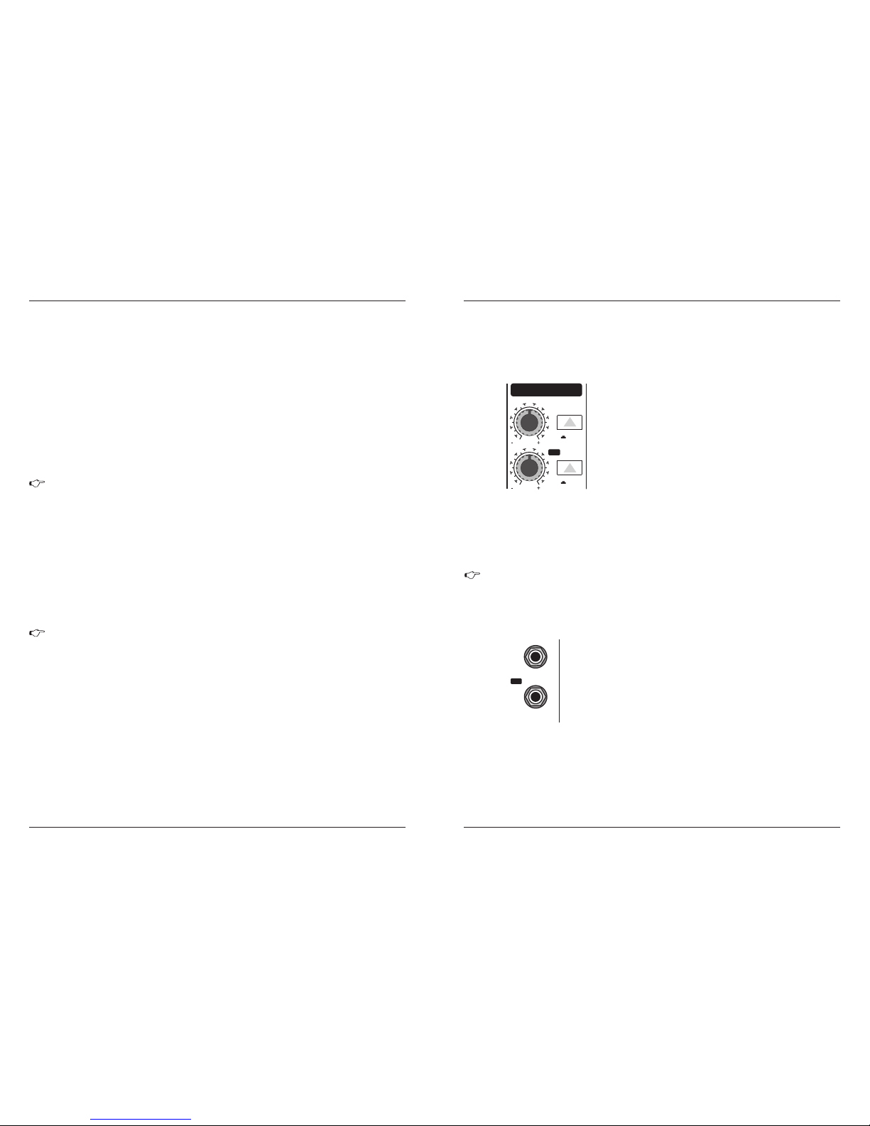
A channel signal is routed to aux send bus 1 if the Aux 1
control is turned up on the corresponding channel.
The AUX SEND control MO N acts as mas ter con trol
for aux send 1 and de term ines the level of the s ummed
sign al.
AUX S END 1 (MO N)
Simi larl y, the FX cont rol (AU X SEND 2) de term ines
the le vel for au x send 2.
AUX S END 2 (FX )
2.3 .1 Aux se nds 1 a nd 2
Fig . 2.6: AU X SEN D contr ols
of th e main se ction
0
15
8
0
15
8
1
2
FX
AUX SEN DS
SOLO
SOLO
You can use the SOLO switch to separately monitor the aux sends via the CONTROL ROOM/PHONES
outputs and check these with the level metres.
SOL O
1
2
FX
AUX SE NDS
If you want to monitor the signal the of just one AUX bus, none of the other SOLO SWITCHES
should be pressed and the MODE switch must be in the SOLO position (not pressed down).
2.3 .2 Aux se nd co nne ctors 1 a nd 2
Fig . 2.7: Au x sen d conne cto rs
AUX S END 1
AUX S END 2
If yo u use a ux sen d 1 pre -fader, y ou wou ld usu ally
conn ect th e AUX SEN D 1co nnect or to m onito rs via a
power amp (or an active monitor system). If you use aux
send 1 post-fader, proceed as described under aux send 2.
The AUX SEND 2 connector outputs the signal you picked up from the individual channels using the
FX control. You can connect this to the input of an effects mix is created, the processed signal can then
be routed from the effects device output back into the STEREO AUX RETURN connectors.
PMX Se r i e s M ixer
10
The MAIN MIX switch sends the main mix signal to the above-mentioned outputs and to the level metre.
MAIN MIX
Use this control to set control room output level and headphone volume respectively.
PHONES/CTRL (ROOM)
When the 2-TRACK TO MAIN switch is depressed, the 2-track input is routed to the main thus serves
as an additional input for tape machines. You can also connect MIDI further processing. At the same time,
this switch disables the main mix to tape output link.
2-TRACK TO MAIN
POWER
The blue POWER LED indicates that the device is switched on.
LEVEL METER
The high-procision level meter accurately displays the appropriate signal level.
+48V
The red “+48V” LED lights when the phantom power supply is switch on. The phantom power supply
is necessary for condenser microphones and is activated using the switch on the rear of the device.
Please do not connect microphones to the mixer (or the stagebox/wellbox) while the phantom
power supply is switched on. Connect microphones before you switch on the power supply.
In addition, the monitor/PA loudspeakers, should be muted before you activate the phantom
power supply. After switching on, wait approx. One minute to allow for system stabilization.
When recording to a digital device, the recorder ’ s peak metre should mot exceed 0 dB. This is because,
unlike analog recordings, slightly excessive levels can create unpleasant digital distortion.
LEVEL SETTING
When recording to an analog device, the VU meters of the recording machine should reach approx.
+3 dB with low-frequency signals (e.g. Kick drum). Due to their inertia VU meters tend to display too low
a signals level at frequencies above 1 kHz. This is why ,for example, a Hi-Hat should only be driven as
far as -10dB. Snare drums should be driven to approx. 0 dB.
The peak metres o f your XE NYX displ ay the le vel virtu ally ind ependent of frequ ency. A
record ing level of 0dB is recommen ded for a ll signal types.
PFL
To activate the PFL function, depress the MODE switch. The PFL function should, as a rule, be used
for gain setting purposes. The signal is sourced pre-fader and assigned to the mono PFL bus. In the “PFL”
setting, only the left side of the peak meter operates. Drive the individual channels to the 0 dB mark of
the VU meter.
SOLO
When the MODE switch is not de pressed, the ste reo solo bus is ac tivate. Solo is short for “Solo I n
Place”. This is the customary method for listening to an individual signal or to a group of signals. As soon
as a so lo swi tch is p resse d, all c hannels in th e control roo m (and headph ones) that ha ve not b een
selected are muted thereby re taining stereo panning. The solo b us can carry the output signals o f the
channel pan controls, the aux sends and the stereo line inputs. The solo bus is, as a rule, switched postfader.
MODE
The MODE switch determines whether the channels’ SOLO switch operates as PFL (Pre Fader Listen)
or as solo (Solo In Place).
Page 11
PMX Se r i e s M ixer
8
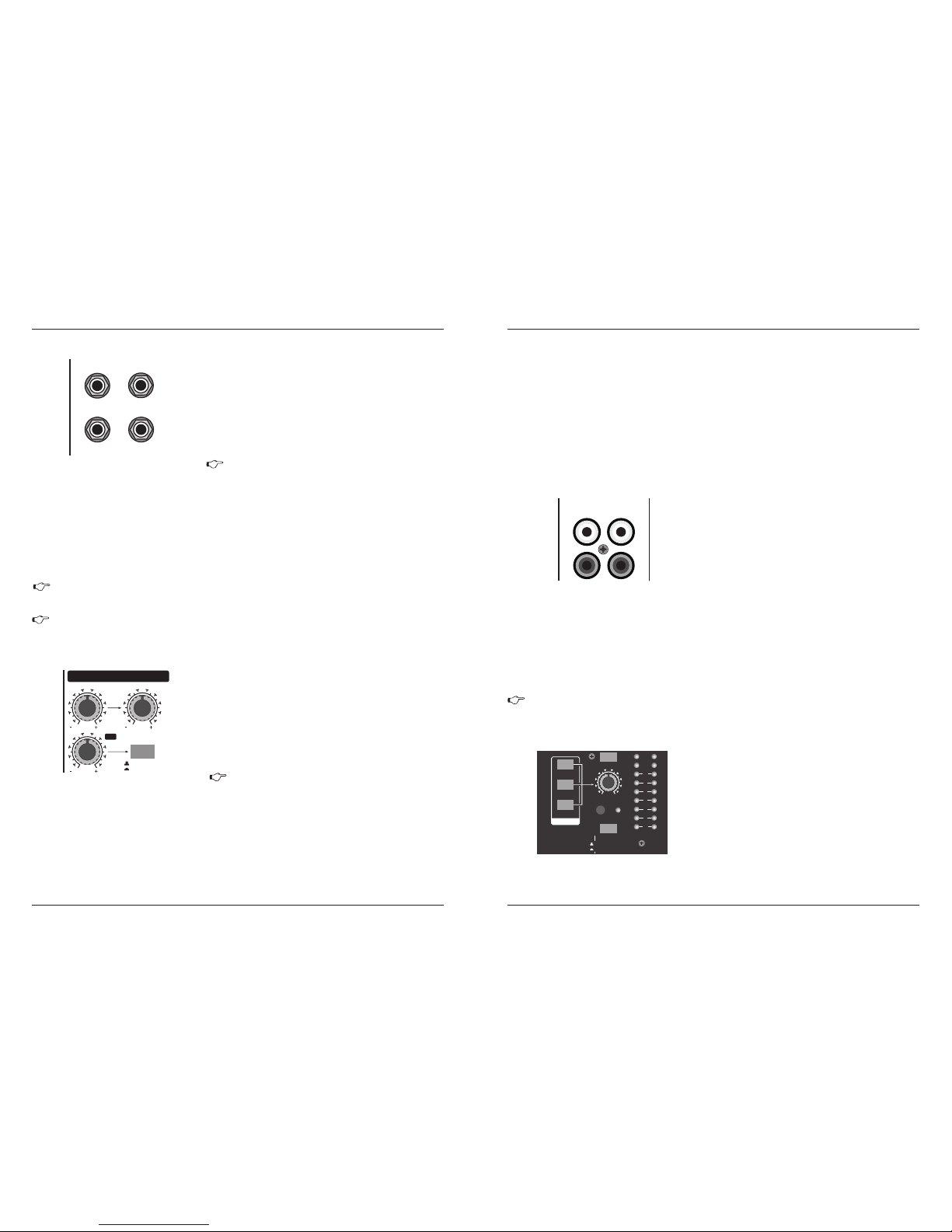
STE REO AUX RE TURN 1
The STEREO AUX RETURN 1 connectors generally serve
as the return path for the effects mix generated using the postfader aux send. This is where you connect the output signal
of the external effects device. If only the connector is used,
the AUX RETURN automatically operates in mono.
If you wis h to use the i nternal effects proce ssor, no connectors should be plugged i nto
STEREO AUX RE TURN 2.
In this instan ce, the FX control of the channel be ing used as an effe cts return shoul d be
turned fully c ounterclockwise, otherwise feed back problems could occur!
STE REO AUX R ETU RN 2
You can also use these connectors as additional
line inputs.
The STEREO AUX RETURN 2 connectors serve as the return path for the effects mix generated using
the FX control. If these connectors already function as additional inputs, you can route the effects signal
back into the console via a different channel, with the added benefit that the channel EQ can be used to
adjust the frequency of the effects signal.
2.3 .3 Ster eo aux re turn co nnect ors
Fig . 2.8: St ereo au x retur n conne ctors
LEF T/MONO R IGHT
1
2
RET URNSSTE REO AUX
STE REO AUX R ETU RN 1
2.3 .4 Ster eo aux re turn
Fig . 2.9: St ereo au x retur n contr ols
0
8
0
8
1
2
0
8
1
STERE O AUX RET URNS
MAIN M IX
ALT 3-4
TO AUX
SEND 1
88
8
FX
ST ER EO AU X RE TUR N 1 is a ste reo co ntr ol w hic h
determines is used as effects return, you can add the effects
signal to any ”dry” channel signal .
In this instance, the effects device should be set
at 100% effect.
Mon itor mi x with ef fect
STE REO AUX R ETU RN MON
The STEREO AUX RETURN MON control has a special function: it can be used to add an effect to a
monitor mix.
In this instance, the effect device should be set up as follows: AUX SEND 2 is connected to the L/Mono
input of your effects device, while its outputs are connected to STEREO AUX RETURN 1. Connect the
amplifier of your monitor system to AUX SEND 1. The AUX SEND 1 master control determines the volume
of the monitor mix.
PMX Se r i e s M ixer
9
You can now use the STEREO AUX RETUR N MON contro l to adjust t he level of t he effects si gnal
routed to the monitor mix.
The STEREO AUX RETURN 2 control determines the level of signal s fed into the AUX RETURN 2
connectors which are routed to the main mix.
STE REO AUX R ETU RN 2 (FX)
MAI N MIX/A LT 3-4
The MAIN MIX/ALT 3-4 switch routes the signal connected to STEREO AUX RETURN 2 to either main
mix (not pressed) or submix (Alt 3-4, pressed).
2-T RACK OU TPUT
These connectors are wired in parallel with MAIN OUT and carry the main mix signal (unbalanced).
Connect the 2-TRACK OUTPU T to the inputs o f your recordi ng device. The f inal output le vel can be
adjusted via the high-precision MAIN MIX fader.
If you connect a compressor or a noise gate after the 2-track output, the faders will probably
not be able to create a satisfactory fade-out effect.
2-T RACK IN PUT
The 2-TRACK INPUT RCA connectors are provided for
connecting a 2 track machine (e.g. DAT recorder). They
can also be used as ster eo line input . Alternatively, the
output signal of a second MX Series Mixing can also be
connected. If you connect a hi fi amplifier with a source
selection switc h to the INPUT, you can easily 2-TRACK
switch between additional sources (e.g. Cassette recorder,
CD player, etc.).
2.3 .5 Tape in put /tape o utput
Fig . 2.10: 2 -trac k conne ctors
INPU TLOUTP UT
2TK TO M AIN MIX
L
RR
Similarly, the ALT 3-4 switch routes the signal from the
Alt 3-4 bus to the same path for monitoring purposes.
ALT 3- 4
The TRACK switch routed, the signal from the TRACK
IN connectors to the level metre, the CONTROL ROOM
OUT outputs and the PHONES connector----this is a simple
way to che ck recorde d signals v ia monitor speakers or
headphones.
2-T RACK
2.3.6 Level met er a nd m on it oring
Fig . 2.11: Co ntr ol room /phon es sect ion,
lev el mete r
- +15
8
3 4
MODE
SOLO (NORM AL)
PFL (LEVE L SET)
L R
MAIN SOL O PFL
MAIN MIX
ALT 3-4
2-TRACK
PHONES /CTRL R
SOURC E
2TK TO MAI N MIX
POWER +48 V
CLIP
10
5
2
0
2
5
20
 Loading...